an engineering design strategy for reconfigurable products that … · 2013-12-27 · p vector of...
TRANSCRIPT

Proceedings of the ASME 2010 International Design Engineering Technical Conferences &Computers and Information in Engineering Conference
IDETC/CIE 2010August 15-18, 2010, Montreal, Quebec, Canada
DETC2010-28739
AN ENGINEERING DESIGN STRATEGY FOR RECONFIGURABLE PRODUCTSTHAT SUPPORT POVERTY ALLEVIATION
Patrick K. LewisPhd Student
Dept. of Mechanical EngineeringBrigham Young University
Provo, Utah 84602Email: [email protected]
Christopher A. Mattson∗Assistant Professor
Dept. of Mechanical EngineeringBrigham Young University
Provo, Utah 84602Email: [email protected]
Vance R. MurrayResearch Assistant
Dept. of Mechanical EngineeringBrigham Young University
Provo, Utah 84602Email: [email protected]
ABSTRACTReconfigurable products can adapt to new and changing
customer needs. One potential, high-impact, area for productreconfiguration is in the design of income-generating productsfor poverty alleviation. Non-reconfigurable income-generatingproducts such as manual irrigation pumps have helped millionsof people sustainably escape poverty. However, millions of otherimpoverished people are unwilling to invest in these relativelycostly products because of the high perceived and actual financialrisk involved. As a result, these individuals do not benefit fromsuch technologies. Alternatively, when income-generating prod-ucts are designed to be reconfigurable, the window of affordabil-ity can be expanded to attract more individuals, while simulta-neously making the product adaptable to the changing customerneeds that accompany an increased income. The method pro-vided in this paper significantly reduces the risks associated withpurchasing income-generating products while simultaneously al-lowing the initial purchase to serve as a foundation for future in-creases in income. The method presented builds on principles ofmultiobjective optimization and Pareto optimality, by allowingthe product to move from one location on the Pareto frontier toanother through the addition of modules and reconfiguration. El-ements of product family design are applied as each instantiationof the reconfigurable product is considered in the overall designoptimization of the product. The design of a modular irrigationpump for developing nations demonstrates the methodology.
∗Address all correspondence to this author.
Nomenclature
δ Matrix dictating the desired progression that eachmodule provides
D Set containing all design variable valuesDm Set containing all variable values of xm and xp
D(i) Design (i) of set Dg Vector of inequality constraintsh Vector of equality constraintsµ Vector of design objectivesnd Number of designs comprising the adaptive
design setng Number of inequality constraintsnh Number of equality constraintsnµ Number of design objectivesnµ Number of additional objective constraints
needed to define anticipated regions of interestnm Number of modules desirednx Number of design variablesnxa Number of adjustable design variablesnxm Number of module design variablesnxp Number of platform design variablesP Objective space performance of the base and
target designs used to develop modulesP(i) Objective space performance of a design when
used with the i-th module∆P(i) Change in objective space performance from the
base design to P(i)
1 Copyright © 2010 by ASME
Proceedings of the ASME 2010 International Design Engineering Technical Conferences & Computers and Information in Engineering Conference
IDETC/CIE 2010 August 15-18, 2010, Montreal, Quebec, Canada
DETC2010-28739
p Vector of design parametersx Vector of design variablesxa Vector of non-platform design variables that are
either scaled or discretely adjustedxm Vector of non-platform design variables that
characterize the design of modulesxp Vector of platform design variables
1 IntroductionThere is increasing evidence that one of the most sustain-
able ways to help those living in extreme poverty (20.5% of theworld’s population who live on less than ∼$1 a day) is througha market-based approach – where all in the supply chain benefitfinancially, including the poor [14, 18, 24, 52]. Among the mostpromising methods of producing profit for all in the supply chainis the development of products that increase the earning powerof those that are living in extreme poverty [1, 14, 40]. Productssuch as treadle pumps, water drip irrigation kits, and coconut oilpresses have generated millions of dollars in profit for povertystricken countries and helped over 12 million people sustainablyescape poverty [1, 14, 40]. However, millions of other impover-ished people throughout the world are unwilling to invest in rel-atively costly income-generating products (∼$100 – or 3 monthsof income) because of the high perceived and actual financial riskinvolved [14, 20, 52]. Additionally, a majority of the populationcannot afford the investment under the traditional approaches,and therefore remain unaided by these poverty alleviating tech-nologies.
Reconfigurable products, those that can adapt to new andchanging customer needs, have the potential to significantly alterthe impact that income-generating products can have on povertyalleviation efforts. An unequivocal need, as described by thoseleading the market-driven approach to sustainable poverty re-lief, is a method for bringing income-generating products tomore people by reducing the risk associated with the invest-ments [14, 23, 43]. The risks, irrevocably connected to productcost, would be effectively mitigated with engineering methodsthat embrace extreme affordability. When income-generatingproducts are designed to be reconfigurable, the window of af-fordability can be expanded to attract more individuals, while si-multaneously making the product adaptable to the changing cus-tomer needs that accompany an increased income over time.
Under the engineering design strategy presented in this pa-per, numerical optimization is used to identify a set of desirabledesigns that meet the varying needs of those living in extremepoverty. Moreover, the set of designs are selected based on theability of the design to be realized though the addition of mod-ules or reconfiguration. The goal of the strategy is to allow fora changing tradeoff preference between income generation po-
tential and investment cost. As shown in this paper, this strat-egy significantly reduces the risks associated with purchasingincome-generating products while simultaneously allowing theinitial purchase to serve as a foundation for product and incomeexpandability. Ultimately, the presented method allows income-generating products to be made more affordable by their strategicmodularity and reconfigurable nature, which makes them pro-gressively expandable, thus facilitating incremental investmentand extreme affordability.
The remainder of this paper is presented as follows: A re-view of literature forming an enabling foundation for the devel-opment of the proposed method is included in Section 2. InSection 3, the theoretical development of the proposed designmethod is presented. In Section 4 the design of a manually pow-ered irrigation pump is used to demonstrate the method. Con-cluding remarks are provided in Section 5.
2 Literature SurveyThis section provides a brief review of previous pertinent
research, and establishes a foundation for the strategy presentedin the following section for designing reconfigurable productsthat support poverty alleviation.
2.1 Engineering-based Poverty AlleviationThe literature characterizes poverty alleviation as providingthose trapped in poverty with the ability to permanently es-cape [14, 17, 49, 51]. To provide this, sustainable developmentis required. Sustainability, however, is a complex attribute thatinvolves economic, social, environmental, technological, andpolitical factors [4, 40]. A close examination of the past 20years of literature shows that evolutions in poverty alleviationstrategies can be divided into two major phases: (i) appropri-ate technology [8, 14, 44] and (ii) market-based development[14, 18, 20, 23, 26, 42, 52].
The foundations of poverty alleviation through sustainabledevelopment were laid in the 1920’s when Mahatma Gandhiencouraged the development of rural technologies to help In-dia’s villages to become more self-reliant [32]. As time pro-gressed, the rich of the world continued to become richer andthe poor remained impoverished [19]. In the 1970’s the engi-neering design community began to formally address the grow-ing problem of poverty [8, 43], and with this the appropriatetechnology movement became the strategy implemented for thenext 15 years [14, 40]. Appropriate technology is described inthe literature as the design of technologies that carefully con-sider the environmental, ethical, cultural, social, and economicaspects of the community it is intended for [8]. Character-istics of this movement include: adherence to a communityownership/maintenance philosophy, implementation of simple
2 Copyright © 2010 by ASME

time saving technologies, development of labor-intensive solu-tions, low capital cost solutions, use of locally available nat-ural resources where possible, and low maintenance cost solu-tions [8, 14, 44].
In the fifteen years that the appropriate technology move-ment was the foremost approach to poverty alleviation, somepractitioners noticed that the movement failed to provide sustain-able results [10,14,38,40,41]. Identifying the weaknesses of themovement (too much emphasis placed on time and labor savingdevices; developed technologies did not create individual oppor-tunities; abandonment of implemented technologies after a shortperiod of time; etc.) [14, 40], adjustments were made, and themarket-based development phase in poverty alleviation strategiesbegan [14, 40, 41, 45]. Market-based development addresses theissue of poverty alleviation by “not only designing technologies‘appropriate’ to the poor, but also designing technologies thatpeople in poor places [can] themselves appropriate and use toadvance their own ends" [14]. To create products that can gen-erate more income for the poor requires an understanding of thedynamics of the local culture and product markets [23]. Charac-teristics of this approach include: focusing on the developmentof technologies that create business opportunities for individuals,selling products to promote self-sufficiency [20], and establish-ing permanent, profitable, and locally marketed/advertised sup-ply chains [11, 14].
Since the establishment of the market-based approach, pub-lished literature has indicated that poverty alleviation approachesthat create individual opportunities [14, 24, 42], encourage self-esteem [14, 23, 42], offer choices [6, 14, 42, 52], and fosterself-sufficiency by increasing earning power [14, 18, 24, 52] forthe poor have had the most measurable, and sustainable affecton poverty. A fundamental thread in these sustainable meth-ods is their market-based nature, where everyone in the sup-ply chain benefits from the alleviation efforts [14, 18, 24, 52].Methods that do not do this have simply not been self sustain-ing [14,23,52]. Recent reports by companies that design income-generating products (such as irrigation pumps and drip irrigationsystems for small farm owners) have shown that these productshave measurably and sustainably helped over 12 million peopleescape poverty [1,14,40]. These products, priced at roughly $100(roughly 3 months income) [14], were introduced under a marketcentric approach where all in the supply chain benefit.
2.2 Multiobjective Optimization as a Foundation forReconfiguration
The need for extreme product-affordability changes over timefor those living in poverty when income-generating products areused. As more income is generated, other products become moreand more affordable. The ability to balance the competing na-ture of present customer needs for affordability against future
needs for higher productivity is fundamental to the presentedmethod. Multiobjective optimization is used as a foundation forfinding the needed balance [21, 25, 39, 47, 53]. The set of de-sign options that best balance the design tradeoffs belong to thePareto frontier, which is the set of all non-dominated optimalsolutions. We seek Pareto optimal designs because they rep-resent feasible designs for which the objectives have been im-proved as much as possible without sacrificing another designobjective’s performance by improving another objectives feasi-ble performance [3, 9]. Under the developments of this paper,we ultimately seek conditions for which each instantiation of areconfigurable product is close to the Pareto frontier.
The following formulation yields the Pareto frontier for anygeneric design case; min
x
{µ1(x, p), µ2(x, p), ..., µnµ
(x, p)}
.
Subject to g(x, p) ≤ 0, h(x, p) = 0, and xl ≤ x ≤ xu. Where µidenotes the i-th generic design objective; g and h represent in-equality and equality constraints, x is a vector of design variables;and p is a vector of design parameters.
For multiobjective optimization approaches, the decision ofwhich Pareto optimal solution to select comes through the inclu-sion of objective function parameters, and sometimes constraintsthat capture customer needs or preferences for a single instancein time [29, 30]. The method presented in this paper builds onprinciples of Pareto optimality, by allowing the product to movefrom one location on the Pareto frontier to another through theaddition of modules and through reconfiguration. This move-ment is intended to occur over time as customer preference andneeds change.
2.3 Product Modularity and ReconfigurationAs described in detail in the next section, a desirable product (oneresiding near the Pareto frontier) may be adapted to become adifferent desirable product (another one residing near the Paretofrontier) through the addition of modules and reconfiguration.This calls for the strategic design of platforms and modules thatmake products progressively expandable [15, 27, 28]. Previouswork in the areas of product family, modularproduct, and flexiblesystem design serve as a starting point, and as a source for designprinciples. [12, 15, 16, 28, 46, 50, 55–57]
A module-based product family is a group of related prod-ucts derived from independent functional or geometric units[2, 37, 48] that differ through the addition or subtraction of mod-ules [37, 48, 56]. In the literature three basic types of modularityare identified: (i) Slot-modular architecture, (ii) Bus-modular ar-chitecture, and (iii) Sectional-modular architecture [35, 36, 48].A slot-modular architecture provides each module with a uniqueinterface in order to eliminate improper assembly [35, 36, 48].Bus-modular architecture implements interfacing that is the samefor all modules, thus making the platform design behave as acommon connection platform for all modules [48]. Sectional-
3 Copyright © 2010 by ASME

modular architecture is similar to bus-modular in that all mod-ules contain the same interface, but in this architecture no singleelement is identified as the platform to which all modules at-tach [35, 48]. In the present paper we use these definitions ofmodular architectures to specify the approach needed to developmodule designs according the a desired architecture type.
Although similar to module-based products, flexible prod-ucts focus on implementing design components of adaptability(design variable values change due to predictable functional needchanges) and design robustness (setting of fixed design variablevalues to account for unpredictable environmental and other op-erational condition changes) [13, 33, 34]. Otherwise stated, themajor difference between the two strategies is that flexible prod-ucts ajust an existing design, while module-based products add orsubtract modules to satisfy various needs [12, 13, 16, 33, 34, 46].In the present paper we use the concepts of adjustablility (re-congigurability) in flexible product design to further enhance theability of a modular product to adjust to new and changing needsover time.
The coupling of product modularity design principles andmultiobjective optimization also plays an important role in thedevelopments presented in this paper. Recent developments inthe literature show that a desirable product family can be iden-tified from among the designs comprising the Pareto frontier[55, 57]. These previous developments evaluate and select prod-uct family members from among the set of Pareto designs by con-sidering the design’s unique performance and common featurescompared to other designs in the product family (a critical partof product family design). In addition, one method of identifyingmodule and platform variables is accomplished through the useof Pareto-filtering methods that explore the effects of each vari-able on the objective space performance [55, 57]. Building onthese approaches as a foundation, in the proposed method a se-lection criteria based on known changes in customer needs overtime is added to the evaluation – to ensure that a progression fromone design on the Pareto front to another can be done through theaddition of a module.
3 A New Strategy for Designing Reconfigurable Prod-uctsIn this section, we present an optimization-based design
strategy that can be used to identify a set of reconfigurable prod-uct instantiations realizable through the addition of modules.Moreover, the strategy also includes a process for designing therequired modules. An illustration of the strategy is provided asa flow diagram in Fig. 1. The purpose of this section is to pro-vide details and mathematical formulations for the steps of thisprocess. Each step is now discussed.
Figure 1. Flow chart describing the five-step multiobjective optimization de-sign method developed in this section.
3.1 Characterize the Multiobjective Design SpaceThe method first seeks to characterize the design space by identi-fying feasible and optimal values for the design objectives. Theseare identified by formulating and executing a Multiobjective Op-timization Problem (MOP) of the form described in Sec 2.2.2.The result is a set of optimal solutions – those belonging to thePareto frontier. This step is a fundamental part of the process asit is the step that allows the designer to understand the range ofoptimal performance possibilities. From a graphical perspective,Step A identifies a Pareto frontier, shown as a bold line in Fig. 2for a problem where both objectives are minimized.
3.2 Define Anticipated Regions of InterestThis step of the process allows the designer to choose regionsaround portions of the Pareto frontier within which product re-configurations will be sought. In that way, each region is as-sumed to contain candidates for handling a different set of cus-tomer needs that are anticipated to occur over time. Furthermore,
4 Copyright © 2010 by ASME

it is within these regions that designs, well-suited for modularity,are sought.
µ1
µ2
µ1u(3)µ1l
(1) µ1u(1) µ1l
(2) µ1u(2) µ1l
(3)
InterestRegions
µ2u(3)
µ2l(3)
µ2l(2)
µ2l(1)
µ2u(2)
µ2u(1)
ParetoFrontier
FeasibleDesignSpace
Figure 2. Representation of the construction of Anticipated Regions of Interestfor known changes in customer needs for three intervals. For the case shown, theanticipated regions of interest provide inequality constraints for both µ1 and µ2.
The fundamental concept of this step is illustrated in Fig-ure 2. For each anticipated region of interest, a new MOP, witha reduced design space based on the region of interest (shaded),is defined by additional objective constraints. For example, forthe region of interest presented in Figure 2, the j-th design ob-jective (µ j) is constrained within the i-th region of interest byµ
(i)j,l ≤ µ
(i)j ≤ µ
(i)j,u, where µ
(i)j,l and µ
(i)j,u are prescribed. The result
is a bounded MOP for searching the design space only within theanticipated region of interest.
3.3 Select Platform VariablesThe third step of the process considers the Pareto designs withinthe regions of interest to identify the variables that are best suitedas platform variables (xp). This may be accomplished through theuse of Pareto-filtering methods as described in Section 2.2.3 orany other suitable method. As a tradeoff to modularity, a shiftin the Pareto frontier is likely to occur. Thus, once the platformvariables are selected, steps A and B may be repeated, as shownin Figure 1, to insure that the resulting shift in the Pareto frontieris acceptable to the designer. In the context of poverty allevi-ation, this step selects the best possible platform variables thatwill allow for extreme affordability and subsequent addition ofmodules that satisfy desired objectives, particularly those relatedto affordability.
3.4 Select the Optimal Design Within Each Region ofInterest
The purpose of this step is to develop and execute an optimizationproblem for selecting the best design in each anticipated regionof interest and identify the accompanying design variable values.The resulting optimal design set (D) containing all variable val-ues is obtained through the following MOP formulation:
Problem 1a: MOP Formulation for Optimal Adaptive ProductIdentification
D := {(xp,1,xp,2, ...,xp,nxp,x(i)
a,1,x(i)a,2, ...,x
(i)a,nxa
) |∀i ∈ {1,2, ...,nd}} (1)
xp,x(i)a defined by:
minx(i)
a xp
1nd
nd
∑n=0
J(i) (2)
where:
minx(i)
a , xp
J(i) = w(i)1 ·µ1(x
(i)a ,xp, p(i))m +w(i)
2 ·µ2(x(i)a ,xp, p(i))m
+, ...,+w(i)nµ·µnµ
(x(i)a ,xp, p(i))m (nµ ≥ 2) (3)
subject to:
g(i)q (x(i)
a ,xp, p(i))≤ 0 ∀q ∈ {1, ...,n(i)g } (4)
h(i)k (x(i)
a ,xp, p(i)) = 0 ∀k ∈ {1, ...,n(i)h } (5)
xa, j,l ≤ x(i)a, j ≤ xa, j,u ∀ j ∈ {1, ...,nxa} (6)
xp,r,l ≤ xp,r ≤ xp,r,u ∀r ∈ {1, ...,nxp} (7)
µ(i)y,l ≤ µ
(i)y ≤ µ
(i)y,u ∀y ∈ {1, ...,n(i)
µ} (8)
where the adjustable variables (xa) represent all non-platformdesign variables (variables that are either scaled or dis-cretely adjusted); m is a compromise programming power [5];w(i)
1 ,w(i)2 , ...,w(i)
nµare weights associated with the local preference
within each region of interest; the set D now represents the setof all design variable values of xa and xp obtained through theevaluation of the MOP; and the superscript (i) on p, g, and h
5 Copyright © 2010 by ASME
indicate the possibility that parameters and constraints are differ-ent (non-constant) for each design in the set D. It is important tonote that Problem 1a will result in a single solution within eachregion of interest which are selected by finding the set of nd de-signs with the best average aggregate objective function values(see Equation refP1:obj1). It is also important to note that be-cause the platform variables are already identified and used inthis step, the resulting designs already share commonality whichis the basis for reconfiguration through modularity.
Although not the focus of this paper, it is recognized thatthe weights indicated in Equation refP1:obj2 will need to be de-termined for actual design scenarios. For the method presentedherein it is assumed that this information is known, but potentialmethods for determining these weights could include the use ofmarket surveys, focus groups, or other suitable methods.
3.5 Develop Modules That Move From One Region ofInterest to Another
By this step in the process, the set D now contains all variablevalues that can be used to develop the module designs. Develop-ing these designs is now a matter of constrained module design –modules are designed in a manner that constrains them to providea specified progression in product performance when added to aspecific embodiment of the product while only using the variablevalues from set D. To complete this final step of the method andobtain the module designs requires the following: (i) Select amodular architecture type, (ii) Identify the platform design andmodule interfaces, (iii) Determine the desired number of mod-ules and modular progression, and (iv) Identify and calculate thevalues of module design variables. Each of these four parts isbriefly discussed.
Select a modular architecture type: Of the three typesof modularity identified in the literature (see Section 2.2.3),Slot-modular architecture and Bus-modular architecture are bestsuited for implementation in the present method due to the useof platform designs. The decision of which architecture type tobe used depends on the desired functionality of the product andmodules as a whole.
Identify the product platform design and module inter-faces: Prior to the identification of modules, one of the designs inset D must be identified as the product platform design. In orderto facilitate adaptability, the platform design is generally iden-tified as the design contained in D with the most commonality.In addition, the module interfaces must be specified according tothe modular architecture type selected previously and the infor-mation provided in δ , and any other related interfacing designactivities must be performed.
Determine the desired number of modules and the modu-lar progression: With a knowledge of the modular architecturetype that is desired, it is now possible to determine the number of
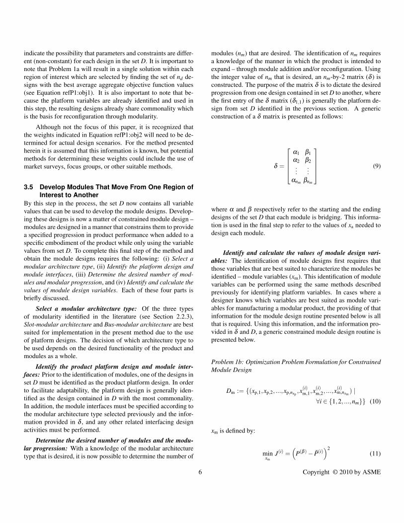
modules (nm) that are desired. The identification of nm requiresa knowledge of the manner in which the product is intended toexpand – through module addition and/or reconfiguration. Usingthe integer value of nm that is desired, an nm-by-2 matrix (δ ) isconstructed. The purpose of the matrix δ is to dictate the desiredprogression from one design contained in set D to another, wherethe first entry of the δ matrix (δ1,1) is generally the platform de-sign from set D identified in the previous section. A genericconstruction of a δ matrix is presented as follows:
δ =
α1 β1α2 β2...
...αnm βnm
(9)
where α and β respectively refer to the starting and the endingdesigns of the set D that each module is bridging. This informa-tion is used in the final step to refer to the values of xa needed todesign each module.
Identify and calculate the values of module design vari-ables: The identification of module designs first requires thatthose variables that are best suited to characterize the modules beidentified – module variables (xm). This identification of modulevariables can be performed using the same methods describedpreviously for identifying platform variables. In cases where adesigner knows which variables are best suited as module vari-ables for manufacturing a modular product, the providing of thatinformation for the module design routine presented below is allthat is required. Using this information, and the information pro-vided in δ and D, a generic constrained module design routine ispresented below.
Problem 1b: Optimization Problem Formulation for ConstrainedModule Design
Dm := {(xp,1,xp,2, ...,xp,nxp,x(i)
m,1,x(i)m,2, ...,x
(i)m,nxm
) |∀i ∈ {1,2, ...,nm}} (10)
xm is defined by:
minxm
J(i) =(
P(β )− P(i))2
(11)
6 Copyright © 2010 by ASME

where:
α = δi,1 (12)
β = δi,2 (13)
P(i) = P(α) +∆P(i) (14)
defined by:
P(α) =(
µ1(x(α)a ,xp, p(α)), µ2(x
(α)a ,xp, p(α))
, ..., µnµ(x(α)
a ,xp, p(α)))
(nµ ≥ 2) (15)
P(β ) =(
µ1(x(β )a ,xp, p(β )), µ2(x
(β )a ,xp, p(β ))
, ..., µnµ(x(β )
a ,xp, p(β )))
(nµ ≥ 2) (16)
∆P(i) =(
∆µ1(x(i)m ,xp, p(i)), ∆µ2(x
(i)m ,xp, p(i))
, ..., ∆µnµ(x(i)
m ,xp, p(i)))
(nµ ≥ 2) (17)
where Dm is the set of values and variables of xp and xm for eachmodule design; P(α) and P(β ) characterize the objective spaceperformance of the base (α) and target (β ) designs; P(i) repre-sents the objective space performance of design α when used inconjunction with the i-th module; ∆P(i) represents the change inobjective space performance from design α to P(i); and xm rep-resents the value(s) and variable(s) that characterize ∆P.
Upon completion of Step E, the set Dm contains the neces-sary variables and values needed to define the module designs.As a result, a product capable of adapting to changes in customerneeds over time through the addition of modules is achieved.In addition, each reconfigured iteration of the product obtainedthrough the addition of modules to the identified platform de-sign is required to provide the optimal performance according tothe objectives provided in Problem 1a (see Section 3.3.4). Aspresented in the next section, this 5-Step method is used to de-sign a reconfigurable, manually powered, irrigation pump for de-veloping nations. The process results in a design that strategi-cally moves along the Pareto frontier that starts at the lowest costpump, and transitions to a large capacity pump by module addi-tion.
4 Example: Manual Irrigation PumpThe example that follows shows the application of the method-ology present in the previous section in the creation of a modu-lar, manually operated irrigation pump. In addition, the exampledemonstrates the ability of the method to provide a modular in-come generating product that allows the purchaser to make a 3stage investment to purchase a product that would otherwise beconsidered unaffordable.
Drive for the development of this modular pump is best illus-trated though the plot provided in Figure 3. This figure providesa comparison of various non-modular irrigation pumps that aresold on the market today based on their sales price, S (horizon-tal axis), and potential water flow rate, Q (vertical axis). FromFigure 3 it is seen that products are available to satisfy a range ofcurrent views of what is considered affordable, but none of theseproducts are capable of expanding as an individual’s view of af-fordability changes due to increases in income potential (i.e. aHip Pump cannot become a Super MoneyMaker). In short, drivefor the development of a modular irrigation pump stems fromthe need to reduce the high perceived and actual financial risksinvolved with purchasing traditional irrigation pumps, [14,20,52]while still providing the needed pump performance that will in-crease the purchasers income. To overcome this disparity, ana-lytical models of the fluid and financial aspects of an irrigationpump are developed (see Equations 29-45 of Problem 2a below)to predict the behavior of a pump design based on a set of modelinputs.
SuperMoneyMaker
MoneyMakerPlus
30 40 50 60 70 80 90 100 1100
0.2
0.4
0.6
0.8
1
1.2
1.4
1.6
1.8
2
Sales Price ($)
Flow
Rat
e(L
/s)
MoneyMakerHip Pump
Figure 3. Graphical comparison of three non-modular water pumps that arecurrently sold on the market. The horizontal axis represents the sales price (S inUS dollars, and the vertical axis represents the potential water flow rate (Q) inliters per second.
Assumptions made in the development of the analytical fi-nancial and fluid models presented in Equations 29-45 of Prob-
7 Copyright © 2010 by ASME

Table 1. Limits describing the three anticipated regions of interest (ARI)within the design space of Q and S. Values for each region are basedon the performance of the MoneyMaker Hip Pump (ARI 1), MoneyMakerPlus (ARI 2), and the Super MoneyMaker (ARI 3) in terms of S and Q[7,14,22,54].
ARI # Smin ($) Smax ($) Qmin (L/s) Qmax (L/s)
1 20 40 0.25 0.80
2 40 70 0.90 1.15
3 90 110 1.35 2.0
lem 2a are as follows: (1) Water flow will always be turbulent.(2) The corresponding friction coefficients for flow in the pumpcylinder ( fc) and pipes ( fp) are approximated by the average fric-tion value for the expected flow speeds and the ratios of the sur-face roughness (ε) to pipe/cylinder diameter (dp and dc respec-tively). (3) The force transmission efficiency of the pump (η) isassumed to be constant and equal to 80%. (4) During leg opera-tion of the pump, the force applied by the pump operator (Fl) isassumed to be constant and equal to 889.6 N. (5) During handoperation of the pump, the force applied by the pump operator(Fh) is assumed to be constant and equal to 70% of Fl (622.72 N).(6) The design variable best suited for manufacturing a reconfig-urable, modular irrigation pump is the piston cylinder diameter(dc).
Using the information provided in Figure 3 and the knowl-edge of the assumptions made in developing the analytical mod-els, the anticipated regions of interest within the design space aredeveloped based upon the values of Q and S for the three prod-ucts shown. The limits describing the three anticipated regions ofinterest (ARI) within the design space of Q and S are provided inTable 1. Values of the limits for each region are based on the per-formance of the MoneyMaker Hip Pump (ARI 1), MoneyMakerPlus (ARI 2), and the Super MoneyMaker (ARI 3) in terms of Sand Q [7, 14, 22, 54].
The complete formulation of the MOP of the form presentedin the previous section incorporating the limits describing the an-ticipated regions of interest provided in Table 1 is presented asfollows.
Problem 2a: Irrigation Pump Example – MOP Formulation
D := {(xp,x(i)a ) | ∀i ∈ {1,2,3}} (18)
xp,xa defined by:
minx(i)
a xp
13
3
∑n=0
J(i) (19)
where:
J(i) = −Q(x(i)a ,xp, p)+ .1 ·S(x(i)
a ,xp, p) (20)xp = {dc} (21)
x(i)a =
{l(i)c l(i)o n(i)
c
}(22)
p ={
g ρw ε η Fl Fh ls dp lp,in lp,out zin zout fp fc}
(23)
subject to:
Q(i)min ≤ Q(i) ≤ Q(i)
max (24)
S(i)min ≤ S(i) ≤ S(i)
max (25)
0.5 ≤ t(i)s ≤ 6.0 (26)
with d(i)c and n(i)
c assuming discrete values according to:
d(i)c =
{0.0525, 0.0627, 0.0779, . . .
. . . , 0.1023, 0.1541, 0.2027}
(27)
n(i)c =
1 , i = 12 , i = 24 , i = 3
(28)
where:
Q(i) =
{0.5 · Q(i) , n(i)
c = 1Q(i) , otherwise
(29)
S(i) =
(ncomp
∑j=0
C j(x(i)a ,xp, p)
)· (1+Mm +Md +Ms) (30)
8 Copyright © 2010 by ASME

with supporting equations:
h(i)c = ls ·
(l(i)c
l(i)o
)(31)
Ap = π ·(dp)2
4(32)
A(i)c = π ·
(d(i)
c
)2
4(33)
m(i)w =
ρ ·(
A(i)c ·h(i)
c +Ap · lp,in
), n(i)
c = 1
ρ ·(
A(i)c ·h(i)
c +Ap · (lp,in + lp,out))
, otherwise(34)
h(i)L,major =
fc·h
(i)c ·d4
p(d(i)
c)5 +
fp·lp,indp
, n(i)c = 1
0.5·n(i)c · fc·h
(i)c ·d4
p(d(i)
c)5 +
fp·(lp,in+lp,out)dp
, otherwise(35)
h(i)L,minor =
KL,1 +K(i)L,3 , n(i)
c = 1
KL,1 + n(i)c2 ·(
K(i)L,2 +K(i)
L,3
), otherwise
(36)
KL,1 = 0.5 (37)
K(i)L,2 = 0.45−0.625 ·
(dp
d(i)c
)(38)
K(i)L,3 =
(1−
dp
d(i)c
)2
(39)
λ(i) = 1+h(i)
L,major +h(i)L,minor (40)
F(i)in =
η ·Fh ·
(l(i)ol(i)c
), n(i)
c = 1
η ·Fl ·(
l(i)ol(i)c
), otherwise
(41)
V (i)p =
√2 ·(
F(i)in ·h
(i)c
λ (i)·m(i)w
+ gλ (i) · zin
), n(i)
c = 1√2 ·(
F(i)in ·h
(i)c
λ (i)·m(i)w
+ gλ (i) · (zin− zout)
), otherwise
(42)
V (i)c = V (i)
p ·
(dp
d(i)c
)2
(43)
t(i)s =h(i)
c
V (i)c
(44)
Q(i) = 1000 ·V (i)p ·Ap (45)
where lo is the distance from the pivot to the operator (m); lc isthe distance from the pivot to the pump cylinder (m); nn is thenumber of cylinders; hc is the distance traveled by the cylinder
Table 2. Values of the limits and step sizes for the discrete variables loand lp needed to evaluate Problem 2a.
Variable (units) Lower Limit Upper Limit Step Size
lo (m) 0.3 2.0 0.01
lc (m) 0.2 0.4 0.01
piston head (m); ls is the length of the operator stroke (m); lp,inis the length of the inlet pipe (m); lp,out is the length of the out-let pipe (m); zin the vertical distance from the pump to the watersource (m); zout is the vertical distance from the pump to the pipeoutlet (m); mw is the mass of the water in the entire pumping sys-tem (kg); Ap is the cross sectional flow area of the pipe (m2); Acis the cross sectional flow area of the cylinder (m2); hL,major is apartial form of the major head loss in the pump system; hL,minoris a partial form of the minor head loss in the pump system; KL isthe entrance loss coefficient; Fin is the force applied at the cylin-der head (N); Vp is the average flow velocity in the pipes (m/s); Vcis the average flow velocity in the cylinders (m/s); Q is the flowrate in the system assuming a constant flow (L/s); ts is the stroketime of the operator (s); Cj is the manufacturing cost of the j-thcomponent of the pump ($); Mm is the manufacturing mark-up(%); Md is the distributor mark-up (%); and Ms is the sales mark-up (%); The selected objectives for this problem are to maximizethe predicted flow rate (Q(i)) and minimize the predicted salesprice (S(i)) (see Equation 20).
It should be noted that, as was previously presented in Equa-tions 27 and 28 for the possible variable values of dc and nc, thevariables contained within xp and xa are defined as discrete vari-ables. The ranges and value step sizes of lo and lp are given inTable 2. In addition, the values of the parameters contained in pare provided in Table 3.
Values for the variables lp,in, lp,out, zin, and zout presented inTable 3 indicate that the pump is being designed to pull waterfrom a water source that is three meters below the pump and thendischarge it into a ditch or furrow one meter below the pump.The equations used to evaluate the pumps’s performance withrespect to the objective Q (see Equation 29) are derived from theEnergy Equation of the First Law of Thermodynamics presentedin Munson et al (see Equations 35–41, 42, and 45 above) [31].
Evaluation of Problem 2a was performed using a GeneticAlgorithm, and complete results indicating the variable and ob-jective values of each design are presented in Table 4. It shouldbe noted that the pump designs obtained through the evaluationof Problem 2a do not represent platform and module designs. In-stead, they represent the non-modular product designs chosen bythe method to be the best suited for conversion into platform andmodule designs while simultaneously providing the best averageobjective performance as defined by Equations 19 and 20.
9 Copyright © 2010 by ASME

Table 3. Values of the parameters of p needed in Problem 2a to obtainthe i-th design of set D.
Variable (units) Value
g (m/s2) 9.80665
ρw (kg/m3) 1000
ε (m) 0.0015
η (%) 80
Fl (N) 889.6
Fh (N) 622.72
ls (m) 0.3048
dp (m) 0.0254
lp,in (m) 3.0
lp,out (m) 1.0
zin (m) -2.0
zout (m) -1.0
fc 0.05
fp 0.075
Table 4. Variable and objective values obtained through evaluation ofProblem 2a for the i-th design of set D.
Variables Objectives
i dc (m) lo (m) lc (m) nc (m) Q (L/s) S ($)
1 0.1541 1.36 0.20 1 0.7216 37.1809
2 0.1541 0.53 0.25 2 1.1392 56.9606
3 0.1541 0.95 0.20 4 1.3847 93.7188
Through the evaluation of Problem 2a above, the set D nowcontains all variable values needed to develop the module designs(see Table 4). Prior to developing the module designs, informa-tion on the type, number, and desired progression of modulesthat are to be used to obtain the objective space performance ofthe Pareto designs contained within set D is needed. In order tolimit the potential of operator assembly errors, a slot modular ap-proach is selected. Examination of the nature of the xa variablesreveals that the differences in the variable values for each designin the set D is geometric, and therefore the design with the mostcommonality is the design with the smallest value of nc (D(1)).Using this information, the desired number of modules to be de-
veloped (nm) is chosen to be two, and the δ matrix is constructedas follows:
δ =[
1 22 3
](46)
Formulation of a constrained module design routine of theform presented in the Section 3 is now presented.
Problem 2b: Irrigation Pump Example – Constrained ModuleDesign
Dm := {(xp,x(i)m ) | ∀i ∈ {1,2}} (47)
xm is defined by:
minxm
J(i) =(
P(β )− P(i))2
(48)
defined by:
P(i) = P(α) +∆P(i) (49)
P(α) =(
Q(α), S(α))
(50)
P(β ) =(
Q(β ), S(β ))
(51)
∆P(i) =(
∆Q(i), ∆S(i))
(52)
where:
x(i)m = {l(i)t , n(i)
c } (53)
xp = {dc} (54)
α = δi,1 (55)
β = δi,2 (56)
∆Q(i) = Q(
dc,(l(α)o + l(i)t ), lc,(n
(α)c + n(i)
c ), p(β ))
−Q(
dc, l(α)o , lc,n
(α)c , p(α)
)(57)
10 Copyright © 2010 by ASME

(a) (b)
30 40 50 60 70 80 90 100 1100.2
0.4
0.6
0.8
1
1.2
1.4
1.6
Sales Price ($)
Flo
wR
ate
(L/s
)
20 30 40 50 60 70 80 90 100 1100.2
0.4
0.6
0.8
1
1.2
1.4
1.6
Sales Price ($)
Flow
Rat
e(L
/s)
30 40 50 60 70 80 90 100 1100.2
0.4
0.6
0.8
1
1.2
1.4
1.6
Sales Price ($)
Flow
Rat
e(L
/s)
(c) (d)
30 40 50 60 70 80 90 100 1100.2
0.4
0.6
0.8
1
1.2
1.4
1.6
Sales Price ($)
Flow
Rat
e(L
/s)
SuperMoneyMaker
MoneyMakerPlus
MoneyMakerHip Pump
Module 1 Module 2
Figure 4. Series of plots that visually validate the results obtained through the evaluation of Problem 2a using a Genetic Algorithm.
∆S(i) = S(
dc,(l(α)o + l(i)t ), lc,(n
(α)c + n(i)
c ), p(β ))
−S(
dc, l(α)o , lc,n
(α)c , p(α)
)(58)
l(i)t =
{l(β )o , i = 1
l(β )a − l(α)
o , otherwise
n(i)c = n(β )
c −n(α)c (59)
where the values and variables of xp are the same as thoseobtained through the evaluation of Problem 2a; lt is the length ofthe i-th treadle extension (m); and nc is the number of cylindersadded by the i-th module.
The variable values of the Platform Design and the resultsof the evaluation of Problem 2b are presented in Tables 5 and 6respectively.
In order to visually validate that the method has provided theoptimal set of platform and module designs, Figure 4 is provided.Contained in this figure is a collection of plots that summarize
Table 5. Variable and objective values of the platform design obtainedthrough evaluation of Problem 2a.
Variables Objectives
dc (m) lo (m) lc (m) nc (m) Q (L/s) S ($)
0.1541 1.36 0.20 1 0.7216 37.1809
the progression of the method as implemented in this section.Figure 4(a) provides an approximation of the regions of interestwithin the feasible design space assuming that all variables areallowed to vary (i.e. no platform variables are selected). Figure4(b) shows the feasible design space within the regions of inter-est after selecting dc as the platform design variable as describedin Problem 2a. Figure 4(c) shows the feasible regions from Fig-ure 4(b) and the Pareto and near Pareto designs produced by theGenetic Algorithm. From this plot it is observed that, based onthe objectives to minimize S and maximize Q, the designs areclustered toward the optimal boundary of the regions of the fea-sible design space. Finally, Figure 4(d) provides the same plot as
11 Copyright © 2010 by ASME

Table 6. Variable and objective values of the module designs (i) obtainedthrough evaluation of Problem 2b.
Variables
i dc (m) lt (m) lc (m) nc (m)
1 0.1541 0.53 0.25 1
2 0.1541 0.43 0.20 2
Objectives
i Q (L/s) Sm ($)
1 1.1392 19.7797
2 1.3847 36.7582
shown in Figure 4(c), except that the only designs shown are thebenchmark products used to develop the objective constraints ofProblem 2a (indicated by the symbol “�"), the designs selectedby the method according to Equations 20 and 21 (indicated bythe symbol “◦"), and the platform and module designs obtainedthrough Problem 2b (indicated by the symbol “×"). From this se-ries of plots it is seen that the method is capable of selecting a setof designs that provides the best average objective performanceas defined by Equations 19 and 20 as well as providing the plat-form and module designs that allow the product to provide thedesired reconfigurability that was previously unattainable.
Having verified that the method has provided the optimalset of platform and module designs, preliminary developmentsof 3D solid CAD models of the irrigation pump are developed.Renderings of these models are provided in Figure 5. Inspectionof Figure 5 shows that the intended progression of the pump, asidentified through Problem 2b, is to begin by providing a plat-form pump design that is hand operated and only provides onecylinder (see Figure 5(a)). The first module requires reconfigu-ration of the pump by attaching an additional cylinder, two newlevers (treadles) that the user can step on, and reconfiguring thehandle and stabilizer plate to provide balance while operating thepump (see Figure 5(b)). The second module requires additionalreconfiguration of the pump through the attaching of two addi-tional cylinders, extensions for the treadles, and the necessaryhardware to ensure proper pump function (see Figure 5(c)). Fromthese illustrations it is seen that the goal of providing an incomegenerating product that allows for a three stage investment to in-crementally increase the performance of the product is realized.In addition, each reconfiguration of the product achieved throughthe addition of a module accounts for the changes in what is con-sidered affordable due to increases in income potential.
(a)
(c)
(b)
Handle
Pivot
StabilizerPlate
Base
Cylinder 1
Treadles
Cylinder 2
Cylinders 3and 4
TreadleExtensions
Figure 5. Preliminary renderings of 3D solid CAD models depicting the pro-gression of the reconfigurable, modular irrigation pump design developed in thissection.
5 Concluding RemarksA multiobjective optimization design method that accounts
for relationship between affordability and income potential hasbeen developed and demonstrated in this paper. The presentedapproach involves the strategic use of a series of optimizationformulations that ultimately result in modular products that canbe reconfigured to adapt to changing consumer needs over time
12 Copyright © 2010 by ASME

by moving from one Pareto design to another through the addi-tion of a module. Through the example of the irrigation pumppresented in this paper, the ability of the method to provide prod-uct designs that adapt to changes in customer needs through re-configuration and the addition of modules is shown.
From the formulation of Problem 1a provided in Section3.3.4, it should be noted that Equation 3 makes use of bothwieghted sum and compromised programming methods for iden-tifying Pareto-optimal designs. The simultaneous implementa-tion of both of these approaches is intended to overcome chal-lenges in searching concave objective spaces, but still embodieslimitations in searching/representing the objective space throughthis technique. Accordingly, future work on this topic will in-clude the exploration and characterization of the effects of alter-native formulations of Equations 2-3.
Other topics of future work related to the work presentedin this paper include the exploration of methods for determiningthe modular architecture feasibility, identification of the methodsand challenges of marketing income-generating products, explo-ration of additional design problems of increasing complexity toexplore the limitations of the method, and exploration of the ap-plication of the method in other areas of affordability (i.e. aidingcompanies in enhancing their manufacturing capabilities as theygrow without needing to invest in brand new machines).
6 AcknowledgmentsWe would like to recognize the National Science Foundation
Grant CMMI-CAREER-0954580 for funding this research.
REFERENCES[1] M. Airhart. Expandable irrigation sys-
tems help poor. Earth & Sky, 2008.http://www.earthsky.org/radioshows/49115/expandable-irrigation-systems-help-poor. 2, 3
[2] P. Baguley, D. Bramall, P. Maropoulos, and T. Page. Theautomation of sustainability via re-use, modularization, andfuzzy logic. In Design and Manufacturing for SustainableDevelopment 2004. Professional Engineering Publishing,2004. 3
[3] R. J. Balling. Pareto sets in decision-based design. Engi-neering Valuation and Cost Analysis, 3:189–198, 2000. 3
[4] Y. P. Cai, G. H. Huang, Z. F. Yang, W. Sun, and B. Chen.Investigation of publicŠs perception towards rural sustain-able development based on a two-level expert system. Ex-pert Systems with Applications, 36:8910–8924, 2009. 2
[5] W. Chen, M. M. Wiecek, and J. Zhang. Quality utility- a compromise programming approach to robust design.ASME Journal of Mechanical Design, 121, June 1999. 5
[6] M. V. Copeland. Products for the other 3 billion. CNNMoney, April 2009. http://www.cnnmoney.com. 3
[7] Copper-Hewitt : National Design Mu-seum. MoneyMaker Hip Pump.http://other90.cooperhewitt.org/Design/moneymaker-hip-pump. 8
[8] K. Darrow and M. Saxenian. Appropriate Technol-ogy Sourcebook. Village Earth, online edition, 1981.http://www.villageearth.org/pages/Appropriate_Technology.2, 3
[9] I. Das. A preference ordering among various pareto optimalalternatives. Structural and Multidisciplinary Optimization,18(1):30–35, Aug. 1999. 3
[10] W. R. Easterly. The White Mans Burden: Why the Westsefforts to aid the rest have done so much ill and so littlegood. Penguin Group, 2006. 3
[11] International Development Enterprises. Enabling Prosper-ity: 2007 Annual Report, 2007. 3
[12] S. Ferguson, E. Kasprzak, and K. Lewis. Designing afamily of reconfigurable vehicles using multilevel multidis-ciplinary design optimization. Structural and Multidisci-plinary Optimization, 39(2):171–186, 2009. 3, 4
[13] S. Ferguson, A. Siddiqi, K. Lewis, and O. L. de Weck. Flex-ible and reconfigurable systems: Nomenclature and review.ASME DETCI Design Automation Conference, 2007. 4
[14] M. Fisher. Income is development. Innovations Journal,Winter 2006:9–30, 2006. 2, 3, 7, 8
[15] J. Gonzalez-Zugasti and K. Otto. Modular platform-basedproduct family design. In Proceedings of the ASME DesignAutomation Conference, number DETC2000/DAC-14238,2000. 3
[16] A. Gurnani, S. Ferguson, K. Lewis, and J. Donndelinger. Aconstraint-based approach to feasibility assessment in pre-liminary design. Artificial Intelligence for Engineering De-sign, Analysis, and Manufacturing, 20:351–367, 2006. 3,4
[17] Humanitarian Products Group. Company profile and ser-vices. 2009. 2
[18] International Development Enterprises. Rural Wealth Cre-ation: Strategic Directions for IDE, 2008. 2, 3
[19] N. Invernizzi, G. Foladori, and D. Maclurcan. The role ofnanotechnologies in development and poverty alleviation:A matter of controversy. Journal of Nanotechnology On-line, 3:1–14, 2007. 2
[20] N. G. Johnson, A. Hallam, M. Bryden, and S. Conway. Sus-tainable and market-based analysis of cooking technologiesin developing countries. In Proceeding of the ASME In-ternational Mechanical Engineering Congress and Exposi-tion, number IMECE2006-15375, 2006. 2, 3, 7
[21] E. M. Kasprzak and K. E. Lewis. An approach to facili-tate decision tradeoffs in pareto solution sets. EngineeringValuation and Cost Analysis, 3:173–187, 2000. 3
[22] KickStart. MoneyMaker Hip Pump.http://www.kickstart.org/products/moneymaker-hip-pump/,
13 Copyright © 2010 by ASME

2009. 8[23] KickStart. Our 5 Step Process, 2009.
http://www.kickstart.org/what-we-do/step-02.php. 2,3
[24] D. Lehr and D. Greenstadt. Poor markets makegood cents - phones, finance and innovation at thebase of the pyramid. Reciever Magazine, 2009.http://www.receiver.vodafone.com/poor-markets-make-good-cents. 2, 3
[25] Y. Li, G. M. Fadel, and M. M. Wiecek. Approximat-ing pareto curves using the hyper-ellipse. In Proceedingsof the 7th AIAA/USAF/NASA/ISSMO Symposium on Multi-disciplinary Analysis and Optimization, number AIAA-98-4961, 1998. 3
[26] A. Lobb. How innovative devices can boost poorestfarmers, entrepreneurs. The Wall Street Journal, 2007.www.WSJ.com. 2
[27] E. Magrab. Integrated Product and Process Design andDevelopment. CRC Press, 1997. 3
[28] C. A. Mattson and S. P. Magleby. The influence of prod-uct modularity during concept selection of consumer prod-ucts. In Proceedings of the ASME DETC’01, ASME 2001Design Engineering Technical Conferences, and Comput-ers and Information in Engineering Conference, numberDETC2001/DTM21712, 2001. 3
[29] C. A. Mattson and A. Messac. Concept selection using s-pareto frontiers. AIAA Journal, 41(6):1190–1204, 2003. 3
[30] C. A. Mattson and A. Messac. Pareto frontier based con-cept selection under uncertainty, with visualization. OPTE:Optimization and Engineering, 6(1):85–115, 2005. 3
[31] B. R. Munson, D. F. Young, and T. H. Okiishi. Fundamen-tals of Fluid Mechanics. John Wiley & Sons, fifth edition,2006. 9
[32] A. S. Ninan. Gandhi’s technoscience: sustainability andtechnology as themes of politics. Sustainable Development,17(3):183 – 196, November 2008. 2
[33] A. Olewnik, T. Brauen, S. Ferguson, and K. Lewis. Aframework for flexible systems and its implementation inmultiattribute decision making. Journal of Mechanical De-sign, 2004. 4
[34] A. Olewnik and K. Lewis. A decision support frameworkfor flexible system design. Journal of Engineering Design,17(1):75–97, 2006. 4
[35] A. Oyebode. Modularity and quality. In G. Erixon andP. Kenger, editors, Proceedings From the 2nd Seminar onDevelopment of Modular Products, pages 19–24, CampusFramtidsdalen, Dalarna University, Sweden, December 13-14 2004. 3, 4
[36] M. Padamat. Methods for modularisation. In G. Erixon andP. Kenger, editors, Proceedings From the 2nd Seminar onDevelopment of Modular Products, pages 121–126, Cam-pus Framtidsdalen, Dalarna University, Sweden, December
13-14 2004. 3[37] G. Pahl and W. Beitz. Engineering Design: A Systematic
Approach. Springer-Verlag, 2007. 3[38] V. Papanek. Design for Human Scale. Van Nostrand Rein-
hold Company Inc., 1983. 3[39] K. W. Park and D. E. Grierson. Pareto-optimal conceptual
design of the structural layout of buildings using a multicri-teria genetic algorithm. Computer-Aided Civil and Infras-tructure Engineering, 14:163–170, 1999. 3
[40] P. Polak. The big potential of small farms. Scientific Amer-ican, 293(3), 2005. 2, 3
[41] P. Polak. Out of Poverty: What Works When TraditionalApproaches Fail. Berret-Koeler Publishers Inc., 2008. 3
[42] C. K. Prahalad. The Fortune at the Bottom of the Pyramid:Eradicating Poverty Through Profits. Wharton School Pub-lishing, 2005. 2, 3
[43] E. F. Schumaker. Small is Beautiful: Economics as if Peo-ple Mattered. Harper & Row, 1973. 2
[44] D. Singleton. Poverty alleviation: the role of the engineer.The ARUP Journal, pages 3–9, 2003. 2, 3
[45] J. E. Stevens. Martin makes a middle class: Stan-ford grad Martin Fisher has gone low-tech in searchof solutions for Kenyan farmers. San FransicoChronicle, December 2002. http://www.sfgate.com/cgi-bin/article.cgi?f=/c/a/2002/12/08/CM151986.DTL. 3
[46] E. S. Suh, O. L. de Weck, and D. Chang. Flexible productplatforms: framework and case study. Research in Engi-neering Design, 18(2):67–89, 2007. 3, 4
[47] R. V. Tappeta, J. E. Renaud, A. Messac, and G. J. Sundaraj.Interactive physical programming: Tradeoff analysis anddecision making in multidisciplinary optimization. AIAAJournal, 38(5):917–926, May 2000. 3
[48] K. Ulrich and S. Eppinger. Product Design and Develop-ment. McGraw-Hill, 4th edition, 2004. 3, 4
[49] O. Varis. Right to water: The millennium developmentgoals and water in the MENA region. Water Resources De-velopment, 23.2:243–266, 2007. 2
[50] M. Van Wie, J. Greer, M. Campbell, R. Stone, andK. Wood. Interfaces and product architecture. In Proceed-ings of the ASME Design Theory and Methodology Confer-ence, number DETC2001/DTM-21689, 2001. 3
[51] World Federation of Engineering Organiza-tions. Engineering for a better world, engineer-ing and technology for international development.http://www.wfeo.org/index.php?page=archives. 2
[52] World Resources Institute and International Finance Corpo-ration. The next 4 billion: Market size and business strategyat the base of the pyramid. Technical report, World Bank,June 2007. http://rru.worldbank.org/thenext4billion. 2, 3, 7
[53] J. Wu and S. Azarm. Metrics for quality assessment ofa multiobjective design optimization solution set. ASMEJournal of Mechanical Design, 123:18–25, March 2001. 3
14 Copyright © 2010 by ASME

[54] P. Wu and S. Doshi. What is a Money-Maker Hip Pump? Design for Development –http://design4dev.wetpaint.com/page/Money+Maker+Pump,2008. 8
[55] J. D. Yearsley and C. A Mattson. Interactive design ofcombined scale-based and module-based product familyplatforms. In Proceedings of 12th AIAA/ISSMO Multidis-ciplinary Analysis and Optimization Conference, numberAIAA-2008-5819, 2008. 3, 4
[56] J. D. Yearsley and C. A Mattson. Product family designusing a smart pareto filter. In 46th AIAA Aerospace Sci-ences Meeting and Exhibit, number AIAA 2008-909, Reno,Nevada, January 2008. 3
[57] J. D. Yearsley and C. A Mattson. Product family memberand platform identification with concurrent variable and ob-jective space smart pareto filtering. In 4th AIAA Multidis-ciplinary Design Optimization Specialist Conference, num-ber AIAA-2008-2220, 2008. 3, 4
15 Copyright © 2010 by ASME