a new actuation approach for human friendly robot design · 2007-02-01 · a new actuation approach...
TRANSCRIPT
A New Actuation Approach for Human Friendly
Robot Design
Michael Zinn1 Oussama Khatib2 Bernard Roth1 and J. Kenneth Salisbury2
1Design Division, Department of Mechanical Engineering2Robotics Laboratory, Department of Computer Science
Stanford University, Stanford, California 94305email: {zinn, ok, roth, jks}@robotics.stanford.edu
Abstract
In recent years, many successful robotic manipulator designs have been introduced.
However, there remains the challenge of designing a manipulator that possesses the
inherent safety characteristics necessary for human-centered robotics. In this paper,
we present a new actuation approach that has the requisite characteristics for inherent
safety while maintaining the performance expected of modern designs. By drastically
reducing the effective impedance of the manipulator while maintaining high frequency
torque capability, we show that the competing design requirements of performance and
safety can be successfully integrated into a single manipulation system.
1 Introduction
In recent years, there has been great interest generated in the emerging field of human-
centered robotics[1]. Human-centered robotics involves the close interaction between
robotic manipulation systems and human beings, including direct human-manipulator
contact. In such applications, traditional figures of merit such as bandwidth, maxi-
mum force and torque capability, and reachable workspace, do not fully encompass the
range of metrics which define the requirements of such systems. Specifically, human-
centered robotic systems must consider the requirements of safety in addition to the
the traditional metrics of performance. The question arises as to whether it is possible
to successfully integrate the competing requirements of safety and performance in a

single system. To answer this question we must first understand why some robotic
systems are unsafe and, alternatively, why some systems have low performance.
1.1 Why Are Some Manipulators Unsafe?
Manipulator safety is dependent on a manipulator’s mechanical, electrical, and soft-
ware design characteristics. However, the biggest danger present when working in
close proximity with robotic manipulators is the potential for large impact loads re-
sulting from the large effective inertia (or more generally effective impedance) of many
robotic manipulators.
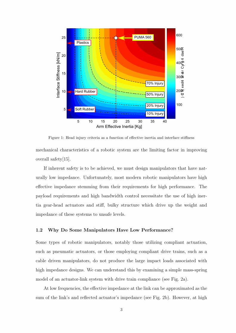
To evaluate the potential for serious injury due to impact we can make use of an
empirical formula developed by the automotive industry to correlate head acceleration
to injury severity known as the Head Injury Criteria (HIC). A simple two degree of
freedom mass-spring model can be used to predict head accelerations that would occur
during an uncontrolled impact. In combination with the HIC index, the predicted
accelerations are used to estimate the likelihood of serious injury occurring during an
impact between a robotic manipulator and a human. For the PUMA 560, an impact
velocity of one meter per second produces a maximum HIC greater than 500, more
than enough to cause injury1 (see Figure 1).
As seen in Figure 1, the addition of a compliant covering can reduce impact
loading by an order of magnitude or more. However, the amount of compliant material
required to reduce impact loads to a safe level can be substantial2. Clearly, adding
large amounts of compliant covering is impractical and does not address the root
cause of high impact loads - namely the large effective inertia of most modern robotic
arms. This hazard can be somewhat mitigated with the use of software and sensor
architectures which monitor and interrupt potential anomalies, and thus reduce the
chance of uncontrolled impact. However, even the most robust system is subject to
unpredictable behavior as a result of electrical, sensor, or software faults. Thus, the
1The HIC index is correlated with the Maximum Abbreviated Injury Scale (MAIS) to provide a mapping from thecalculated HIC values to the likelihood of an occurrence of a specific injury severity level. In Figure 1, HIC valuesand the corresponding likelihood of a concussive injury (or greater) are shown
2For the PUMA robot, the thickness of a compliant cover required is more than five inches, assuming an impactvelocity of 1 meter per second and an allowable maximum HIC index of 100
2
100
200
300
400
500
600
5 10 15 20 25 30 35 40
5
10
15
20
25
In
te
rfa
ce
S
tiffn
e
ss [kN
/m
]
Arm Effective Inertia [Kg]
20% Injury
50% Injury
70% Injury
10% Injury
Plastics
Soft Rubber
PUMA 560
Hard Rubber
H
e
a
d
In
ju
ry C
rite
ria
In
d
e
x (H
IC
)
Figure 1: Head injury criteria as a function of effective inertia and interface stiffness
mechanical characteristics of a robotic system are the limiting factor in improving
overall safety[15].
If inherent safety is to be achieved, we must design manipulators that have nat-
urally low impedance. Unfortunately, most modern robotic manipulators have high
effective impedance stemming from their requirements for high performance. The
payload requirements and high bandwidth control necessitate the use of high iner-
tia gear-head actuators and stiff, bulky structure which drive up the weight and
impedance of these systems to unsafe levels.
1.2 Why Do Some Manipulators Have Low Performance?
Some types of robotic manipulators, notably those utilizing compliant actuation,
such as pneumatic actuators, or those employing compliant drive trains, such as a
cable driven manipulators, do not produce the large impact loads associated with
high impedance designs. We can understand this by examining a simple mass-spring
model of an actuator-link system with drive train compliance (see Fig. 2a).
At low frequencies, the effective impedance at the link can be approximated as the
sum of the link’s and reflected actuator’s impedance (see Fig. 2b). However, at high
3

(Tactual
Tdesired
) Vs Frequency
ω1st mode
Frequency
>180o phase
delay
Bandwidth limited to
<
ω1st mode
3
ωbandwidth
M
a
g
n
itu
d
e
(d)
Jeffective
= (J
link+N
2J
motor)
(b)
Ngear
Jlink
Jmotor
Jmotor
Nmotor
m1
... mi
Jlink
Drive Train Dynamics
k0
k1
ki
(a)
Tactual
Tdesired
Jeffective
= J
link
Jlink
(c)
Jmotor
: drive motor inertia
Nmotor
: drive motor gear ratio
Jlink
: arm link inertia
WHERE:
Jeffective
: effective inertia at output
mi
, ki
: drive-train dynamic elements
Jlink
: arm link inertia
Figure 2: (a) Robotic manipulator compliant drive-train mass-spring model (b) Low frequencyeffective inertia approximation (c) High frequency effective inertia approximation (d) Open-loopTactual /Tdesired magnitude vs frequency
frequencies, which produce the bulk of impact load energy, the effective impedance
is reduced to the link inertia only (see Fig. 2c). For many manipulator systems,
the actuator reflected inertia, with the N 2 amplification due to gear reduction, is
much larger than the link inertia. The attenuation of the actuator’s reflected inertia
through the compliant drive train can significantly reduced impact loads, improving
safety characteristics.
While a compliant actuator or drive train can enhance safety characteristics, the
performance of such systems is limited. The flexible modes of the compliant system
prevents control bandwidths greater than about 1/3 of the fundamental resonant fre-
quency. In addition, attenuation of flexible mode oscillations excited by disturbances
can be difficult to achieve. This results from the phase delay introduced above the
first mode frequency (see Fig. 2d). With the resonant frequencies of many cable
driven manipulators in the range of 10 Hz or less, high performance control of such
systems is difficult if not impossible.
4

1.3 Actuator Characteristics - Obstacle Toward Achieving
Safety and Performance
So why is it so difficult to simultaneously achieve safety and performance characteris-
tics in a single manipulator design? The limitations of current actuation technology
and the manner in which these actuators are used in manipulator designs are to blame.
To understand why, we must examine the characteristics of existing actuation tech-
nology. Currently, only electro-magnetic, hydraulic, and pneumatic actuators have
the power and torque capabilities required for robotic manipulation tasks. Unfortu-
nately, all of these actuation methods have serious deficiencies, limiting their inherent
safety and/or performance characteristics.
Hydraulic actuators, which have the highest torque and power density characteris-
tics of any of the actuation methods, are capable of performing tasks which involve the
application of thousands of Newton-meters of torque and many kilowatts of power
output. However, their very high output stiffness characteristics, which make the
hydraulic actuator essentially a pure position source, can render it very dangerous.
The output impedance, as compared to the driven manipulator and environment,
is virtually infinite, generating very high impact loads during collisions. Typically
these actuators are employed at the joint or through a rigid linkage further increasing
the effective inertia of the manipulator. Thus, manipulators that employ hydraulic
actuators have very poor inherent safety characteristics.
Pneumatic actuators on the other hand can be made very compliant. Due to the
near zero inductance of the compressible gas, their output impedance is low over a
wide frequency range, reducing uncontrolled impact loads to potentially safe levels.
However, pneumatic actuators have very low bandwidth capabilities. Even when
pressure control is implemented (as opposed to conventional flow control), control
bandwidths are limited to less than 20 Hz, which is insufficient for high performance
tasks[7]. Making matters worse, the slow bandwidth capabilities render the large
amount of stored potential energy in the compressible gas a serious hazard. Thus,
while the natural compliance of pneumatic actuation reduces its effective inertia, its
5

low bandwidth characteristics limit the performance characteristics of manipulators
which use them (for the same reasons described in section 1.2).
Primarily as a result of the limitations of pneumatic and hydraulic actuators,
many current human-centered research efforts use manipulation devices that employ
electromagnetic actuation as their primary torque source. The primary limitation of
electromagnetic motors is their relatively low torque and power density. The use of
electromagnetic motors without a torque magnifying reducer is limited to direct drive
systems that must employ large DC torque motors which are heavy and inefficient. To
increase the torque output to useful levels, gear reducers are almost universally em-
ployed when using electromagnetic actuators. Unfortunately, the increase in torque
and power density that results must be traded off against the large increase in re-
flected inertia which increases with the square of the gear reduction. Reduction ratios
employed in most systems more than double the effective inertia of the manipulator,
trading off safety for improved performance.
2 New Actuation Approaches
New actuation approaches have been developed to overcome the safety and perfor-
mance limitations of existing systems. Chief among these are the joint torque control
approach[14] and series elastic actuation[12]. However, for reasons discussed in the
following sections, these approaches do not simultaneously achieve the characteris-
tics necessary for both safety and performance. To address these limitations and
create a unified high-performance and safe robotic manipulator a new actuation ap-
proach, referred to as the Distributed Macro-Mini actuation approach (DM2), has
been proposed[15].
2.1 Joint Torque Controlled Actuation
Joint torque control was developed to eliminate the deleterious effects of nonlinear-
ities and friction inherent in the actuator-transmission systems generally found in
industrial robots. Initial implementations were successful in substantially reducing
6
joint friction effects but wide joint actuation bandwidth was difficult to achieve with-
out actually reducing the friction and non-linearities in the actuator-transmission
system[14, 5, 8].
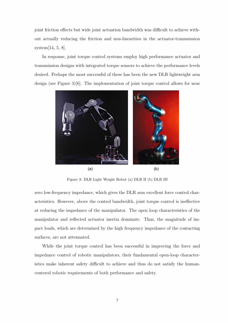
In response, joint torque control systems employ high performance actuator and
transmission designs with integrated torque sensors to achieve the performance levels
desired. Perhaps the most successful of these has been the new DLR lightweight arm
design (see Figure 3)[6]. The implementation of joint torque control allows for near
(a) (b)
Figure 3: DLR Light Weight Robot (a) DLR II (b) DLR III
zero low-frequency impedance, which gives the DLR arm excellent force control char-
acteristics. However, above the control bandwidth, joint torque control is ineffective
at reducing the impedance of the manipulator. The open loop characteristics of the
manipulator and reflected actuator inertia dominate. Thus, the magnitude of im-
pact loads, which are determined by the high frequency impedance of the contacting
surfaces, are not attenuated.
While the joint torque control has been successful in improving the force and
impedance control of robotic manipulators, their fundamental open-loop character-
istics make inherent safety difficult to achieve and thus do not satisfy the human-
centered robotic requirements of both performance and safety.
7
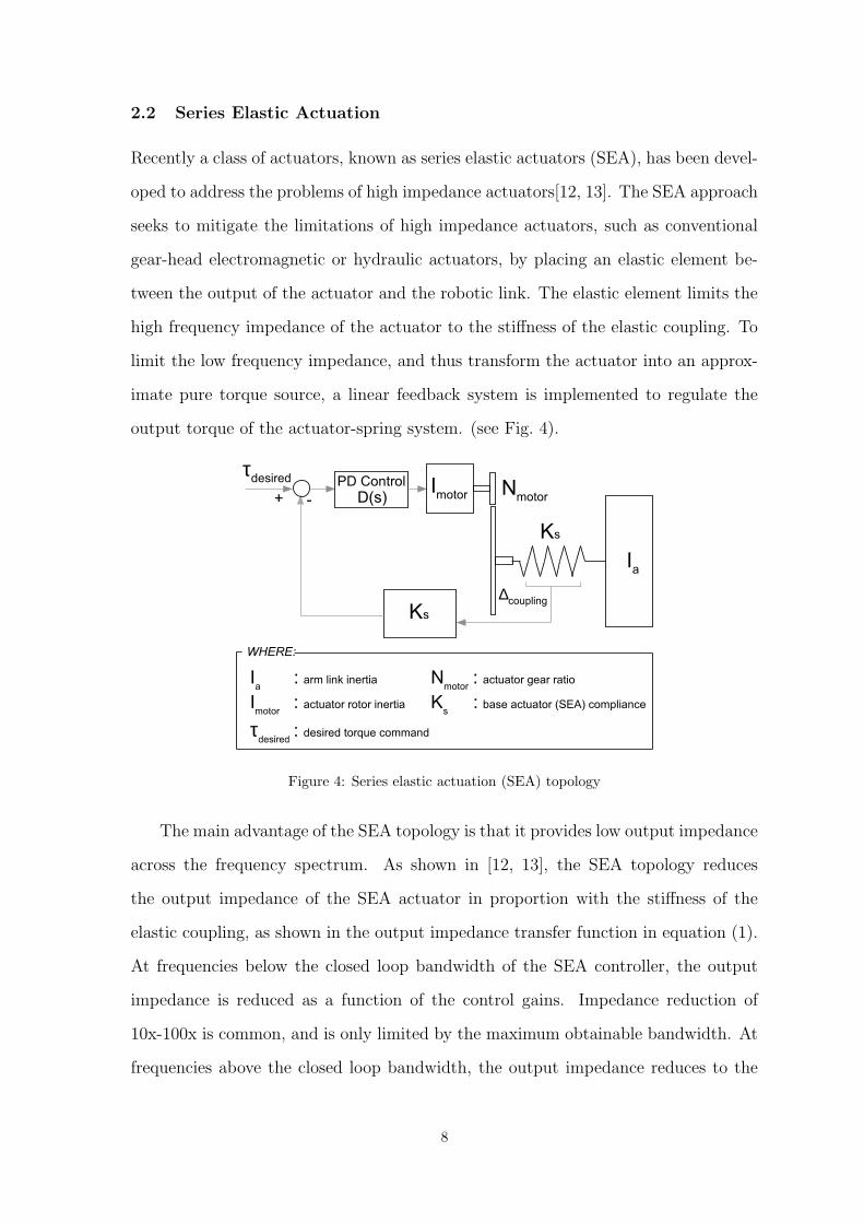
2.2 Series Elastic Actuation
Recently a class of actuators, known as series elastic actuators (SEA), has been devel-
oped to address the problems of high impedance actuators[12, 13]. The SEA approach
seeks to mitigate the limitations of high impedance actuators, such as conventional
gear-head electromagnetic or hydraulic actuators, by placing an elastic element be-
tween the output of the actuator and the robotic link. The elastic element limits the
high frequency impedance of the actuator to the stiffness of the elastic coupling. To
limit the low frequency impedance, and thus transform the actuator into an approx-
imate pure torque source, a linear feedback system is implemented to regulate the
output torque of the actuator-spring system. (see Fig. 4).
Imotor
Nmotor
∆coupling
-
Ks
τdesired
+ D(s)
Ks
Ia
PD Control
Ia
: arm link inertia
Imotor
: actuator rotor inertia
τdesired
: desired torque command
Nmotor
: actuator gear ratio
Ks
: base actuator (SEA) compliance
WHERE:
Figure 4: Series elastic actuation (SEA) topology
The main advantage of the SEA topology is that it provides low output impedance
across the frequency spectrum. As shown in [12, 13], the SEA topology reduces
the output impedance of the SEA actuator in proportion with the stiffness of the
elastic coupling, as shown in the output impedance transfer function in equation (1).
At frequencies below the closed loop bandwidth of the SEA controller, the output
impedance is reduced as a function of the control gains. Impedance reduction of
10x-100x is common, and is only limited by the maximum obtainable bandwidth. At
frequencies above the closed loop bandwidth, the output impedance reduces to the
8
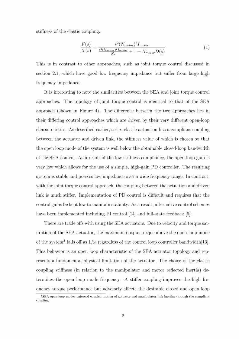
stiffness of the elastic coupling.
F (s)
X(s)=
s2(Nmotor)2Imotor
s2(Nmotor)2Imotor
Ks+ 1 + NmotorD(s)
(1)
This is in contrast to other approaches, such as joint torque control discussed in
section 2.1, which have good low frequency impedance but suffer from large high
frequency impedance.
It is interesting to note the similarities between the SEA and joint torque control
approaches. The topology of joint torque control is identical to that of the SEA
approach (shown in Figure 4). The difference between the two approaches lies in
their differing control approaches which are driven by their very different open-loop
characteristics. As described earlier, series elastic actuation has a compliant coupling
between the actuator and driven link, the stiffness value of which is chosen so that
the open loop mode of the system is well below the obtainable closed-loop bandwidth
of the SEA control. As a result of the low stiffness compliance, the open-loop gain is
very low which allows for the use of a simple, high-gain PD controller. The resulting
system is stable and possess low impedance over a wide frequency range. In contract,
with the joint torque control approach, the coupling between the actuation and driven
link is much stiffer. Implementation of PD control is difficult and requires that the
control gains be kept low to maintain stability. As a result, alternative control schemes
have been implemented including PI control [14] and full-state feedback [6].
There are trade offs with using the SEA actuators. Due to velocity and torque sat-
uration of the SEA actuator, the maximum output torque above the open loop mode
of the system3 falls off as 1/ω regardless of the control loop controller bandwidth[13].
This behavior is an open loop characteristic of the SEA actuator topology and rep-
resents a fundamental physical limitation of the actuator. The choice of the elastic
coupling stiffness (in relation to the manipulator and motor reflected inertia) de-
termines the open loop mode frequency. A stiffer coupling improves the high fre-
quency torque performance but adversely affects the desirable closed and open loop
3SEA open loop mode: unforced coupled motion of actuator and manipulator link inertias through the compliantcoupling
9

impedance characteristics.
The use of a compliant coupling and the closed loop control of the SEA output
torque limits the bandwidth of any task which relies on a series elastic actuator as
its only torque source. This limitation derives from the use of the SEA closed loop
system within a larger, task-specific control loop. As shown in Fig. 5, the design and
resulting stability of the task-specific control loop is dependent on the interaction
between the inner SEA closed loop system and the outer task-specific control loop. If
the outer loop bandwidth approaches the bandwidth of the inner loop, instability is
likely to occur. As a result, the task specific control loop cannot be closed at a rate
faster than the inner loop.
SEA
Controller
SEA
DC Motor
with Gearhead
Kcoupling
∆coupling
τdesired τ
actual
Series Elastic Actuator Inner Loop
Manipulator
Dynamics
Task
Controller
Sensor
Dynamics
Task Specific Outer Control Loop
Figure 5: Nested series elastic actuation and outer task control loops
Tasks such as position control and end-effector impedance control are limited
to a bandwidth that is significantly below the closed loop bandwidth of the SEA
actuator. This is not a major consideration for manipulation systems which do not
require fast dynamics such as walking robots for which the series elastic actuators were
originally developed. However, for tasks requiring high bandwidth control such as high
speed trajectory tracking or high frequency disturbance rejection, the limitations of
the series elastic actuators are prohibitive. Other approaches have been proposed,
such as the use of a nonlinear elastic coupling whose compliance can be changed
through co-activated actuators[2]. Unfortunately, the bandwidth limitations affecting
the series elastic actuator, while mitigated somewhat by the variable compliance, is
still a limiting factor in performance.
10

3 Distributed Macro-Mini Actuation Approach (DM2)
Recently, a new actuation approach, referred to as the distributed macro-mini actua-
tion approach (DM2), has been developed to overcome the safety limitations of joint
torque control and the performance limitations of series elastic actuation[15]. As the
name implies, the DM2 approach employs a pair of actuators, connected in parallel
and distributed to different locations on the manipulator. The effective inertia of the
To
rq
u
e
M
a
g
n
itu
d
e
Frequency
+
Parallel Actuation
Base Actuation
(Low Frequency)
Joint Actuation
(High Frequency)
PID
PID
Base Actuation
(Low Frequency)
Distributed Actuation
Lightweight
Structure
+ Cable
Drivetrain
Joint Actuation
(High Frequency)
Elastic Coupling
+ FeedbackShoulder Joint
Actuator
Elbow Joint
Actuator
Elbow Base
Actuator
Shoulder
Base Actuator
AND
(a) (b)
Figure 6: Distributed Macro-Mini (DM2) actuation approach (a)Partition of torque into low andhigh frequency (parallel) components (b) Distributed actuation: Large, low frequency actuators arelocated at base. Small, high frequency actuators are located at the joints
overall manipulator is substantially reduced by isolating the reflected inertia of the
actuator while greatly reducing the overall weight of the manipulator. Performance is
maintained with small actuators collocated with the joints. Our approach partitions
the torque generation into low and high frequency components and distributes these
components to the arm location where they are most effective. The overall approach
is shown in Fig. 6
The first part of the DM2 actuation approach is to divide the torque generation
into separate low and high frequency actuators whose torque sum in parallel. The
effectiveness of this approach can be seen clearly when one considers that most manip-
11
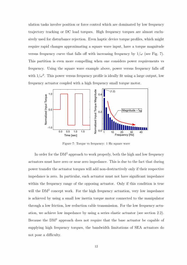
ulation tasks involve position or force control which are dominated by low frequency
trajectory tracking or DC load torques. High frequency torques are almost exclu-
sively used for disturbance rejection. Even haptic device torque profiles, which might
require rapid changes approximating a square wave input, have a torque magnitude
versus frequency curve that falls off with increasing frequency by 1/ω (see Fig. 7).
This partition is even more compelling when one considers power requirements vs
frequency. Using the square wave example above, power versus frequency falls off
with 1/ω2. This power versus frequency profile is ideally fit using a large output, low
frequency actuator coupled with a high frequency small torque motor.
ω1Magnitude ~
0.0
0.2
0.4
1 10 20 30 40
Frequency [Hz]
0.0 0.5 1.0 1.5
Time [sec]
-1.0
0.0
1.0
N
o
rm
a
lize
d
In
p
u
t To
rq
u
e
(1.2)
N
o
rm
a
lize
d
In
p
u
t To
rq
u
e
M
a
g
n
itu
d
e
Figure 7: Torque vs frequency: 1 Hz square wave
In order for the DM2 approach to work properly, both the high and low frequency
actuators must have zero or near zero impedance. This is due to the fact that during
power transfer the actuator torques will add non-destructively only if their respective
impedance is zero. In particular, each actuator must not have significant impedance
within the frequency range of the opposing actuator. Only if this condition is true
will the DM2 concept work. For the high frequency actuation, very low impedance
is achieved by using a small low inertia torque motor connected to the manipulator
through a low friction, low reduction cable transmission. For the low frequency actu-
ation, we achieve low impedance by using a series elastic actuator (see section 2.2).
Because the DM2 approach does not require that the base actuator be capable of
supplying high frequency torques, the bandwidth limitations of SEA actuators do
not pose a difficulty.
12

The second part of the DM2 actuation approach, which differs from previous at-
tempts at coupled actuation[11], is to distribute the low and high frequency actuators
to locations on the manipulator where their effect on contact impedance is minimized
while their contribution to control bandwidth is maximized. This is achieved by lo-
cating the low frequency series elastic actuator remotely from the actuated joint. This
is particularly advantageous as the low frequency components of most manipulation
tasks are considerably larger in magnitude than the high frequency components and
consequently require a relatively large actuator. Locating the large SEA actuator at
the base significantly reduces the weight and inertia of the manipulator. The high
frequency actuators are located at the manipulator joints and connected through a
stiff, low friction transmission, providing the high frequency torque components that
the low frequency base actuators cannot. The high frequency torque actuator must
be connected to the joint inertia through a connection which produces a high primary
mode vibration frequency. By locating the actuator at the joint and by using a low
inertia servomotor, we can achieve this high bandwidth connection with a minimum
amount of weight and complexity.
The DM2 approach is analogous to the design of robotic manipulators for use
in zero gravity. Under such conditions, gravity induced torques do not exist. Joint
actuators provide torques related only to the task, such as trajectory tracking and dis-
turbance rejection, both of which are primarily medium to high frequency in content.
We achieve the zero gravity analogy by compensating for gravity torques and low
frequency torques using the low frequency actuators located at the base of the ma-
nipulator. With the effects of gravity and low frequency torques compensated, joint
torque requirements become similar to those encountered by a zero gravity robotic
manipulator. However, unlike robotic manipulators designed for space applications,
the DM2 joint actuators do not require a large gear reducer to achieve the required
torque and power densities.
13

3.1 DM2 Actuation Control Approach
Perhaps the most challenging aspect of a DM2 implementation is the development
of a control approach which leverages the characteristics of the parallel actuator
structure while dealing with the unique control challenges associated with the use of
low impedance actuation.
At the joint level, the DM2 approach is essentially a dual-input single output
system. The redundant actuators provide an additional degree of freedom which can
be used in optimizing system performance while minimizing actuation effort. For
example, in the case of trajectory tracking, we can use LQR control techniques to
obtain an optimum control law based on minimizing control effort and tracking er-
ror. The low and high frequency actuation effort partitioning can be accomplished
in a similar manner. However, this type of control structure is specific to a given
task, in this case to trajectory tracking, and does not provide a black-box interface
to the actuation similar to the use of a single actuator. In particular, for applications
involving a number of different control modes, such as free-space motion with con-
tact transitions, or for applications requiring a low-impedance torque source, such as
haptics or tele-robotic master devices, we desire an actuation control scheme which
allows the use of the parallel actuation system as a single torque source.
3.1.1 Near Perfect Torque Source
As such, our control approach seeks to exploit the DM2 actuation’s unique character-
istics to construct a near perfect torque source. The characteristics of a perfect torque
source, consisting of zero output impedance and infinite control bandwidth, would en-
able a manipulator to possess the characteristics necessary for both inherent safety
and high performance tasks. While a perfect torque source is impossible to achieve,
a near perfect torque source, with low output impedance relative to the driving load
and high bandwidth torque capability offers much of the same advantages.
A physical schematic of the control structure along with an equivalent block
diagram representation are shown in Figures 8 and 9, respectively. The transfer
14

function of the control structure shown in Figure 9 has unity gain and zero phase
over all frequencies ( Tactual(s)Tdesired(s)
= 1). A simplified representation, shown in Figure 10,
demonstrates how the control approach utilizes the low frequency base actuator’s low
pass filter characteristics to partition the control torques into low and high frequency
components.
Ib
Nb
∆coupling
-
Ks
τdesired
+
PID
Ks
Ij
Base Low Frequency (Series Elastic) Actuator Joint High
Frequency Actuator
Ia
Ia
: arm link inertia
Ib
: base actuator rotor inertia
Ij
: joint actuator rotor inertia
Nb
: base actuator gear ratio
Nj
: joint actuator gear ratio
Ks
: base actuator (SEA) compliance
WHERE:
Nj
Figure 8: DM2 Actuation and control topology (single DOF)
(Ia
+ N
j
Ij
)s2
1
2
Ks
Ib
s
2
1
Nb
1
+
-
+
+
+
-
Nb
1
+
-
PID
τactual
τdesired
Figure 9: DM2 Actuation and control block diagram representation (single DOF)
By using the actual measured torque output from the low frequency base actuators
in combination with the desired torque, we automatically compensate for the non-
ideal behavior of the base actuators. Assuming that the smaller joint actuators can
produce this torque, the combined torques sum is a perfect realization of the desired
15

torque. The frequency partitioning can be clearly seen if we rearrange the structure
in Fig. 10a into a pure parallel structure, as shown in Fig. 10b. As seen in Fig. 10b,
the base actuator’s transfer function falls off above it’s closed-loop bandwidth, wbase,
while the equivalent joint actuator’s transfer function approximates a double lead
filter, which adds phase to the combined system above the open loop mode frequency,
ws, and attenuates the DC and low frequency components commanded to the high
frequency actuator.
G(s)base closed-loop
Frequency
Frequency
1 - G(s)base closed-loop
Joint Actuation
Base Actuation
τdesired
+ τactual
+
ωbase
ωs
(b)
(a)
G(s)base
closed-loop
G(s)joint
τdesired
+
τactual+
+-
Joint Actuation
(ωbw
~ 200Hz)
Base Actuation (ωbw
~ 20Hz)
Figure 10: (a) DM2 actuation control structure (G(s)base−closed−loop: Base actuator closed looptransfer function. G(s)joint: Joint actuator transfer function) (b) Equivalent parallel structure
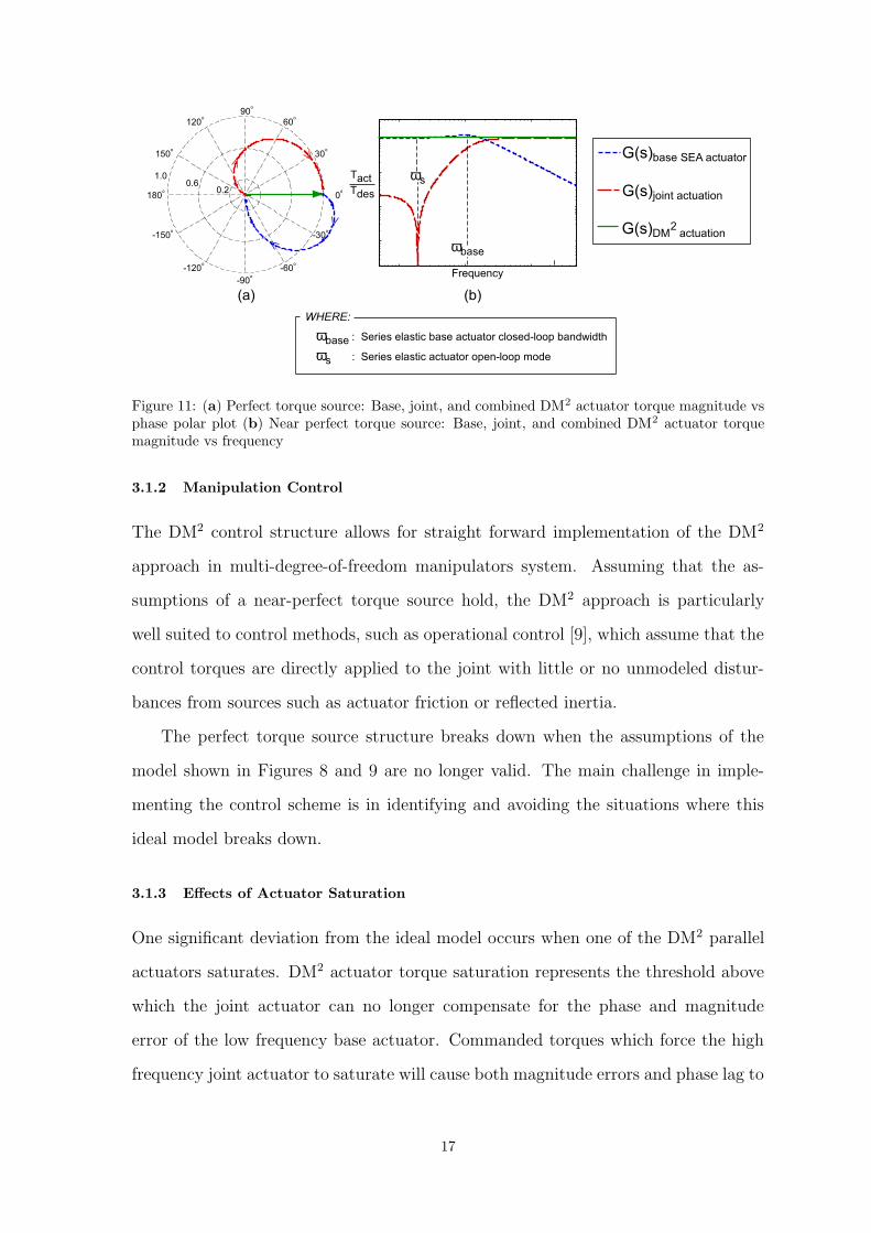
The combined actuator control structure creates a perfect torque source in the
linear sense, where the torques sum to unity magnitude and zero phase, as seen in
Fig. 11a and 11b. Thus, by using the simple control structure describe above we
can create a unified actuator with the desirable characteristics of low impedance -
necessary for inherent safety, and high bandwidth torque control - necessary for high
performance.
16
G(s)joint actuation
G(s)DM actuation
G(s)base SEA actuator
2
(b)
Frequency
Tact
Tdes
ωbase
ωs
0
o
30
o
60
o
-30
o
-60
o
150
o
120
o
-150
o
-120
o
180
o
90
o
-90
o
0.2
0.6
1.0
(a)
ωbase
: Series elastic base actuator closed-loop bandwidth
ωs
: Series elastic actuator open-loop mode
WHERE:
Figure 11: (a) Perfect torque source: Base, joint, and combined DM2 actuator torque magnitude vsphase polar plot (b) Near perfect torque source: Base, joint, and combined DM2 actuator torquemagnitude vs frequency
3.1.2 Manipulation Control
The DM2 control structure allows for straight forward implementation of the DM2
approach in multi-degree-of-freedom manipulators system. Assuming that the as-
sumptions of a near-perfect torque source hold, the DM2 approach is particularly
well suited to control methods, such as operational control [9], which assume that the
control torques are directly applied to the joint with little or no unmodeled distur-
bances from sources such as actuator friction or reflected inertia.
The perfect torque source structure breaks down when the assumptions of the
model shown in Figures 8 and 9 are no longer valid. The main challenge in imple-
menting the control scheme is in identifying and avoiding the situations where this
ideal model breaks down.
3.1.3 Effects of Actuator Saturation
One significant deviation from the ideal model occurs when one of the DM2 parallel
actuators saturates. DM2 actuator torque saturation represents the threshold above
which the joint actuator can no longer compensate for the phase and magnitude
error of the low frequency base actuator. Commanded torques which force the high
frequency joint actuator to saturate will cause both magnitude errors and phase lag to
17

occur, invalidating the perfect torque source characteristics of the combined parallel
actuation. This effect is illustrated in Fig. 12a and 12b.
0
o
30
o
60
o
-60
o
150
o
120
o
-150
o
-120
o
180
o
90
o
-90
o
Saturation
induced
phase lag
Increasing
Saturation
100
10-1
-100
Frequency
M
a
g
n
itu
d
e
P
h
a
se
[d
e
g
]
-50
0
Increasing
Saturation
Saturation
induced
phase lag
(b)(a)
G(s)joint actuation G(s)
DM actuation
2G(s)base SEA actuator
Figure 12: Breakdown of perfect torque source due to saturation (a) Base, joint (with saturation),and resulting DM2 actuator torque magnitude vs phase polar plot (b) Bode plot of DM2 actuatortorque with joint actuator saturation
In Fig. 12a and 12b, the frequency response of the base series elastic actuator, the
joint actuator, and the combined DM2 actuator is shown on a polar plot of magnitude
versus frequency (Fig. 12a) and as a bode plot (Fig. 12b). The effect of saturation
can be seen as both magnitude and phase errors in the resulting parallel actuation
response. As the joint actuator approaches complete saturation, the combined parallel
actuator’s response approaches that of the single base series elastic actuator with its
lower bandwidth constraints. This is particularly problematic in that a task control
loop, such as position tracking, which under normal conditions is stable, can become
unstable as a result of a torque command which exceeds the capabilities of the smaller
joint actuator.
As a result, the controller must prevent saturation of the joint actuator from
occurring. This can be accomplished by simply limiting the control input. This
approach is taken when there is no outer task closed loop, such as with simple haptic
rendering where the desired torque is a function of manipulator position alone and no
effort is made to compensate the system output. In the case when there is a control
loop wrapped around the DM2 actuation, the control gains must be reduced or the
18

control input limited to avoid saturation. As such, the avoidance of saturation poses
a limit on the ultimate performance of a DM2 actuated manipulator. Fortunately, as
discussed in section 3, the torque requirement of the high frequency joint actuator
is substantially less than the low frequency base actuators. Thus, avoidance of joint
actuator saturation can be achieved with proper sizing of the joint actuator with
respect to the given manipulator tasks.
3.1.4 Manipulator Control With Low Impedance Actuation
Another deviation from the ideal model, which can have a significant effect on per-
formance, is the existence of compliance in the drive train between the manipulator
link and the joint actuator. While the joint actuator has a relatively stiff single-stage
transmission design, some level of compliance is unavoidable. The drive train com-
pliance in combination with the low reflected inertia of the joint actuator produces
low frequency oscillations which can limit closed-loop performance. This effect can
be understood by augmenting the DM2 model in Figure 8 to include joint actuator
drive-train compliance (see Figures 13 and 14).
Ib
Nb
∆coupling
-
Ks
τdesired
+
PID
Ks
IJ
Base Low Frequency (Series Elastic) Actuator Joint High Frequency Actuator
(Drive-Train Compliance Included)
Ia
Kj
Nj
Ia
: arm link inertia
Ib
: base actuator rotor inertia
Ij
: arm link inertia
Kj
: joint actuator drive-train compliance
Nb
: base actuator gear ratio
Nj
: joint actuator gear ratio
Ks
: base actuator (SEA) compliance
WHERE:
Figure 13: Augmented DM2 actuation and control topology (single DOF). Joint actuator drive-traincompliance included.
The transfer function of the system shown in Figure 13 no longer represents a pure
19

Ij
s
2
1
Nj
1
Ia
s
2
1
Kj
Ks
Ib
s
2
1
Nb
1
+
-
+
-
+
-
Nj
1
+
+
+
-
Nb
1
+
-
PID
Nj
1
τactual
τdesired
Figure 14: Augmented DM2 actuation and control block diagram representation (single DOF). Jointactuator drive-train compliance included.
torque source. The addition of the oscillatory pole, due to the drive train compliance,
is clearly visible on the bode plot on the system transfer function in Figure 15. The
presence of the flexible mode is of no surprise and, at first glance, does not seem
to pose a significant problem. The relatively high frequency of the oscillatory mode
would suggest that the proper choice of gains will provide adequate performance while
avoiding excitation of the oscillatory pole.
-30
-20
-10
0
10
20
30
Magnitude (dB)
(s)desired
τ(s)
actualτ
10
0
10
1
10
2
10
3
Frequency (rad/sec)
-180
-135
-90
-45
0
Phase (Deg)
(s)desired
τ(s)
actualτ
Oscillatory Mode
Figure 15: Bode plot of augmented DM2 actuation and control block diagram representation (singleDOF). Joint actuator drive-train compliance included.
However, as a result of the low reflected inertia of the DM2 actuation approach,
the ratio of joint actuator’s reflected inertia to driven link inertia is very small, typi-
20

cally 1:10 or less. This large mismatch between actuator and drive train inertia can
cause serious low frequency oscillations to occur when position or velocity feedback
is introduced, limiting the maximum task control loop bandwidth achievable. For
successful implementation of the DM2 approach, it is important to fully understand
this phenomenon and to develop techniques to address and compensate for its effects.
We can more clearly understand this phenomenon using a simplified model of
the DM2 system which includes the drive train compliance but ignores the coupling
with the low frequency base actuator. Figure 16a and equation (2) show the assumed
model and its uncompensated open-loop transfer function.
θdes
+ −D(s)
θj
Ij
Ia
τj
Kj
(a)
θa
collocated feedback
θdes
+ −D(s)
θj
Ij
Ia
τj
Kj
(b)
θa
non-collocated feedback
Ia
: arm link inertia
Ij
: joint actuator rotor inertia
Kj
: joint actuator drive-train compliance
τj
: joint actuator torque
WHERE:
θj
: joint actuator position
θa
: arm link position
Figure 16: Spring-mass model of joint actuator and driven link Inertias (a) Collocated control (b)Non-collocated control
In many servo-systems, including robotics, the actuator and link inertias are
matched or nearly matched to achieve optimum power and acceleration transfer from
motor to load. In this situation, the poles and zeros of the transfer function, given
by (4), are approximately equal in frequency.
θj(s)
τj(s)=
s2Ia + Kj
s2(s2IaIj + Kj(Ia + Ij))(2)
21

θa(s)
τj(s)=
Kj
s2(s2IaIj + Kj(Ia + Ij))(3)
ωzero =
√
Kj
Ia
and ωpole =
√
√
√
√
Kj(Ij + Ia)
IaIj
(4)
However, in a system employing low impedance actuation, the zero’s frequency
can be an order of magnitude below the frequency of the flexible mode pole. This
large separation amplifies the flexible mode peak by a factor approximately equal to
the ratio of drive link to motor inertias (see Fig. 17).
Collocated Position Control
ωzero
ωpoleInertia Ratio
Ij/I
a
10
2
10.5 0.2 0.1 0.05
where Ieff
= Ij + I
as
2Ieff
1
s2Ij
1
Amplication
Ij + I
a
Ij
M
a
g
n
itu
d
e
(s)j
τ(s)j(n
o
rm
a
lize
d
)
θ
θj
Ij
Ia
τj
(s)j
τ(s)
jθ
Figure 17: Open loop transfer function of collocated motor position control: Amplification of oscil-latory pole due to mismatched actuator-link inertia
This effect severely limits the achievable closed loop bandwidth and thus perfor-
mance in general. The effect can be quite puzzling considering that the flexible mode
frequency can be very high - an order of magnitude or more above the open loop
crossover frequency - and still cause excessive oscillations in the closed loop response.
Only when one considers the zero, whose frequency is affected by the much larger
drive link inertia, does it become clear why the problem exists.
Another way to analyze the problem is to examine the symmetric root locus (see
Figure 18) of the system shown in Fig. 16a. When the ratio of joint motor rotor
inertia to arm inertia, Ij/Ia, is close to 1:1, the oscillatory poles are drawn toward
the transmission zeros as the gain is increased, reducing their residues which reduces
the magnitude of oscillations and allows for larger closed loop gains. However, when
the motor inertia, Ij, is much less than the arm inertia, Ia, the transmission zeros
are located too far from the oscillatory poles to have a stabilizing effect and instead
22
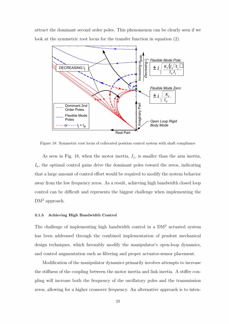
attract the dominant second order poles. This phenomenon can be clearly seen if we
look at the symmetric root locus for the transfer function in equation (2).
Flexible Mode Pole:
( )ja
jat
IIIIKi +±
Flexible Mode Zero:
a
j
IKi±
Open Loop Rigid
Body Mode
D
e
cre
a
in
g
Ij
In
cre
a
sin
g
ω po
le
Real Part
Im
a
g
in
a
ry P
a
rt
DECREASING Ij
Dominant 2nd
Order Poles
Flexible Mode
Poles
or Ij = I
a
Figure 18: Symmetric root locus of collocated position control system with shaft compliance
As seen in Fig. 18, when the motor inertia, Ij, is smaller than the arm inertia,
Ia, the optimal control gains drive the dominant poles toward the zeros, indicating
that a large amount of control effort would be required to modify the system behavior
away from the low frequency zeros. As a result, achieving high bandwidth closed loop
control can be difficult and represents the biggest challenge when implementing the
DM2 approach.
3.1.5 Achieving High Bandwidth Control
The challenge of implementing high bandwidth control in a DM2 actuated system
has been addressed through the combined implementation of prudent mechanical
design techniques, which favorably modify the manipulator’s open-loop dynamics,
and control augmentation such as filtering and proper actuator-sensor placement.
Modification of the manipulator dynamics primarily involves attempts to increase
the stiffness of the coupling between the motor inertia and link inertia. A stiffer cou-
pling will increase both the frequency of the oscillatory poles and the transmission
zeros, allowing for a higher crossover frequency. An alternative approach is to inten-
23

tionally increase the motor’s inertia, thereby reducing the frequency of the oscillatory
poles to the frequency of the zeros. However, this approach is only useful when the
motor and link inertias differ by less than approximately a factor of 2. Otherwise,
the required increase in motor inertia is excessively large and severely reduces the
acceleration capability of the system. Regardless, in the case of low impedance ac-
tuation, a large increase in actuator inertia would substantially increase the reflected
inertia of the actuator, adversely effecting its safety characteristics and thus can not
be considered for human-friendly robotic systems. Thus, mechanical modifications
are limited to those that increase the frequency of the transmission zeros, such as
stiffening the motor transmission or reducing the driven link inertia
In addition to mechanical modifications and control signal filtering[4], a some-
what surprising method to deal with the low frequency oscillations associated with
low impedance actuation is to change the control topology from collocated to non-
collocated control. We can understand this by examining the open-loop transfer
function of a simple mass-spring model of an actuator-link system which employs
non-collocated control. Fig. 16b and equation (3) show the assumed model and its
associated transfer function. At first glance, this seems counter intuitive since in most
cases the stabilizing effect of the zeros associated with collocated control are beneficial
and allow for more aggressive gains. However, in the case of large inertia mismatch,
the collocated control zero is the main cause of the problem. A comparison of peaking
amplitude (see Fig. 19) shows that for large mismatches the non-collocated control
may be better than a collocated approach. Of course, this doesn’t take into account
the tendency of the oscillatory poles to become unstable, and special care must be
taken to insure their stability, such as using of a notch filter or a gain stabilizing
lag network[3]. With this consideration, we can conservatively assume that when
using non-collocated control we can achieve a cross-over frequency as high as 1/5 of
the flexible mode frequency. With this assumption, we can see from Fig. 19 that
when the joint motor inertia is much less than the arm inertia (Ij/Ia < 10) the use
of non-collocated control allows for a higher closed loop bandwidth than collocated
24

control. This, in fact, has been shown to be the case on a two axis testbed, where
the motor-link inertia ratios range from 1:50 to less than 1:100.
(s)j
τ(s)
a (normalized)θ
Collocated Open
Loop Transfer
Function
(s)j
τ(s)
j (normalized)θ
Non-Collocated
Open Loop
Transfer Function
Frequency
10 0.05
N
o
rm
a
lize
d
M
a
g
n
itu
d
e
Inertia Ratio:
Ij/I
aCollocated Control:
Oscillatory Mode Peaking
Non-Collocated Control:
Oscillatory Mode Peaking
Figure 19: Variation of peaking amplitude for collocated and non-collocated position control forvarying motor to load inertia ratios, Ij/Ia
3.2 Promising Results: Safety and Performance
To demonstrate the effectiveness of the DM2 approach, we have designed and built
a two axis prototype robotic arm which incorporates the important characteristics of
the DM2 approach. The overall design approach is shown in Figure 20. Preliminary
Base Actuator
Servo Motor and
Harmonic Drive
Adjustable
Stiffness
Coupling
LOHET
Magnet
Deflection
Sensor
Elbow Joint Base Actuator
(shoulder actuator not shown for clarity)
Elbow Joint
Shoulder Joint
Internal
Drive Cables
Drive Idler
Pulley
Single Stage
Cable Drive
Base Actuator
Drive Pulley
Joint Actuator
Servo Motor
(section view)
Figure 20: Two axis DM2 prototype
experimental and simulation results have demonstrated the effectiveness of the DM2
25

approach. The reduction in impact loading by an order of magnitude, as compared to
conventional joint actuated manipulators, substantially improves the inherent safety
of the manipulator. In the case of a two-axis prototype developed at Stanford (see
Figure 20), the effective joint inertia was reduced by almost a factor of ten. We can
use the effective inertia, graphically illustrated as a belted ellipsoid[10], to calculate
the impulse due to impact at any point on the manipulator. To demonstrate the
effectiveness of the DM2 approach in reducing impact loads, Figure 21 shows the
normalized impact impulse for two cases of end-point load (Pload) for a two degree
of freedom planar manipulator. The impact impulse reduction increases rapidly with
Normalized
impulse vector
Iy
Ix
collision impulse
magnitude
collision velocity
direction
(a) Normalized Impulse Vector
Conventional
Joint Actuation
Conventional
Cable Drive
DM2
Approach
Pload
= 1 [kg] Pload
= 10 [kg]
Ix
1.0
Iy
Ix
1.0
Iy
(b) Normalized Impact Impulse vs Collision Velocity Direction
(c) Normalized Impact Impulse Load Comparison
Pload
= 1 [kg] Pload
= 10 [kg]
Conventional Joint Actuation
Conventional Cable Drive
DM2 Approach
1.0
0.8
0.6
0.4
0.2
0
N
o
rm
a
lize
d
Im
p
u
lse
L
o
a
d
10x Reduction
5x Reduction
Figure 21: Comparison of impulse load due to impact for various actuation concepts. (a) Normalizedimpulse vector: Impulse due to collision of manipulator end effector with rigid object. Impulsemagnitude changes with angle due to variation of end-effector effective inertia as a function ofimpact direction. (b) Normalized impact impulse vs collision velocity direction for various actuationconcepts and values of end-point load (Pload). (c) Comparison of normalized impact impulse loadfor various actuation concepts and values of end-point load (Pload). Impulse values are normalizedby impact velocity and maximum effective inertia.
increasing load, as the required increase in actuator torque capability affects the
reflected inertia of the conventional and cable-driven manipulators while minimally
affecting the reflected inertia of the distributed-parallel approach. While this is just
26
a illustrative example, we see that in combination with a light weight structure and
compliant covering, this new actuation approach can be used to design a manipulator
that reduces impact loads substantially, thus ensuring inherent safety.
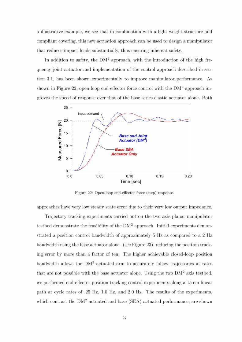
In addition to safety, the DM2 approach, with the introduction of the high fre-
quency joint actuator and implementation of the control approach described in sec-
tion 3.1, has been shown experimentally to improve manipulator performance. As
shown in Figure 22, open-loop end-effector force control with the DM2 approach im-
proves the speed of response over that of the base series elastic actuator alone. Both
25
20
15
10
5
0
0.100.05 0.150.0 0.20
M
e
a
su
re
d
F
o
rce
[N
]
Time [sec]
Base SEA
Actuator Only
Base and Joint
Actuator (DM )2
input comand
Figure 22: Open-loop end-effector force (step) response.
approaches have very low steady state error due to their very low output impedance.
Trajectory tracking experiments carried out on the two-axis planar manipulator
testbed demonstrate the feasibility of the DM2 approach. Initial experiments demon-
strated a position control bandwidth of approximately 5 Hz as compared to a 2 Hz
bandwidth using the base actuator alone. (see Figure 23), reducing the position track-
ing error by more than a factor of ten. The higher achievable closed-loop position
bandwidth allows the DM2 actuated arm to accurately follow trajectories at rates
that are not possible with the base actuator alone. Using the two DM2 axis testbed,
we performed end-effector position tracking control experiments along a 15 cm linear
path at cycle rates of .25 Hz, 1.0 Hz, and 2.0 Hz. The results of the experiments,
which contrast the DM2 actuated and base (SEA) actuated performance, are shown
27

Desired Angle [rad]
-0.10 -0.05 0.0 0.05 0.10
-0.10
-0.05
0.0
0.05
0.10
A
ctu
a
l A
n
g
le
[ra
d
] 2 Hz bandwidth
tracking error ~ .04 rad
5 Hz bandwidth
tracking error ~ .004 rad
Shoulder: Desired vs Acutal Angle
BASE SEA
ACTUATOR ONLY
BASE + JOINT
Desired Angle [rad]
-0.10 -0.05 0.0 0.05 0.10
-0.10
-0.05
0.0
0.05
0.10
A
ctu
a
l A
n
g
le
[ra
d
]
5 Hz bandwidth
tracking error ~ .005 rad
Elbow: Desired vs Acutal Angle
BASE + JOINT
2 Hz bandwidth
tracking error ~ .06 rad
BASE SEA
ACTUATOR ONLY
Figure 23: Comparison of position tracking performance using base actuation only with combinedbase and joint actuation (DM2)
in Figure 24. The DM2 actuated testbed showed good tracking control for all three
cases, with only a small amount of amplitude and phase distortion occurring during
the 2.0 Hz rate experiment. The same experiment performed using the base actu-
ators alone produced significant tracking error. During the 1.0 Hz and 2.0 Hz rate
experiments, significant phase and amplitude distortion were observed.
0.25 Hz Scan
0
4
8
-4
-8
-2
2
6
-6
0
4
8
-4
-8
-2
2
6
-6
0
4
8
-4
-8
-2
2
6
-6
X
P
o
sitio
n
[m
]
X
P
o
sitio
n
[m
]
X
P
o
sitio
n
[m
]
X
P
o
sitio
n
[m
]
X
P
o
sitio
n
[m
]
X
P
o
sitio
n
[m
]
1.0 Hz Scan 2.0 Hz Scan
BASE
ACTUATOR
ONLY
DM
(BASE/JOINT
ACTUATOR)
2
Desired end-effector x-position
End-effector x-position (Base only actuation)
End-effector x-position (Base and joint actuation)
End-Effector Trajectory Tracking: Linear Path (~15 cm full scale)
Figure 24: End effector position tracking control experimental results.
3.3 Distributed Macro-Mini Implementation
Finally, a few words should be said about the implementation of a DM2 actuated
robotic system. The DM2 approach is essentially a trade off between safety, perfor-
mance, and design complexity. However, this design trade is not necessarily a zero-
28

Distributed Macro-
Mini Actuation
Single Actuator
Inner DOFs
(DM2 Actuation)
Outer DOFs
(Single Actuators)
Figure 25: Implementation of DM2 actuation for multi-DOF manipulator
29
sum game. Recall that the primary reason for the introduction of our new actuation
approach was to (1) reduce contact impedance and (2) maintain task performance
levels. If the task is performed by a manipulator’s end effector, then high frequency
torque and force capabilities need only be provided at the end effector. As shown
in [10], the dynamics of a redundant manipulator is bounded by the dynamics of the
outermost degrees of freedom which span the task space. In the case of a redundant
manipulation system, such as a dual manipulator - mobile base’s system depicted in
Figure 25, the mobile base degrees of freedom need not employ our new actuation
approach to maintain task performance levels which, due to the redundancy of the
system, are bounded by the outer six degrees of freedom. Another possible approach
is to design the wrist such that required task torques are small, as would be the case
for a compact wrist design. In this case, the wrist actuation could be provided by
smaller conventional EM actuators. The large DC and low frequency torques pro-
vided by the base actuators of the DM2 approach would not be required. The higher
impedance of the wrist actuators would not compromise safety because impact loads
would be limited by the inner three degrees of freedom. Thus, our new human friendly
actuation approach can be implemented in a manner which maximizes the safety and
performance characteristics while minimizing the additional complexity associated
with its dual actuation approach.
Summary
We have presented a new actuation concept for human-friendly robot design, referred
to as Distributed Macro Mini Actuation (DM2). The new concept (DM2) was demon-
strated on a two degree of freedom prototype robot arm that we designed and built
to validate our approach. The new actuation approach substantially reduces the im-
pact loads associated with uncontrolled manipulator collision by relocating the major
source of actuation effort from the joint to the base of the manipulator. High fre-
quency torque capability is maintained with the use of small, low inertia servomotors
collocated at the joints. The servomotors, integrated with a low reduction, low friction
30
cable transmission, provide the high frequency torque required for high performance
tasks while not significantly increasing the combined impedance of the manipulator-
actuator system. The low output impedance and complete frequency coverage of the
new actuation approach allows the combined manipulator system to approximate a
pure torque source. This in turn allows for very good open loop joint torque control
over a wide frequency range. Initial experimental and simulation results validate the
DM2 approach.
Acknowledgments
This material is based upon work supported by the National Science Foundation
under Grant No. EIA-9977717, the support of which is gratefully acknowledged.
In addition, the authors would like to thank our colleagues Gunter Neimeyer4 and
Kenneth Waldron4 for their helpful insights and discussion in preparing this paper.
References[1] Technical challenge for dependable robotots in human environments. In G. Giralt and P. Corke, editors,
Proc. of IARP/IEEE-RAS Joint Workshop, Sole, Korea, 2001.
[2] A. Bicchi, L. Rizzini, and G. Tonietti. Compliant design for intrinsic safety: General issues and prelim-inary design. In Proc. of the Intl. Conf. on Intelligent Robots and Systems, 2001.
[3] R. H. Cannon and E. Schmitz. Initial experiments on the end-point control of a flexible one-link robot.Intl. Journal of Robotics Research, 3(3):62–75, 1984.
[4] G. Ellis and R.D. Lorenz. Resonant load control methods for industrial servo drives. In Proc. of IEEEIndustry Applications Society, Rome, Italy, 2000.
[5] G. Hirzinger, A. Albu-Schaffer, M. Hahnle, I. Schaefer, and N. Sporer. A new generation of torquecontrolled light-weight robots. In Proc. of the Intl. Conf. on Robotics and Automation, 2001.
[6] G. Hirzinger, N. Sporer, A. Albu-Schaffer, M. Hahnle, and A. Pascucci. DLR’s torque-controlled lightweight robot iii - are we reaching the technolotical limits now? In Proc. of the Intl. Conf. on Roboticsand Automation, pages 1710–1716, 2002.
[7] John Hollerbach, Ian Hunter, and John Ballantyne. A Comparative Analysis of Actuator Technologiesfor Robotics, pages 299–342. MIT Press, Cambridge, Massachussetts, 1991.
[8] Robert Holmberg, Sanford Dickert, and Oussama Khatib. A new actuation system for high-performancetorque-controlled manipulators. In Proc. of the Ninth CISM-IFToMM Symp. on the Theory and Practiceof Robots and Manipulators, pages 285–292, Udine Italy, September 1992.
[9] Oussama Khatib. A unified approach for motion and force control of robot manipulators: The oper-ational space formulation. IEEE Journal of Robotics and Automation, YEAR = 1987, VOLUME =RA-3, NUMBER = 1, PAGES = 43-53, MONTH = February, NOTE = .
[10] Oussama Khatib. Inertial properties in robotic manipulation: An object-level framework. Intl. Journalof Robotics Research, 14(1):19–36, February 1995.
[11] J.B. Morrel. Parallel Coupled Micro-Macro Actuators. PhD thesis, Massachusetts Institute of Technol-ogy, Cambridge, MA, 1996.
[12] Gill Pratt and Matt Williamson. Series elastic actuators. In Proc. of IEEE/RSJ International Confer-ence on Intelligent Robots and Systems, volume 1, pages 399–406, 1995.
[13] David Robinson. Design and Analysis of Series Elasticity in Closed-loop Actuator Force Control. PhDthesis, Massachusetts Institute of Technology, Cambridge, MA, June 2000.
[14] D. Vischer and O. Khatib. Design and development of high-performance torque-controlled joints. IEEETrans. on Robotics and Automation, 11(4), August 1995.
4Design Division, Department of Mechanical Engineering, Stanford University, Stanford, California
31

[15] M. Zinn, O. Khatib, B. Roth, and J.K. Salisbury. A new actuation approach for human friendly robotdesign. In Proc. of the Intl. Symposium on Experimental Robotics, Sant’Angelo d’Ischia, Italy, 2002.
32