a multiplier based on the algorithm of chinese · pdf filea multiplier based on the algorithm...
TRANSCRIPT

A Multiplier Based on the Algorithm of Chinese Abacus
1Chien-Hung Lin,
2Shu-Chung Yi and
1Jin-Jia Chen
1Department of Electrical Engineering, National Changhua University of Education
2Graduate Institute of Integrated Circuit Design, National Changhua University of Education
The National Chaunghua University of Education No.1, Jin-De Road, 50007, Changhua,
Taiwan, R.O.C
Abstract—A 4x4 and 8x8 bit multiplier is demonstrated based on the Chinese abacus. As comparing the simulation
result of this work with the speed of the 4x4 and 8x8 bits Braun array multiplier, the delays of the 8-bit abacus
multiplier are 14% and 7.5% less than that of Braun array multiplier with 0.35µm and 0.18µm technologies,
respectively. Meanwhile, the power consumption of the 8-bit abacus multiplier is, respectively, less about 11.9% and
22.3% also.
Key Word—Braun array multiplier, Chinese abacus multiplier, fast multiplier.
1 Introduction Multiplication is one of the most critical operations
in many computational systems. Among various
multiplier techniques, array-based multipliers [1][2]
and tree-based multipliers [3] are the most well
known techniques and are often used in the VLSI
design for implementing fast multipliers. This study
presents a multiplier based on the antique Chinese
abacus algorithm to achieve an efficient operation
with high speed and low power consumption.
The Chinese abacus is a very old and very popular
invention, which has been used for centuries in China
and other Asian countries to perform arithmetic
functions. The basic architecture of the Chinese
abacus is depicted in Fig.1, which demonstrates a
decimal number of one hundred sixty-eight. Each
column element has one higher bead with a weight of
five and four lower beads, each with a weight of one.
The key feature of the Chinese abacus is the use of
one bead with weight five. This allows the user to
minimize the transmission of rests. The first
multiplier and adders employing the technique of the
Chinese abacus are proposed by Gang et al. [4]–[6]
Fig.1. Basic architecture of Chinese abacus coded
with a decimal number of 168.
The proposed Chinese abacus multiplier is based on
an abacus adder in [9] that each column element, e.g.
(H2H1H0|M2M1M0|L2L1L0)abacus, consists of three
different weighted bead groups, which represent a
decimal number to be
(H2H1H0| M2M1M0|L2L1L0)abacus
= (H2 + H1 + H0)*16 + (M2 + M1 + M0)*4 + (L2 + L1
+ L0)
For instance, a multiplication operation is
demonstrated in Fig.2, where B = (b3b2b1b0)2 = (1101)2 = 13 is the multiplicand and A = (a3a2a1a0)2 = (1110)2 =
WSEAS TRANSACTIONS on ELECTRONICS Chien-Hung Lin, Shu-Chung Yi, Jin-Jia Chen
ISSN: 1109-9445 11 Issue 1, Volume 6, January 2009

14 is the multiplier. This multiplication is first
proceeded with two partial products, i.e., (a1a0)2 *
(1101)2 = (001|011|011)abacus and (a3a2)2 * (1101)2 =
(011|001|111)abacus, and then the binary products of
these two partial products give the product of B A× ,
which is denoted by a binary product to abacus (BPA),
(011|111|001|011)abacus, as shown in Fig.2. This binary
product represents a decimal number to be
(011|111|001|011)abacus = 2×43 + 3×4
2 + 1×41 + 2×4
0
= 182.
Fig.2. Example of the multiplication based on the
proposed algorithm.
The block diagram of the proposed multiplier is
depicted in Fig.3. The 4x4 abacus multiplier is
divided into three modules. The first one is the
BPA(binary product to abacus) module. The second
one is the PA (parallel addition) module [9]. The third
one is TB (Thermometric to Binary) [9]. These three
modules are discussed in the following sections.
2 The Design of the Proposed
Multiplier
2.1 The BPA Module
The block diagram of the BPA module is depicted in
Fig.4. This module converts each 4x2 binary number,
(b3b2b1b0)2*(a1a0)2 and (b3b2b1b0)2*(a3a2)2, into an
abacus representation (H2H1H0|M2M1M0|L2L1L0)abacus.
(H2H1H0) represents the three higher beads each with
a weight of sixteen (42). (M2M1M0) represents the
three middle beads each with a weight of four (41),
and (L2L1L0) represents three lower beads each with a
weight of one (40).
Fig.3 Block diagram of the 4x4 abacus multiplier.
Fig.4 Block diagram of the BPA module.
WSEAS TRANSACTIONS on ELECTRONICS Chien-Hung Lin, Shu-Chung Yi, Jin-Jia Chen
ISSN: 1109-9445 12 Issue 1, Volume 6, January 2009

As shown in Fig.4, the BPA module also consists of
three different sub-modules. The behavior of the BT
module is modeled in equations (1) - (5):
0L = ( 01 II + )( 1S ‧ 0S ) + ( 0I )( 1S ‧ 0S ) +
( 01 II + ) ( 1S ‧ 0S ) (1)
1L = ( 1I ) ( 1S ‧ 0S ) + ( 0I )( 1S ‧ 0S ) +
( 1I ⊕ 0I ) ( 1S ‧ 0S ) (2)
2L = ( 1I ‧ 0I )( 1S ‧ 0S ) + ( 1I ‧ 0I ) ( 1S ‧ 0S ) (3)
0H = 1I ‧ 1S (4)
1H = ( 1I ‧ 0I )( 1S ‧ 0S ) (5)
The PR module adds the beads with the same
weight and then transforms the beads into middle
beads (K2K1K0). The behavior of the PR module can
be modeled in equations (6) -(11).
1f = 2X ‧ 1X (6)
2f = 1X ‧ 0X (7)
outC = ( 1Y )1f + (0)
2f + (0) 0X + ( 0Y ) 2X (8)
0K = (1Y )
1f + (1)2f + (Y0) 0X + ( 1Y + 0Y ) 2X (9)
1K = ( 1Y )1f + ( 0Y )
2f + ( 1Y ) 0X + ( 0Y ) 2X (10)
2K = (1Y ‧ 0Y )
1f + ( 1Y )2f + (0) 0X + ( 0Y ) 2X (11)
Fig.5 Detailed circuit of the PR module.
The detailed circuit of the PR module is depicted in
Fig.5, The PS module transfers the previous stage to
higher beads. The behavior of the PS module is
modeled in equations (12) - (14).
0O = 0X + inC (12)
1O = 1X + inC 0X (13)
2O = 0 (14)
An example to demonstrate the algorithm of the
BPA is shown below:
(B3B2B1B0)2 = (1101)2 = 13 and (A1A0)2 = (10)2 = 2.
(1101)2 * (10)2 = (001|011|011)abacus = (0+0+1)*16 +
(0+1+1)*4+ (0+1+1)*1 = 26.
2.2 The PA (Parallel Addition) Module
This module acts similarly as a multiplexer, which
can count two column elements with the same weight
and then transform the sum into a thermometric
representation K0~K5, in which 0 ≦ Ki ≦ Kj ≦ 1 for
i > j.
As shown in Fig. 3, the number (X2X1X0) is the
input signal of the multiplexer, and (Y2Y1Y0) is the
selector used to modify the number (X2X1X0). The
result gives a thermometric sum (K5K4K3K2K1K0).
Note that there are only four configurations for each
number (X2X1X0) or (Y2Y1Y0), i.e., 000, 001, 011, and
111.
WSEAS TRANSACTIONS on ELECTRONICS Chien-Hung Lin, Shu-Chung Yi, Jin-Jia Chen
ISSN: 1109-9445 13 Issue 1, Volume 6, January 2009

The behavior of the PA module can be modeled in
equations (15) – (22), and the detailed circuits, as
shown in Fig.6. The PA module can count all the
beads simultaneously.
1f = 2X ‧ 1X (15)
2f = 1X ‧ 0X (16)
0K = (1) 1f + (1)2f + ( 0Y ) 0X + (1) 2X (17)
1K = (1) 1f + ( 0Y )2f + ( 1Y ) 0X + (1) 2X (18)
2K = ( 0Y )1f + ( 1Y )
2f + ( 2Y ) 0X + (1) 2X (19)
3K = ( 1Y )1f + ( 2Y )
2f + (0) 0X + ( 0Y ) 2X (20)
4K = ( 2Y )1f + (0)
2f + (0) 0X + ( 1Y ) 2X (21)
5K = (0)1f + (0)
2f + (0) 0X + ( 2Y ) 2X (22)
Fig.6 The circuit of (K0K1K2K3 K4K5) in the PA
module.
2.3 The TB (Thermometric to Binary)
Transformation Module
This module transforms the thermometric
representation to binary numbers. It can convert the
higher part or lower part numbers of K5 - K0 to binary
numbers as shown in Fig.3. The output signals S1, S0
and Cout are determined using the following equations:
32 KKCC inout += (23)
0S = inC 1K 0K + inC 3K 2K + inC 5K 4K +
0KCin + 12KKCin + 34KKCin + 5KCin
(24)
1S = inC 3K 1K + 02KKCin + 4KCin + 5K
(25)
The detailed circuits of the TB module are depicted
in Fig.7.
WSEAS TRANSACTIONS on ELECTRONICS Chien-Hung Lin, Shu-Chung Yi, Jin-Jia Chen
ISSN: 1109-9445 14 Issue 1, Volume 6, January 2009

(a)
(b)
(c)
Fig. 7 (a) The circuit of Cout in TB block, (b) The
circuit of S0 in TB block, (c)The circuit of S1
in TB block.
3 High-Bit Chinese Abacus Multiplier
Architecture The Chinese abacus multiplier architecture can
easily be reconfigured to higher-bit multipliers (e.g.,
8×8, 16×16, 32×32 ...). For a n-bit (n=4, 8, 16, 32…)
multipliers we need to design two BPA modules, n/2
PA modules, and two n/2 TB modules. Since the four
( ) ( )42 nn × BPA modules can be combined
together to create the ( )2nn× BPA module, thus the
minimum size of the BPA module is 4×2. For instance
an 8×8 multiplier is given in Fig.8. It carries out the
multiplication with three steps: (1) Binary product to
abacus, (2) Parallel addition, and (3) Thermometric to
Binary. The circuit includes two 8×4 BPA modules,
four PA modules, and four TB modules. These PA
modules and TB modules are the same as the
proposed in subsections 2.2 and 2.3, respectively. The
four 4×2 BPA modules can constitute a 8×4 BPA
module.
WSEAS TRANSACTIONS on ELECTRONICS Chien-Hung Lin, Shu-Chung Yi, Jin-Jia Chen
ISSN: 1109-9445 15 Issue 1, Volume 6, January 2009

Fig.8 8×8 Chinese abacus multiplier
3.1 ( )2nn× BPA module:
The four 4×2 BPA modules can be combined
together to create the 8×4 BPA module in Fig.9. In the
8×4 BPA module, we need to design two new cells,a
PTA and a PA3_3 cells. And then, the other blocks can be composed of the PTA_cell and PA3_3.
3.2 PA7_4 Module:
Fig.10 shows the block diagram of the PA7_4 cell.
It consists of a PA module and a PTA_cell. The PA
module counts two column elements with the same
weight and then transforms them into thermometric
representations K0~K5. Then, the PTA_cell
transforms the thermometrics K0~K5 and the carry bit
Cin into the output denoted by (CoutS2S1S0). The
output consists of four beads, which are, respectively,
weighted with a number for each bead, for example,
the weighting of (S2S1S0) is one, and that of Cout is four.
Meanwhile, there are fourteen conditions for the
PTA_cell.,The others are don’t care that truth table
shown in Table 1. The behavior of the PTA_cell is
modeled in equations (26) – (29), and detailed circuits
of the PTA_cell are depicted in Fig.11.
Fig.9 Block diagram of the 8x4 BPA module
WSEAS TRANSACTIONS on ELECTRONICS Chien-Hung Lin, Shu-Chung Yi, Jin-Jia Chen
ISSN: 1109-9445 16 Issue 1, Volume 6, January 2009

Fig.10 the block diagram of the PA7_4 module
ininout CKCKC 32 += (26)
inin CKKKCKKS )()( 340230 +++= (27)
ininin CKKCKCKKKS 1352401 )( +++= (28)
inin CKKCKKKS 232512 )( ++= (29)
Table 1 Truth table of PTA_cell
(a)
Inputs Outputs
K5, K4, K3, K2, K1, K0,
Cin
Cout O2 O1 O0
0, 0, 0, 0, 0, 0, 0 0 0 0 0
0, 0, 0, 0, 0, 0, 1 0 0 0 1
0, 0, 0, 0, 0, 1, 0 0 0 0 1
0, 0, 0, 0, 0, 1, 1 0 0 1 1
0, 0, 0, 0, 1, 1, 0 0 0 1 1
0, 0, 0, 0, 1, 1, 1 0 1 1 1
0, 0, 0, 1, 1, 1, 0 0 1 1 1
0, 0, 0, 1, 1, 1, 1 1 0 0 0
0, 0, 1, 1, 1, 1, 0 1 0 0 0
0, 0, 1, 1, 1, 1, 1 1 0 0 1
0, 1, 1, 1, 1, 1, 0 1 0 0 1
0, 1, 1, 1, 1, 1, 1 1 0 1 1
1, 1, 1, 1, 1, 1, 0 1 0 1 1
1, 1, 1, 1, 1, 1, 1 1 1 1 1
WSEAS TRANSACTIONS on ELECTRONICS Chien-Hung Lin, Shu-Chung Yi, Jin-Jia Chen
ISSN: 1109-9445 17 Issue 1, Volume 6, January 2009
(b)
(c)
(d)
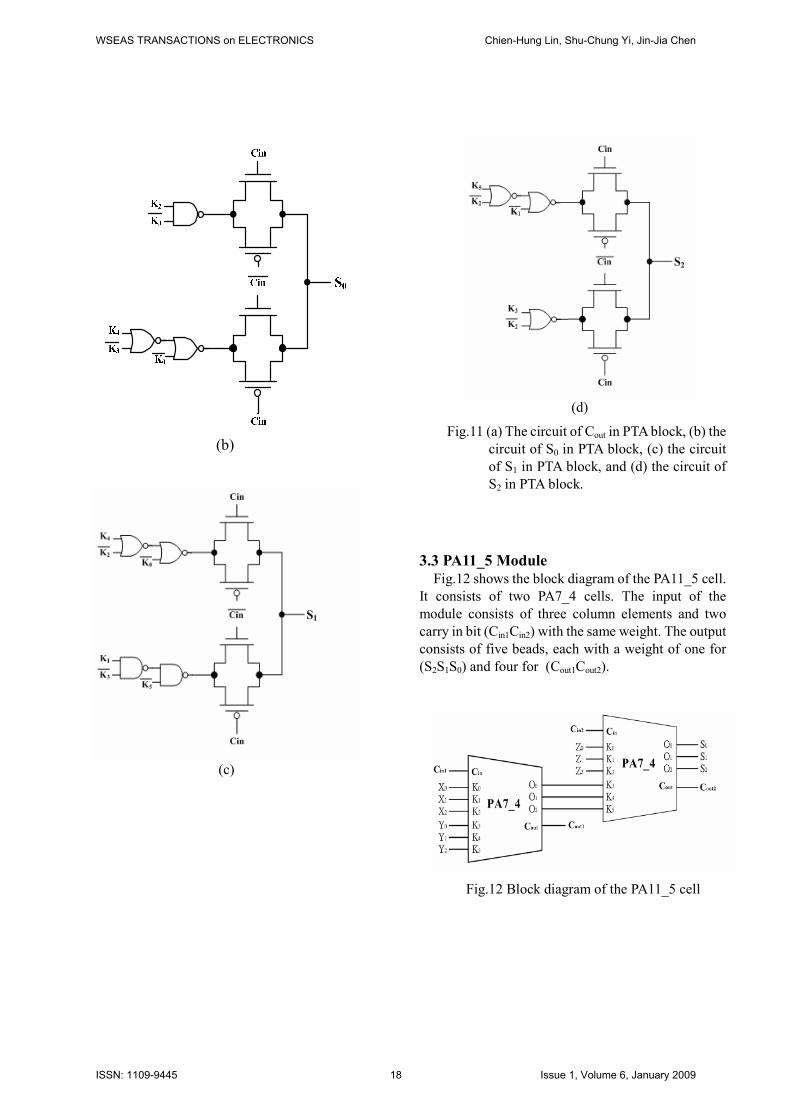
Fig.11 (a) The circuit of Cout in PTA block, (b) the
circuit of S0 in PTA block, (c) the circuit
of S1 in PTA block, and (d) the circuit of
S2 in PTA block.
3.3 PA11_5 Module
Fig.12 shows the block diagram of the PA11_5 cell.
It consists of two PA7_4 cells. The input of the
module consists of three column elements and two
carry in bit (Cin1Cin2) with the same weight. The output
consists of five beads, each with a weight of one for
(S2S1S0) and four for (Cout1Cout2).
Fig.12 Block diagram of the PA11_5 cell
WSEAS TRANSACTIONS on ELECTRONICS Chien-Hung Lin, Shu-Chung Yi, Jin-Jia Chen
ISSN: 1109-9445 18 Issue 1, Volume 6, January 2009

3.4 PA3_3 Module
PA3_3 transforms two beads Y1Y0 and the carry
bead Cin into the output (S2S1S0) weighted by one.
The truth table for PA3_3 is shown in Table 2. The
behavior of the PA3_3 module is modeled in the
equations (30) - (32), and the detailed circuits of
PA3_3 are depicted in Fig.13.
Table 2 the truth table of PA3_3
Inputs Outputs
Y1, Y0, Cin S2 S1 S0
0, 0, 0 0 0 0
0, 0, 1 0 0 1
0, 1, 0 0 0 1
0, 1, 1 0 1 1
1, 0, 0 * * *
1, 0, 1 * * *
1, 1, 0 0 1 1
1, 1, 1 1 1 0
inin CYCS 00 )1( += (30)
inin CYCYS 101 += (31)
inin CCYS )0(12 += (32)
(a)
(b)
(c)
Fig. 13 (a) The circuit of S0 in PA3_3 block, (b) the
circuit of S1 in PA3_3 block, and (c) the
circuit of S2 in PA3_3 block.
3.4 PAC7_4 Module
Fig.14 shows the block diagram of the PAC7_4
module. It consists of the PA7_4 cell and PA3_3 cell.
This module is composed of two column elements,
(Y1Y0) and (X2X1X0), and two carry bits (Cin1Cin2)
with the same weight. The output consists of four
beads, each with a weight of one for (S2S1S0) and four
for (Cout).
WSEAS TRANSACTIONS on ELECTRONICS Chien-Hung Lin, Shu-Chung Yi, Jin-Jia Chen
ISSN: 1109-9445 19 Issue 1, Volume 6, January 2009

Fig.14 Block diagram of the PAC7_4 cell
4 Simulations and Comparisons
In the previous sections we have designed a
multiplier using the methodology of the Chinese
abacus. The circuits of the prototype are simulated
using HSPICE and the 0.35µm and 0.18µm TSMC
CMOS technologies. For the sake of simplicity, all the
lengths and widths of the transistors were set to be the
smallest value allowed by each technology, and the
width size of PMOS transistors was 2.5 times of that
of NMOS transistors. CMOS inverters were used as
loads in each output in the simulations. The
simulation was performed at a frequency of 50 MHz,
with 0.35µm CMOS technology. All of the output and
input waves are shown in Fig.15. The power
consumption wave is also shown in Fig.16.
Fig.15 Simulation output and input waves of the 4-bit
Chinese abacus multiplier
Fig.16 Simulation power consumption of the 4-bit
Chinese abacus multiplier.
The simulation results are compared with those of
the Braun array multiplier, as listed in Table 3 and
Table 4.The delay is defined as the longest signal time
from input to output with all input patterns. The 4x4
abacus multiplier results a delay of 2.83ns and
1.432ns for 0.35µm and 0.18µm TSMC CMOS
technologies, respectively. These data are 19.7% and
10.6% less than those of the Braun array multiplier for
the same 0.35µm and 0.18µm technologies,
respectively. Also the delays of the 8-bit abacus
WSEAS TRANSACTIONS on ELECTRONICS Chien-Hung Lin, Shu-Chung Yi, Jin-Jia Chen
ISSN: 1109-9445 20 Issue 1, Volume 6, January 2009

multiplier are 14% and 7.5% less than those of the
Braun array multiplier with 0.35µm and 0.18µm
technologies, respectively.
The power consumption levels of various
multipliers using different methodologies is also
listed in Table 3 and Table 4.The average results of
the power consumption are different for all input
patterns. The simulation was performed at a
frequency of 50MHz. For the 4-bit abacus multiplier
power consumptions were 8.7 % and 18% less than
those of the Braun array multiplier with 0.35µm and
0.18µm technologies, respectively. The power
consumption levels of the 8-bit abacus multiplier were
11.9% and 22.3% less than those of the Braun array
multiplier with 0.35µm and 0.18µm technologies,
respectively. From these results, we conclude that the
abacus multiplier still has competitive with the Braun
array multiplier. The chip layout of the 4x4 abacus
multiplier is shown in Fig.17.
TABLE 3. Simulation results of the 4x4 array multiplier and abacus
multiplier
Tech.
[8]
Braun
Abacus
Reduction
% (compare
to Braun )
Delay 0.35 - 3.39 2.83 19.7%
(ns) 0.18 3.97 1.584 1.432 10.6%
Power 0.35 - 313 288 8.7%
(µw) 0.18 145.5 45.2 38.3 18%
P*D 0.35 - 1061 815 30%
(µw*n
s)
0.18 577.6 71.6 54.8 30%
TABLE 4. Simulation results of 8x8 array Multiplier and abacus
multiplier
Tech.
[10]
Braun
Abacus
Reduction %
(compare to
Braun )
Delay 0.35 - 7.69 6.75 14%
(ns) 0.18 6.98 3.60 3.35 7.5%
Power 0.35 - 1.52 1.36 11.9%
(mw) 0.18 0.188 0.216 0.179 22.3%
P*D 0.35 - 11.69 9.18 27%
(mw*ns) 0.18 1.312 0.778 0.599 29.8%
4 Conclusion
We propose a multiplier based on the Chinese
abacus algorithm that all the results are simulated by
0.18µm and 0.35µm TSMC CMOS technologies,
respectively. As can be concluded from the simulation
results, the delays level of the 8-bit abacus multiplier
are 14% and 7.5% less than those of Braun array
multiplier with 0.35µm and 0.18µm technologies,
respectively; furthermore, the power consumption of
the 8-bit abacus multiplier is about 11.9 % and 22.3%
less than those of the Braun array multiplier with
0.35µm and 0.18µm technologies. Obviously, this
proposed abacus multiplier can significantly reduce
the delay and the power consumption that it owns the
competitive ability with respect to conventional fast
multipliers.
Figure 17 Chip layout of the 4x4 abacus multiplier
using 0.35µm TSMC CMOS technology.
References:
[1] S. D. Pezaris, A 40-ns 17-bit by 17-bit array
multipliers, IEEE Transactions on Computers,
Vol. 20, April 1971, pp. 442-447.
[2] K.Z. Pekmestzi, Multiplexer-based array
multipliers, IEEE Transactions on Computers,
Vol. 48, No. 1, Jan. 1999, pp. 15-23.
[3] C. Wallace, A suggestion for a fast multiplier,
IEEE Transactions on Electronic Computers, Vol.
13, 1964, pp. 14-17.
[4] Franco Maloberti and Chen Gang, The Chinese
Abacus method: can we use it for digital
WSEAS TRANSACTIONS on ELECTRONICS Chien-Hung Lin, Shu-Chung Yi, Jin-Jia Chen
ISSN: 1109-9445 21 Issue 1, Volume 6, January 2009

arithmetic, Proceedings of the 8th Great Lakes
Symposium on VLSI, 19-21, Feb. 1998 pp. 192 –
195.
[5] Franco Maloberti and Chen Gang, Use of the
Chinese Abacus method for digital arithmetic
functions, Proceedings of the 1998 IEEE
International Symposium on Circuits and Systems,
Vol. 5, 31 May - 3 June 1998 pp. 213 – 216.
[6] Franco Maloberti and Chen Gang, Performing
Arithmetic Functions with the Chinese Abacus
Approach, IEEE Transaction on circuits and
systems-II: Analog and digital signal processing,
Vol. 46,No. 12, Dec. 1999, pp. 1512 – 1515.
[7] Shu-Chung Yi., Kun-Tse Lee., Jin-Jia Chen.,
Chien-Hung Lin., Chuen-Ching Wang., Chin-Fa
Hsieh and Chih-Yung Lu., The new architecture
of radix-4 Chinese abacus adder, IEEE
International Symposium on Multiple-Valued
Logic, 17-20 May. 2006, pp. 12-15.
[8] Vasefi, F., and Abid, Z, Low power n-bit adders
and multiplier using lowest-number-of-transistor
1-bit adders, Canadian Conference on Electrical
and Computer Engineering, May. 2005, pp.
1731 – 1734.
[9] Shu-Chung Yi, Zi-Yi Zhao, Chien-Hung Lin, Yu-Zhi Xie, Yen-Ju Chen, Yi-Jie Lin, The novel Chinese
abacus adder, IEEE International Symposium on VLSI
Design, Automation and Test (VLSI-DAT),
Ambassador Hotel, Hsinchu, Taiwan, April 25-27,
2007, pp. 270–273.
[10] Van, L.-D., and Chih-Chyau Yang,, Generalized
Low-Error Area-Efficient Fixed-Width
Multipliers, IEEE Transactions on Circuits and
Systems, Vol. 52, Aug. 2005, pp. 1608 – 1619.
WSEAS TRANSACTIONS on ELECTRONICS Chien-Hung Lin, Shu-Chung Yi, Jin-Jia Chen
ISSN: 1109-9445 22 Issue 1, Volume 6, January 2009