a multi-scale enriched model for the analysis of masonry panels · a dipartimento di ingegneria...
TRANSCRIPT

International Journal of Solids and Structures 49 (2012) 865–880
Contents lists available at SciVerse ScienceDirect
International Journal of Solids and Structures
journal homepage: www.elsevier .com/locate / i jsols t r
A multi-scale enriched model for the analysis of masonry panels
Daniela Addessi a,⇑, Elio Sacco b
a Dipartimento di Ingegneria Strutturale e Geotecnica, Università di Roma ‘‘Sapienza’’, Via Eudossiana 18, 00184 Roma, Italyb Dipartimento di Meccanica, Strutture, Ambiente e Territorio, Università di Cassino, Via G. Di Biasio 43, 03043 Cassino, Italy
a r t i c l e i n f o a b s t r a c t
Article history:Received 12 May 2011Received in revised form 11 October 2011Available online 29 December 2011
Keywords:Multi-scale modelMasonryNonlinear homogenizationDamage–frictionCosserat continuum
0020-7683/$ - see front matter � 2012 Elsevier Ltd. Adoi:10.1016/j.ijsolstr.2011.12.004
⇑ Corresponding author. Tel.: +39 0644585298; faxE-mail address: [email protected] (D. A
A multi-scale model for the structural analysis of the in-plane response of masonry panels, characterizedby periodic arrangement of bricks and mortar, is presented. The model is based on the use of two scales:at the macroscopic level the Cosserat micropolar continuum is adopted, while at the microscopic scalethe classical Cauchy medium is employed. A nonlinear constitutive law is introduced at the microscopiclevel, which includes damage, friction, crushing and unilateral contact effects for the mortar joints. Thenonlinear homogenization is performed employing the Transformation Field Analysis (TFA) technique,properly extended to the macroscopic Cosserat continuum. A numerical procedure is developed andimplemented in a Finite Element (FE) code in order to analyze some interesting structural problems. Inparticular, four numerical applications are presented: the first one analyzes the response of the masonryRepresentative Volume Element (RVE) subjected to a cyclic loading history; in the other three applica-tions, a comparison between the numerically evaluated response and the micromechanical or experi-mental one is performed for some masonry panels.
� 2012 Elsevier Ltd. All rights reserved.
1. Introduction
The masonry is a structural material obtained joining natural orartificial bricks by means of mortar layers. Thus, it is a heteroge-neous material; for this reason, in the last 20 years, several research-ers developed models based on the micromechanical analysis of themasonry, adopting homogenization techniques. In this framework,different constitutive masonry models have been proposed in theliterature; they have been obtained according to the assumptionsschematically reported below:
1. Arrangement of the masonry:(a) regular arrangement, i.e. masonry considered as a periodic
composite material;(b) quasi-periodic or irregular texture of the masonry.
2. Model for the brick:(a) rigid;(b) deformable with linear response;(c) interface or continuum material characterized by nonlinear
response.3. Model for the mortar:
(a) interface or continuum material characterized by linearresponse;
(b) interface or continuum material characterized by nonlinearresponse;
ll rights reserved.
: +39 064884852.ddessi).
4. Macroscopic model obtained by homogenization:(a) Cauchy continuum;(b) Cosserat or higher order continua.
Moreover, various homogenization techniques have been pro-posed and applied for masonry heterogeneous materials. Thus,selecting among the different possible mechanical assumptionsand adopting different homogenization techniques, many masonrymodels and numerical procedures have been obtained.
From a review of the available literature, it can be noted thatmost of the references deal with the in-plane analysis of periodicmasonry panels. In this framework, Cauchy models are recoveredapplying periodic homogenization techniques and considering theelastic behavior of both brick and mortar by Anthoine (1995) andLuciano and Sacco (1998). Nonlinear masonry models are proposed,for example, by Sacco (2009), assuming the elastic response of thebrick and a coupled damage–friction model for the mortar. Further-more, several models based on the nonlinear response of both theconstituents of the masonry, brick and mortar, are presented inthe literature. Among the others, Gambarotta and Lagomarsino(1997b) consider an equivalent stratified medium made up of mor-tar joints and brick units layers and adopt damage constitutive lawsboth for the bricks and the mortar joints. Massart et al. (2007) pro-pose an enhanced multi-scale model using nonlocal implicit gradi-ent isotropic damage models for both the constituents, describingthe damage preferential orientations and employing at the macro-scopic scale an embedded band model. Zucchini and Lourenco(2009) propose an improved micromechanical model for masonry
866 D. Addessi, E. Sacco / International Journal of Solids and Structures 49 (2012) 865–880
homogenization in the nonlinear domain, incorporating suitablychosen deformation mechanisms coupled with damage and plastic-ity models. Wei and Hao (2009) develop a continuum damagemodel for masonry accounting for the strain rate effect, using ahomogenization theory implemented in a numerical algorithm.
In the framework of the Cosserat continuum models, Masianiet al. (1995) and Masiani and Trovalusci (1996) study the case oftwo-dimensional periodic rigid block assemblies joined by elasticmortar, deducing the macroscopic characterization of the equiva-lent medium by equating the virtual stress power of the coarsemodel with the virtual power of the internal actions of the discretefine model. Salerno and de Felice (2009) investigate on the accu-racy of various identification schemes for Cauchy and Cosserat con-tinua, showing that in the case of non periodic deformation statesmicropolar continuum better reproduces the discrete solutions,due to its capability to take scale effects into account. Casolo(2006) considers isotropic linear elastic models both for the brickand the mortar and uses a computational approach to identifythe homogenized elastic tensor of the equivalent Cosserat medium.Sab and Pradel (2009) present the development of homogenizationprocedures for Cosserat materials with periodic micro-structure,critically discussing about other existing homogenization proce-dures. Nonlinear response of the mortar joints is assumed by Ad-dessi et al. (2010), using a cohesive-friction constitutive model.Moreover, nonlinear behavior for both brick and mortar is consid-ered by De Bellis and Addessi (2011). An in-plane multi-level strat-egy is proposed by Brasile et al. (2007a,b) for the static anddynamical multi-scale analysis of masonry walls.
Most of the existing models for masonry concern periodicmicrostructures. Cecchi and Sab (2009) analyze non-periodicmasonries, typical of historical buildings, by means of a perturba-tion approach, while Cavalagli et al. (2011) deal with the evalua-tion of the strength domain for non-periodic masonry using arandom media micromechanical approach.
Also the out-of-plane analysis of masonry panels is a veryimportant and interesting issue. In fact, recent earthquakes showthat the out-of-plane failure of masonry walls is responsible ofthe loss of human life. Mercatoris and Massart (2011) presents amulti-scale framework for the failure of periodic quasi-brittle thinplanar shells, using a shear-enhanced element with the Reissner-Mindlin description and employing it for the failure of out-of-planeloaded masonry walls.
With the aim of satisfactorily describing the structural behaviorof masonry panels, reproducing accurately both the global and lo-cal response, a reliable masonry model should account for the non-linear response of the constituents and the deformability of thebricks. In particular, because of the cohesive (quasi-brittle) re-sponse of the masonry material constituents, softening effects arisein the stress–strain relationship, which can induce localization ofdeformations and damage in structural analyses, when the classi-cal Cauchy continuum model is adopted. In order to overcome suchdrawbacks, nonlocal approaches or higher-order continuum mod-els can be adopted. Moreover, spurious localization can be miti-gated also introducing special tricks within the FE method. Tothis end, one simple and widely adopted approach to overcomethe localization problem is the fracture energy regularization (Ba-zant and Planas, 1998). More sophisticated methods consist in theenrichment of the kinematic description in the FE, considering forinstance the presence of strong discontinuities in the displacementfield (Linder and Armero, 2007). On the other hand, a homogeniza-tion method leading to a Cauchy continuum is unable to predictsize effects in the mechanical behavior of heterogeneous materials.Then, the adoption of a generalized continuum gives a natural wayto obtain an explicit dependence of the effective properties of com-posites or multiphase materials on the absolute size of the constit-uents with a continuum model and to account for size effects.
The Cosserat model can be considered as an effective approachboth from a mechanical point of view, mainly when the size of themicrostructure is relevant, and for computational reasons, since itallows to naturally regularize the problem in the case of predomi-nant shearing damaging mechanisms in the masonry panels.
In this paper a multi-scale approach for the analysis of the in-plane masonry response is presented, adopting a Cosserat modelat the macro-level and a classical Cauchy medium at the micro-structural level. The choice of using two different continuum mod-els is based on the following considerations. At the macro-scale, asremarked above, the adoption of the micropolar Cosserat model al-lows to account for the internal length of the material and to mit-igate or overcome localization problems. From a mechanical pointof view, the Cosserat rotation field can describe the rotation of thebricks composing the masonry texture, mainly when the mortarjoints are damaged. However, it can be emphasized that the settingof the Cosserat elastic moduli is not straightforward. Thus, thehomogenization procedure based on the micromechanical analysisof the RVE allows to rationally derive the components of the elasticCosserat matrix. On the other hand, at the micro-scale level theclassical Cauchy model can be considered absolutely satisfactory.Various examples of coupling two different continuum modelscan be found in literature. Forest and Sab (1998) use a Cosseratcontinuum at the macro-level and a Cauchy medium at the mi-cro-level, applying the homogenization procedure to a multi-layercomposite material. Kouznetsova et al. (2002) present a gradient-enhanced computational procedure that extends the classical com-putational homogenization technique to a full-gradient geometri-cally nonlinear approach. They adopt a higher-order continuumat the macroscopic level, while the microstructural constituentsare modeled as a classical Cauchy continuum. This may haveadvantages over the modeling of the microstructure by a general-ized continuum, since, for nonlinear material behavior, the formu-lation of constitutive equations and experimental procedures formaterial parameter identification are sufficiently developed andverified in the framework of classical continuum models. A sec-ond-order computational homogenization of heterogeneous mate-rials is proposed by Bacigalupo and Gambarotta (2011). Thecomputational procedure is derived assuming an appropriate rep-resentation of the micro-displacement field as the superposition ofa local macroscopic displacement field and an unknown micro-fluctuation field accounting for the effects of the heterogeneities.
In the present work regular arrangements of bricks and mortarare considered, assuming a linear elastic behavior for the brick anda damage-plastic constitutive law, which accounts for the internalfriction effect, for the mortar joints. The proposed constitutivemodel takes into account also the crushing plasticity mechanisms.Furthermore, a degrading exponential law is adopted for the fric-tion parameter in order to reproduce the experimental results. Ahomogenization technique is developed to identify the equivalentCosserat macroscopic continuum model. In particular, in order toaccount for the nonlinear behavior of the mortar joints, the Trans-formation Field Analysis (TFA) technique, originally presented byDvorak (1992) and recently proposed by Addessi et al. (2010) forthe micromechanical analysis of the masonry RVE, is hereinadopted. A multi-scale computational strategy is developed andimplemented in the Finite Element (FE) code FEAP (Taylor, 2011).Numerical applications are finally presented to investigate on theability of the proposed model to reproduce the mechanical re-sponse of masonry panels and to assess the effectiveness androbustness of the developed numerical procedure. To this end,comparisons with micromechanical and experimental tests areperformed, investigating both on the global response and on the lo-cal mechanisms. In Section 2 the two boundary value problems(BVP) formulated at the macro- and micro-scale are introduced;in Section 3, the description of the TFA-based nonlinear homogeni-
D. Addessi, E. Sacco / International Journal of Solids and Structures 49 (2012) 865–880 867
zation procedure is given; in Section 4, the numerical procedureand the developed solution algorithm is described; lastly, in Sec-tion 5 some numerical examples are reported. Finally, commentsand remarks on the developed model and the implemented com-putational procedure are given.
2. Multi-scale model for periodic masonry
A two-scale model for the analysis of 2D masonry structures isintroduced, based on the adoption of the Cosserat continuum at thestructural macro-level and the classical Cauchy medium at the mi-cro-level. The proposed multi-scale approach is based on the completeseparation of the two scales and a homogenization procedure is em-ployed to rationally derive the constitutive relationship at each macro-scopic integration point. To this end, the equilibrium equations aresatisfied with zero body force at the micro-scale, together with thecompatibility and constitutive laws of the single constituents. At thestructural scale, equilibrium and compatibility are satisfied, whilethe constitutive relations are derived by means of the homogenizationtechnique from the micro-scale. This multi-scale approach, which canbe considered the most classical and popular micro–macro procedure,is defined as ‘uncoupled multi-scale mathematical model’ by Fish andShek (2000). As remarked by Fish and Shek (2000), it can be appliedwith satisfactory approximation for large scale problems, i.e. whenthe size of the structure is much greater than the size of the micro-structure, otherwise coupled models have to be used.
As widely shown in literature, the enriched micropolar Cosseratmodel at the macro-level allows to account for the microstructuralinteraction effects, related to the size and shape of the constitu-ents, on the structural response. On the other hand, most of thedamage-plastic constitutive models proposed in literature for ma-sonry constituents are formulated and identified in the frameworkof the classical Cauchy continuum, thus suggesting the adoption ofthe Cauchy model at the micro-level.
In the spirit of the multi-scale procedure, two BVPs are formu-lated at the macro- and micro-level, respectively, together with aproperly conceived kinematic map connecting the two levels andgetting information across them. In the following, the equationsgoverning the two BVPs and the adopted nonlinear homogeniza-tion procedure are illustrated. Small strain and displacementassumptions hold.
2.1. Macro-level BVP
At the macro-level, where the Cosserat continuum model is em-ployed, the displacement vector U = {U1 U2 U}T contains threeindependent kinematic fields, representing the translations U1
and U2 and the rotation U, respectively, at each point X =(X1,X2)T of the body volume X. The compatibility equations, relat-ing the deformation components to the displacement fields, areintroduced in compact form as:
E ¼ DU in X ð1Þ
whose expanded form is:
E1
E2
C12
H
K1
K2
8>>>>>>>><>>>>>>>>:
9>>>>>>>>=>>>>>>>>;¼
@@X1
0 0
0 @@X2
0@@X2
@@X1
0
� @@X2
@@X1
�2
0 0 @@X1
0 0 @@X2
266666666664
377777777775U1
U2
U
8><>:9>=>; ð2Þ
where E is the strain vector and D the compatibility operator. Thefirst three components of E are the in-plane Cauchy extensional
and symmetric shear strains, H = E12 � E21 = 2(W �U) is the rota-tional deformation, representing two times the difference betweenthe rigid rotation W and the Cosserat rotation field U, being:
W ¼ 12
@U2
@X1� @U1
@X2
� �ð3Þ
and K1 and K2 are the curvatures.Accordingly, the stress vector R is expressed as:
R ¼ R1 R2 R12 Z M1 M2f gT ð4Þ
where R1 and R2 are the normal stresses, R12 is the symmetricshear stress, Z is the stress component associated to the rotationaldeformation H and M1 and M2 are the couples. The equilibriumequations result as:
DTRþ B ¼ 0 in X ð5Þ
where the vector B is formed by two components of body forces,namely B1 and B2, and one component of body couple C.
The displacement and traction boundary conditions are definedas follows:
U ¼ �U on @XU ; NR ¼ T on @XT ð6Þ
where �U is the displacement vector prescribed on the boundaryportion @XU, N is the matrix containing the unit vectors normal tothe traction boundary contour @XT and T is the vector of the exter-nal tractions.
A homogenization procedure is applied in order to derive theconstitutive response in each macroscopic material point by meansof the analysis of the corresponding RVE. In particular, for each RVEa BVP is solved, whose formulation is described in the followingsection, and the stress field calculated at the micro-level is homog-enized to obtain the macroscopic stress components by applyingthe generalized Hill–Mandel principle. Thus, the macroscopic elas-tic constitutive tensor C, obtained by applying the homogenizationtechnique on a RVE characterized by an orthotropic texture of themasonry, is expressed in the following form (Trovalusci and Masi-ani, 1999):
C ¼
C11 C12 0 0 0 0C21 C22 0 0 0 00 0 C33 C34 0 00 0 C43 C44 0 00 0 0 0 D11 00 0 0 0 0 D22
2666666664
3777777775ð7Þ
where the first 3 � 3 sub-matrix can be recognized as the standardin-plane elastic constitutive operator for the Cauchy continuumwith C12 = C21, C34 = C43 and C44 governing the skew-symmetricshear behavior, influenced by the shape of the RVE; D11 and D22
govern the flexural behavior affected by the absolute size of theRVE. It has to be noted that, when the damaging process startsand evolves, the RVE response may become anisotropic and, as aconsequence, the tangent constitutive tensor C is not characterizedby the orthotropic structure reported in (7) anymore. Nevertheless,the adopted homogenization procedure, described in the following,makes use of the elastic orthotropic constitutive tensor (7).
2.2. Micro-level BVP
In the following the equations governing compatibility, equilib-rium and constitutive behavior of the masonry RVE are introducedin the 2D framework. The analysis is limited to the case of periodicmasonry made of regular textures of bricks and mortar joints.
The displacement vector u = {u1,u2}T at each point x = {x1,x2}T ofthe RVE occupying the volume x at a given loading step is intro-
868 D. Addessi, E. Sacco / International Journal of Solids and Structures 49 (2012) 865–880
duced in a representation form as the superposition of a prescribedfield �u, defined as function the macroscopic deformation E, and anunknown periodic fluctuation ~u, satisfying proper periodicity con-ditions on the RVE boundary (Suquet, 1987; Luciano and Sacco,1998), namely:
u ¼ �uðxÞ þ ~uðxÞ in x ð8Þ
with:
~u periodic on @x ð9Þ
The compatibility equations are expressed in compact form as:
e ¼ du in x ð10Þ
where d is the compatibility operator and e the strain vector, whichaccordingly to Eq. (8) may be expressed as:
e ¼ �eðxÞ þ ~eðxÞ ð11Þ
being �e and ~e the strain fields compatible with �u and ~u, respectively.The expanded form of Eq. (10) is:
e1
e2
c12
8><>:9>=>; ¼
@@x1
0
0 @@x2
@@x2
@@x1
26643775 u1
u2
� �ð12Þ
Considering zero body forces acting on the RVE, the equilibriumequations result as:
dTr ¼ 0 in x ð13Þ
where the vector r, representing a self-equilibrated stress field, col-lects the stress components as:
r ¼ r1 r2 s12f gT ð14Þ
and satisfies the following boundary conditions:
nr anti-periodic on @x ð15Þ
where n denotes the matrix of the outward unit vectors normal to@x.
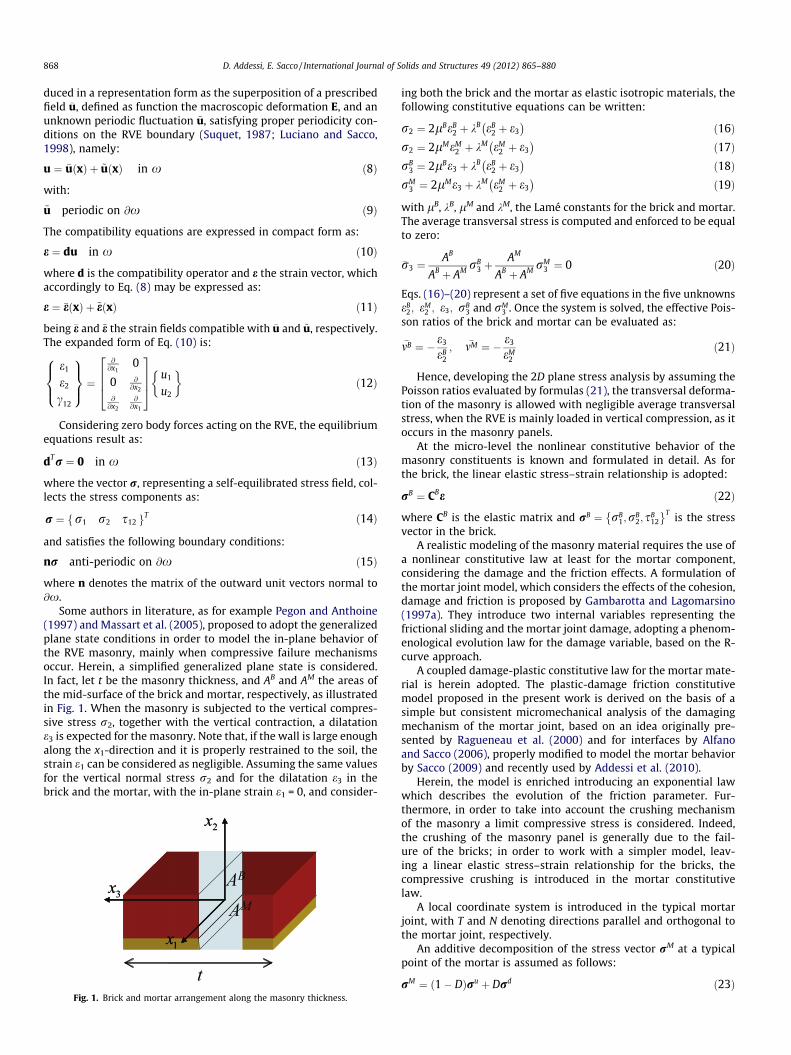
Some authors in literature, as for example Pegon and Anthoine(1997) and Massart et al. (2005), proposed to adopt the generalizedplane state conditions in order to model the in-plane behavior ofthe RVE masonry, mainly when compressive failure mechanismsoccur. Herein, a simplified generalized plane state is considered.In fact, let t be the masonry thickness, and AB and AM the areas ofthe mid-surface of the brick and mortar, respectively, as illustratedin Fig. 1. When the masonry is subjected to the vertical compres-sive stress r2, together with the vertical contraction, a dilatatione3 is expected for the masonry. Note that, if the wall is large enoughalong the x1-direction and it is properly restrained to the soil, thestrain e1 can be considered as negligible. Assuming the same valuesfor the vertical normal stress r2 and for the dilatation e3 in thebrick and the mortar, with the in-plane strain e1 = 0, and consider-
Fig. 1. Brick and mortar arrangement along the masonry thickness.
ing both the brick and the mortar as elastic isotropic materials, thefollowing constitutive equations can be written:
r2 ¼ 2lBeB2 þ kB eB
2 þ e3� �
ð16Þr2 ¼ 2lMeM
2 þ kM eM2 þ e3
� �ð17Þ
rB3 ¼ 2lBe3 þ kB eB
2 þ e3� �
ð18ÞrM
3 ¼ 2lMe3 þ kM eM2 þ e3
� �ð19Þ
with lB, kB, lM and kM, the Lamé constants for the brick and mortar.The average transversal stress is computed and enforced to be equalto zero:
�r3 ¼AB
AB þ AM rB3 þ
AM
AB þ AM rM3 ¼ 0 ð20Þ
Eqs. (16)–(20) represent a set of five equations in the five unknownseB
2; eM2 ; e3; rB
3 and rM3 . Once the system is solved, the effective Pois-
son ratios of the brick and mortar can be evaluated as:
�mB ¼ � e3
eB2
; �mM ¼ � e3
eM2
ð21Þ
Hence, developing the 2D plane stress analysis by assuming thePoisson ratios evaluated by formulas (21), the transversal deforma-tion of the masonry is allowed with negligible average transversalstress, when the RVE is mainly loaded in vertical compression, as itoccurs in the masonry panels.
At the micro-level the nonlinear constitutive behavior of themasonry constituents is known and formulated in detail. As forthe brick, the linear elastic stress–strain relationship is adopted:
rB ¼ CBe ð22Þ
where CB is the elastic matrix and rB ¼ rB1;rB
2; sB12
� T is the stressvector in the brick.
A realistic modeling of the masonry material requires the use ofa nonlinear constitutive law at least for the mortar component,considering the damage and the friction effects. A formulation ofthe mortar joint model, which considers the effects of the cohesion,damage and friction is proposed by Gambarotta and Lagomarsino(1997a). They introduce two internal variables representing thefrictional sliding and the mortar joint damage, adopting a phenom-enological evolution law for the damage variable, based on the R-curve approach.
A coupled damage-plastic constitutive law for the mortar mate-rial is herein adopted. The plastic-damage friction constitutivemodel proposed in the present work is derived on the basis of asimple but consistent micromechanical analysis of the damagingmechanism of the mortar joint, based on an idea originally pre-sented by Ragueneau et al. (2000) and for interfaces by Alfanoand Sacco (2006), properly modified to model the mortar behaviorby Sacco (2009) and recently used by Addessi et al. (2010).
Herein, the model is enriched introducing an exponential lawwhich describes the evolution of the friction parameter. Fur-thermore, in order to take into account the crushing mechanismof the masonry a limit compressive stress is considered. Indeed,the crushing of the masonry panel is generally due to the fail-ure of the bricks; in order to work with a simpler model, leav-ing a linear elastic stress–strain relationship for the bricks, thecompressive crushing is introduced in the mortar constitutivelaw.
A local coordinate system is introduced in the typical mortarjoint, with T and N denoting directions parallel and orthogonal tothe mortar joint, respectively.
An additive decomposition of the stress vector rM at a typicalpoint of the mortar is assumed as follows:
rM ¼ ð1� DÞru þ Drd ð23Þ
s
h
bx
2 a1
2 a2
s
h
bx
x2
2 a1
2 a21
2
1
3
4
5 6
7 8
Fig. 2. Selected RVE: running bond texture.
D. Addessi, E. Sacco / International Journal of Solids and Structures 49 (2012) 865–880 869
where D is the scalar damage parameter, measuring the ratio be-tween the damaged part of the representative mortar area andthe total representative area. The two stress vectors ru and rd arerelated to the strain vector in the mortar, e, by the constitutiveequations:
ru ¼ CMðe� pÞ; rd ¼ CMðe� ep � pÞ ð24Þ
where
CM ¼CM
TT CMNT 0
CMNT CM
NN 0
0 0 GM
264375 ð25Þ
represents the elasticity matrix of the mortar, ep is the vector of thestrain accounting for the possible unilateral opening effect and forthe friction sliding, while p is the plastic strain due to the crushing.
Taking into account the constitutive Eqs. (24), Eq. (23) becomes:
rM ¼ CMðe� pÞ ð26Þ
where p is the vector collecting all the inelastic strains, conve-niently written in the form:
p ¼pT
pN
pNT
8><>:9>=>; ¼
0pN
0
8><>:9>=>;þ D
hðeN � pNÞeT
hðeN � pNÞðeN � pNÞcp
NT
8><>:9>=>; ð27Þ
accounting for the crushing, pN, the damage, D, the unilateral con-tact by means of the component h(eN � pN)(eN � pN) and the slipby means of the component cp
NT ; hðeN � pNÞ is the Heaviside func-tion, which assumes the following values: h(eN � pN) = 0 if (eN -� pN) 6 0 and h(eN � pN) = 1 if (eN � pN) > 0. Because of thesimplified form of the inelastic strain (27), the constitutive law(24) is able to provide zero normal stress in transversal direction,rd
N ¼ 0, as well as in longitudinal direction, rdT ¼ 0, when opening
of the mortar joint occurs.The crushing and the friction effects are modeled as classical
plasticity problems. The evolution law of the crushing inelasticstrain component pN is stated as:
_pN ¼ � _kp ð28Þ
and it is ruled by the Kuhn–Tucker conditions, being kp the inelasticmultiplier:
_kp P 0; wðrÞ 6 0; _kpwðrÞ ¼ 0 ð29Þ
The yield function is assumed as:
wðrÞ ¼ �ðrN þ ry þ anÞ ð30Þ
where ry is the compressive yield threshold, a 6 0 is the softeningparameter and n is the total plastic strain evaluated as:
n ¼Z t
0j _pNjds ð31Þ
As concerning the friction mechanism, the evolution of theinelastic slip strain component cp
NT is governed by the Coulombyield function:
uðrdÞ ¼ lðfÞrdN þ jsd
NT j ð32Þ
where l is the friction parameter evolving according to the follow-ing exponential law:
lðfÞ ¼ ðlf � liÞð1� e�dfÞ þ li ð33Þ
being li and lf the initial and final friction values, respectively, d theexponential rate parameter and f the total plastic slip strain,defined as:
f ¼Z t
0j _cp
NT jds ð34Þ
A non-associated flow rule is considered as:
_cpNT ¼ _k
sdNT
jsdNT j
ð35Þ
with the following loading–unloading Kuhn–Tucker conditions:
_k P 0 uðrdÞ 6 0; _k uðrdÞ ¼ 0 ð36Þ
where k is the inelastic multiplier.A model which accounts for the coupling of mode I and mode II
of fracture is considered for the evolution of the damage parameterD. The two quantities gN and gNT, which depend on the first crack-ing strains eN,0 and cNT,0, on the peak values of the stresses rN,0 andsNT,0 and on the fracture energies GcI and GcII, respectively, areintroduced in the form:
gN ¼eN;0rN;0
2GcI; gNT ¼
cNT;0sNT;0
2GcIIð37Þ
The equivalent strain measures YN and YNT are defined as:
YN ¼ ðheN � pNiÞ2; YNT ¼ ðcNTÞ
2 ð38Þ
where the bracket operator h�i gives the positive part of the quantity�. Then, the strain ratios are determined as:
g ¼ 1a2 YNgN þ YNTgNTð Þ; b ¼
ffiffiffiffiffiffiffiffiffiffiffiffiffiffiffiffiffiffiffiffiffiffiffiYN
e2N;0
þ YNT
c2NT;0
s; a
¼ffiffiffiffiffiffiffiffiffiffiffiffiffiffiffiffiffiffiffiffiYN þ YNT
pð39Þ
Finally, the damage is evaluated according to the following law:
D ¼ maxhistory
fminf1; �Dgg with �D ¼ b� 1ð1� gÞb ð40Þ
3. Homogenization technique
The constitutive response in each macroscopic point of theequivalent Cosserat continuum is derived by adopting the compat-ible nonlinear homogenization procedure presented in Addessiet al. (2010), based on the TFA technique. In the following, the mainsteps of such methodology are illustrated.
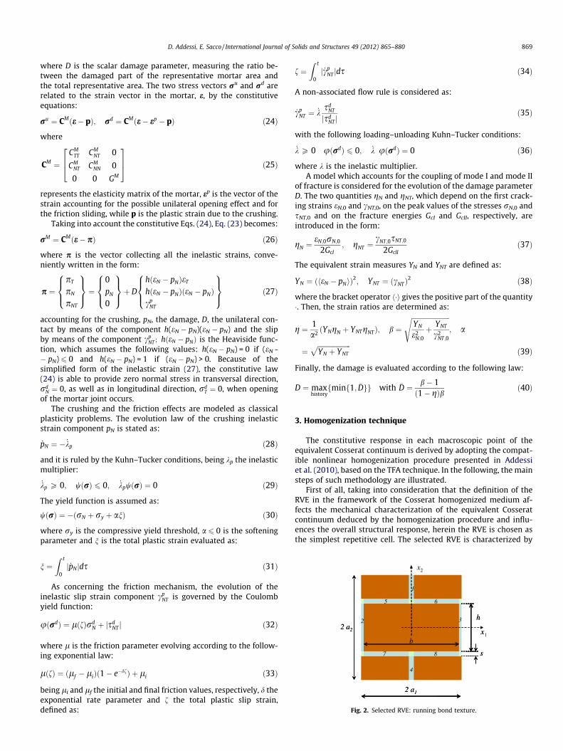
First of all, taking into consideration that the definition of theRVE in the framework of the Cosserat homogenized medium af-fects the mechanical characterization of the equivalent Cosseratcontinuum deduced by the homogenization procedure and influ-ences the overall structural response, herein the RVE is chosen asthe simplest repetitive cell. The selected RVE is characterized by

870 D. Addessi, E. Sacco / International Journal of Solids and Structures 49 (2012) 865–880
rectangular shape with dimensions 2a1 and 2a2, parallel to thecoordinate axes x1 and x2, as shown in Fig. 2. The RVE accountsfor all the geometrical and constitutive properties of the masonrycomponents; in Fig. 2, the mortar thickness is denoted by s andthe brick sizes by b and h.
3.1. Kinematic map
The first step of the compatible homogenization procedure is toestablish a kinematic map linking the macro- and micro-level.Herein, following the methodology proposed by Forest and Sab(1998), third order polynomial expansions are assumed for the as-signed part of the microscopic displacement �uðxÞ, which allows totake into account all the macroscopic Cosserat deformation com-ponents. In the case of a rectangular cell, the following form ofthe assigned displacement �u is adopted in compact notation:
�u ¼ AðxÞE ð41Þ
where
A ¼x1 0 1
2 x2 �aðx32 � 3q2x2
1x2Þ �x1x2 � 12 x2
2
0 x212 x1 �q2aðq2x3
1 � 3x1x22Þ 1
2 x21 x1x2
" #ð42Þ
with
a ¼ 54
a21 þ a2
2
a41
; q ¼ a2
a1ð43Þ
In order to activate the Cauchy deformation modes independentlyfrom the Cosserat ones, in Eq. (41) the fourth component of theCosserat strain vector E is redefined as:
bH ¼ Hþ 12
q2 � 1q2 þ 1
C12 ð44Þ
The stress variable conjugated to bH is denoted with bZ .The strain vector at the micro-level (Eq. (11)) can now be ex-
pressed as:
e ¼ BðxÞEþ ~eðxÞ ð45Þ
where ~eðxÞ is the periodic strain, satisfying null average condition inx, and:
B ¼1 0 0 6aq2x1x2 �x2 00 1 0 6aq2x1x2 0 x1
0 0 1 3aðq2 � 1Þ x22 � q2x2
1
� �0 0
264375 ð46Þ
The in-plane periodicity and continuity conditions (9) lead to thefollowing boundary conditions:
~uða1; x2Þ ¼ ~uð�a1; x2Þ 8x2 2 ½�a2; a2�~uðx1; a2Þ ¼ ~uðx1;�a2Þ 8x1 2 ½�a1; a1�
ð47Þ
3.2. Nonlinear homogenization
The masonry RVE is subjected to the macroscopic Cosseratstrain E applied to the whole RVE and to the inelastic strain pi, withi = 1, . . . ,m, applied to each of the m mortar joints.
The micromechanical BVPs on the RVE, subjected to the pre-scribed value of the six components of E and to the three compo-nents of the inelastic strains pi in the m mortar joints, have to besolved. The micromechanical strain field, resulting after solvingthe BVP on the RVE subjected to E, can be written in the followingrepresentation form:
e ¼ ReðxÞE ð48Þ
where the localization matrix Re(x) is introduced. Consequently, theaverage strain in the brick and in each mortar joint Mi results as:
�eB ¼ �RBe E; �eMi ¼ �RMi
e E ð49Þ
where �RBe and �RMi
e denote the average localization matrices in thebrick volume and in the mortar joint volume, respectively.
The homogenized Cosserat stress in the whole RVE volume x isobtained by applying the generalized Hill–Mandel principle,resulting:
Re ¼ CE ð50Þ
where the overall elastic constitutive matrix is defined as:
C ¼ 1x
ZB
RTe CB edxþ
Xm
j¼1
ZMj
RTe CMj
edx
" #ð51Þ
Moreover, the average stress in the mortar joint Mi may be evalu-ated as �rMi
e ¼ CM�eMi ¼ CM �RMi
e E, as well as in the brick�rB
e ¼ CB�eB ¼ CB �RBe E.
Similarly, after solving the micromechanical problem of the RVEsubjected to an inelastic strain pi prescribed in the mortar joint Mi,the resulting local strain field is expressed in the form:
pi ¼ Rpi ðxÞpi ð52Þ
being Rpi ðxÞ the associated localization matrix. Note that the localstrain field pi is characterized by null average. The elastic strain inthe typical mortar joint Mj results as:
gi;Mj ¼ pi;Mj � dijpi ¼ RMj
pi � dijI� �
pi ðno sumÞ ð53Þ
where pi;Mjand RMj
pi are the restriction to the mortar Mj of the fieldspi and Rpi , respectively. The elastic strain in the brick coincides withthe total strain:
gi;B ¼ pi;B ¼ RBpipi ð54Þ
with evident meaning of the symbols. The corresponding overallCosserat stress can be obtained again by applying the generalizedHill–Mandel principle in the form:
Rpi ¼1x
ZB
RBpi
� �TCB gi;B dxþ
Xm
j¼1
ZMj
RMj
pi
� �TCMj
gi;Mjdx
" #
¼ 1x
ZB
RBpi
� �TCB RB
pi dxþXm
j¼1
ZMj
RMj
pi
� �TCMj
RMj
pi � dijI� �
dx
" #pi
ð55Þ
Aiming to express the macroscopic constitutive law in the form:
R ¼ CðE� PÞ ¼ CEe ð56Þ
where Ee = E � P is the overall elastic strain, the RVE is subjected tothe overall elastic strain Ee and to the inelastic strains pi,i = 1,2, . . . ,m, and superposition of the effects is heuristically per-formed. In fact, it is possible to compute the overall stress as:
R ¼ Re þXm
i¼1
Rpi ¼ CEþXm
i¼1
Rpi ð57Þ
so that the inelastic strain P can be defined as:
P ¼ �C�1Xm
i¼1
Rpi ð58Þ
Moreover, the total average strain in the m mortar joints is deter-mined as:
�eMj ¼ �RMj
e Eþ �RMj
pi pi ð59Þ
and the average stresses in the m mortar joints and in the brick aregiven by:
D. Addessi, E. Sacco / International Journal of Solids and Structures 49 (2012) 865–880 871
�rMj ¼ CM �eMj þ �g1;Mj þ � � � þ �gm;Mj� �
¼ CM �eMj � pj� �
�rB ¼ CB �eB þ �g1;B þ � � � þ �gm;B� �
¼ CB�eBð60Þ
Herein, it is assumed that:
� the inelastic strain is constant in each mortar joint;� the nonlinear behavior of the RVE depends on the average stres-
ses and strains evaluated in each of the m mortar joints.
4. Computational procedure
The FE method is used to solve the BVPs at the macro- and mi-cro-level. At the macro-level a 2D 4-node quadrilateral FE is imple-mented to discretize the Cosserat medium, with three degrees offreedom at each node, two translational and one rotational. In-stead, a standard Cauchy 4-node quadrilateral FE is adopted tomodel the RVE level with two translational degrees of freedom ateach node. A step-by-step solution technique based on the classicalbackward-Euler algorithm (Simo and Hughes, 1998) is adopted forthe integration of the governing equations, using a constant timestep Dt = tn+1 � tn. The nonlinear problem in each time step issolved by means of the Newton–Raphson technique.
The proposed nonlinear homogenization procedure initially re-quires the evaluation of the overall constitutive matrix C and of thelocalization matrices �RMj
e and �RMj
pi . They are computed by solving
Table 1Damage-plastic solution procedure in the mortar joint Mj
Iteration ‘k + 1’
Crushing evaluation– Prediction phase– Trial yield function
wkþ1;tr ¼ �ðrkþ1;trN þ ry þ ankþ1;trÞ
– Check plasticity
If wkþ1;tr < 0) Dkkþ1p ¼ 0, else
– Correction phase
Dkkþ1p ¼ wkþ1;tr
CMTT�a
with
Dkkþ1p P 0 wkþ1
6 0; Dkkþ1p wkþ1 ¼ 0
Dpkþ1N ¼ �Dkkþ1
p
nkþ1 ¼ nn þ jDpkþ1N j
Damage evaluation– Equivalent strain measures
YkN ¼ < ek
N � pkþ1N >
� �2; Yk
NT ¼ ckNT
� �2(Eq. (38))
– Strain ratiosgk, bk (Eq. (39))– DamageDk+1 (Eq. (40))
Unilateral effect evaluation
If ekN � pkþ1
N
� �6 0 then hk+1 = 0 else hk+1 = 1
If Dk+1 > 0
Friction plasticity evaluation– Prediction phase
pikþ1;tr ¼ pin ði ¼ 1; . . . ;mÞ
fk+1,tr = fn
– Trial yield function
ukþ1;tr ¼ lðfkþ1;trÞrdkþ1;tr
N þ sdkþ1;tr
NT
– Check plasticity
If ukþ1;tr < 0 ) Dcp;kþ1NT ¼ 0, else
– Correction phase
Dkkþ1 ¼ 1GM ukþ1;tr with
Dkk+1 P 0 uk+16 0, Dkk+1uk+1 = 0
Dcp;kþ1NT ¼ Dk
sdkþ1;trNT
sdkþ1;trNT
fkþ1 ¼ fn þ jDcp;kþ1
NT jlk+1 (Eq. (33))
6 + 3m FE linear elastic micromechanical problems at the RVElevel.
After that, the multi-scale solution procedure starts and goes onas described in the following, denoting with the subscript ‘n’ thevariables evaluated at the previous time step tn and using no sub-script to indicate the corresponding current quantities, i.e. com-puted at the step tn+1. Moreover, D denotes the increment of thevariable in the time step Dt.
In the spirit of the displacement-based FE method, at the cur-rent Newton–Raphson iteration the increment of the nodal dis-placements at the macro-level discretization is evaluated. Then,the macroscopic Cosserat strain vector increment DE is computedat each Gauss integration point and the strain vector E is updated.At this stage, the damage and plasticity evolution problem on theRVE subjected to the macroscopic Cosserat total strain E is solved,by adopting a return-mapping algorithm in order to evaluate theoverall Cosserat stress R. To this end, the strain E and the inelasticstrains pj (j = 1,2, . . . ,m), related to the crushing, damage and to theunilateral contact-friction effects occurring in the mortar joints,have to be calculated.
It is worthwhile noting that, as it is clear from Eq. (59), the aver-age strain �eMj
in the mortar joint Mj depends on the overall strain Eand on all the m inelastic strains pi (i = 1,2, . . . ,m). Consequently,the nonlinear evolution problems in the m mortar joints resultall coupled, giving rise to a complex nonlinear problem. Then, byexploiting the splitting procedure, the iterative procedure de-scribed below is employed, solving a set of m uncoupled evolution-ary problems, one for each mortar joint, considering as frozen thecrushing, damage and friction evolution into the others m � 1.
At the previous iteration k, the macroscopic Cosserat elasticstrain Ee is evaluated on the basis of the total strain E and of themacroscopic strain P associated to all the inelastic strains pi in
-0.8
-0.4
0.0
0.4
0.8
[MPa
]
Σ12
Γ12
-0.02 -0.01 0 0.01 0.02
-0.0012 -0.0008 -0.0004 0E2
-1.2
-0.8
-0.4
0.0
Σ 2 [M
Pa]
(a)
(b)
0
1
2
3
4
5
6
0-1
2-3
4-5
6
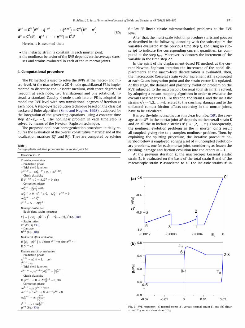
Fig. 3. RVE response: (a) normal stress R2 versus normal strain E2 and (b) shearstress R12 versus shear strain C12.
872 D. Addessi, E. Sacco / International Journal of Solids and Structures 49 (2012) 865–880
the mortar joints. Then, the total and elastic average strains in themortar joints, �eMj
and �gi;Mj, are computed.
At the current iteration and for all the mortar joints Mj, thecrushing plastic strains are evaluated by means of a prediction-cor-rection technique on the basis of the �eMj
evaluated at the previousiteration. Then, after updating the elastic normal strain in eachmortar on the basis of the current crushing plastic strains, thedamage associated variables YN and YNT together with the strain ra-tios g and b are computed and the damage variable is updated.Then, the unilateral contact problem is solved, by evaluating theHeaviside function h(eN � pN). Finally, if damage is active in themortar joint Mj, the friction problem is solved adopting a predic-tion–correction technique. A trial prediction of the inelastic strainspi is computed by assuming them equal to the ones evaluated atthe previous time step tn. The normal and trial shear stresses arethen evaluated, on the basis of which the trial yield function u iscalculated. The correction phase is performed if u > 0. Once thedamage, the unilateral contact and the friction problems are solvedin all the mortar joint Mj, the values of the inelastic strain vectors pj
are updated, then the new values of the total average strains �eMjare
determined. Thus, a further iteration is performed where compres-sive plasticity, damage, unilateral contact and friction problemshave to be solved again in all the mortar joints, until a convergencetest is satisfied. The scheme of the described solution algorithm isreported in Table 1, where the apex ‘Mj’ is omitted for easiernotation.
Writing Eq. (59) in residual form, the residual strain can be eval-uated in each mortar joint as:
qMj ;kþ1 ¼ �RMj
e EþXm
i¼1
�RMj
pi pi;kþ1 � �eMj ;kþ1 ð61Þ
(a)
(b)
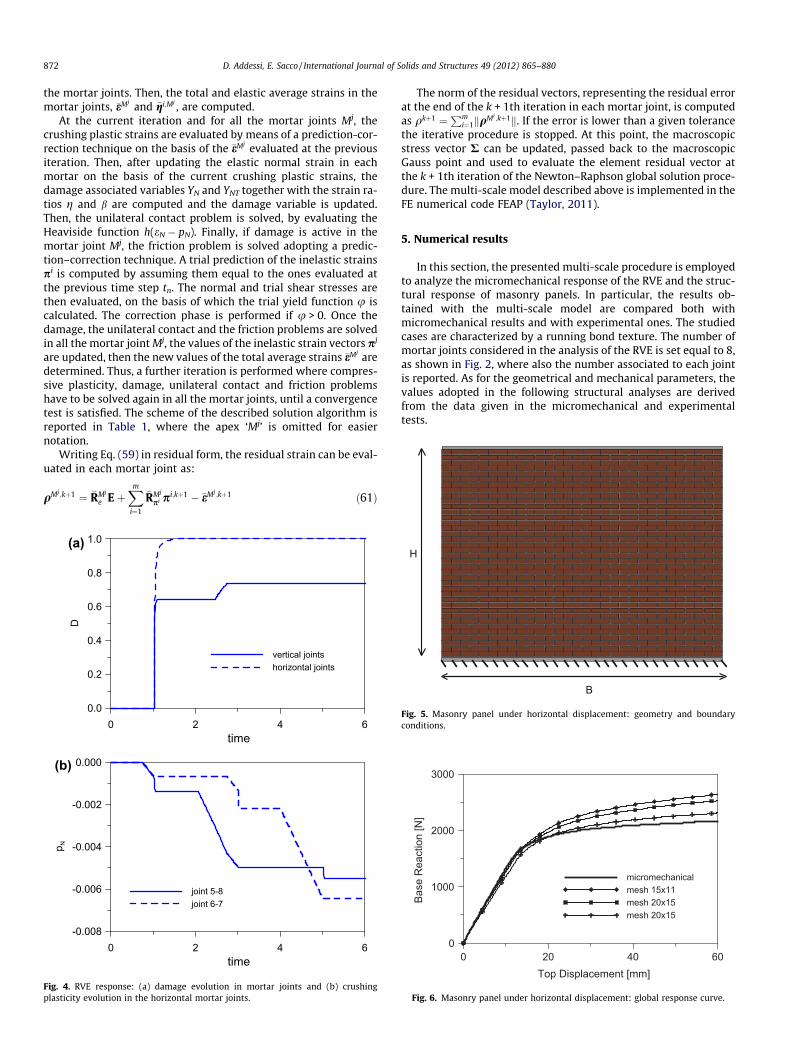
0 2 4 6time
0.0
0.2
0.4
0.6
0.8
1.0
D
vertical jointshorizontal joints
0 2 4 6time
-0.008
-0.006
-0.004
-0.002
0.000
p N
joint 5-8joint 6-7
Fig. 4. RVE response: (a) damage evolution in mortar joints and (b) crushingplasticity evolution in the horizontal mortar joints.
The norm of the residual vectors, representing the residual errorat the end of the k + 1th iteration in each mortar joint, is computedas qkþ1 ¼
Pmi¼1kqMi ;kþ1k. If the error is lower than a given tolerance
the iterative procedure is stopped. At this point, the macroscopicstress vector R can be updated, passed back to the macroscopicGauss point and used to evaluate the element residual vector atthe k + 1th iteration of the Newton–Raphson global solution proce-dure. The multi-scale model described above is implemented in theFE numerical code FEAP (Taylor, 2011).
5. Numerical results
In this section, the presented multi-scale procedure is employedto analyze the micromechanical response of the RVE and the struc-tural response of masonry panels. In particular, the results ob-tained with the multi-scale model are compared both withmicromechanical results and with experimental ones. The studiedcases are characterized by a running bond texture. The number ofmortar joints considered in the analysis of the RVE is set equal to 8,as shown in Fig. 2, where also the number associated to each jointis reported. As for the geometrical and mechanical parameters, thevalues adopted in the following structural analyses are derivedfrom the data given in the micromechanical and experimentaltests.
0 20 40 60Top Displacement [mm]
0
1000
2000
3000
Base
Rea
ctio
n [N
]
micromechanicalmesh 15x11mesh 20x15mesh 20x15
Fig. 6. Masonry panel under horizontal displacement: global response curve.
B
H
Fig. 5. Masonry panel under horizontal displacement: geometry and boundaryconditions.

D. Addessi, E. Sacco / International Journal of Solids and Structures 49 (2012) 865–880 873
5.1. RVE micromechanical response
The RVE mechanical response is firstly analyzed assuming thefollowing parameters: size of the brick b = 210 mm, h = 52 mm;thickness of the mortar joints s = 10 mm. The material mechanicalparameters are:
E (MPa) m eN,0 cNT,0 GcI (MPa) GcII (MPa) l ry (MPa) a (MPa)
Brick 16,700 0.15Mortar 798 0.11 0.0003 0.001 0.00179 0.0126 0.5 1.2 0
where a constant value is assumed for the friction parameter. Asremarked in Sections 2.2 and 3.1, the homogenization is performed
P
B
H
(a) (b)
Fig. 7. Masonry panel under vertical load: geometry and boundary conditions.
following the displacement-driven approach for the micromechan-ical problem, enforcing periodic boundary conditions. A detaileddiscussion of the homogenization approaches and of the possibleboundary conditions can be found in Suquet (1987). Moreover,numerical tests showing as the displacement and the stress formu-lation of the homogenization problem, with periodic boundary
conditions, converge from the above and from the below, respec-tively, to the exact solution of the RVE mechanical response are re-ported in Luciano and Sacco (1998). For the RVE herein considered,the components of the homogenized elastic tensor (7), obtainedconsidering periodic boundary conditions, results:
C11 ¼ 8513:20; C12 ¼ C21 ¼ 336:83; C22 ¼ 3733:20C33 ¼ 1390:78; C34 ¼ C43 ¼ 321:92; C44 ¼ 3803:43C55 ¼ 14739300; C66 ¼ 18350600
The obtained values represent the best estimation of the homoge-nized elastic tensor components. In fact, in the framework of thedisplacement formulation, the uniform displacement and the uni-form traction boundary conditions lead to over-estimation and un-der-estimation of the elastic properties, respectively, as shown by anumber of authors (van der Sluis et al., 2000; Terada et al., 2000).For instance, in the case of the analyzed RVE, the uniform displace-ment boundary conditions lead to the following over-estimation ofthe elastic tensor components:
C11 ¼ 9978:42; C12 ¼ C21 ¼ 457:99; C22 ¼ 4184:39C33 ¼ 1950:80; C34 ¼ C43 ¼ �692:35; C44 ¼ 6944:50C55 ¼ 15781455; C66 ¼ 19400510
A cyclic loading history is assigned to the RVE combining com-pressive and symmetric shear strains, while all the other straincomponents are zero:
t
00
200
400
600
800
1000
Base
Rea
ctio
n [d
aN]
Fig. 8. Mas
0
T
onry p
1
400op Di
anel un
2
splacem
der vertic
3
800ent [m
experimemesh 98mesh 74
al load: g
4
1200mx1000]
ntal FE FE
lobal respon
5
1
se curve.
6
E2(E � 4)
0 4 4 8 8 12 12 C12(E � 4) 0 0 200 200 �200 �200 0During the loading history the following stages can be distin-guished in the RVE response:
600
874 D. Addessi, E. Sacco / International Journal of Solids and Structures 49 (2012) 865–880
0–1 Initially a compressive loading phase (Fig. 3(a)) is performed,where the crushing yield limit is reached and the crushingplasticity flow is activated into the horizontal joints(Fig. 4(b)), leading to the same plastic strain in the horizontaljoints 5, 6, 7 and 8.
1–2 The symmetric shear strain is applied, taking the compres-sive strain constant. The R12 � C12 curve in Fig. 3(b) showsa softening behavior followed by the friction plasticityresponse. The damage grows quickly both in the horizontaljoints, which reach the completely damaged state, and inthe vertical joints, which are partially damaged, as shownin Fig. 4(a). Note that during this phase the overall compres-sive normal stress decreases, due to the effect of the appliedshear strain, which reduces the compression in the joints 6
Vertical joints
U2=0.4 mm
Damage map
U2=0.8 mm
1.81E-02 3.61E-02 5.42E-02 7.23E-02 9.03E-02 1.08E-01 1.26E-01 1.45E-01 1.63E-01 1.81E-01 1.99E-01
0.00E+00
2.17E-01
U2=0.7 mm
8.33E-02 1.67E-01 2.50E-01 3.33E-01 4.17E-01 5.00E-01 5.83E-01 6.67E-01 7.50E-01 8.33E-01 9.17E-01
0.00E+00
1.00E+00
8.33E-02 1.67E-01 2.50E-01 3.33E-01 4.17E-01 5.00E-01 5.83E-01 6.67E-01 7.50E-01 8.33E-01 9.17E-01
0.00E+00
1.00E+00
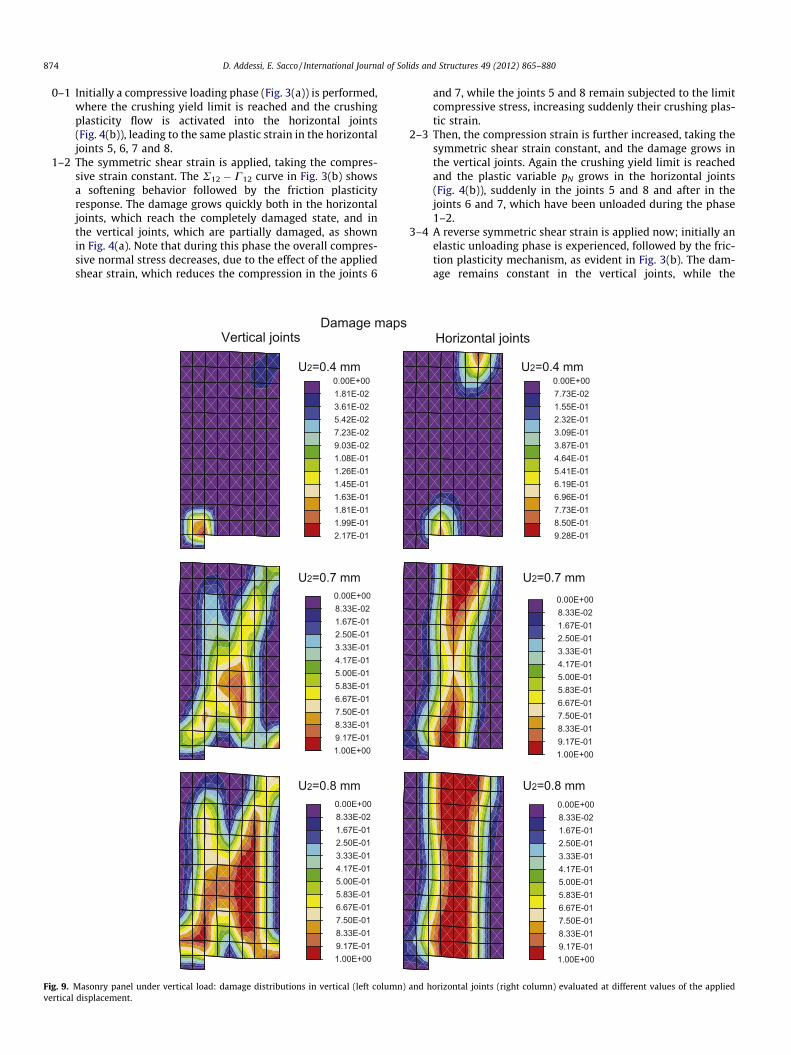
Fig. 9. Masonry panel under vertical load: damage distributions in vertical (left columnvertical displacement.
and 7, while the joints 5 and 8 remain subjected to the limitcompressive stress, increasing suddenly their crushing plas-tic strain.
2–3 Then, the compression strain is further increased, taking thesymmetric shear strain constant, and the damage grows inthe vertical joints. Again the crushing yield limit is reachedand the plastic variable pN grows in the horizontal joints(Fig. 4(b)), suddenly in the joints 5 and 8 and after in thejoints 6 and 7, which have been unloaded during the phase1–2.
3–4 A reverse symmetric shear strain is applied now; initially anelastic unloading phase is experienced, followed by the fric-tion plasticity mechanism, as evident in Fig. 3(b). The dam-age remains constant in the vertical joints, while the
Horizontal jointss
U2=0.4 mm
U2=0.7 mm
U2=0.8 mm
7.73E-02 1.55E-01 2.32E-01 3.09E-01 3.87E-01 4.64E-01 5.41E-01 6.19E-01 6.96E-01 7.73E-01 8.50E-01
0.00E+00
9.28E-01
8.33E-02 1.67E-01 2.50E-01 3.33E-01 4.17E-01 5.00E-01 5.83E-01 6.67E-01 7.50E-01 8.33E-01 9.17E-01
0.00E+00
1.00E+00
8.33E-02 1.67E-01 2.50E-01 3.33E-01 4.17E-01 5.00E-01 5.83E-01 6.67E-01 7.50E-01 8.33E-01 9.17E-01
0.00E+00
1.00E+00
) and horizontal joints (right column) evaluated at different values of the applied
D. Addessi, E. Sacco / International Journal of Solids and Structures 49 (2012) 865–880 875
plastic variable pN grows rapidly in the joints 6 and 7,remaining constant in the joints 5 and 8, which resultunloaded during this phase.
4–5 The compression strain reaches its final value (Fig. 3(b)). Thedamage does not evolve anymore, while crushing plasticityincreases in the joints 6 and 7.
5–6 A final unloaded shear phase follows, until the overall shearstress R12 becomes zero. Now both the damage and the plas-ticity do not evolve. The overall compressive stress R2
decreases due to the unloading of the joints 6 and 7.
5.2. Micromechanical vs multi-scale analysis of a masonry panel
The structural response of the masonry panel shown in Fig. 5 isfirstly analyzed. The sizes of the panel are: width B = 3290 mm,
Rigid rotation
U2=0.4 mm
U2=0.7 mm
U2=0.8 mm
-1.79E-03-1.62E-03-1.46E-03-1.30E-03-1.13E-03-9.68E-04-8.05E-04-6.42E-04-4.78E-04-3.15E-04-1.51E-04
-1.95E-03
1.20E-05
-2.69E-03-2.43E-03-2.17E-03-1.91E-03-1.64E-03-1.38E-03-1.12E-03-8.56E-04-5.93E-04-3.30E-04-6.76E-05
-2.96E-03
1.95E-04
-3.22E-03-2.87E-03-2.53E-03-2.19E-03-1.84E-03-1.50E-03-1.15E-03-8.10E-04-4.66E-04-1.22E-04 2.21E-04
-3.56E-03
5.65E-04
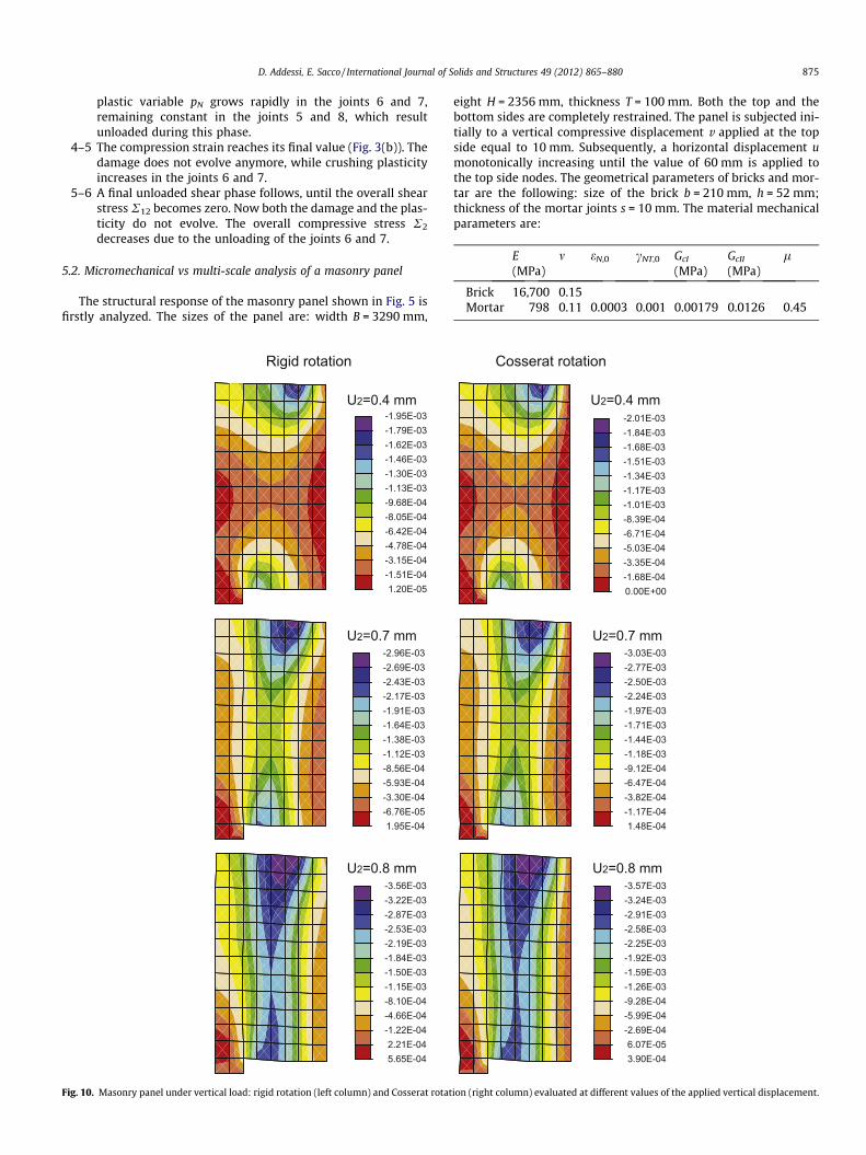
Fig. 10. Masonry panel under vertical load: rigid rotation (left column) and Cosserat rotat
eight H = 2356 mm, thickness T = 100 mm. Both the top and thebottom sides are completely restrained. The panel is subjected ini-tially to a vertical compressive displacement v applied at the topside equal to 10 mm. Subsequently, a horizontal displacement umonotonically increasing until the value of 60 mm is applied tothe top side nodes. The geometrical parameters of bricks and mor-tar are the following: size of the brick b = 210 mm, h = 52 mm;thickness of the mortar joints s = 10 mm. The material mechanicalparameters are:
ion
Co
(right col
E(MPa)
sserat
umn) evalu
m
rotat
ated at
eN,0
ion
U2=0.4
U2=0.7
U2=0.8
-1.-1.-1.-1.-1.-1.-8.-6.-5.-3.-1.
-2.
0.
-2-2-2-1-1-1-1-9-6-3-1
-3
1
-3-2-2-2-1-1-1-9-5-2 6
-3
3
different v
cNT,0
mm
mm
mm
84E-0368E-0351E-0334E-0317E-0301E-0339E-0471E-0403E-0435E-0468E-04
01E-03
00E+00
.77E-03
.50E-03
.24E-03
.97E-03
.71E-03
.44E-03
.18E-03
.12E-04
.47E-04
.82E-04
.17E-04
.03E-03
.48E-04
.24E-03
.91E-03
.58E-03
.25E-03
.92E-03
.59E-03
.26E-03
.28E-04
.99E-04
.69E-04
.07E-05
.57E-03
.90E-04
alues of
GcI
(MPa)
the applied v
GcII
(MPa)
ertical displ
l
Brick
16,700 0.15 Mortar 798 0.11 0.0003 0.001 0.00179 0.0126 0.45acement.
of Solids and Structures 49 (2012) 865–880
where E and m are Young’s and Poisson moduli, respectively, and aconstant friction parameter is considered, while the crushing plas-
ticity is neglected. The numerical response evaluated by adoptingthe presented multi-scale model is compared with the results ob-tained by performing a micromechanical analysis, where bricksand mortar are discretized separately by 4-node quadrilateral Cau-chy FEs assuming the constitutive laws presented in Section 2.2. Asconcerning the multi-scale analysis, two different meshes are876 D. Addessi, E. Sacco / International Journal
Σ1
U2=0.4 mm U2=0.7 mm
Σ2
U2=0.4 mm U2=0.7 mm
Σ12
U2=0.4 mm U2=0.7 mm
-1.55E+00-1.33E+00-1.12E+00-9.04E-01-6.90E-01-4.76E-01-2.62E-01-4.85E-02 1.65E-01 3.79E-01 5.93E-01
-1.76E+00
8.07E-01
-3.23E+00-2.90E+00-2.57E+00-2.24E+00-1.91E+00-1.58E+00-1.25E+00-9.15E-01-5.84E-01-2.53E-01 7.80E-02
-3.56E+00
4.09E-01
-1.38E+00-1.22E+00-1.07E+00-9.13E-01-7.58E-01-6.04E-01-4.50E-01-2.96E-01-1.41E-01 1.28E-02 1.67E-01
-1.53E+00
3.21E-01
Fig. 11. Masonry panel under vertical load: macroscopic stresses R1 (first row), R2 (sedisplacement.
adopted with 15 � 11 and 20 � 15 FEs, respectively, while 39,710FEs are used for the micromechanical discretization with 152,760degrees of freedom. In Fig. 6 the global response curves are reportedshowing the base horizontal reaction versus the top applied hori-zontal displacement. The solid line refers to the micromechanicalresult, while the lines with symbols refer to the multi-scale analysesperformed with the 15 � 11 (line with diamonds) and 20 � 15 (linewith squares) meshes and restraining completely the degrees of
U2=0.8 mm
U2=0.8 mm
U2=0.8 mm
-1.93E+00-1.66E+00-1.38E+00-1.10E+00-8.29E-01-5.53E-01-2.77E-01-1.58E-03 2.74E-01 5.50E-01 8.26E-01
-2.21E+00
1.10E+00
-1.97E+00-1.69E+00-1.41E+00-1.13E+00-8.52E-01-5.73E-01-2.93E-01-1.44E-02 2.65E-01 5.44E-01 8.23E-01
-2.25E+00
1.10E+00
-4.48E+00-4.04E+00-3.59E+00-3.15E+00-2.70E+00-2.26E+00-1.81E+00-1.37E+00-9.25E-01-4.80E-01-3.56E-02
-4.93E+00
4.09E-01
-4.35E+00-3.92E+00-3.48E+00-3.05E+00-2.62E+00-2.18E+00-1.75E+00-1.32E+00-8.84E-01-4.50E-01-1.71E-02
-4.78E+00
4.16E-01
-1.87E+00-1.67E+00-1.47E+00-1.28E+00-1.08E+00-8.80E-01-6.82E-01-4.84E-01-2.86E-01-8.78E-02 1.10E-01
-2.07E+00
3.08E-01
-1.83E+00-1.64E+00-1.44E+00-1.25E+00-1.05E+00-8.54E-01-6.58E-01-4.61E-01-2.65E-01-6.90E-02 1.27E-01
-2.03E+00
3.23E-01
cond row) and R12 (third row) evaluated at different values of the applied vertical

D. Addessi, E. Sacco / International Journal of Solids and Structures 49 (2012) 865–880 877
freedom at the top and bottom sides; the line with crosses refers tothe 20 � 15 mesh where only the two translational degrees of free-dom are restrained at the horizontal sides. Note that a very goodagreement is obtained in the initial elastic branch, while the curvesobtained with the multi-scale model depart a little from the micro-mechanical results in the nonlinear range, due to the capability ofthe micromechanical model of describing more accurately the non-linear damaging and plasticity mechanisms. Furthermore, it ap-pears that when the rotation degree of freedom is not restrained
ZU2=0.4 mm U2=0.7 mm
U2=0.4 mm U2=0.7 mm
M2
U2=0.4 mm U2=0.7 mm
M1
-1.99E+00-1.73E+00-1.47E+00-1.21E+00-9.57E-01-6.99E-01-4.41E-01-1.83E-01 7.54E-02 3.33E-01 5.91E-01
-2.25E+00
8.49E-01
-2.48E+00-1.49E+00-5.02E-01 4.85E-01 1.47E+00 2.46E+00 3.44E+00 4.43E+00 5.42E+00 6.41E+00 7.39E+00
-3.46E+00
8.38E+00
-4.84E+00-4.06E+00-3.29E+00-2.51E+00-1.74E+00-9.61E-01-1.85E-01 5.90E-01 1.37E+00 2.14E+00 2.92E+00
-5.61E+00
3.69E+00
Fig. 12. Masonry panel under vertical load: macroscopic stresses Z (first row), M1 (secdisplacement.
at the horizontal sides (line with crosses) the multi-scale model fitsbetter the nonlinear micromechanical response.
5.3. Masonry panel under vertical load
The masonry panel acting as a deep beam shown in Fig. 7 wasanalyzed experimentally by Grande et al. (2008). The dimensionsof the panel are: width B = 290 mm, eight H = 270 mm, thicknessT = 30 mm. In the experimental tests the panel was restrained at
U2=0.8 mm
U2=0.8 mm
U2=0.8 mm
-2.54E+00-2.19E+00-1.85E+00-1.51E+00-1.17E+00-8.29E-01-4.88E-01-1.47E-01 1.94E-01 5.36E-01 8.77E-01
-2.88E+00
1.22E+00
-2.52E+00-2.18E+00-1.85E+00-1.51E+00-1.17E+00-8.38E-01-5.01E-01-1.65E-01 1.72E-01 5.08E-01 8.45E-01
-2.86E+00
1.18E+00
-5.20E+00-3.63E+00-2.06E+00-4.85E-01 1.09E+00 2.66E+00 4.23E+00 5.80E+00 7.37E+00 8.94E+00 1.05E+01
-6.77E+00
1.21E+01
-6.79E+00-4.94E+00-3.09E+00-1.23E+00 6.24E-01 2.48E+00 4.33E+00 6.19E+00 8.04E+00 9.90E+00 1.18E+01
-8.65E+00
1.36E+01
-6.02E+00-5.17E+00-4.31E+00-3.45E+00-2.59E+00-1.73E+00-8.66E-01-6.32E-03 8.53E-01 1.71E+00 2.57E+00
-6.88E+00
3.43E+00
-5.39E+00-4.59E+00-3.79E+00-2.99E+00-2.19E+00-1.39E+00-5.94E-01 2.04E-01 1.00E+00 1.80E+00 2.60E+00
-6.18E+00
3.40E+00
ond row) and M2 (third row) evaluated at different values of the applied vertical
878 D. Addessi, E. Sacco / International Journal of Solids and Structures 49 (2012) 865–880
the bottom side with two steel rollers and the vertical externalload was applied through steel plates located on the top side ofthe panel as shown in Fig. 7. The geometrical parameters of bricksand mortar are the following: size of the brick b = 56 mm,h = 15 mm; thickness of the mortar joints s = 2 mm. Furthermore,the material mechanical parameters are:
q = 0.30 MPa
u
B
H
Fig. 13. Shearing masonry wall: geometry and boundary conditions.
0 1 2 3 4 5Top Displacement [mm]
0
20
40
60
Base
Rea
ctio
n [N
]
experimentalmesh 15x15mesh 20x20mesh 30x30
Fig. 14. Shearing masonry wall: global response curve.
E (MPa) m eN,0 cNT,0 GcI (MPa) GcII (MPa) li lf d ry (MPa) a (MPa)
Brick 1850 0.15Mortar 233 0.15 0.0015 0.004 0.00096 0.0057 0.4 0.35 3.0 5 0
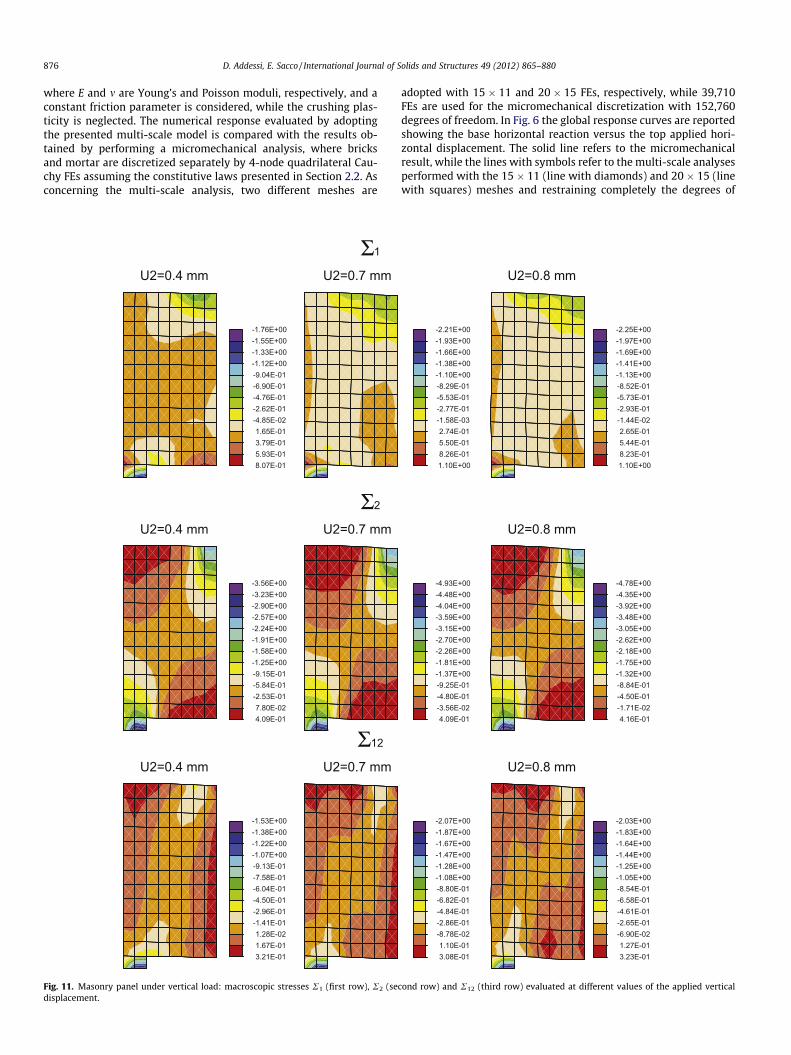
where E and m are Young’s and Poisson moduli, respectively. Due tothe symmetry of the problem, only one half of the panel is analyzedand two meshes with 74 (Fig. 7a) and 98 (Fig. 7b) FEs are adopted.A distributed vertical displacement is applied at the last threenodes of the top side. The steel rollers are discretized by meansof 4-node quadrilateral FEs, assuming a linear elastic constitutivelaw with Young’s modulus equal to 210,000 MPa and Poisson mod-ulus 0.3. In Fig. 8 the global response curve of the panel is shown,i.e. the global vertical reaction computed at the restrained node ofthe bottom side versus the top applied displacement is depicted.The three different curves shown refer to the numerically obtainedresults (solid and dashed lines) and the experimental ones (linewith diamond symbols). As it can be noted the numerical curvesare in a good agreement with the experimental one. In order to ob-tain a macroscopic homogenized evaluation of the damage variablein the RVE, two average damage variables are computed, one cor-responding to the damage distribution in the horizontal joints, theother to the damage in the vertical points. Then, in Fig. 9 the distri-butions of the damage variable are reported for the vertical headjoints (left column) and the horizontal bed joints (right column),respectively, and at three values of the applied vertical displace-ment, U2 = 0.4 mm, U2 = 0.7 mm and U2 = 0.8 mm, correspondingto the activation of the damage mechanisms, the reaching of thepeak load value and the initiation of the softening phase. The initiallinear elastic behavior is followed by a nonlinear hardening phaseduring which the damage starts first in the horizontal joints (atU2 = 0.3 mm approximately) in the two regions located at the bot-tom, near the steel rollers, and at the top, near the ends of the steelplate, where the load is applied. Then, damage appears also in thevertical joints located near the bottom side mainly concentrated atthe right corner, i.e. at the centre of the side where the flexuraldeformation state is more important. The global response curvereaches a peak load of 760 da N which matches very well theexperimental value, at the applied displacement value of 0.7 mm.After that the global response curve shows a softening trend, dur-ing which the damage in both the horizontal and vertical jointsspreads in a vertical band corresponding to the formation of themicro-fracture mechanisms typical of the experimental test. InFig. 10 the distributions of the rigid rotation W and the Cosseratrotation component U is shown at the same values of the imposedvertical displacement. Although the distributions of the two rota-tions appear similar, the values of the Cosserat rotation in the pa-nel differ from the ones of the rigid rotation, showing that themicropolar Cosserat model adopted at the macro-level allows todescribe the rotational deformation of the RVE, which is relevantin this example and is on the other hand neglected by the standardCauchy model. Lastly, in Figs. 11 and 12 the homogenized macro-scopic stress components are reported. In particular, in Fig. 11the Cauchy in-plane stresses R1, R2 and R12 are shown, whileFig. 12 contains the additional Cosserat stress components Z, M1
and M2. Note that the maximum values of the micro-couples ap-pear near the end zones of the loaded and restrained areas, wherealso the rotations are relevant.
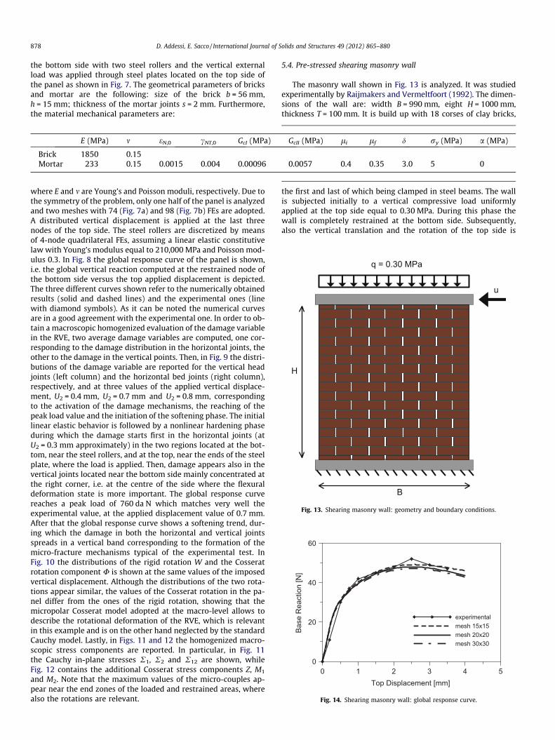
5.4. Pre-stressed shearing masonry wall
The masonry wall shown in Fig. 13 is analyzed. It was studiedexperimentally by Raijmakers and Vermeltfoort (1992). The dimen-sions of the wall are: width B = 990 mm, eight H = 1000 mm,thickness T = 100 mm. It is build up with 18 corses of clay bricks,
the first and last of which being clamped in steel beams. The wallis subjected initially to a vertical compressive load uniformlyapplied at the top side equal to 0.30 MPa. During this phase thewall is completely restrained at the bottom side. Subsequently,also the vertical translation and the rotation of the top side is
Damage distribution in horizontal joints
Damage distribution in vertical joints
U1=1 mm U1=3 mm
U1=1 mm U1=3 mm
5.76E-02 1.15E-01 1.73E-01 2.30E-01 2.88E-01 3.46E-01 4.03E-01 4.61E-01 5.18E-01 5.76E-01 6.33E-01
0.00E+00
6.91E-01
8.09E-02 1.62E-01 2.43E-01 3.24E-01 4.04E-01 4.85E-01 5.66E-01 6.47E-01 7.28E-01 8.09E-01 8.90E-01
0.00E+00
9.71E-01
8.19E-02 1.64E-01 2.46E-01 3.28E-01 4.10E-01 4.92E-01 5.73E-01 6.55E-01 7.37E-01 8.19E-01 9.01E-01
0.00E+00
9.83E-01
7.76E-02 1.55E-01 2.33E-01 3.10E-01 3.88E-01 4.65E-01 5.43E-01 6.21E-01 6.98E-01 7.76E-01 8.53E-01
0.00E+00
9.31E-01
Fig. 15. Shearing masonry wall: damage distributions in horizontal (first line) and vertical joints (second line) evaluated at different values of the applied horizontaldisplacement.
D. Addessi, E. Sacco / International Journal of Solids and Structures 49 (2012) 865–880 879
restrained and a horizontal leftward displacement monotonicallyincreasing until the value of 4 mm is applied to these nodes. Thegeometrical parameters of bricks and mortar are the following:size of the brick b = 210 mm, h = 52 mm; thickness of the mortarjoints s = 10 mm. Furthermore, the material mechanical parame-ters are:
E (MPa) m eN,0 cNT,0 GcI (MPa) GcII (MPa) li lf d ry (MPa) a (MPa)
Brick 16,700 0.15Mortar 798 0.11 0.0003 0.001 0.00179 0.0126 0.47 0.01 2.5 5 0
where E and m are Young’s and Poisson moduli, respectively. Threedifferent meshes are adopted with 15 � 15, 20 � 20 and 30 � 30FEs, respectively. To model the top steel beam 4-node quadrilateralFEs are used, assuming a linear elastic constitutive law withYoung’s modulus equal to 167,000 MPa and Poisson modulus0.15. In Fig. 14 the global response curve of the wall is reported.In particular, the global horizontal reaction computed at the bot-tom side versus the top applied displacement is depicted. Four dif-ferent curves are shown referring to the numerically obtainedresults and the experimental ones (line with diamond symbols).It is evident that the numerical curves match very well the exper-imental one. Furthermore, the dash line curve referring to the15 � 15 mesh is not a perfectly converged solution, while the solidand dash-dot line curves referring to the finer mesh are undistin-guishable, so proving the capability of the Cosserat model adoptedat the macro-level to lead to mesh-independent FE results. Afterthe initial linear elastic behavior, the nonlinear mechanisms areactivated and the global response curve reaches a peak load ofaround 48 N, a little lower than the experimentally calculatedone, at the applied displacement value of 2.5 mm. Then, the globalresponse curve shows a softening trend. In Fig. 15 the map of the
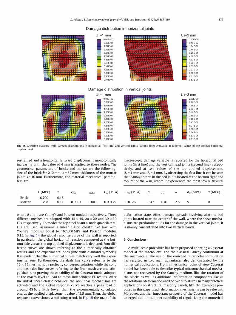
macroscopic damage variable is reported for the horizontal bedjoints (first line) and the vertical head joints (second line), respec-tively, and at two values of the top applied displacement,U1 = 1 mm and U1 = 3 mm. By observing the first line, it can be seenthat damage starts in the bed joints located at the bottom right andtop left of the wall, where it experiences the most severe flexural
deformation state. After, damage spreads involving also the bedjoints located near the center of the wall, where the shear mecha-nisms are predominant. As for the damage in the vertical joints, itis mainly concentrated into two vertical bands.
6. Conclusions
A multi-scale procedure has been proposed adopting a Cosseratmodel at the macro-level and the classical Cauchy continuum atthe micro-scale. The use of the enriched micropolar formulationhas resulted in two main advantages also demonstrated by thenumerical applications. From a mechanical point of view Cosseratmodel has been able to describe typical micromechanical mecha-nisms not recovered by the Cauchy medium, like the rotation ofthe blocks as well as additional deformation components like asthe rotational deformation and the two curvatures. In many practicalapplications on structural masonry panels, like the examples pro-posed in this paper, such deformation mechanisms can be relevant.Moreover, another important property of the Cosserat model hasemerged due to the inner capability of regularizing the numerical
880 D. Addessi, E. Sacco / International Journal of Solids and Structures 49 (2012) 865–880
FE response in presence of strain-softening behavior, at least whenthe damaging mechanisms are of shearing type. This has been clearlyshowed in one of the numerical applications presented. It is worth-while noting that the inner regularization properties of the Cosseratformulation have avoided the adoption of a numerical regularizationtechnique and the related identification of the characteristic length,since it naturally arises from the adopted formulation with a clearmechanical meaning. In the spirit of the multi-scale modeling, coarseFE discretizations should be chosen in order to get the size of the FEsgreater than the microstructural characteristic length. Nevertheless,considering the different FE meshes adopted in the numerical exam-ples for reproducing experimental tests, it is important to underlinethat they have been selected to accurately model the boundary con-ditions, i.e. loads and restraints. The two experimental examplesreproduced in this paper have been selected since the experimentaldata were available in literature (example presented in Section 5.4),or it concerned an in-house experimental test (example presented inSection 5.3).
At the micro-level a damage-plastic constitutive model hasbeen introduced capable to describe the main relevant microme-chanical inelastic mechanisms such as the damage, the frictionplasticity and the crushing of the mortar joints, while the inelasticbehavior of the blocks has not been considered. In particular, theformulation of the constitutive model proposed has been enrichedwith respect to the one adopted in previous papers by the sameauthors, considering here also the crushing plasticity mechanismsand a degrading exponential law for the friction parameter, consis-tent with the experimental results. The presented multi-scale for-mulation based on the TFA homogenization technique has resultedvery effective from a computational point of view, since it has al-lowed to reduce considerably the computational burden with re-spect to the standard homogenization procedures, avoiding tosolve nested micromechanical FE problems at each Gauss pointof the macro-level discretization. At the same time it has been ableto analyze interesting structural cases describing also the details ofthe micromechanical mechanisms and giving results in a greatagreement with the experimental ones.
References
Addessi, D., Sacco, E., Paolone, A., 2010. Cosserat model for periodic masonrydeduced by nonlinear homogenization. European Journal of Mechanics – A/Solids 29, 724–737.
Alfano, G., Sacco, E., 2006. Combining interface damage and friction in a cohesive-zone model. International Journal for Numerical Methods in Engineering 68 (5),542–582.
Anthoine, A., 1995. Derivation of the in-plane elastic characteristics of masonrythrough homogenization theory. International Journal of Solids and Structures32 (2), 137–163.
Bacigalupo, A., Gambarotta, L., 2011. Second-order computational homogenizationof heterogeneous materials with periodic microstructure. ZAMM: Journal ofApplied Mathematics and Mechanics 90 (10-11), 796811.
Bazant, Z., Planas, J., 1998. Fracture and Size Effects in Concrete and OtherQuasibrittle Materials. CRC Press LLC.
Brasile, S., Casciaro, R., Formica, G., 2007a. Multilevel approach for brick masonrywalls. Part i: A numerical strategy for the nonlinear analysis. ComputerMethods in Applied Mechanics and Engineering 196, 4934–4951.
Brasile, S., Casciaro, R., Formica, G., 2007b. Multilevel approach for brick masonrywalls. Part ii: On the use of equivalent continua. Computer Methods in AppliedMechanics and Engineering 196, 4801–4810.
Casolo, S., 2006. Macroscopic modelling of structured materials: relationshipbetween orthotropic Cosserat continuum and rigid elements. InternationalJournal of Solids and Structures 43 (3–4), 475–496.
Cavalagli, N., Cluni, F., Gusella, V., 2011. Strength domain of non-periodic masonryby homogenization in generalized plane state. European Journal of Mechanics –A/Solids 30, 113–126.
Cecchi, A., Sab, K., 2009. Discrete and continuous models for in plane loaded randomelastic brickwork. European Journal of Mechanics – A/Solids 28, 610–625.
De Bellis, M., Addessi, D., 2011. A Cosserat based multi-scale model for masonrystructures. International Journal for Computational Engineering 9 (5), 543–563.
Dvorak, G., 1992. Transformation field analysis of inelastic composite materials.Proceedings of the Royal Society of London A 437, 311–327.
Fish, J., Shek, K., 2000. Multiscale analysis of composite materials and structures.Composites Science and Technology 60, 2547–2556.
Forest, S., Sab, K., 1998. Cosserat overall modelling of heterogeneous materials.Mechanics Research Communications in Numerical Methods in Engineering 4,449–454.
Gambarotta, L., Lagomarsino, S., 1997a. Damage models for the seismic response ofbrick masonry shear walls. Part i: The mortar joint model and its application.Earthquake Engineering and Structural Dynamics 26, 423–439.
Gambarotta, L., Lagomarsino, S., 1997b. Damage models for the seismic response ofbrick masonry shear walls part ii: the continuum model and its application.Earthquake Engineering and Structural Dynamics 26, 441–462.
Grande, E., Milani, G., Sacco, E., 2008. Modelling and analysis of frp-strengthenedmasonry panels. Engineering Structures 30, 18421860.
Kouznetsova, V.G., Geers, M.G.D., Brekelmans, W.A.M., 2002. Multi-scaleconstitutive modelling of heterogeneous materials with a gradient-enhancedcomputational homogenization scheme. International Journal for NumericalMethods in Engineering 54, 1235–1260.
Linder, C., Armero, F., 2007. Finite elements with embedded strong discontinuitiesfor the modeling of failure in solids. International Journal for NumericalMethods in Engineering 72 (12), 1391–1433.
Luciano, R., Sacco, E., 1998. Variational methods for the homogenization of periodicheterogeneous media. European Journal of Mechanics – A/Solids 17 (4), 599–617.
Masiani, R., Rizzi, R., Trovalusci, P., 1995. Masonry as structured continuum.Meccanica 30 (6), 673–683.
Masiani, R., Trovalusci, P., 1996. Cauchy and Cosserat materials as continuummodels of brick masonry. Meccanica 31 (4), 421432.
Massart, T.J., Peerlings, R.H.J., Geers, M.G.D., 2007. An enhanced multi-scaleapproach for masonry wall computations with localization of damage.International Journal for Numerical Methods in Engineering 69 (5), 1022–1059.
Massart, T.J., Peerlings, R.H.J., Geers, M.G.D., Gottcheiner, S., 2005. Mesoscopicmodeling of failure in brick masonry accounting for three-dimensional effects.Engineering Fracture Mechanics 72 (8), 1238–1253.
Mercatoris, B., Massart, T., 2011. A coupled two-scale computational scheme for thefailure of periodic quasi-brittle thin planar shells and its application to masonry.International Journal for Numerical Methods in Engineering 85, 1177–1206.
Pegon, P., Anthoine, A., 1997. Numerical strategies for solving continuum damageproblems with softening: application to the homogenization of masonry.Computers and Structures 64, 623–642.
Ragueneau, F., La Borderie, C., Mazars, J., 2000. Damage model for concrete-likematerials coupling cracking and friction, contribution towards structuraldamping: first uniaxial applications. Mechanics of Cohesive-FrictionalMaterials 5 (8), 607–625.
Raijmakers, T.M.J., Vermeltfoort, A.T., 1992. Deformation controlled tests inmasonry shear walls. Report B-92-1156. TNO-Bouw, Delft, The Netherlands.
Sab, K., Pradel, F., 2009. Homogenisation of periodic Cosserat media. InternationalJournal of Computer Applications in Technology 34 (1), 60–71.
Sacco, E., 2009. A nonlinear homogenization procedure for periodic masonry.European Journal of Mechanics – A/Solids 28 (2), 209–222.
Salerno, G., de Felice, G., 2009. Continuum modeling of periodic brickwork.International Journal of Solids and Structures 46 (5), 1251–1267.
Simo, J., Hughes, T.J.R., 1998. Computational Inelasticity. Springer, New York.Suquet, P., 1987. Elements of homogenization for inelastic solid mechanics. In:
Homogenization Techniques for Composite Media. Springer-Verlag, Berlin.Taylor, R., 2011. FEAP – a finite element analysis program, Version 8.3. Department
of Civil and Environmental Engineering, University of California at Berkeley,California.
Terada, K., Hori, M., Kyoya, T., Kikuchi, N., 2000. Simulation of the multi-scaleconvergence in computational homogenization approach. International Journalof Solids and Structures 37, 2285–2311.
Trovalusci, P., Masiani, R., 1999. Material symmetries of micropolar continuaequivalent to lattices. International Journal of Solids and Structures 36 (14),2091–2108.
van der Sluis, O., Schreurs, P.J.G., Brekelmans, W.A.M., Meijer, H.E.H., 2000. Overallbehaviour of heterogeneous elastoviscoplastic materials: effect ofmicrostructural modelling. Mechanics of Materials 32, 449–462.
Wei, X., Hao, H., 2009. Numerical derivation of homogenized dynamic masonrymaterial properties with strain rate effects. International Journal of ImpactEngineering 36, 522–536.
Zucchini, A., Lourenco, P., 2009. A micromechanical homogenisation model formasonry: Application to shear walls. International Journal of Solids andStructures 46 (3–4), 871–886.