a model for strain-temperature loops in shape memory … · a model for strain-temperature loops in...
TRANSCRIPT

A MODEL FOR STRAIN-TEMPERATURE LOOPS IN SHAPE MEMORY ALLOY ACTUATORS Maria Marony S. F. Nascimento José Sérgio da Rocha Neto Antonio Marcus Nogueira de Lima Departamento de Engenharia Elétrica Universidade Federal de Campina Grande Cep: 58109-970 Campina Grande – PB Brazil Luis A. L. de Almeida Departamento de Engenharia Elétrica Universidade Federal da Bahia Salvador – BA Brazil Carlos José de Araújo Departamento de Engenharia Mecânica Universidade Federal de Campina Grande Cep: 58109-970 Campina Grande – PB Brazil [email protected] Abstract: In this paper, a hysteresis model, originally developed for magnetic hysteresis and adapted to thermal hysteresis in vanadium dioxide (VO2) thin films, is proposed to describe the hysteresis in the ε-T characteristics of a SMA actuator. In order to determine the strain (ε) - Temperature (T) behavior of a Ti-Ni SMA wire actuator (78mm in length and 150µm in diameter) an experimental set-up was implemented. The SMA wire is loaded with a weight providing a constant uniaxial tensile stress and is heated electrically. In the absence of an accurated and reliable technique for measurement of the SMA wire temperature, such temperature is estimated from the electrical current using the static thermal equilibrium equation for the steady-state. External room temperature disturbances are greatly reduced by embedding the wire in a heat-insulating medium. The control of the heating electrical current through the wire and measurement of the steady-state wire deformation with an LVDT displacement sensor having a resolution of 5µm, was done using GPIB compatible instruments. The results of these measurements, for ε-T major loops and first order descending curves, are presented together with the data calculated with the proposed model. Model simulations have shown good agreement with the experimental data. Keywords: Shape memory alloy actuators, hysteresis models, smart materials.
1. Introduction
Shape memory alloys (SMA) have been considered one of the more interesting smart material systems, with a great potential for applications in some modern active structures, mainly as electrical or thermal actuator (Srinivasan and McFarland, 2001). Previously strained SMA actuator recover its original shape when heated above a critical temperature. In the case of SMA wire actuators under uniaxial tensile mechanical load, this shape recovery corresponds to a contraction and the actuator provides a useful external mechanical work. However, the thermoelastic martensitic transformation at the origin of this shape memory effect (SME) is characterized by four transformation temperatures (Ms, Mf, As e Af, typically in raising order) describing a hysteresis loop between two crystalline structures (Otsuka and Wayman, 1998). Then, the trajectory of the actuator is nonlinear and accompanied by a hysteresis. Thus, the analysis, design and optimization of a SMA actuator are critically dependent on the availability of a strain (ε) – temperature (T) hysteresis model that can mathematically describe this characteristic including both major and minor loops. Ortin and Delaey (2002) present an overview of hysteresis phenomena in the martensitic transformation, and their relevance in the thermomechanical behaviour of shape-memory alloys. A great number of constitutive models have been based on phenomenological continuum mechanics and plasticity (Helm and Haupt, 2003; Aurichio and Lubliner, 1997; Aurichio et al., 1997; Aurichio and Sacco, 1997) and many others are based on a kinetic law governing the phase transformation behavior (Tanaka and Nagaki, 1982; Tanaka, 1986; Liang and Rogers, 1990; Brinson, 1993; Boyd and Lagoudas, 1994). The former models are mathematically complex and generally multidimensional while the later are of easy implementation and have been successfully applied for the analysis and design of some SMA active structures. Comparisons of SMA constitutive models with assumed transformation kinematics has demonstrated differences and a more realistic performance of the Brinson model (Paiva and Savi, 1999). For control purposes, Gorbet (1997) and Majima et al. (2001) proposed a model for phase transformation based on modification of the Preisach model. However, some recent results with Preisach models (Ktena et al., 2001 and 2002) have shown discrepancies attributed to the choice of hysteresis operators.

Additionally, sometimes the wiping-out and congruency properties (Mayergoyz, 1991) required for the application of the Preisach formalism are not observed in the ε - T SMA hysteresis and this model cannot be used (Nascimento, 2002).
In this paper, it is proposed an adaptation of the Limiting Loop Proximity (L2P) hysteresis model, recently developed by Almeida et al. (2002) for magnetic hysteresis and later adapted to thermal hysteresis in VO2 thin films (Almeida et al., 2002), to describe hysteretic ε - T characteristics of a SMA actuator. All parameters necessary for the modeling procedure was determined using an experimental set-up especially designed for this study.
2. Modelling the εεεε - T hysteretic behavior
Figure (1) shown a schematic representation of typical hysteresis in ε - T characteristics of a SMA wire actuator. Hysteresis trajectories corresponding to low temperatures excursions are usually confined inside the major limiting loop, which is the combination of the descending and ascending limiting curves. Based on the models developed by Almeida et al. (2002), the following function FL(T) for the ε(T) behavior is proposed
022arctan)()( επδβ
πεε +
+
−+== TTwTFT c
sL (1)
to describe the strain ε pertaining to the major descending and ascending limiting curves. In this equation T is the excitation
temperature, ε0 is the saturation strain, εs is the hysteresis height, w is the hysteresis width, β is related with dTdε
at Tc, where Tc
is the critical temperature at the center of the hysteresis curve. δ is an operator defined as
=
.sgn Tδ . The combination of
the curves FL(T, δ = +1) and FL(T, δ = -1) describes the major hysteresis loop in the ε - T plane.
Figure 1. Schematic representation of hya reversal curves illustrates the concept o
Reversal curves, minor loops and n
represent the dependence ε(T) for any trimportant to take into account the way in(1), where the change in the sign of dT/dis reversed, and k starts at the reversal po
The proximity temperature Tp in Fbranch k to the corresponding point (TL,
Stra
in, ε
(%)
Stra
in, ε
(%)
)
(TL ,ε
steresis in ε - T chaf proximity of a po
ested minor loops ajectory inside the l which the inner trat that occurs in at thint (Tr, εr).
ig. (1) is introduced ε) on the limiting c
TeTe
(T, ε)
2
w/2racteristics int on the re
are not desimiting majectories ape time inst
to expresurve FL(T,
mperaturemperature
w/
of a SMA wire actuator. This geometric construction of versal curve to the limiting loop.
cribed by Eq. (1). This equation must to be modified to jor loop. To introduce this modification, it is particularly proach the major loop. This concept is illustrated in Fig.
ant tr is represented (point (Tr, εr)). Hysteresis branch k-1
s the nearness in distance of the current point (T, ε) on δ ), given as
, T(oC), T(oC)

TTT Lp −= (2)
Using Eq. (1) to obtain the value of TL corresponding to ε = FL(TL , δ )
−
−−+=
2tan1
20 π
εεεπ
βδ
ScL TwT (3)
Thus, Tp at (T, ε) as obtained from Eq. (2) is
TTwTS
cp −
−
−−+=
2tan1
20 π
εεε
πβ
δ (4)
In the beginning of a new trajectory at the reversal point (Tr, εr), the proximity function Tp is named Tpr, calculated as
follow:
rS
rcpr TTwT −
−
−−+=
2tan1
2π
εεεπ
βδ (5)
It was observed from experimental data that Tp exhibits almost the same functional dependence regardless of the reversal
point (Tr, εr) at which the reversal curve starts. Thus, to describe Tp for any branch inside the major loop, the following functional dependence is proposed :
( )xPTT prP = (6)
where
−=
pr
r
TTTx (7)
and P(x) is an arbitrary monotonically decreasing function, with P(0) = 1 and P(∞) = 0, called here the proximity function. Thus, for a hysteresis branch reversed at the point (Tr, εr) inside the major ε - T loop, the strain for any arbitrary point (T,ε) is expressed as
02)(
2arctan)( επδβ
πεε +
+
−−+= xPTTTwT prc
s (8)
and the values of δ, Tr and Tpr changes only at the reversal points, and remain unchanged until the next reversal in dT/dt occurs. For the SMA actuator employed in this study, the following proximity function is proposed
( ) cbxaa
xxP −−−−−= 1)(tanhln41
2)( 2 (9)
where a and b are arbitrary constants and c is chosen such that P(∞) = 0.

3. Experimental procedure 3.1. Experimental set-up
The SMA actuators used in this work are equiatomic Ni-Ti wires with 90mm in length and 150µm in diameter, supplied by
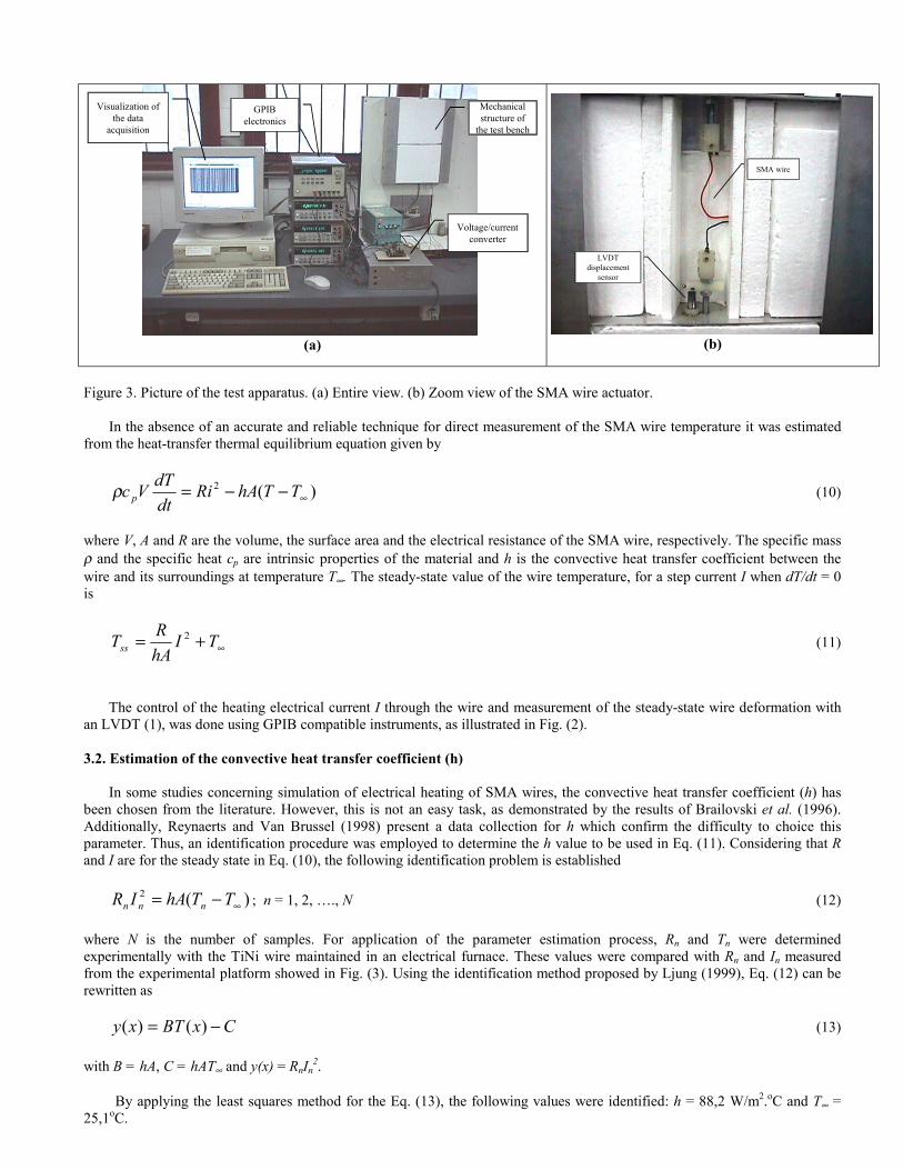
Mondo-Tronics Inc. (Gilbertson, 2000). In order to determine the ε - T characteristic of the Ni-Ti SMA wire, an experimental platform illustrated in Fig. (2) was implemented to submit the SMA wire to several heating-cooling cycles. As shown in Fig. (2), the experimental set-up has three fundamental parts: a simple mechanical structure, a voltage/current converter and a data acquisition system. In the mechanical structure of the test bench, the SMA wire (8) is loaded with a constant weight (5) and electrically heated by a voltage/current converter. A linear differential transformer (LVDT (1)) having a resolution of 5µm is used to measure the displacement of the SMA wire. External room temperature disturbances are greatly reduced by embedding the wire in a heat-insulating medium. Figure (3) shows a picture of this experimental test bench.
Figure 2. Mechanical structure of the testing bench and data acquisition system: (1) LVDT displacement sensor; (2), (3) mechanical grips; (4) guiding LVDT; (5) load (weight); (6) frame; (7) guiding rod; (8) SMA wire.
Voltage/Current Converter
Voltage LVDT
Current SMA wire
Voltage SMA wire
Multimeter HP-GPIB
Multimeter HP-GPIB
Power supply HP-GPIB
1
2,34
5
6
7
8
Voltage/Current Converter
Voltage LVDT
Current SMA wire
Voltage SMA wire
Multimeter HP-GPIB
Multimeter HP-GPIB
Power supply HP-GPIB
1
2,34
5
6
7
8
(a) (b)
Figure 3. Picture of the test apparatus. (a) Entire view. (b) Zoom view of the SMA wire actuator.
In the absence of an accurate and reliable technique for direct measurement of the SMA wire temperature it was estimated
from the heat-transfer thermal equilibrium equation given by
)(2∞−−= TThARi
dtdTVc pρ (10)
where V, A and R are the volume, the surface area and the electrical resistance of the SMA wire, respectively. The specific mass ρ and the specific heat cp are intrinsic properties of the material and h is the convective heat transfer coefficient between the wire and its surroundings at temperature T∞. The steady-state value of the wire temperature, for a step current I when dT/dt = 0 is
∞+= TIhARTss
2 (11)
The control of the heating electrical current I through the wire and measurement of the steady-state wire deformation with
an LVDT (1), was done using GPIB compatible instruments, as illustrated in Fig. (2).
3.2. Estimation of the convective heat transfer coefficient (h)
In some studies concerning simulation of electrical heating of SMA wires, the convective heat transfer coefficient (h) has been chosen from the literature. However, this is not an easy task, as demonstrated by the results of Brailovski et al. (1996). Additionally, Reynaerts and Van Brussel (1998) present a data collection for h which confirm the difficulty to choice this parameter. Thus, an identification procedure was employed to determine the h value to be used in Eq. (11). Considering that R and I are for the steady state in Eq. (10), the following identification problem is established
)(2
∞−= TThAIR nnn ; n = 1, 2, …., N (12)
where N is the number of samples. For application of the parameter estimation process, Rn and Tn were determined experimentally with the TiNi wire maintained in an electrical furnace. These values were compared with Rn and In measured from the experimental platform showed in Fig. (3). Using the identification method proposed by Ljung (1999), Eq. (12) can be rewritten as
CxBTxy −= )()( (13)
with B = hA, C = hAT∞ and y(x) = RnIn2.
By applying the least squares method for the Eq. (13), the following values were identified: h = 88,2 W/m2.oC and T∞ =
25,1oC.
Visualization of the data
acquisition
Voltage/current converter
Mechanical structure of
the test bench
GPIB electronics
Visualization of the data
acquisition
Voltage/current converter
Mechanical structure of
the test bench
GPIB electronics
SMA wire
LVDT displacement
sensor
SMA wire
LVDT displacement
sensor

4. Results and discussions
To obtain the model parameters, the SMA wire was submitted to a time-varying current excitation, composed of various monotonic segments. The wire temperatures, for a current rate of 4,78 mA/min used in all experiments, was estimated by Eq. (11), as can be verified in Fig. (4) for major and minor loops.
Figure 4. Current and temperature waveforms on the SMA wtemperature.
Figure (5) shows the strain response of the SMA actuatwere carried out for various applied load (weights) betweeand 225 MPa.
Figure 5. SME behavior of the actuator wire for several apploops.
It is observed from Fig. (5) the displacement of the ε -the SMA actuators and corresponds to an increase of the modified Clausius-Clayperon law (Otsuka and Wayman, 1MPa/oC and 4,4 MPa/oC for austenite and martensite tempvarious stress levels in Fig. (5b) is due to the fact that betwfully oriented by the external load.
From inspection of the ε - T loops shown in Fig. (5bapplied stress. However, it is not possible to determine β, a
Time (min)
Con
trac
tion
(mm
)
Time (min)
Con
trac
tion
(mm
)
Time (min)
Curr
ent (
A)
Time (min)
Curr
ent (
A)
) )
)
(a
ire actuator. (a) Excitation wire current. (b) Estimated wire
or for the major loop excitation verified in Fig. (4). The experin 2,5 and 4 N corresponding to uniaxial tensile stresses betwee
lied loads. (a) Absolute contraction of the SMA wire. (b) ε - T
T loops towards the higher temperatures. This behavior is typitransformation temperatures with the applied stress, accordin998). The calculated stress/temperature rate was of the order eratures, respectively. The same value of saturation strain (~5%een 142 and 225 MPa the martensite variants into the SMA wi
), the values of ε0, εs, w and Tc can be readily determined fo and b from inspection of experimentally obtained curves. The
Temperature (oC)
Stra
in (%
)
Temperature (oC)
Stra
in (%
)
Time (min)
Tem
pera
ture
(o C)
Time (min)
Tem
pera
ture
(o C)
(b)
(b
ments n 142
(a
cal of g to a of 6,8
) for re are
r any value

of β can be obtained by fitting both FL(T, δ = +1) and FL(T, δ = -1) to experimental major descending and ascending curves, respectively. Once the values of ε0, εs, w, Tc and β have been determined, the value of a and b in P(x) can be obtained by fitting Eq. (8) to a first-order descending ε - T curve. A first-order descending curve is generated by first increasing the current to maximum value, and then reducing the temperature monotonically until it reaches some value I such that the strain ε lies on the ascending major curve. Subsequently, the current is again increased monotonically to maximum value.
For the SMA wire employed in this study, the values obtained for the five parameters are: εs = 4,8%, ε0 = -4,6%, β = 0,3oC-
1, Tc = 71,5oC, a = 5 and b = 1,028. For the estimated temperature using Eq. (11), the parameters are: h = 88 W/m2.oC, A = 3,68x10⁻⁵ m2 and the value of R is the one measured during the experiments (Nascimento, 2002). Additionally, it was experimentally verified that hysteresis width (w) is a linear function of the applied stress (σ). From the w results obtained on Fig. (5b), it was confirmed the following relationship between w and σ :
9492,470764,0)( +−= σσw (12)
Figure (6) presents the experimental ε - T curves (solid symbols) for 200MPa together with the respective simulated behavior (solid line) for a major loop and minor loops calculated from Eq. (8) incorporating Eq. (12). These results were obtained with the excitation waveforms described in Fig. (4).
Figure 6. Response of the SMA wire actuator unexperimental and simulated major and minor loo
From Fig. (6a) and Fig. (6b) it is verifiexperimental data. To quantify the discrepancywas employed, given as
%100)(
1
_2
1
_2
xx
xxe
N
ii
N
i iiRMS
∑∑
=
=−
=
where xi represents data from the model, xi- rep
the mean error for all first-order descending ε - T
5. Conclusions In this work a phenomenological model
implemented. This model was established diredeveloped for magnetic hysteresis and later adathe form of an algebraic equation that is compuexperimentally from experimental data with regaheat transfer coefficient for temperature estima
Time (min)
Stra
in (%
)
Time (min)
Stra
in (%
)
) )
(ader 200MPa. (a) SMA strain response as a function of the timeps for the SMA wire actuator.
ed a good agreement of the data calculated with the prop between model and experimental data, the normalized root-m
resents experimental data and N is the number of data points. curves was calculated to be 5,4%.
for the SMA actuator ε - T behavior has been proposed ctly from the Limiting Loop Proximity (L2P) hysteresis app
pted to describe thermal hysterisis in VO2 thin films. This modtationally simple to implement. The parameters of this model rd to major and minor ε - T loops. Aiming a more correct resution was determined by an identification parameter procedu
Temperature (oC)
Stra
in (%
)
Temperature (oC)
Stra
in (%
)
(b. (b)
osed model and ean-square error
(13)
Using N = 1594,
and successfully roach, originally el is expressed in were determined lt, the convective re. The obtained
results can be considered satisfactory. The discrepancies between the calculated and the experimental data can be attributed to limitations in the numerical implementation of the model and to the large asymmetry of ε - T curve. The model has potential to be applied for control purposes in smart structures.
6. Acknowledgments
The authors thank CNPq/PRONEX (Conselho Nacional de Desenvolvimento Científico e Tecnológico) and CAPES (Fundação de Coordenação de Aperfeiçoamento de Pessoal de Nível Superior) for the award of research and study fellowship during the course of these investigations. 7. References Almeida, L. A. L., Deep, G. S., Lima, A. M. N. and Neff, H., 2002. “The Limiting Loop Proximity (L2P) Hysteresis Model”,
IEEE Transaction on Magnetics, Vol. 39(1), pp. 523-528. Almeida, L. A. L., Deep, G. S., Lima, A. M. N. and Neff, H., 2002. “Modeling of the Hysteretic Metal-Insulator Transition in
Vanadium Dioxide Infrared Detector”, Optical Engineering, Vol. 41(10), pp. 2582-2588. Auricchio, F. and Lubliner, J., 1997. “A Uniaxial Model for Shape Memory Alloys”, International Journal of Solids and
Structures, Vol.34, n.27, pp. 3601-3618. Auricchio, F. and Sacco E., 1997. “A One-Dimensional Model for Superelastic Shape Memory Alloys with Different Elastic
properties Between Austenite and Martensite”, International Journal of Non-Linear Mechanics, Vol. 32, n.6, pp.1101-1114 Auricchio, F., Taylor, R.L. and Lubliner, J., 1997. “Shape-Memory Alloys: Macromodeling and Numerical Simulations of the
Superelastic Behavior”, Comp. Methods in Applied Mech. and Eng., Vol.146, pp. 281-312. Boyd, J.G. and Lagoudas, D.C., 1994. “Constitutive Model for Simultaneous Transformation and Reorientation in Shape
Memory Alloys”, Mech. of Phase Transf. and Shape Memory Alloys, L.C. Brinson and B. Moran (Eds), ASME New York, pp. 159-177.
Brailovski, V., Trochu, F. and Daigneault, G., 1996. “Temporal characteristics of shape memory linear actuators and their application to circuit breakers”, Materials and Design, Vol. 17, No 3, pp. 151-158.
Brinson, L.C., 1993. “One Dimensional Constitutive Behavior of Shape Memory Alloys: Themomechanical Derivation with Non Constant Material Functions and Redefined Martensite Internal Variable”, Journal of Intelligent Materials Systems and Structures, n.4, Vol.2, pp. 229-242.
Gilbertson, R. B., 2000. “Muscle Wires Projet Book”, Mondo-Tronics Inc., 55p. Gorbet, R. B., 1997. “Control of Hysteretic Systems with Preisach Representations”. PhD Thesis: University of Waterloo,
Waterloo, Canada, 176p. Helm, D. and Haupt, P., 2003. “Shape memory behaviour: modelling within continuum thermomechanics”, International
Journal of Solids and Structures, Vol. 40, pp. 827–849. Ktena, A., Fotiadis, D.I., Spanos, P.D. and Massalas, C.V., 2001. “A Preisach model identification procedure and simulation of
hysteresis in ferromagnets and shape-memory alloys”, Physica B, Vol. 306, pp. 84–90. Ktena, A., Fotiadis, D.I., Spanos, P.D., Berger, A. and Massalas, C.V., 2002. “Identification of 1D and 2D Preisach models for
ferromagnets and shape memory alloys”, International Journal of Engineering Science, Vol. 40, pp. 2235–2247 (article in press).
Liang, C. and Rogers, C.A., 1990. “One-Dimensional Thermomechanical Constitutive Relations for Shape Memory Materials”, Journal of Intelligent Materials Systems and Structures, n. 1, Vol.2, pp. 207-234.
Ljung, L., 1999. “System Identification: Theory for the User”, Prentice Hall, Linkoping University, Sweden. Majima, S., Kodama, K. and Hasegawa, T., 2001. “Modelling of Shape Memory Alloy Actuator and Tracking Control Systems
with the Model”, IEEE Transactions on Control Systems Technology, Vol.9, pp. 54-59. Mayergoyz, I., 1991. “Mathematical Models for Hysteresis”, Springer-Verlag, 273p. Nascimento, M.M.S.F., 2002. “Contribution to the Study of Hysteresis in Shape Memory Alloys” (in Portuguese). Master of
Science Report: Universidade Federal de Campina Grande, Brazil, 79p. Ortin, J. and Delaey, L., 2002. “Hysteresis in shape-memory alloys”, International Journal of Non-Linear Mechanics, Vol. 37
pp. 1275 – 1281. Otsuka, K. and Wayman, C.M., 1998. “Shape Memory Materials”, Cambridge University Press, Cambridge, UK, 284p. Paiva, A. and Savi, M. A., 1999. “On The Constitutive Models With Assumed Transformation Kinetics For Shape Memory
Alloys” (in protuguese), Proceedings of the 15th Brazilian Congress of Mechanical Engineering, CD-ROM, Águas de Lindóia-SP, Brazil.
Reynaerts, D. and Van Brussel, H., 1998. “Design Aspects of Shape Memory Actuators”, Mechatronics, Vol. 8, pp. 635-656. Srinivasan, A.V. and McFarland, D.M., 2001. “Smart Structures – Analysis and Design”, Cambridge University Press,
Cambridge, UK, 228p. Tanaka, K. and Nagaki, S., 1982. “Thermomechanical Description of Materials with Internal Variables in the Process of Phase
Transformation”, Ingenieur – Archiv., Vol.51, pp.287-299. Tanaka, K., 1986. “A Thermomechanical Sketch of Shape Memory Effect: One – Dimensional Tensile Behavior”, Res. Mech.,
Vol. 18, pp. 251.