a method of calculating turbulent-boundary-layer growth at
TRANSCRIPT

@
By
James C. Sivells and Robert G. Payne
GDF, ARO, Inc.
A ETHOD OF CALCULATINGTURBUlE T.. BOUNDARY -LAYER GROWTH
H PERSONIC MACH NUMBERS
A.E 0G-TR-59-3ASTIA DOCUMENT NO.:AD-208774
@March 1959
L EEV L E
@
II
IL_
IR RESEARCH AND DEVELOPMENT COMMAND
US ~~AF
III
A E D C - T R - 5 9 - 3 A S T l A D O C U M E N T NO. :
AD-208774
A METHOD O F CALCULATING TURBULENT-BOUNDARY-LAYER
GROWTH AT HYPERSONIC MACH NUMBERS
BY
J a m e s C. Sivells and Rober t G. Payne
GDF, ARO, Inc.
March 1959
ARO Pro j ec t No. 347802
Contract No. A F 40(600)-700 S / A 13(59-1)

CONTENTS
Page
ABSTRACT . . . . . . . . . , . . . . . . . . . . . . . . 5 NOMENCLATURE . . . . . . . . . . . . . . . . . . . . . 5 INTRODUCTION . . . . . . . . . . . . . . . . . . . . . . 7 DEVELOPMENT OF METHOD
Momentum Equation . . . . . . . . . . . . . . . . . . 8 Determination of Cr . . . . . . . . . . . . . . . . . . 11 Determination of IIi . . . . . . . . . . . . . . . . . . 15
APPLICATION TO AXISYMMETRIC TUNNELS . . . . . . . . 17 CONCLUDING REMARKS . . . . . . . . . . . . . . . . . . 21 APPENDIXES
A. Stewartson1s Transformation . . . . . . . . . . . . . 23 B. Incompressible Skin-Friction Coefficients . . . . . . . 27
R E F E R E N C E S . . . . . . . . . . . . . . . . . . . . . . . 31
TABLE
1. Incompressible Skin Fr ic t ion Values . . . . . . . . . . . . 35
ILLUSTRATIONS
Figure
1. Tempera ture Variations Used for Correla t ing Wind Tunnel Resul ts . . . . . . . . , . . . . . . . . . . . 36
2. Correlat ion of Calculated Ratios, c f / C f i , with Experimental Values Based upon R, . . . . , . . . . . 37
3 . Correlat ion of Calculated Ratios, Cr/Cri , with Experimental Values Based upon R e . . . . . . . . . . 38
4. Values of Integral Used in Calculating Boundary-Layer Thickness at the Throat of a n Axisymmetric Nozzle . . . 39
5. Values of Integral Used in Calculating Boundary-Layer Thickness in Conical Nozzles . , . . . . . . . . . . . . 40
6. Comparison of Calculated Boundary-Layer Thickness with Values Measured in a Mach 7, 50-inch-Diameter Conical Nozzle . . . , . . . . . . . . . . . . . . . . 41
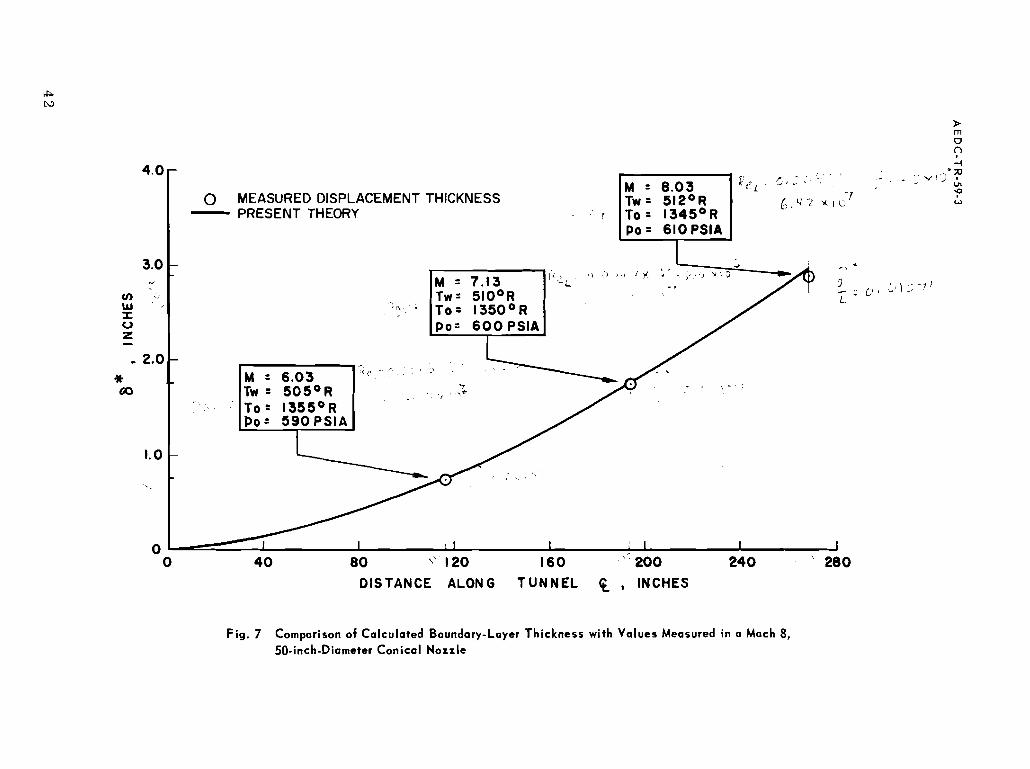
7. Comparison of Calculated Boundary-Layer Thickness with Values Measured in a Mach 8, 50-inch-Diameter Conical Nozzle . , . . . . . . . . . . . . . . , . . , 4 2

Figure Page
8. Comparison of Calculated Boundary-Layer Thickness with Value Measured in a Mach 8, 50-inch-Diameter Contoured Nozzle . . . . . . . . . . . . . . . . . . . 43
9. Correlation of Calculated Values of II with Experimental Va lues . . . . . . . . . . . . . . . . . . . . . . . . 44
10. Comparison of Values of H Calculated f rom Eq. (A-24) with Those from Ref. 26 for Hi = 11 19 . . . . . . . . . 45
11. Comparison of Various Equations for Incompressible Mean Skin-Friction Coefficient . . . . . . . . . . . . , 46
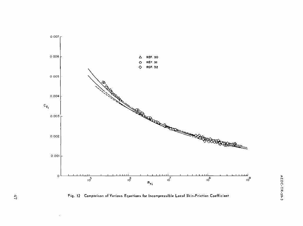
12. Comparison of Various Equations for Incompressible Local Skin-Friction Coefficient . . . . . . . . . . . . . 47
13. Comparison of Various Equations Relating R 8 , with R x i . . 48
14. Comparison of Various Equations Relating IIi with R e i . . 49
15. Comparison of Various Equations Relating Il i with Rx . . 50 i

ABSTRACT
A method is developed for calculating the growth of a turbulent boundary layer at hypersonic Mach numbers. Excellent agreement with experimental results from axisymmetric nozzles has been obtained by the application of this method. The method utilizes a modification of Stewart son' s transformation to simplify the integration of the momentum equation. Heat transfer is taken into account by evaluating the gas prop- ert ies at Eckert's reference temperature and by using a modification of Croccols quadratic for the temperature distribution in the boundary layer. A new empirical relation i s used for the incompressible friction coefficient which agrees with experimental data over a Reynolds num- ber range from lo5 to lo9.
NOMENCLATURE
Flow area
Speed of sound
Local skin-friction coefficient
Mean skin- friction coefficient
Enthalpy
Boundary layer form factor
Mach number
Parameter in power-law equations for skin friction
Function defined in Eq. (4)
Pressure
Function defined in Eq. (4)
Radius of curvature of nozzle at the throat
Reynolds number based on x
Incompressible Reynolds number based on X
Reynolds number based on 8
Local distance from axis of flow to wall
Distance measured along wall surface
Temperature
Transformed velocity component parallel to wall

Velocity component parallel to wall
Transformed coordinate along axis of flow
Coordinate along axis of flow
Transformed coordinate normal to wall
Coordinate normal to wall
Function defined in Eq. (20)
Function defined in Eq. (21)
Ratio of specific heats
Boundary-layer displacement thickness
Boundary-layer thickness
Boundary-layer momentum thickness
Dynamic viscosity
Density
Shearing s t ress at wall
Angle of wall surface with respect to axis
Subscripts
Value at adiabatic wall conditions
Value at free-stream static conditions
Value for incompressible flow
Value at free-stream stagnation conditions
Local stagnation temperature
Total
Transformed
Evaluated at the wall
Superscripts
* Evaluated at hl = 1 except 6* ,
Evaluated at reference temperature

INTRODUCTION
Many investigators have studied the problem of calculating the growth of turbulent boundary layers. For the incompressible adiabatic case, such calculations a re fairly straightforward since they depend only upon the empirical relationship of the skin-friction coefficient with Reynolds number when the pressure gradients in the direction of flow are favorable o r absent (Ref. 1). Even in the presence of adverse pressure gradients, empirical methods have been devised for the purpose of predictin? the location of separation (Ref. 2).
As the speed of the gas outside the boundary layer increases, the effects of compressibility on the skin-friction coefficient must also be taken into account. For many cases in supersonic flow, the heat transfer between the gas and the wall may be neglected and methods such a s Tucker's (Ref. 3 ) may be used to calculate the boundary-layer growth. There is enough difference, however, between the free- strea-m static temperature and the adiabatic wall temperature that some intermediate "reference" temperature must be used for evaluating the compressible skin-friction coefficient in order to obtain good correlation with experimental results. Tucker uses a reference temperature equal to the arithmetic average of the adiabatic wall temperature and the free-stream static temperature.
For gases with a Prandtl number of 1, the adiabatic wall tempera- ture i s equal to the stagnation temperature and the thermal boundary layer has the same thickness a s the velocity boundary layer. For gases such a s air which have a Prandtl number less than 1, the adiabatic wall temperature is less than the stagnation temperature and the thermal boundary layer is thicker than the velocity boundary layer. Bartz (Ref. 4) attempts to take this effect into account, together with the effect of heat transfer, by obtaining simultaneous solutions of the momentum equation and the energy equation. He, however, restr icts his solution to a one-seventh-power velocity profile and uses a reference temperature equal to the arithmetic average of the wall temperature and free-stream static temperature.
When the wall temperature is much lower than the adiabatic wall temperature (often the situation at hypersonic speeds), the reference temperature should be somewhat higher than the arithmetic mean between the wall and free-stream static temperature as shown by Sornmer and Short (Ref. 5) and Tendeland (Ref. 6). The reference temperature suggested by Eckert (Ref. 7) correlates with existing data a s well a s that used by Sommer and Short. Persh (Ref. 8)
Manuscript released by authors January 1959.
attempts to account for this same effect by using a reference tempera- ture equal to the temperature at the edge of the laminar sub-layer, where this temperature is defined as a function of velocity ratio according to Crocco's quadratic modified by using the adiabatic wall temperature to account for the Prandtl number being less than one.
One important use of an accurate method of calculating turbulent- boundary-layer growth at hypersonic Mach numbers is in the design of axisymmetric hypersonic wind tunnels. The perfect-fluid (potential- flow) contour can be accurately calculated by the method of character- istics, but the attainment of uniform flow in the test region depends also upon the accuracy of the boundary-layer correction to the theoretical contour. Each of the available methods of calculating boundary-layer growth possessed some drawback. This fact led to the development of the method described herein, which utilizes a modifi- cation of Stewartson's transformation (Ref. 9) to aid in the integration
' of the momentum equation. The main difference, however, between this method and other methods is in the evaluation of the compressible skin-friction coefficient and the transformed form factor. In order to simplify the calculations, a new empirical equation was developed for the incompressible skin-friction coefficient which agrees with experi- mental data over a range of Reynolds number ( o x i ) from l O V 0 10' . Excellent correlations have been obtained between experimental values of boundary-layer displacement thickness and those calculated by this met hod.
Since this method was developed primarily for hypersonic wind tunnels, i t may not be suitable where adverse pressure gradients a r e present o r where the temperatures a re sufficiently high to cause dissociation.
DEVELOPMENTOFMETHOD
MOMENTUM EQUATION
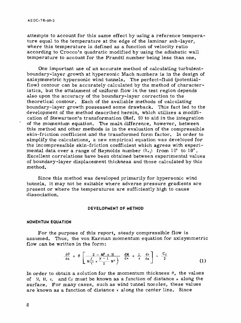
For the purpose of this report, steady compressible flow is assumed. Thus, the von Karman momentum equation for axisymmetric flow can be written in the form:
d 8 2 - M 1 + H - d M + L d r - - cf d s d s r d s ] - 2
In order to obtain a solution for the momentum thickness 8, the values of 1 1 , and Cr must be known as a function of distance s along the surface. For many cases, such a s wind tunnel nozzles, these values a r e known a s a function of distance x along the center line. Since

~ q . (1) may be written a s
When o is small, the assumption that sec o = 1 can be made with negligible consequences.
It can be recognized that Eq. (3) is a linear, f i rs t-order , ordinary differential equation of the form
which has the solution
Since P(x) and Q(X) a r e generally non-analytic functions of x , numerical methods must be used to evaluate the indicated integrations.
The solution of Eq. (3) is considerably simplified, however, through the use of the equations
and
which a r e obtained f rom Stewartson's transformation a s shown in Appendix A. By substituting Eq. ( 6 ) and (7) into Eq. (3), the equation
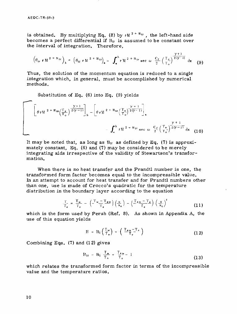
is obtained. By multiplying Eq. (8) by r M + , the left-hand side becomes a perfect differential i f Htr is assumed to be constant over the interval of integration. Therefore,
Thus, the solution of the momentum equation is reduced to a single integration which, in general, must be accomplished by numerical methods.
Substitution of Eq. (6) into Eq. (9) yields /
It may be noted that, a s long as Ilt, a s defined by Eq. (7 ) is approxi- mately constant, Eq. (6) and (7) may be considered to be merely integrating aids irrespective of the validity of Stewartson's transfor- mation.
When there is no heat transfer and the Prandtl number is one, the transformed form factor becomes equal to the incompressible value. In an attempt to account for heat transfer and for Prandtl numbers other than one, use is made of Crocco's quadratic for the temperature distribution in the boundary layer according to the equation
which is the form used by Persh (Ref. 8). As shown in Appendix A, the use of this equation yields
Combining Eqs. (7) and (1 2) gives
T Taw 1 = I + - - I
To To
which relates the transformed form factor in terms of the incompressible value and the temperature ratios.

For the evaluation of Eq. (1 ) for a particular problem, values of r, XI, a, and y a r e given a s functions of x . With the wall temperature given o r assumed a s a function of x, Ht, may be found by Eq. (13) in t e rms of Hi . Still remaining to be determined a r e C f and Hi, which a r e considered in subsequent sections.
DETERMINATION OF Cf
The compressible skin-friction coefficient Cf in Eq. (10) is a function of Mach number, Reynolds number, and heat t ransfer and is defined in t e rms of the shearing s t r e s s at the wall,
Ln the evaluation of C f , efforts a r e made to obtain empirical correlations with the incompressible value which is a function of Reynolds number based either on the momentum thickness o r distance,
The assumption has been made that there i s some reference point in the compressible boundary layer where the temperature and density a r e such that
where
and the values of p ' and p' a r e evaluated at the reference temperature. Therefore,
Cf - , I ' , C f ' ( I ' C f l = :.__ -- --.- - -
2 R e 2 1 . ' 2 (19)
since the pressure is assumed to be constant through the boundary layer.
It may be shown, however, that
T 3 F(Ro8) + +T G ( R x Y ) T '
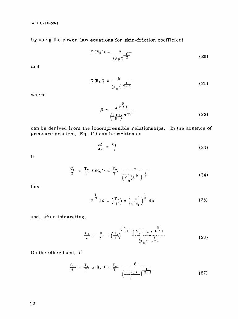
by using the power-law equations for skin-friction coefficient
and
where
can be derived f rom the incompressible relationships. In the absence of p ressu re gradient, Eq. (1) can be written a s
then
and, af ter integrating,
On the other hand, i f

then
and, af ter integrating,
It is obvious that Eq. (26) is not equal to Eq. (29), and therefore Eq. (24) and Eq. (27) cannot both be correct . Experimental correlation must be made to determine which equation gives the better resu l t s .
The determination of the proper value of reference tempera ture to be used must a l so depend upon experimental correlation. Eckert (Ref. 7) suggests the relation
'I" = 0.5 Tw + 0.22 Taw + 0.28 Te
which, if the recovery factor is equal to 0. 896, becomes
Sommer and Short (Ref. 5) suggest the relation
which, again i f the recovery factor is equal to 0. 896, becomes
Eckert ' s relation shows slightly grea ter effects of both heat t ransfer and Mach number than does that of Sommer and Short and appears to give slightly bet ter correlation with the meager amount of data which exis ts a t hypersonic Mach numbers. In order to take into account the effects of variable specific heat, Eckert suggests the use of a reference enthalpy
fo r evaluating the physical properties of the gas. Although the derivations described herein a r e developed f o r constant specific heat, this modification can be easily substituted throughout.

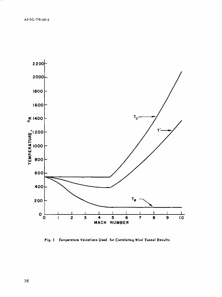
The correlation of theoretical resul ts with experimental data can be made by comparing the ratios of compressible skin-friction coefficients to the incompressible value at the same free-stream Reynolds number. Most of the experimental data have been obtained in wind tunnels. In the supersonic range up to a Mach number of about 5, stagnation temperatures a r e of the order of 100" F or 560" R while the static temperatures decrease with increasing Mach number until a value of about 100" R is reached. At higher Mach numbers, the stagnation temperature is increased to maintain the static temperature at about 100°R in order to avoid liquefaction of the constituents of the air. The temperature variation which is suggested for correlating wind tunnel resul ts is shown in Fig. 1 along with Ecker t l s reference temperature for the adiabatic wall condition. The temperature range is s o great that a simple power law for the variation of viscosity with temperature is not valid, and Sutherland's law must be used above 198. 7" R. Below this temperature, there is some meager evidence that the viscosity varies proportionally with the temperature (the curve is tangent to the Sutherland curve). Misleading resul ts can be obtained i f such factors a r e not taken into account for correlation over a wide range in Mach numbers.
A correlation of C f / C f i a s a function of Mach number is shown in Fig. 2. The experimental data were taken from Refs. 10 through 17 and a r e for approximately adiabatic wall conditions. The values of Cr,
used for the rat ios were obtained from the relation
0 .088 ( log H x i - 2.3686) C f . = --
1 ( log I t X i - 1 .5 ) '
which is developed in Appendix B. The values of C f were obtained from the relation
r 0 .088 ( log R, ' - 2.3686) C r = 2 T ' ( log R , ' - 1.5))
where
and R,, the free-stream Reynolds number, is the same a s R x i for this curve. The static and reference temperatures from Fig. 1 were used to obtain the ratio of C f . / C f , shown in Fig. 2. The good correlation shown indicates that Eq. (36) provides an adequate method of determining C r for use in Eq. (10). It should be noted that Eq. (36) is of the general form of Eq. (27) which therefore represents experimental resul ts better than Eq. (24) .

Much of the experimental data is available in t e r m s of I l o . The corresponding value of R , can be found f rom Eq. (36) in the same manner in which Eq. (29) was obtained f rom Eq. (27).
O.Ot-I clog 11,~'- 2.1686)
( l o g I{,' - 1 . ~ 1 ~
After integration
c - -
8 -
'I' 0.044 r: - - - 119 = -e_ ~. . - . 2 X 't x I ' ( log I I , ' - 1.sV
Therefore
R * = 1' -- 0.044 I{, '
P e ( l og R , ' - 1.5)
F r o m this equation, the determination of Iln i s straightforward when I < , ' i s given; however, when R o i s given, R,' must be found by some iterative method such a s Newton's. In a s imi lar manner.
Once R x ' and I l x l a r e found to satisfy Eqs. (40) and (41 ), C f and C r i can
be found f rom Eqs. (36) and (35) for R n = 110~ and a new ra t io of (:f ' C f ,
can be determined. Such a rat io is shown in Fig. 3 along with experimental data from Refs. 10, 11, 18, 19, and 20. Again, good correlation i s shown, indicating that Eq. (36) is satisfactory for the determination of C f .
DETERMINATION OF Hi
As shown previously by Eq. (13), the transformed form factor can be expressed in t e rms of the incompressible, adiabatic form factor and temperature rat ios . It is fur ther shown in Appendix B that I l i i s related to C f , by
and i s , therefore, a function of the incompressible Reynolds number. Thus, there remains the problem of determining the relation between the compressible and incompressible Reynolds number.
In the transformation of Eq. (3) into Eq. (8) by means of Eq. (6) and (7), no transformation of s was involved. However, Eq. (8) can be written a s

where U, is the transformed velocity (Appendix A) and the transformation dx/dX must be defined. For incompressible flow, the momentum equation can be written a s
d o i Oi d u e ; - + - e i d Cf ( 2 + I l i ) + - -L = 2
d x i sec o U e i d x i r d x i 2
with fluid properties po and po evaluated at To. Comparison of these equations indicates that the transformed flow may be considered in- compressible if
where Cf is obtained a s a function of Reynolds number based on x and C f i is obtained a s a function of Rx = po Ue X /po .
The original Stewartson's transformation used the relation
d X 2 ( y - 1 ) = ( for y = 1.4
dr
Culick and Hill (Ref. 21) using the stagnation temperature a s a reference temperature obtained the relation
-- K - 1 Y + l +- 1
2 0 ' - 1 ) N 4 - - d X N
d x for y = 1.4
Mager (Ref. 22) using a s t i l l different approach obtained the relation
d X P e T 2 ' ~ - 1 ) - = T '
dx Lo(<) = ( ) for y = 1.4
which reduces to Stewartson's transformation if the viscosity is assumed proportional to the temperature.
If Eqs. (35) and (36) a r e substituted into Eq. (45), the resul t i s , since R x = R x i ,
, - --- {I, - (log R g - 2.3686) 2 0 ' - 1 ) 're (log I { , ' - 2 .3686) p '
---- d R X = (%) -- - - d R x ' (49) p, U, (log H X - 1.5)' ' r ' ( i ~ g ~ . ' - i . s ) ' p ' ~ e

A E D C - T R-59-3
which, af ter integrating, yields
Since
Eq. (50) reduces to
R x -. - - - - I L R x ' - - -
(log R X - 1.5)' p ( log R, '- 1.5)
which r e l a t e s the incompressible Reynolds number t o the re fe rence Reynolds number. Eq. (51) cannot be solved direct ly fo r Ilm, but the use of Newton's approximation with R x = ( / L : I ~ ~ ) I I ~ ' a s the f i r s t approximation yields a s a second approximation
which is sufficiently accurate t o determine (:fi f r om Eq. (35). This
value of C f , is then used in Eq. (42) to determine I l i , af te r which l l t , can
be found f r o m Eq. (13) f o r use i n integrating Eq. (10).
APPI-ICATION TO AXISYMMETRIC TUNNELS
In the application of Eq. (10) to calculate the boundary l aye r growth of an ax isymmetr ic wind tunnel, the calculations a r e usually begun a t the throat where the Mach number is unity. Equation (10) can thus be wri t ten
Y + 1 T Z(Y-1)
= 0- (*)
In many cases , the momentum thickness a t the throat 8* can be assumed t o be equal t o z e r o without appreciably affecting the values calculated nea r the end of the nozzle.
The Reynolds number a t the throat must be based upon a value of x
which is other than ze ro i n o rde r to s t a r t with a finite value of Cr. A useful approximation for this init ial value of X * can be obtained in the manner suggested by Sibulkin in Ref. 23. The velocity gradient a t the throat is obtained in t e r m s of the rad ius of curvature a t the throat:
It i s then assumed that the velocity gradient is constant f rom ze ro to the throat s o that
Therefore ,
The Reynolds number a t each point along the nozzle is thus based upon a value of x equal to X* plus the distance f rom the throat t o the point. In general , the distance s along the nozzle contour m a y be assumed to be equal t o the distance x along the axis f o r the purpose of determining the Reynolds number.
The above approximation can a l so be used to es t imate the momentum thickness a t the throat with the additional assumption that the values of the re fe rence tempera ture and the re fe rence Reynolds number a r e constant and equal to the values a t the throat. Equation (10) may then b e writ ten
Y + l Y + l + 1 2 + H t r d u e /dM
d u e l d x dhl
(57)
Since

and
thus, after substitution and rearranging,
or , when y = 1.4,
0.0694(10g R,. '- 2.3686) To o* =
d M (log uX. '- 1.5)~ T* ' (1 + 0 . 2 ~ ~ ) '
The integration indicated in Eq. (61) can be performed analytically for values of 11 t, which a r e odd multiples of 0. 5. F o r intermediate values, the integration must be performed numerically. The resul ts of such integrations a r e shown in Fig. 4,
F o r conical nozzles in which radial flow can be assumed, the Mach number is constant over each spherical segment of a r e a 2n 1 / ( 1 + cos o),
Since the throat a r e a is nr*',
f rom which

Then, s ince dr/dx = tan o
5 - 3 ) '
1 + cos a - ~ ( 1 + ~ 1 ) 4 ( y - 1 ) c 0 t a d x = L d F 2 y + l d M (6 5)
Substituting Eqs. (63) and (65) into Eq. (10) yields
r* ( 1 + cos o) cac + (66)
As before, if the re fe rence tempera ture and re fe rence Reynolds number can be assumed to be constant,
and, if = 1.4,
0.00637 (log H, ' - 2.3686) To r * Cot 5 +
(log R , ' - 1.5)' T ' (68)
The integration indicated in Eq. (68) can be per formed analytically when Fltr i s an integer and numerically when Fit, is not an integer. The r e su l t s of such integrations a r e shown in Fig. 5 where the integration in each case is performed, for convenience, over the interval f r o m 1 t o h l . Obviously,

F o r the general case of conical and contoured nozzles, the reference temperature and Reynolds number a r e not constant, and f o r the con- toured nozzle the radius is not an analytic function of the Mach number. Equation (53) must therefore be used downstream of the throat while Eq. (60) or (61) can be used to estimate the value a t the throat. In many cases, the variation of R x over the length of the nozzle is smal l enough that a constant average value of 1 J i can be used and the computa- tions involved can thereby be simplified.
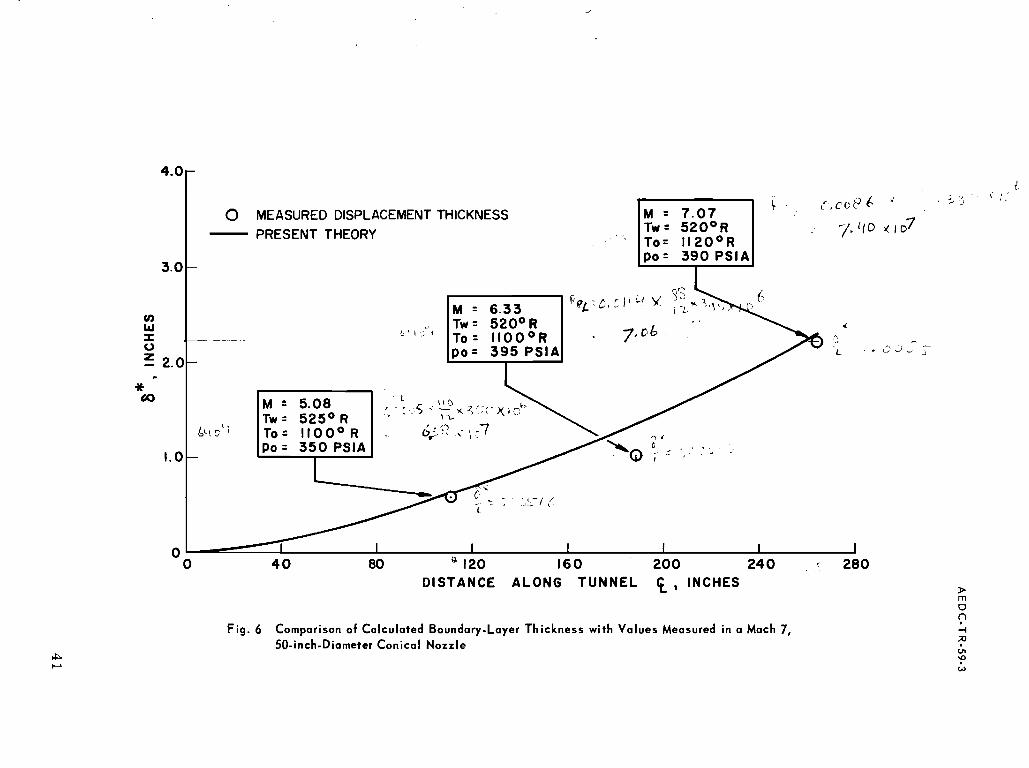
Values of boundary-layer displacement thickness calculated by the method described a r e compared with experimental values in Figs. 6 and 7 for Mach 7 and 8 conical nozzles and in Fig. 8 for a Mach 8 contoured nozzle. The experimental data were obtained in the 50-inch- diameter nozzles of the Gas Dynamics Facility. The agreement shown is considered to be extremely good.
CONCLUDING REMARKS
A method has been developed for calculating the growth of a turbulent boundary layer at hypersonic Mach numbers. Excellent agreement with experimental resul ts from axisymmetric nozzles has been obtained through the application of this method. The basis for the calculations is Eq. (10) wherein the compressible skin-friction coefficient is obtained from Eq. (36), and the transformed form factor is given by Eq. (1 3) in which the incompressible form factor is related by Eq. (42) to the incompressible skin-friction coefficient evaluated at the incompressible Reynolds number given by Eq. (52).
APPENDIX A
STEWARTSON'S 'TRANSFORMATION
In the Stewartson's t ransformat ion, as given i n Ref. 9, the distance no rma l to the su r f ace is t ransformed by the re la t ion
and the velocity para l le l to the su r f ace is t ransformed by the re la t ion
U = " a" (A-2)
External of the boundary l aye r
s o that
The definition of boundary-layer momentum thickness is
where A is the value of y where both velocity and t empera tu re r e a c h the i r f r e e - s t r e a m values. Substitution of Eqs. (A-1) and (A-4) into Eq. (A-5) yields
The t ransformed momentum thickness is defined as
s o that

Y+ 1 Y + 1 Y - 1 Y ) 20'-1) = etr (To)21~-I) 6 = e,, (1 + -
2
It m a y be noted that Eq. (A-7) has the form fo r incompressible flow, although the shape of the velocity profile is distorted by the t r a n s - format ion (see Ref. 24).
In a s imi l a r manner, the boundary-layer displacement thickness is defined by the equation
Since the p r e s s u r e is assumed to be constant through the boundary layer , Eq. (A-10) may be writ ten a s
The s ta t ic t empera ture distribution through the boundary l aye r may be e x p r e s s e d b y
(A- 1 2)
where T, is the local stagnatior, t empera ture corresponding to the local s ta t ic t empera ture 'I'. Substituting Eqs. (A-1), (A-4), and (A-12) into Eq. (A-11) yields
where, by definition
(A- 1 4)
(A- 15)
When T, is cons tan t and equa l t o To, Eq . (A-15) h a s t h e f o r m f o r i n - c o m p r e s s i b l e flow.
Divis ion of Eq. ( 8 - 1 4) b y Eq. (A-8) y i e lds
(A- 16 )
Equa t ions ( 8 - 9 ) a n d (A-17) w e r e u s e d t o t r a n s f o r m Eq. ( 3 ) . Equat ion (A-1 5 ) m a y b e w r i t t e n as
s o t h a t
H , , = --
w h e r e
(A- 1 8 )
(A- 20)
In o r d e r t o eva lua te Eq. (A-19), u s e is m a d e of C r o c c o f s q u a d r a t i c t e m p e r a t u r e d i s t r ibu t ion , w r i t t e n as i n Ref. 8,
(A- 21 )
which a s s u m e s t h a t t h e t h e r m a l boundary l a y e r h a s t h e s a m e t h i c k n e s s as the ve loc i ty b o u n d a r y l a y e r . T h i s would o c c u r only if t h e P r a n d t l n u m b e r i s unity. However , Eq. (A-21 ) p a r t i a l l y a c c o u n t s f o r P r a n d t l n u m b e r s o t h e r t h a n uni ty th rough the u s e of the ad iaba t i c w a l l t e m p e r a - t u r e i n s t e a d of t he s t agna t ion t e m p e r a t u r e . Subs t i tu t ion of Eq. (A- 21 ) i n t o Eq. (A-1 1), a long with E q s . (A-1) a n d (A-4) y i e lds

Division of Eq. (A-23) by (A-8) yields
Equations (A-24) and (A-17) may be combined s o that
(A- 23)
(A- 24)
(A- 25)
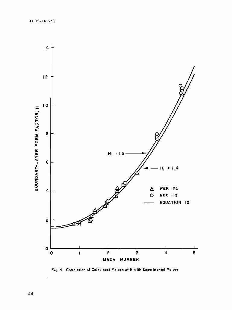
The variation of 11 according to Eq. (A-24) a s a function of Mach number is compared in Fig. 9 with experimental resul ts from Refs. 10 and 25 and in Fig. 10 with the tabulated resul ts from Ref. 26. The correlation is considered to be very good and justifies the derivation described.

A E D C - T R-59-3
APPENDIX B
INCOMPRESSIBLE SKIN-FRICTION COEFFICIENTS
A great many empirical equations have been developed for the variation of the local and mean skin-friction coefficients with Reynolds number for incompressible flow. Probably the most simple to use a r e the power-law equations
where
F o r a limited range of Reynolds numbers, values of a , P , and U can be considered to be constant; but, for a la rge range of Reynolds numbers, their values must also be functions of the Reynolds number.
Locke (Ref. 27) investigated a number of the empirical equations and found that Schoenherr ' s equation
gave a good correlation with a very la rge amount of experimental data over the wide range of Reynolds numbers from l o 5 to 10 ' . Other forms of this equation a r e
-- - log ( 2 Ro,) \Ti

AEDC-TR-59-3
and
C f i = ( 0.242 1'
log ( 2 R O , ) [ log ( 2 R O , ) + 0.8686 I (B-7)
Although Schoenherr ' s equations co r r e l a t e well with experimental resu l t s , they a r e difficult to use because neither Cr, o r C F , can b e found
direct ly a s a function of R X i . Tables can be constructed for use when the
computing is done manually; however, m o r e direct equations a r e des i red fo r use with automatic computers. Any se t of equations mus t sat isfy the relationship
After an investigation of s eve ra l types of equations, the equations
C F . = 0.088
( log H x i - 1.5)'
and
0.088 ( l o g R , , - 2.3686) C f . =
( l o g R x i - 1.5)~
were found to cor re la te with experimental data a s well a s Schoenherr ' s equations over the range of Reynolds numbers f rom 10' to l o 9 . A comparison of values of C F , calculated f r o m Eq. (B-10) with those f r o m
Eq. (B-5) i s shown in Fig. 11 together with the "ideal" values f rom Ref. 28 and 29. A s imi l a r comparison of values of Cr, is shown in
Fig. 12 together with experimental values of Dhawan (Ref. 30), Schultz- Grunow (Ref. 31), and Kempf (Ref. 32). These data a r e recognized a s being among the mos t accurately determined values available. A fur ther comparison of R e i a s a function of R x i is made in Fig. 13 with
the experimental values of Wieghardt (Ref. 33). All of these com- par isons indicate the validity of Eqs. (B-10) and (B-11).
A cr i t i ca l examination of the curve of Eq. (B-10) shows that i t c r o s s e s Schoenherr ' s curve a t a Reynolds number of about lo ' and again a t about 5 x lo ' . Moreover, i t goes to infinity when log R X i = 1. 5 o r
n x i = 3 2. Fur thermore , the curve of Eq. (B- 11) has ze ro slope when

log R x i = 2. 3686 o r R x i = 234. Both of these conditions a r e well below
the range for turbulent boundary layers and are , therefore, of academic interest only. The values of the constants, 0. 088 and 1. 5, could have been chosen to agree better with Colesf values but the experimental values do not warrant such a selection.
The incompressible form factor H i is a lso a function of Reynolds number and is shown in Ref. 29 to be related to the skin-friction coefficient in the manner,
H i = 1
1 - 7 4- (B- 12)
where the constant 7 (although different from that of Ref. 29) is chosen for correlation with experimental data. Such correlations a r e shown in Figs. 14 and 15. Again the correlations a r e quite satisfactory.
F o r comparative purposes, values of C F i , Cr , , R e i , and Fli a r e
listed in Table 1 for various values of Rxi from 10' to 10'. Also
listed a r e the values of N obtained from Eq. (B-3) which show that the use of Eqs. (B-1) and (B-2) must be limited to small ranges of Reynolds number.

REFERENCES
1. Granville, Pau l S. "A Method for the Calculation of the Turbulent Boundary Layer i n a P r e s s u r e Gradient. Rep. 75 2, Navy Dept. , The David W. Taylor Model Basin (Washington, D. C. ), May 1951.
2. Tetervin, Neal and Lin, Chia Chiao. "A General Integral F o r m of the Boundary-Layer Equation for Incompressible Flow with a n Application t o the Calculation of the Separation Point of Turbulent Boundary Layers . " NACA Rept. 1046, 1951.
3. Tucker, Maurice. "Approximate Calculation of Turbulent Boundary-Layer Development i n Compressible Flow, " NACA TN 2337, April 1951.
1 1 4. Bar tz , D. R. An Approximate Solution of Compress ib le Turbulent Boundary-Layer Developme nt and Convective Heat T r a n s f e r i n Convergent -Divergent Nozzles. ' I J P L CIT, P r o g r e s s Report No. 20-234, July 1954.
5. Sommer, Simon C. , and Short, Ba rba ra J. "Free- light Measurements of Turbulent-Boundary-Layer Skin Fr ic t ion in the P re sence of Severe Aerodynamic Heating a t Mach Numbers f rom 2.8 to 7.0. ' I NACA TN 3391, March 1955.
6. Tendeland, Thorval. " ~ f f e c t s of Mach Number and Wall- Tempera ture Ratio on Turbulent Heat T rans fe r a t Mach Numbers f r o m 3 to 5." NACA TN 4236, April 1958.
I I 7. Ecker t , E. R. G. Survey on Heat T rans fe r a t High Speeds. 1 1
WADC Technical Report 54-70, April 1954.
8. P e r s h , J e rome . "A Theoret ical Investigation of Turbulent Boundary-Layer Flow with Heat T rans fe r a t Supersonic and Hypersonic Speeds. NAVORD Report 3854, May 1955.
I I 9. Reshotko, El i and Tucker , Maurice. Approximate Calculation of the Compressible Turbulent Boundary Layer with Heat T r a n s f e r and Arb i t r a ry P r e s s u r e Gradient. NACA TN 4154, December 1957.
I I 10. Coles, Donald. Measurements in the Boundary Laye r on a Smooth F l a t P la te i n Supersonic Flow, 111. Measurements i n a F la t -P la te Boundary Layer a t the J e t Propuls ion Laboratory.
I I
J P L Report No. 20-71, June 1953.
11. Lobb, L. K., Winkler, E. M, and Pe r sh , J e rome . "NOL Hypersonic Tunnel No. 4 Resul ts VII: Experimental Investiga- tion of Turbulent Boundary Laye r s i n Hypersonic Flow. I I
NAVORD Report No. 3880, ARR 26 2, March 1955.

1 1 12. Chapman, Dean R. and Kester , Rober t H. Measurements of Turbulent Skin F r i c t i on on Cyl inders in Axial Flow a t Subsonic
I I and Supersonic Velocit ies. P a p e r p resen ted a t 21st Meeting, I. A. S. , New York, N. Y., J anua ry 26-29, 1953 (P rep r in t No. 391).
I I 13. Fallis, W. B. Heat T r a n s f e r i n the Transi t ional and Turbulent Boundary L a y e r s on F l a t P l a t e a t Supersonic Speeds. " UTIA Rep 19, Universi ty of Toronto, May 195 2.
1 1 14. Pappas , C. C. Measurement of Heat T r a n s f e r in the Turbulent Boundary Laye r on a F l a t P l a t e i n Supersonic Flow, and Comparison with Skin-Fr ic t ion Results . " NACA TN 3222, June 1954.
15. Humble, L. V., Lowdermilk, W. H., and Desman, L. G . I I Measurements of Average Hea t -Transfe r and Fr ic t ion Coefficients f o r Subsonic Flow of Air i n Smooth Tubes a t High Surface and Fluid Tempera tu r e s . " NACA Report 1020, 1951.
16. De Coursin, D. G . , Bradfield, W. S., and Sheppard, J. J. I I Measurement of Turbulent Heat T r a n s f e r on Bodies of Revolution a t Supersonic Speed. " JAS 23, March 1956, pp 272-3. Also WADC Report 53-379, F e b r u a r y 1954.
1 1 17. Monaghan, R. J. and Cooke, J. R. The Measurement of Heat T r a n s f e r and Skin Fr ic t ion a t Supersonic Speeds. " P a r t 111 I I Measurements of Overal l Heat T r a n s f e r and of the Associated Boundary L a y e r s on a F l a t P l a t e a t M i = 2.43. l1 Tech. Note AERO 21 29, Br i t i sh R. A. E . , December 1951.
I I 18. Hill, F. K. Boundary-Layer Measurements i n Hypersonic Flow. I I
JAS 23, J anua ry 1956, pp 35 - 42. 1 1 19. Korkegi, R. H. Trans i t ion Studies and Skin-Frict ion Measure -
men t s on an Insulated F l a t P l a t e a t a Mach Number of 5.8. 1 1
JAS 23, F e b r u a r y 1956, pp 97 - 107, 192. I I 20. Brinich, P. F. , and Diaconis, N. S. Boundary-Layer Development
and Skin Fr ic t ion a t Mach Number 3.05. " NACA TN 2742, Ju ly 1952.
21. Culick, F r e d E. C. , and Hill, Jacques A. F. "A Turbulent Analog of the Stewartson - Illingworth Transformat ion. " JAS 25, April 1958, pp 259 - 26 2.
I I 22. Mager, Artur . Transformat ion of the Compress ib le Turbulent Boundary Laye r . " JAS 25, May 1958, pp 305 - 311.
23. Sibulkin, Merwin. eat T r a n s f e r to an Incompress ible Turbulent Boundary Laye r and Est imat ion of Hea t -Transfe r Coefficients a t Supersonic Nozzle Throats . " J P L Report No. 20-78, Ju ly 1954.
Reshotko, E l i and Tucker , Maurice. " ~ f f e c t s of a Discontinuity on a Turbulent Boundary-Layer-Thickness P a r a m e t e r with Application to Shock-Induced Separation. I ' NACA TN 3454, May 1955.
I I Baron, Judson R. Analytic Design of a Fami ly of Supersonic Nozzles by the F r i e d r i c h s Method. " WADC TR 54-279, June 1954.
11 Tabulation of Compressible Turbulent-Boundary-Layer P a r a m - e t e r s . I ' NAVORD Report No. 428 2, May 1956.
11 Locke, F. W. S. , Jr. Navaer Recommended Definition of I I Turbulent Fr ic t ion i n Incompressible Fluids. Bureau of
Aeronautics, Navy Dept., DR Report No. 1415, June 1952. I I Smith, Donald W. and Walker, John H. Skin Fr ic t ion Measure-
ments i n Incompressible Flow. " NACA TN 4231, March 1958. I f Coles, Donald. Measurements i n the Boundary Layer on a
Smooth F l a t P la te i n Supersonic Flow, I. The P rob lem of the Turbulent Boundary Layer . I ' J P L Report No. 20-69, June 1953.
I I Dhawan, Satish. Direct Measurements of Skin Fr ic t ion. " NACA Report No. 11 21, 1953 (Supersedes NACA TN 2567).
I I Schultz-Grunow, F. New Fric t ional Resis tance Law f o r Smooth P la tes . I t NACA TM 986, 1940.
I I Kempf, von Gunther. Neue Ergebnisse d e r Widerstandsforschung. I 1
Werft, Reederei , Hafen, Vol. 10, No. 11, pp 234- 239; No. 1 2 pp 247-253, 1929.
Wieghardt, K. " ~ u m Reibungswiderstand r auhe r Platten. I ' ZWB, KWI, U and M 661 2, Sept. 1944. See a l so " ~ l b e r die turbulente s t r6mung i m Rohr und l i n g s e iner Pla t te . I ' ZAMM, Vol. 24, No. 5 16, pp 294-296, 1944.
11 Hama, F. R. The Turbulent Boundary Layer Along a F l a t P la te , I and 11. " (in Japanese) Reports of the Institute of Science and Technology, Tokyo Imperia l University, Vol. I, No. 1, pp 13 - 16. No. 3 - 4, pp 49 - 50, 1947.

TABLE 1
INCOMPRESSIBLE SKIN FRICTION VALUES
I I I I I I I I I I 0 I 2 3 4 5 6 7 8 9 10
MACH NUMBER
Fig. 1 Temperature Variations Used for Correlating Wind funnel Results

0 C H A P M A N A N D K E S T E R 6 . 0 < ~ x ~ l 0 - ~ < 1 6 . 0 h P A P P A S I . o < R ~ x I o - ~ < ~ ~ . ~ a HUMBLE, L O W D E R M I L K , A N D D E S M A N 1 . O<RX ~10-~<10.0
1.0 0 C O L E S 3 . 0 < R x x 1 0 - ~ < 1 0 . 0 4.0 <Rx ~ 1 0 - ~ < 9 . 4 1 . 2 < f ? x ~ l 0 - ~ < 6 . 0
0 D E C O U R S I N , B R A D F I E L D , A N D S H E P P A R D R X = ~ . O X I O M O N 4 G H A N A N D C O O K € Rx= 1 . 0 ~ 1 0
0:e
0.6 .- *
K *
0 0;4
0; 2
M A C H N U M B E R a n
Fig. 2 correlation of Calculated Ratios, C J C ~ , , with Experimental Values Based upon R.

0 HILL LOBB, W I N K L E R , AND PERSH
V BRINICH AND DIACONIS [1\ KORKEGI
MONAGHAN AND COOK€ 0 COLES
i 1 I I I I 1 I I 1
2 3 4 5 6 7 8 9 to I MACH NUMBER
Fig. 3 Correlation of Calculated Ratios, Cf/Cf, , with Experimental Values Based upon Ro

Fig . 4 Values of Integral Used in Calcu4ating Boundary-Layer Thickness a t the
Throat of an Axisymmetric Nozz le

f rcc :6 '6 0 MEASURED DISPLACEMENT THICKNESS - PRESENT THEORY Tw = 5 2 0 ° R y.l/O
P O = 390 P S l A 3.0
M 5.08 I . Tw= 5 2 S 0 R LLI : T O = l l O O O R .
Po = 350 P S l A .o -
n I 1 - 0 40 8 0 " 120 16 0 200 24 0 280
D I S T A N C E A L O N G T U N N E L 6 , INCHES
Fig. 6 Comparison of Calculated Boundary-Layer Thickness with Values Measured in a Mach 7, 50-inch-Diameter Conical Nozzle

A REF. 2 5
0 REF. 10
- EQUATION 12
0 I 2 3 4 5 MACH NUMBER
Fig. 9 Correlation of Calculated Values of H with Experimental Values
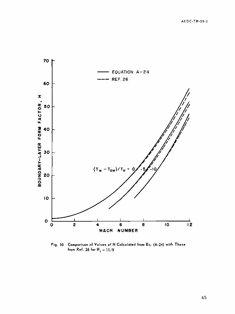
- EQUATION A - 24 --I REF. 26
M A C H NUMBER
Fig. 10 Comparison of Values of H Calculated from Eq. (A-24) with Those
from Ref. 26 for H i = 11/9

li
li
ri
W
WW
a
aa

Fig. 13 Comparison of Various Equations Relating R with R, 'i i

D REF. 3 4 SERIES T 0 REF. 3 4 SERIES E 0 REF. 3 3 . 3 3 . 0 METERS/SEC 0 REF. 3 3 . 1 7 . 6 METERS/SEC
F ig . 14 Comparison of Various Equations Relating Hi with R 0 ,
