a method for development and validation of multi-agent ... · of multi-agent systems using accurate...
TRANSCRIPT

A Method for Development and Validation
of Multi-Agent Systems Using Accurate
Communication Network Modelling
by
Fidelis Perkonigg
Submitted in accordance with the requirements for
the degree of Doctor of Philosophy
Imperial College London
Department of Mechanical Engineering
2014
Declaration of Originality
I Fidelis Perkonigg hereby declare that this dissertation and work described in it are
my own work and that they not contain material that has already been used to any
substantial extent for a comparable purpose.
Copyright Declaration
The copyright of this thesis rests with the author and is made available under a Creative
Commons Attribution Non-Commercial No Derivatives licence. Researchers are free to
copy, distribute or transmit the thesis on the condition that they attribute it, that they
do not use it for commercial purposes and that they do not alter, transform or build
upon it. For any reuse or redistribution, researchers must make clear to others the
licence terms of this work.
2
Abstract
There has been a considerable amount of research on multi-agent system (MAS) tech-
nologies for a wide variety of industrial applications. One application domain is the power
industry, for which multi-agent systems are widely suggested as a promising method for
the realisation of highly distributed, flexible, fault tolerant management and control ap-
plications. Multi-agent systems make extensive use of digital communication, which can
significantly influence the overall system performance.
However, no general solutions have been proposed for the difficult tasks of multi-
agent system development and validation that would fully account for the underlying
communication network performance, before it is first deployed on the target system.
This work proposes a new method for this purpose and presents a novel platform that
consists of a federation of a standardised multi-agent system development framework
(JADE) and an industry standard network simulator (OPNET Modeler). It was realized
through generic extensions of the JADE framework to provide discrete event scheduling
capabilities, while the OPNET Modeler was extended to provide a generic method of
relating network nodes with agents running in JADE. The federation adheres to the High
Level Architecture standard. The multi-agent systems analysed using this platform may
be deployed on the target system without manual modifications.
An example of a time-critical, agent-based protection system for the Smart Grid is
presented and its performance analysed with respect to candidate agent behaviours and
different communication scenarios. The results clearly show that the feasibility of the
multi-agent system critically depends on the application design as well as the commu-
nication infrastructure. The developed multi-agent system was shown to be directly
deployable on target hardware, which proves that the proposed method not only sup-
ports analysis through simulation but also subsequent deployment.
The new platform can be used to rapidly develop a wide range of agent-based appli-
cations and validate them for different communication technologies before deployment.
Acknowledgements
First, I would like to acknowledge the financial support from the Energy Programme
which is an RCUK cross-council initiative led by EPSRC and contributed to by ESRC,
NERC, BBSRC and STFC. I would also like to acknowledge the OPNET University
Program, which provided a free research license for the network simulator that was used
in this research. Furthermore, I would like to thank my supervisor Mike Ristic for all
his help and advice, especially in giving feedback on my written work. I have had the
pleasure of getting to know my colleagues Djordje, Enrico, and Francesca. I enjoyed
their company and the stimulating discussions on professional and personal subjects.
Also, I would like to extend my thanks to the regular players of the Imperial Badminton
club with whom we spent great moments on and off the court. I wish them all the best
for their future and I hope we will stay in touch. And last but not least, I would like to
thank my family, Christine, Wilhelm, Rebecca, and Sofia for all their support they have
ever given me. I am truly grateful to them.
4
Contents
1 Introduction 14
1.1 Motivation . . . . . . . . . . . . . . . . . . . . . . . . . . . . . . . . . . . 14
1.2 Overall Aims . . . . . . . . . . . . . . . . . . . . . . . . . . . . . . . . . . 15
1.3 Specific Objectives . . . . . . . . . . . . . . . . . . . . . . . . . . . . . . . 16
1.4 Challenges . . . . . . . . . . . . . . . . . . . . . . . . . . . . . . . . . . . . 17
1.5 Overview of Contributions . . . . . . . . . . . . . . . . . . . . . . . . . . . 18
1.6 Thesis Structure . . . . . . . . . . . . . . . . . . . . . . . . . . . . . . . . 19
2 Previous Research and Background 20
2.1 Multi-Agent Systems (MAS) . . . . . . . . . . . . . . . . . . . . . . . . . 20
2.2 Smart Grid . . . . . . . . . . . . . . . . . . . . . . . . . . . . . . . . . . . 22
2.2.1 Types and Requirements of Applications . . . . . . . . . . . . . . . 24
2.2.2 Communication Technologies . . . . . . . . . . . . . . . . . . . . . 26
2.3 System Modelling . . . . . . . . . . . . . . . . . . . . . . . . . . . . . . . . 30
2.3.1 Simulation . . . . . . . . . . . . . . . . . . . . . . . . . . . . . . . 31
2.3.2 Computer Network Simulation . . . . . . . . . . . . . . . . . . . . 33
2.4 Previous Approaches to MAS Development and Validation . . . . . . . . . 34
2.4.1 Development Without Communication Network Validation . . . . 34
2.4.2 Independent MAS Development and Communication Analysis . . . 36
2.4.3 Development and Analysis Through Communication Network Mod-
elling . . . . . . . . . . . . . . . . . . . . . . . . . . . . . . . . . . 37
2.5 Federations . . . . . . . . . . . . . . . . . . . . . . . . . . . . . . . . . . . 39
2.6 Summary . . . . . . . . . . . . . . . . . . . . . . . . . . . . . . . . . . . . 41
3 Co-Simulation Platform Design and Architecture 42
3.1 Introduction . . . . . . . . . . . . . . . . . . . . . . . . . . . . . . . . . . . 42
3.2 Architecture Overview . . . . . . . . . . . . . . . . . . . . . . . . . . . . . 42
5
Contents
3.3 Runtime Infrastructure . . . . . . . . . . . . . . . . . . . . . . . . . . . . . 45
3.3.1 Distributed Simulation Modelling Architecture . . . . . . . . . . . 45
3.3.2 The High-Level Architecture . . . . . . . . . . . . . . . . . . . . . 45
3.4 Extensions to Multi-Agent Systems . . . . . . . . . . . . . . . . . . . . . . 47
3.4.1 Agent Execution . . . . . . . . . . . . . . . . . . . . . . . . . . . . 47
3.4.2 Agent Message Exchange . . . . . . . . . . . . . . . . . . . . . . . 54
3.4.3 Communication Between Agent System and RTI . . . . . . . . . . 56
3.4.4 Federation Object Model (FOM) . . . . . . . . . . . . . . . . . . . 57
3.5 Extensions to Communication Network Simulators . . . . . . . . . . . . . 58
3.5.1 Synchronisation and RTI Communication . . . . . . . . . . . . . . 58
3.5.2 Generic Agent Application . . . . . . . . . . . . . . . . . . . . . . 61
3.6 Simulation Execution and Time Management . . . . . . . . . . . . . . . . 63
3.7 Summary . . . . . . . . . . . . . . . . . . . . . . . . . . . . . . . . . . . . 68
4 MAC-Sim Platform Implementation 69
4.1 Introduction . . . . . . . . . . . . . . . . . . . . . . . . . . . . . . . . . . . 69
4.2 Platform Overview . . . . . . . . . . . . . . . . . . . . . . . . . . . . . . . 69
4.3 Runtime Environment (RTI) . . . . . . . . . . . . . . . . . . . . . . . . . 70
4.4 Java Agent DEvelopment Integration . . . . . . . . . . . . . . . . . . . . . 71
4.4.1 Development in JADE . . . . . . . . . . . . . . . . . . . . . . . . . 72
4.4.2 Discrete-Event Simulation Extension . . . . . . . . . . . . . . . . . 75
4.4.3 The Federated Agent (FedAgent) . . . . . . . . . . . . . . . . . . . 76
4.4.4 The RTI Agent . . . . . . . . . . . . . . . . . . . . . . . . . . . . . 79
4.5 OPNET Modeler Integration . . . . . . . . . . . . . . . . . . . . . . . . . 82
4.5.1 Network Modelling using OPNET Modeler . . . . . . . . . . . . . 82
4.5.2 Extended OPNET Modeler . . . . . . . . . . . . . . . . . . . . . . 84
4.5.3 HLA Interface . . . . . . . . . . . . . . . . . . . . . . . . . . . . . 84
4.5.4 Generic Agent Model . . . . . . . . . . . . . . . . . . . . . . . . . 85
4.6 Federation Execution Details (FED) File . . . . . . . . . . . . . . . . . . . 93
4.7 Performance Considerations . . . . . . . . . . . . . . . . . . . . . . . . . . 95
4.7.1 Computational Complexities . . . . . . . . . . . . . . . . . . . . . 95
4.8 Summary . . . . . . . . . . . . . . . . . . . . . . . . . . . . . . . . . . . . 96
6
Contents
5 Agent-Based Remote Backup Relay Supervision Case Study 98
5.1 Introduction . . . . . . . . . . . . . . . . . . . . . . . . . . . . . . . . . . . 98
5.2 Transmission System Protection . . . . . . . . . . . . . . . . . . . . . . . 98
5.3 Agent-Based Supervision Scheme . . . . . . . . . . . . . . . . . . . . . . . 100
5.4 Multi-Agent System Implementation . . . . . . . . . . . . . . . . . . . . . 102
5.4.1 Client-Server Approach . . . . . . . . . . . . . . . . . . . . . . . . 102
5.4.2 Peer-to-Peer Approach . . . . . . . . . . . . . . . . . . . . . . . . . 103
5.4.3 Relay Agent Implementation . . . . . . . . . . . . . . . . . . . . . 104
5.4.4 Domain Master Agent Implementation . . . . . . . . . . . . . . . . 106
5.4.5 Agent Messages . . . . . . . . . . . . . . . . . . . . . . . . . . . . . 108
5.5 Communication Network Models . . . . . . . . . . . . . . . . . . . . . . . 109
5.5.1 Network Infrastructure . . . . . . . . . . . . . . . . . . . . . . . . . 110
5.5.2 Network Scenarios . . . . . . . . . . . . . . . . . . . . . . . . . . . 110
5.6 Simulation Setup and Execution . . . . . . . . . . . . . . . . . . . . . . . 115
5.7 Results . . . . . . . . . . . . . . . . . . . . . . . . . . . . . . . . . . . . . . 117
5.7.1 Overall MAS Performance . . . . . . . . . . . . . . . . . . . . . . . 118
5.7.2 Effect of Different Message Sizes . . . . . . . . . . . . . . . . . . . 121
5.7.3 Additional Links to Improve Performance . . . . . . . . . . . . . . 121
5.7.4 Impact of Link Outages . . . . . . . . . . . . . . . . . . . . . . . . 124
5.7.5 Optimal Placement of the Domain Master Agent . . . . . . . . . . 127
5.7.6 Impact of Peer Selection . . . . . . . . . . . . . . . . . . . . . . . . 127
5.8 Simulation Requirements . . . . . . . . . . . . . . . . . . . . . . . . . . . 129
5.8.1 Simulation Execution Times . . . . . . . . . . . . . . . . . . . . . . 129
5.8.2 Memory Requirements . . . . . . . . . . . . . . . . . . . . . . . . . 131
5.8.3 Storage Requirements . . . . . . . . . . . . . . . . . . . . . . . . . 131
5.9 Agent Model Deployment . . . . . . . . . . . . . . . . . . . . . . . . . . . 132
5.9.1 Test Setup . . . . . . . . . . . . . . . . . . . . . . . . . . . . . . . 132
5.9.2 Modifications of Deployed Agent Code . . . . . . . . . . . . . . . . 134
5.9.3 General Requirements for Deployment . . . . . . . . . . . . . . . . 136
5.10 Summary . . . . . . . . . . . . . . . . . . . . . . . . . . . . . . . . . . . . 137
6 Conclusion 138
6.1 Summary of Contributions . . . . . . . . . . . . . . . . . . . . . . . . . . . 139
6.2 Future Work . . . . . . . . . . . . . . . . . . . . . . . . . . . . . . . . . . 140
7

Contents
7 APPENDIX 155
7.1 Required HLA Services . . . . . . . . . . . . . . . . . . . . . . . . . . . . 155
7.2 Agent Topology of the IEEE 39 bus system . . . . . . . . . . . . . . . . . 156
7.3 DES extension API . . . . . . . . . . . . . . . . . . . . . . . . . . . . . . . 159
8
List of Figures
1.1 Platform architecture overview . . . . . . . . . . . . . . . . . . . . . . . . 19
3.1 Co-simulation architecture overview . . . . . . . . . . . . . . . . . . . . . 43
3.2 Example of message passing between agents. . . . . . . . . . . . . . . . . 44
3.3 RTI provides services through objects . . . . . . . . . . . . . . . . . . . . 46
3.4 Error introduced by running several agents on the same hardware. . . . . 48
3.5 Difficulties integrating a real-time MAS and discrete-event communication
network simulator . . . . . . . . . . . . . . . . . . . . . . . . . . . . . . . 50
3.6 Comparing a typical MAS and the extended runtime-environment . . . . 51
3.7 The flowchart of the life-cycle of the wrapper agent. . . . . . . . . . . . . 52
3.8 The flowchart of the life-cycle of the RTI Agent. . . . . . . . . . . . . . . 53
3.9 A chronologically sorted event list containing time advance grant events . 54
3.10 A chronologically sorted event list that also contains message events . . . 55
3.11 The Federation Object Model of the co-simulation platform. . . . . . . . . 58
3.12 The most basic components of a communication network simulator. . . . . 59
3.13 The basic flowchart of any discrete-event network simulator. . . . . . . . . 59
3.14 The extended network simulator. . . . . . . . . . . . . . . . . . . . . . . . 60
3.15 The flowchart of an extended network simulator. . . . . . . . . . . . . . . 61
3.16 The generic agent model as part of the node model. . . . . . . . . . . . . 62
3.17 Overall platform architecture showing the individual components. . . . . . 64
3.18 Sequence diagram of the co-simulation of one agent message. . . . . . . . 65
4.1 The components of the MAC-Sim platform including global files. . . . . . 70
4.2 The life-time of JADE agents. . . . . . . . . . . . . . . . . . . . . . . . . . 73
4.3 FIPA ACL message structure. . . . . . . . . . . . . . . . . . . . . . . . . . 74
4.4 The extended JADE framework. . . . . . . . . . . . . . . . . . . . . . . . 75
4.5 Agents running on the extended JADE platform. . . . . . . . . . . . . . . 76
4.6 The flowchart of the FedAgent and the behaviours that implement it. . . 77
9
List of Figures
4.7 The flowchart of the RTI Agent and its behaviours. . . . . . . . . . . . . . 80
4.8 A network model of 8 workstations. . . . . . . . . . . . . . . . . . . . . . . 83
4.9 The node model of a workstation and its modules. . . . . . . . . . . . . . 84
4.10 The main process model implementing the behaviour of TCP. . . . . . . . 85
4.11 The components of the extended OPNET Modeler. . . . . . . . . . . . . . 86
4.12 A node model with the generic agent application module. . . . . . . . . . 86
4.13 The Generic Agent represents the application layer of the OSI model. . . 87
4.14 The state diagram of the process model of the Connection Manager. . . . 89
4.15 The flow of a TCP connection including the 3-way handshake and states
of the sender and receiver. . . . . . . . . . . . . . . . . . . . . . . . . . . . 90
4.16 The state diagram of the process model that sends data via TCP. . . . . . 91
4.17 The state diagram of the process model that receives data via TCP. . . . 91
4.18 The flow and main states of the sender and receiver of a UDP-based
communication. . . . . . . . . . . . . . . . . . . . . . . . . . . . . . . . . . 92
4.19 The state diagram of the process model that sends data via UDP. . . . . 93
4.20 The state diagram of the process model that receives data via UDP. . . . 93
4.21 The Federation Object Model of the MAS-Sim platform. . . . . . . . . . . 94
5.1 The IEEE 39 bus system. . . . . . . . . . . . . . . . . . . . . . . . . . . . 99
5.2 A typical 3-zone protection system with primary and backup protection. . 100
5.3 Example of two relays and their associated Relay Agents (RAs). . . . . . 101
5.4 Client-Server and peer-to-peer strategy. . . . . . . . . . . . . . . . . . . . 103
5.5 The numbering scheme for every transmission line of the IEEE bus system.107
5.6 The main communication network model. . . . . . . . . . . . . . . . . . . 111
5.7 IEEE 39-bus system with communication network overlay. . . . . . . . . . 112
5.8 Example of a QoS-enabled networking device. . . . . . . . . . . . . . . . . 114
5.9 The average worst-case times (AWT) for the specified MAS and network
scenarios. . . . . . . . . . . . . . . . . . . . . . . . . . . . . . . . . . . . . 119
5.10 The average times (ATs) for the specified MAS and network scenarios. . . 119
5.11 The average times for individual Relay Agents . . . . . . . . . . . . . . . 120
5.12 Impact of different agent message sizes. . . . . . . . . . . . . . . . . . . . 121
5.13 Network model with additional inter-substation links. . . . . . . . . . . . 122
5.14 Performance differences of the individual Relay Agents with and without
additional inter-substation links. . . . . . . . . . . . . . . . . . . . . . . . 123
10

List of Figures
5.15 The link failure (LF) between substation 10 and 11. . . . . . . . . . . . . 124
5.16 Impact of a link failure between substation 10 and 11. . . . . . . . . . . . 125
5.17 Comparison of AWTs for scenarios with and without the link failure (LF). 126
5.18 Comparison of ATs for scenarios with and without the link failure (LF). . 126
5.19 Performance influenced by the location of the DMA. . . . . . . . . . . . . 127
5.20 Comparing two different peer selection algorithms. . . . . . . . . . . . . . 128
5.21 Summarises the simulated scenarios and the times it took to simulate them.129
5.22 The impact of the payload size on the simulation execution time. . . . . . 130
5.23 The test deployment. . . . . . . . . . . . . . . . . . . . . . . . . . . . . . . 133
11

Listings
4.1 Basic agent code example. . . . . . . . . . . . . . . . . . . . . . . . . . . . 74
4.2 Basic agent code example with the DES extension package. . . . . . . . . 78
4.3 Federation Execution Details file. . . . . . . . . . . . . . . . . . . . . . . . 94
5.1 Example of two FIPA-ACL messages that are exchanged by the agents. . 108
5.2 Simulated Relay Agent code. . . . . . . . . . . . . . . . . . . . . . . . . . 134
5.3 Deployed Relay Agent code. . . . . . . . . . . . . . . . . . . . . . . . . . . 135
12

List of Tables
2.1 Types of Smart Grid applications and their communication requirements . 26
2.2 Communication technologies for MAS and their basic characteristics. . . . 27
2.3 Examples and Comparison of Co-Simulations. . . . . . . . . . . . . . . . . 40
4.1 Used software components and their versions. . . . . . . . . . . . . . . . . 70
4.2 Computational complexities of added simulation components. . . . . . . . 96
5.1 Group of relays that protects transmission line P2. . . . . . . . . . . . . . 107
5.2 Implemented traffic classes and their DSCP values and weights. . . . . . . 115
5.3 Specifications of the computer that ran the simulations. . . . . . . . . . . 116
5.4 Performance improvements with additional inter-substation links. . . . . . 123
5.5 Maximum memory footprint. . . . . . . . . . . . . . . . . . . . . . . . . . 131
5.6 Installed size of the individual simulation components. . . . . . . . . . . . 131
5.7 Specifications of the single-board computer. . . . . . . . . . . . . . . . . . 134
7.1 Required services implemented by the RTI Ambassador. . . . . . . . . . . 155
7.2 Required services implemented by the Federate Ambassador . . . . . . . . 156
7.3 Table describing the agent topology of the IEEE 39 bus system. . . . . . . 156
13

1 Introduction
1.1 Motivation
There has been a considerable amount of research interest on multi-agent systems (MAS)
in recent years. One industry in which MAS have increasingly been applied is the power
industry. The current electrical power systems are facing significant challenges. Aging
infrastructure, environmental constraints, and economical issues are among the main
factors that make the shift towards a new generation of power systems imperative. As a
result, various national, international, and cross-country research projects are underway
to design a new generation of power systems, often referred to as the Smart Grid. In
order to overcome today’s challenges, the Smart Grid facilitates concepts such as dis-
tributed energy production, distributed energy storage, renewable energy integration,
price-responsive electricity demand, and electrified transportation [1]. They are made
possible by the vision of the Smart Grid to build a more decentralised system and make
digital communication available virtually everywhere in the power system. The ubiqui-
tous communication infrastructure paves the way for an increased number of real-time
monitoring equipment and remotely controlled devices.
Multi-agent system (MAS) and the intelligent agent paradigm have been increasingly
applied to address some of the challenges that arise when designing the future Smart
Grid. For example, they have been utilised in the areas of power system restoration [2, 3,
4], protection [5], diagnostics [6, 7], voltage control [8], and control of microgrids [9, 10].
Also, modelling of power systems [11, 12], meter readings [13], and electricity markets
[14, 9] have seen the introduction of multi-agent systems. The MAS methodology lends
itself well to deal with the distributed nature of the envisioned Smart Grid and to build
complex decentralised, flexible, fault tolerant, and extensible systems.
However, while multi-agent systems are seen as a promising method to build such sys-
tems, their development poses a significant challenge. Every stage of the development
life-cycle, which includes design, testing, validation, deployment, and analysis, has to
14
1.2. OVERALL AIMS
deal with the decentralised and complex nature of multi-agent systems. The validation
of developed MAS prior to deployment is particularly challenging but crucial, because de-
ployments are immensely expensive. Validation is made difficult because agents interface
with external elements that might have a profound impact on the overall functionality
of the system. For example, these elements include the hardware the developed software
agents are deployed on and the communication network, which provides the means for
agent communication. They both add time delays to the multi-agent system operation.
The agent applications need time to be executed on the hardware. Similarly, the com-
munication infrastructure adds time delays depending on various factors that range from
the choice of communication protocols, communication links (transmission and propa-
gation delays), network equipment (queuing and processing delays), to the state of the
network at any given time (e.g. level of network congestion or link outages). These
delays strongly influence time-critical applications, which are required to operate within
a short period of time, such as applications in power system protection and restoration.
Various methods and tools in form of software frameworks, platforms, and simulators
exist that support the development of multi-agent systems or allow for the simulation
of communication networks. However, these methods cover either agent development
or communication network validation. For example, multi-agent toolkits support agent
development based on the agent-oriented programming paradigm but lack the ability to
take the influence of the network infrastructure into account. On the other hand, network
simulators provide the means to accurately model and simulate computer networks but
fail to support multi-agent system development. Overall, no general solutions have been
proposed for the development of multi-agent systems that can accurately validate them
prior to deployment.
1.2 Overall Aims
The overall aim of this work was to find a method that enables the development and ac-
curate validation of MAS prior to deployment. It is important to note that development
here refers to the development of a deployable system compared to just a system model
for the purpose of validation. Such a method could be used for system development and
system planning with respect to long-term planning, capacity planning, cost estimation,
algorithm tuning, and assessment of different technologies.
This work was also aimed at meeting the following requirements:
15
1.3. SPECIFIC OBJECTIVES
• The method should allow for multi-agent system development and validation prior
to deployment. The validation should account for the agent code, overall system
functionality, as well as the impact of the underlying communication infrastruc-
ture and therefore support the assessment of different applications, communication
technologies, and scenarios (e.g. link outages, congestion).
• The MAS development should be based on agent methodologies and agent-oriented
software engineering.
• Multi-agent systems developed with this method should be compatible with rele-
vant standards.
• The method should provide support for development and validation to a similar
extent as current, well-established methods and tools can offer.
• While the research was motivated by the arising needs in the development of Smart
Grid applications, it should be a generic method that is applicable to other fields
where distributed applications are utilised.
• The method should be validated by using representative example applications, such
as those where communication delays are critical to their response times.
1.3 Specific Objectives
Specific objectives were defined that would help to fulfill the overall research aims.
The first objective was to find a generic design to federate existing multi-agent devel-
opment toolkits with existing network simulators in order to provide accurate communi-
cation modelling. The design should provide open interfaces between the federated tools,
which would make the integration of other tools easier if needed for the development of
applications for other problem domains.
Another objective was to apply the design and develop a simulation platform that
combines a well-established and standardised multi-agent framework with a best-in-
class computer network simulator. The integration of well-established tools ensures that
the platform provides a complete feature set to support both, MAS development and
validation. The platform development should include all necessary additional software
components and possible necessary extensions to the existing tools in order to provide
a usable platform.
16
1.4. CHALLENGES
The third objective was to demonstrate and validate the method. The means for doing
this are implementations of selected agent-based applications and rigorous simulation
studies. These studies should include the validation of various possible communication
technologies, communication scenarios, and application designs. Part of this objective
was to make recommendations on technically viable deployment options that are based
on the results obtained during validation.
The last objective was to demonstrate the deployment of a validated multi-agent
application on a distributed target system. A small scale test deployment would prove
that the suggested method also supports direct deployment and is not only a tool for
validation through simulation.
1.4 Challenges
In order to meet the specified objectives and the overall research aims, the work had to
address various challenges.
• One main challenge is the design of a co-simulation, also know as federation, of
software tools that were developed to be used on their own. Issues such as, time
synchronisation, simulation interaction, and data exchange between the tools need
to be overcome. Time synchronisation is especially difficult because of the different
ways time advances in different tools. Multi-agent systems consist of distributed
agents that run in parallel and time advances in real-time. In contrast, network
simulators are discrete-event systems, which are based on the concept of simulation
time, which advances from one event to the next. A solution to synchronise the
execution of the two systems is required that is compatible with a direct deploy-
ment of the validated system. Also, stand-alone software tools lack the capability
to communicate with other tools. This needs to be addressed because a federation
requires communication between simulation components to realise time manage-
ment and data exchange. The issue of data exchange includes the transport of the
data as well as its correct interpretation.
• Another challenge is to find a way to create data traffic, such as agent message
traffic, in a communication network simulation at run-time. Usually, network mod-
els are created and all data traffic defined prior to the start of the simulation and
17
1.5. OVERVIEW OF CONTRIBUTIONS
cannot be changed during its execution. However, this is necessary to accurately
simulate the application and communication network at the same time.
• In general, it is challenging to implement a platform that federates complex soft-
ware tools. The tools need to be modified or extended in order to be integrated,
which might not be feasible or even possible. For example, necessary changes
might not be possible due to the original design of the software. They might also
introduce processing overhead that would make the platform slow and unusable.
1.5 Overview of Contributions
Significant contributions have been made over the course of this research. The main
contributions are:
• A new method has been suggested that enables the development and validation of
MAS. This method accurately accounts for the influence of converged communi-
cation networks and allows for a direct deployment of the validated MAS code.
• A software platform has been implemented that demonstrates the new method.
Figure 1.1 shows its overall architecture. The platform makes it possible to accu-
rately simulate multi-agent systems (i.e. agent applications) and the underlying
communication network. The discrete-event simulation platform was achieved by
federating a multi-agent framework and network simulator. Both, the multi-agent
framework and network simulator, had to be extended to tackle simulation inter-
facing issues by providing new ways to add (a) discrete-event capabilities to the
multi-agent system framework, (b) a generic means to represent agent applications
within a network simulator, and (c) data exchange capabilities between the frame-
work and the network simulator. A standardised integration module was utilised
to provide distributed simulation services, such as time management and informa-
tion exchange between simulation components. The architecture can be extended
in the future by additional simulation components such as power flow or electrical
transient simulations.
• An agent-based remote backup relay supervision scheme has been implemented
and validated. It shows the significant influence of agent design and communica-
tion network technologies on the MAS performance and therefore importance and
18

1.6. THESIS STRUCTURE
Figure 1.1: Overview of the software platform combining an extended multi-agent system
framework and extended network simulator through a standardised integra-
tion module. Software agents (An) are developed with the multi-agent frame-
work and communication networks are modelled as network nodes, (Nn)
which are connection via communication links.
usefulness of the newly proposed method. The validated multi-agent system code
has been shown to be directly deployable on a target hardware.
1.6 Thesis Structure
The remaining chapters are organised as follows. Chapter 2 gives background infor-
mation and reviews previous literature. The focus is on all areas that are involved in
this research, which are multi-agent systems, Smart Grids, system modelling, and MAS
development. Chapter 3 proposes a generic design for a co-simulation platform that
involves multi-agent systems and communication network simulation. It also discusses
key design issues and relevant standards. Chapter 4 takes the suggested platform design
and presents an actual implementation. The development, validation, and test deploy-
ment of an agent-based protection scheme with the help of the implemented platform
is discussed in Chapter 5. Finally, Chapter 6 summarises this work and highlights its
contributions. It also presents ideas for future work.
19
2 Previous Research and Background
This chapter provides an overview of principles and methods that are relevant to this
work. First, multi-agents systems are defined and their general use is discussed. Then,
concepts of future power systems, called Smart Grids, are introduced and previous re-
search of agent-based Smart Grid applications are reviewed. This is followed by a liter-
ature survey of suggested communication technologies that the applications are likely to
utilise. This leads to the discussion of what role system modelling and network simula-
tions play with respect to multi-agent system validation. Finally, this chapter concludes
by reviewing previous approaches to the development and validation of multi-agent sys-
tems and identifies key requirements that have not been adequately addressed, which
serve as a basis for this work.
2.1 Multi-Agent Systems (MAS)
A multi-agent system (MAS) is a system that is composed of multiple intelligent agents
that interact with each other within an environment. While there is no universally
accepted definition of what an intelligent agent is, it is attributed with the following
characteristics [15]:
An entity: An agent is a software or hardware entity. MAS research typically refers to
software entities but might as well refer to other entities such as robots or humans.
Autonomous: They are autonomous or at least partially autonomous and there is no
external entity controlling them.
Local: Agents only have a local view of the environment they exist in and no agent has
access to all the available information of the environment.
Reactive: Intelligent agents are aware of their environment and can respond to its
changes to meet their objectives.
20

2.1. MULTI-AGENT SYSTEMS (MAS)
Pro-active: Agents take the initiative to satisfy their objectives and not only react to
external changes.
Social: Agents interact and might collaborate with each other to achieve their goals.
Summarising these characteristics, an agent can be defined as an autonomous entity
that strives to achieve its goals by actively interacting with its environment and other
entities of the system.
Multi-agent systems can be used to solve complex problems that cannot be overcome
with more monolithic approaches. The implementation of such systems or applica-
tions utilise the agent-oriented programming (AOP) paradigm. AOP is a relatively new
paradigm, which has its roots in the field of artificial intelligence [16, 17]. Compared
to the traditional object-oriented programming (OOP), an application based on AOP
is modelled as a collection of agents instead of objects. Agents are different to objects
in that they are autonomous and pro-active while objects need an external thread of
control. Also, AOP models an external environment the agents exist in, which differs
from OOP where everything is modeled as objects. Another difference between AOP
and OOP is that AOP has the concept of an agent-based society as opposed to a more
service or function oriented model.
Developers rely on agent-based middelware when adopting the agent-oriented pro-
gramming paradigm to solve problems. An agent-based middelware provides a common
infrastructure for the agents that is independent of the problem domain and enables
developers to focus on the actual agent implementation. For example, it solves common
issues such as agent communication or means for agents to find other agents based on
their interests. The middleware comes in the form of software frameworks, platforms,
and development toolkits that typically provide rich application programming interfaces
(APIs) and graphical tools for debugging and deployment. Allan [18] presented a survey
of numerous agent-based modelling and simulation tools.
Despite the great number of available development tools, the need for middleware
that is standardised reduces the choice of relevant tools significantly. Adherence to
standards ensures interoperability between multi-agent systems that were developed with
different tools. In recent years the Foundation for Intelligent Physical Agents’ (FIPA)
standards [19] have been adopted by the majority of MAS developers. FIPA paved
the way for an open standard for agents and was made a standards committee of the
IEEE Computer Society in June 2005. It has released a number of standards [20] so far,
21
2.2. SMART GRID
most notably the agent reference model [21] and the Agent Communication Language
(ACL) standard [22]. Middleware that is FIPA compliant implements its concepts such
as an agent platform, directory facilitator, and message transport service. The agent
platform provides a runtime environment and physical infrastructure in which agents
can be deployed. The directory facilitator offers a yellow pages service and the message
transport service provides the transport of messages between agents.
There are a few major publicly available implementations of agent platforms that
conform to the FIPA specifications [23]. One of the more popular implementations used
in research are JADE [24], ZEUS [25], and JACK [26] and several authors [27, 28, 29, 30]
have evaluated them. This work uses JADE for the multi-agent development aspect,
which is described in detail later in chapter 4.4.
2.2 Smart Grid
As stated in the introduction, current electrical power systems are facing significant
challenges due to aging infrastructure, environmental constraints, and economical issues.
In order to overcome these challenges, future power systems facilitate concepts such as
distributed energy production, distributed energy storage, renewable energy integration,
price-responsive electricity demand, and electrified transportation [1]. They are made
possible by a class of technologies to bring the power systems into the 21st century. This
class of technologies is often referred to as the Smart Grid [31]. The main concepts are
to build a more decentralised system and make digital communication available virtually
everywhere. Multi-agent system technology is one technology that is widely suggested
as a means to help build the Smart Grid.
Several research projects and initiatives are underway to design the future Smart
Grids by developing suitable approaches, technologies, and policies. One noteworthy
example is the SUPERGEN Highly Distributed Energy Future (HiDEF) [32] project. It
is a United Kingdom Research Council (RCUK) initiative led by the Engineering and
Physical Sciences Research Council (EPSRC). The research project is being undertaken
by a consortium of UK universities1. Its stated aim is to design the ”future power
system that delivers sustainability and security through the widespread deployment of
distributed energy resources and thus contributes to national and international ambition
1The consortium of universities include the University of Strathclyde, Imperial College London, Cardiff
University, University of Oxford, Loughborough University, and University of Bath.
22
2.2. SMART GRID
for a low carbon future”. The project is ambitious and has defined various workstreams
in order to deliver the stated research aims. The workstreams deal with different areas
such as decentralised energy, decentralised control, decentralised network infrastructure,
decentralised participation, and policy. The research presented in this work was part of
the workstream related to distributed control.
A technology forum at the level of the European Union (EU) is the Smart Grids
European Technology Platform (SG ETP) for the electricity networks of the future
[33]. Its mission statement is to ”offers strategic guidance for its stakeholders on the
development of technologies related to Smart Grids that will address the future needs
of electricity networks in the European electricity supply system”. It is partly funded
by the EU and its scope is to foster and support the research and development of Smart
Grid technologies in Europe.
In the US the Electric Power Research Institute (EPRI) conducts research and de-
velopment pertaining to the generation and delivery of electricity. One of its initiatives
is the IngelliGrid Program [34]. The program aims to address the challenges that are
faced when deploying advanced monitoring, communications, computing and informa-
tion technologies to support Smart Grid applications such as wide area monitoring and
control, integration of distributed renewable generation, and demand response.
Another example on a large scale was the CRitical Intrastructure for Sustainable
Power (CRISP) project [35], which in contrast to the other mentioned projects already
concluded in 2006. It was a joint project of 3 countries, namely Sweden, France, and the
Netherlands. It was led by the ECN (Energy Research Centre) of the Netherlands and its
stated aim was to ”investigate, develop and test how the latest advances in distributed
intelligence by information and communication technologies (ICT) can be exploited in
novel ways for cost-effective, fine-grained and reliable monitoring, management and con-
trol of power networks that have high degrees of DG and RES penetration”.
These examples show that there has been significant interest in building the future
Smart Grids. The visions and aims of the projects and the fact that most of them have
existed for around a decade suggest that the delivery of Smart Grids is an extremely
challenging task that not only involves numerous subject areas, but also many different
stake holders. It can be seen that most of the top-priorities of the mentioned projects
are directly or indirectly linked to information communication technologies (ICT) and
intelligent distributed applications for the Smart Grid. All project have suggested the
use of MAS technology as a promising means to implement intelligent, distributed and
23

2.2. SMART GRID
complex applications.
McArthur et al. [36, 37] examined the potential value of MAS technology to the power
industry. Part of this examination was a bibliographical analysis of MAS research that
was published between 1998 and 2006. It listed a total of 68 papers in the areas of protec-
tion, modelling and simulation, distributed control, monitoring, and diagnostics. Only
papers from relevant IEEE and IEE/IET were included. This analysis underlines the
research interest in MAS for power systems. The papers also made recommendations
on best practises and standards, such as the recommended use of the Foundation for
Intelligent Physical Agents’ (FIPA) standards and an intelligent agent design method-
ology, which the method proposed in this thesis utilises. Overall, MAS technology is an
important cornerstone for the future Smart Grids, which have seen a significant amount
of research in the last decade.
2.2.1 Types and Requirements of Applications
There are various types of Smart Grid applications that have been identified in the
literature. Patel et al. [38] listed types of applications with their properties and commu-
nication requirements. Table 2.1 lists three important types of smart grid applications,
that are Advanced Meter Infrastructure (AMI), Automated Demand Side Integration
(ADSI), and Switch Gear Automation (SGA).
Advanced meter infrastructure: This is one of the most widely discussed applications
for the Smart Grid, which has also made its way into more mainstream types of
publications such as newspapers [39, 40]. Electricity meters are going to be re-
placed by Smart Meters, which are basically smarter electricity meters that can
send and receive digital data through communication networks. This will enable
meter readings to be taken more frequently. As can be seen in the table, this type
of applications transmits small amounts of data periodically or when significant
changes occur [41]. Although single readings are only a few kb in size, the num-
ber of measurements per year and number of connected Smart Meters can easily
amount to terabytes (TB) of data. For example, Namavira and Hainey [42] cal-
culated 60TB of data for about 47 million meters (households) per year. Apart
from the apparent billing purpose of meter readings, more frequent readings can
be used for more fine-grained demand management and outage reporting. The
two-way communication capabilities can be utilised for remote meter management
24
2.2. SMART GRID
(connecting and disconnecting customers) and direct communication with the cus-
tomers via displays [43]. This type of application is not particularly sensitive to
communication delays because the required system response times typically are
between hours and days. For example, a system that automates meter readings
might collect meter information every month and therefore communication delays
in the order of seconds are unlikely to negatively affect its operation.
Automated demand side integration: Demand side integration is a means for utility
companies to better utilise their existing distribution infrastructure and to influ-
ence electricity consumption. The peak demand of electricity defines the necessary
capacity of generation and infrastructure and therefore investments. Thus, the
goal of utilities is not only to reduce power consumption but even more impor-
tantly shift loads to off-peak times. This would eliminate the need to expand the
power system. The electricity consumption can be influenced by giving incentives
to consumers such as cheaper prices during off-peak times. Agent-based systems
have been suggested for load management including real-time pricing and negoti-
ations in electricity markets [44, 45, 46]. These type of applications generate more
data compared to AMI and the required system response times typically range
from several minutes to hours.
Switch gear automation: Applications in this category provide automated supervision
and control of substations. Two of the most critical applications are protection
and restoration. In order to protect the generation, transmission, and distribution
of electricity, relays operate in conjunction with circuit breakers to protect power
equipment and contain failures. The role of the relays is to detect failures by
monitoring voltages and electric currents on power lines. If a failure is detected,
the relays operate circuit breakers to open specific power lines. After the failure
is cleared or being investigated, restoration mechanisms try to restore the system
to its previous configuration or best alternative configuration. Several multi-agent
based schemes for protection and restoration have been considered [47, 48, 49].
This type of application is extremely sensitive to communication delays because
the required system response times typically range from a few milliseconds to a
few seconds.
25
2.2. SMART GRID
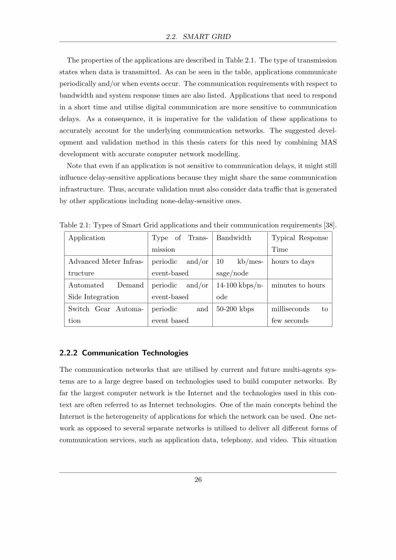
The properties of the applications are described in Table 2.1. The type of transmission
states when data is transmitted. As can be seen in the table, applications communicate
periodically and/or when events occur. The communication requirements with respect to
bandwidth and system response times are also listed. Applications that need to respond
in a short time and utilise digital communication are more sensitive to communication
delays. As a consequence, it is imperative for the validation of these applications to
accurately account for the underlying communication networks. The suggested devel-
opment and validation method in this thesis caters for this need by combining MAS
development with accurate computer network modelling.
Note that even if an application is not sensitive to communication delays, it might still
influence delay-sensitive applications because they might share the same communication
infrastructure. Thus, accurate validation must also consider data traffic that is generated
by other applications including none-delay-sensitive ones.
Table 2.1: Types of Smart Grid applications and their communication requirements [38].
Application Type of Trans-
mission
Bandwidth Typical Response
Time
Advanced Meter Infras-
tructure
periodic and/or
event-based
10 kb/mes-
sage/node
hours to days
Automated Demand
Side Integration
periodic and/or
event-based
14-100 kbps/n-
ode
minutes to hours
Switch Gear Automa-
tion
periodic and
event based
50-200 kbps milliseconds to
few seconds
2.2.2 Communication Technologies
The communication networks that are utilised by current and future multi-agents sys-
tems are to a large degree based on technologies used to build computer networks. By
far the largest computer network is the Internet and the technologies used in this con-
text are often referred to as Internet technologies. One of the main concepts behind the
Internet is the heterogeneity of applications for which the network can be used. One net-
work as opposed to several separate networks is utilised to deliver all different forms of
communication services, such as application data, telephony, and video. This situation
26

2.2. SMART GRID
is often referred to as network convergence [50].
Such a converged network, which is based on well established technologies and can
be built with off-the-shelf components, has numerous advantages over separate purpose-
built networks:
• More cost-efficient and easier network management because there is only one net-
work to maintain.
• Less expensive components due to a well adopted hardware and software market.
• Higher number of available experts in established technologies.
• Simple reconfiguration without the need of rewiring, which also makes the imple-
mentation of new ideas easier.
• One big converged network with a higher order of communication links is more
robust and resilient than smaller separate networks.
In the context of power system applications, various research has suggested the utilisa-
tion of communication networks that are based on a mix of existing Internet technologies.
Table 2.2 consolidates the most commonly suggested communication technologies and
their basic characteristics. Note that the maximum data rates and coverage are meant
to only give an indication of what is currently possible with typical off-the-shelf products
under ideal circumstances.
Table 2.2: Communication technologies for MAS and their basic characteristics [38, 51].
The maximum coverage represents the maximum possible distance between
sending and receiving equipment without communication relaying.
Technology Max. Data Rates Medium Type Max. Coverage
GSM (Global System
for Mobile Communica-
tions)
14.4 Kb/s wireless 10 km
GPRS (General Packet
Radio Service)
170 kb/s wireless 10 km
UMTS (Universal
Mobile Telecommunica-
tions System)
384 kb/s wireless 10 km
27

2.2. SMART GRID
LTE (Long-Term Evo-
lution)
100 Mb/s wireless 10 km
PLC (Powerline Com-
munication)
3 Mb/s power lines 3 km
WiMAX based on IEEE
802.16 standards
50 Mb/s wireless 50 km
ZigBee based on IEEE
802.15 standards
250 Mb/s wireless 50 m
WiFi based on IEEE
802.11a/b/g/n stan-
dards
600 Mb/s wireless 200 m
DSL (Digital Subscriber
Line)
100 Mb/s wires of telephone
networks
500 m
Bluetooth 3 Mb/s wireless 60 m
Ethernet over twisted
pair (IEEE 802.3-2008,
1000BASE-CX)
1 Gb/s twisted pair 100 m
Ethernet over optical fi-
bre (IEEE 802.3ba/bg)
100 Gb/s light 40 km
Gungor et al. [51] published a current overview of existing communication technologies
and standards for the future Smart Grid. It lists the advantages, limitations, and appli-
cations of technologies for wired and wireless communication. Suggested technologies for
wired communication included Digital Subscriber Lines (DSL), which utilise the wires
of telephone networks, and Power-line Communication (PLC), which uses the existing
powerlines to transmit data. Technologies for wireless communication can use existing
cellular networks for mobile phones (e.g. Global System for Mobile Communications
(GSM) and Universal Mobile Telecommunications System (UMTS) standards) and local
wireless networks such as WiFi, WiMAX, and ZigBee. In general, wired technologies
are more costly for new wide deployments but offer better bandwidth, reliability, and
security. In contrast, wireless technologies could reduce the installation costs but pro-
vide constrained bandwidth and security. Considering the wide array of possible power
applications and necessary network coverage, which ranges from easily accessible urban
28
2.2. SMART GRID
places to disperse rural places that are difficult to reach, the communication network
will most likely be based on a mix of technologies, similar to the Internet.
Patel et al. [38] categorised Smart Grid applications according to their their charac-
teristics and communication requirements such as latency and bandwidth. Applications
included advanced meter infrastructure, automated demand response, feeder automa-
tion, and electric vehicle charging. Commonly deployed communication technologies
were discussed for the given applications and the authors highlighted that there is no
silver bullet communication technology that fits all the needs of the Smart Grid appli-
cations. Similar to the previous research, it can be concluded that the use of a mix of
different existing technologies shown in Table 2.2 is highly likely.
Findings by the High-Level Advisory Group on ICT (information communication tech-
nology) [52] also came to the conclusion that there will be a mixture of technologies and
approaches. Key technologies were reported to include Internet based technologies such
as IP (Internet Protocol) based services. The services would be provided through wired
and wireless communication infrastructures such as GSM, GPRS, UMTS, Wifi, Blue-
tooth, DSL, and optical fibre.
Yuen et al. [53] explored the role and importance of communication for Smart Grid
applications. Because the choice of communication technologies in this context is over-
whelming, the authors give a decision guide that is based on different criteria such as
bandwidth needs, reliability (mean time to failure), security, available resources (wire
and wireless), and feasibility (e.g. wired coverage in rural areas). The authors sum-
marise that the communication network is the key enabler for Smart Grid applications
and that the ”right” communication system will be mix of available technologies.
Both, Hauser et al. [54] and Mak and Holland [55] looked at the inadequacies of the
existing communication infrastructure in the context of power systems. They raised the
concern that the current infrastructure, which is comprised of mostly slow (around a few
Kb/s), dedicated, and proprietary point-to-point communication channels, is inflexible,
too slow, and expensive to maintain. Replacing the current infrastructure by a faster
and more interconnected communication network that is based on widely adopted tech-
nologies and standards (e.g. TCP/IP based networks), would be cheaper (well adopted
hardware and software market), allow for new approaches (more performant connectiv-
ity), and make future development easier (no rewiring necessary) in the area of power
network management and control.
Yang and Barria [56], Yang et al. [57, 58] suggested communication infrastructures
29

2.3. SYSTEM MODELLING
for possible future distribution power network management to overcome the challenges
Distribution Network Operators (DNOs) have to face with regards to network opera-
tion and management due to the increasing number of distributed generators connected
to the existing UK distribution network. The proposed infrastructures used IP-based
communication (TCP and UDP) and communication technologies such as DSL and
PLC. Communication traffic modelling in form of implemented Quality of Service (QoS)
strategies was also proposed. A QoS enabled network has the ability to give differ-
ent priorities to different types of data traffic, which can improve the performance of
time-sensitive communication. Because the envisioned network management algorithms
assumed timely and reliable data communication, the authors highlighted that study-
ing the impact of communication performance (e.g. communication delays and dropped
data packages) on the overall operation would be imperative.
In summary, there has been a significant amount of research suggesting that the
communication infrastructure for MAS and future power systems will be based on a
converged network (i.e. one network for all communication needs) and a mix of existing
computer network communication technologies, which is in contrast to a possible idea
of newly developed purpose-built technologies and networks. Although the motivation
and cited literature focuses on power system applications, the advantages of converged
networks are applicable to various other industries such as telecommunication, manu-
facturing, financial services, and healthcare.
While converged communication networks have increasingly been adopted due to their
advantages, the design and validation of such networks and the many different prospec-
tive MAS applications deployed on it, pose significant challenges. A vast number of
different network equipment, network protocols, and applications compete for limited
resources, which mainly include processing power of the computer hardware (e.g. net-
work equipment) and physical communication channels (wired or wireless). This creates
large complex systems that are difficult to analyse. System modelling can help with this
issue.
2.3 System Modelling
System modelling is the act of building a representation of a system. While measurement
and experimentation can be applied to examine existing systems in the real world, system
modelling is an important approach for the design and development of non-existent
30

2.3. SYSTEM MODELLING
systems. Modelling can be a cost-efficient way to study the behaviour of such systems
and their performance before deployment. Advantages compared to real implementations
are:
• It is cheaper as not a lot of equipment is needed. In many cases one computer is
sufficient.
• It is not restricted by todays technologies and future characteristics can be mod-
elled.
• Models are usually quicker to build than to physically implement a testbed.
• Researchers have total control of the models and have access to all parameters.
This makes changes and analysis significantly easier.
Analysis and simulation are two traditional approaches used in modelling for commu-
nication networks [59]. The basis of the analytical approach is to describe the system
mathematically and create a mathematical model. This approach is usually preferred
over simulations because it is less computationally intense. However, it is only feasible
to describe small and simple systems mathematically. For large and complex systems,
the mathematical models are often simplified by making assumptions, which as a result
might not accurately represent the system in question. Although more computationally
intense, the simulation approach does not have this limitation and even complex sys-
tems such as communication networks and multi-agent systems can be modelled in every
possible detail. It is important to note that the question of the required level of detail
needs to be carefully considered for both modelling approaches.
2.3.1 Simulation
The simulation approach was utilised by this research to validate multi-agent systems
and communication networks. Shannon [60] defines simulation, which summarises well
its application in our context: ”the process of designing a model of a real system and
conducting experiments with this model of the purpose of understanding the behaviour
of the system and/or evaluating various strategies for the operation of the system.”.
According to Ingalls [61], a simulation consists of several structural components. It is
advantageous to define the main three components at this point:
31
2.3. SYSTEM MODELLING
Entities: They are the objects of a simulation program that interact with each other,
which cause changes to the state of the system. Each object has its own attributes
depending on what they represent. For computer network simulations, typical
examples of objects are data packages, communication links, or computer nodes.
Events and Activities: Events mark points in time where objects carry out activities.
Activities may create new events that are scheduled for a later time. A typical
example of an activity in the context of computer network simulations is a waiting
activity. When a data packet needs to be sent but the medium is not free, it has
to wait before it can be transmitted. Similarly, most network devices implement
buffers and queues where packets have to wait before it is their turn to be processed.
Scheduler: It maintains a simulation clock and a list of events. The simulation clock is
the basis for internal simulation time, which is also called logical time. In contrast,
physical time is the time in the real world and is often referred to as wall clock time.
Similar to physical time, logical time advances chronologically in the simulation
until it reaches a predefined end time. Events are associated with the time they will
happen in the simulation. As the scheduler advances simulation time, it executes
events chronologically and adds future events to the list if an activity requires it.
While simulations share the same structural components, there are different types of
simulations with respect to how the scheduler advances simulation time. The type of
simulation that depends on a logical time is called time-dependent simulation and can be
divided into time-driven and event-driven simulation. In time-driven simulations, logical
time advances by fixed time intervals. All events that are scheduled for a time during
an interval, are executed at the end of it. In contrast, in event-driven simulations, the
clock advances to the time of the next event on the event list.
Depending on the problem domain, this difference makes one type more suitable than
the other. In systems where events occur randomly in time and not at fixed time
intervals, the event-driven simulation is preferred. It only advances to times for which
events are actually scheduled and therefore saves processing time. This can be substantial
if the chosen time intervals are very small. Also, it avoids having to establish an optimal
fixed time interval to prevent more than one event occurring in one interval, which might
result in causal relationship issues as they are all executed at the end of the interval.
32
2.3. SYSTEM MODELLING
2.3.2 Computer Network Simulation
Computer networks are a typical problem domain where event-driven simulations, also
called discrete-event simulations, are used [62]. A computer network is a network of
computing devices that are connected via communication channels. The majority of
events are based on randomness. For example, communication protocols wait for a ran-
dom period of time before retransmitting data in case of a data collision on the medium.
Similarly, queuing strategies and generated data traffic rely heavily on probability dis-
tributions in order to account for the stochastic nature of computer networks.
Computer network simulators are utilised to build models of computer networks for
experimentation and analysis. They usually provide extensive modelling APIs, simula-
tion engines, data analysis capabilities, and model libraries, which includes a broad suite
of standard protocols and technologies to support rapid model development. Examples
of the most widely used simulators are the Network Simulator 2 (NS2) [63], Network
Simulator 3 (NS3)[64], QualNet[65], OMNeT++[66], SSFNet[67], NetSim[68] and the
OPNET Modeler [69].
Although most simulators readily provide or support the development of client/server
applications such as FTP (File Transport Protocol)[70], HTTP (Hypertext Transfer
Protocol)[71], database queries, and voice/video over IP, they lack the support for multi-
agent system development, which is peer-to-peer based. This is one of the reasons why
development and validation of MAS with the help of computer network simulator can
be extremely difficult or even impossible without significantly extending the simulators
themselves. Even if computer network simulators added distributed application support,
the developed application models could only be used for the purpose of simulation and
would have to be re-implemented to build a deployable multi-agent system. This would
make the development life-cycle longer and more complex but more importantly, the
re-implemented agent-based application code would have to be validated again. The
method proposed in this research overcomes this limitation by federating network simu-
lation with MAS development frameworks, which allows for the validation of deployable
multi-agent systems through simulation.
33

2.4. PREVIOUS APPROACHES TO MAS DEVELOPMENT AND VALIDATION
2.4 Previous Approaches to MAS Development and Validation
The majority of prior research on MAS development can be categories based on three
different development approaches. Research in the first category develops MAS without
accounting for the influence of the communication infrastructure. The second approach
is to separate the validation of the application and the communication infrastructure.
The last category of research develops applications as models in network simulators.
2.4.1 Development Without Communication Network Validation
This first category of research only validates the correct functionality of the developed
MAS without accounting for the influence of the communication system. While the re-
search in this category actually produces deployable systems (opposed to only simulation
models), this approach is not suitable for time-critical and delay-sensitive application
development because the influence of the communication system can be significant. Even
non-time-critical systems that are comprised of various different applications competing
to use the same communication infrastructure, might be ill-represented by not taking
communication performance into account. Most authors using this approach are aware
of this situation and acknowledge its limitations.
The following examples in the literature only focused on the agent application aspect
without taking communication delays into account.
Ren et al. [2] proposed a dynamic team forming mechanism to manage multi-agent
systems for power system restoration. The agents were implemented with the help of
the JACK Agent software, while the power simulations were done in MATLAB with the
help of the MATPOWER package. The exchange of information between the power sim-
ulation and the MAS relied on exporting and importing spread sheets. Although system
restoration is a time-critical application, the impact of the communication network was
not considered.
Pipattanasomporn et al. [72] discussed the development of a multi-agent system that
can disconnect and stabilize a microgrid from the local utility when upstream outages
are detected. The MAS was implemented with the help of ZEUS agent toolkit and
the agents used TCP to communicate. While the microgrid hardware was simulated
in MATLAB, there was no simulation of the envisioned communication infrastructure.
As a consequence, the presented results of the time-critical fault protection application,
which suggested that the system could operate in the order of a few milliseconds, do not
34
2.4. PREVIOUS APPROACHES TO MAS DEVELOPMENT AND VALIDATION
accurately represent a realistic scenario because they do not include any delays caused
by the communication infrastructure. These delays can be significant considering the
timescale of the operation in question.
Another example of a MAS for distribution system restoration was published by
Solanki et al. [4]. The research developed a MAS in JADE that restores a power system
after a fault. The Virtual Test Bed (VTB) [73], which provides a computational envi-
ronment for modelling and dynamic simulation of power systems, was used to account
for the power system behaviour. It interfaced with JADE to provide a combined power
system and MAS simulation. The presented results suggested that the application could
react in less than 1 second. Similarly to the previous research, the method did not
account for the impact of the communication network and therefore is not accurate.
Dimeas and Hatziargyriou [9] suggested a MAS for the distributed control and oper-
ation of microgrids with the focus on market participation. The MAS was implemented
in JADE and agents participated in an auction system for selling and buying electrical
energy. The presented auction algorithm takes numerous iterations to converge to a solu-
tion, which involves agent communication for every iteration. Despite the heavy reliance
on agent communication, no communication delays were considered, which the authors
acknowledged are an important element that needs further investigation. In contrast to
the previous examples, this type of application does not have to operate within seconds.
However, the extremely high number of agent messages sent for every negotiation cycle,
which means hundreds of messages depending on the number of participating agents,
can contribute a great deal to the time the system needs to operate. Thus not including
the communication aspect can lead to inaccurate performance predictions.
Another example of MAS development that did not consider the impact of communi-
cation delays was published by Nagata et al. [3]. The research proposed a multi-agent
approach to power system restoration that can decide what switching devices to open or
close in order to achieve a sub-optimal restoration configuration after a fault. The agent
system was written in JAVA, which according to the results could reach a solution within
2 seconds. Again, the results are in a range in which the omission of communication
delays lead to inaccurate results.
35

2.4. PREVIOUS APPROACHES TO MAS DEVELOPMENT AND VALIDATION
2.4.2 Independent MAS Development and Communication Analysis
The second approach separates MAS development and performance analysis through
simulation. Typically this is done in two steps. In the first step, the MAS is developed
and a communication traffic profile is obtained by running the system. This profile
contains information such as the time of data transmission and the amount and type of
traffic. In the second step, this profile is modelled with a computer network simulator to
investigate the communication delays the agent-based applications would have to deal
with. If the traffic profile is simple the communication delays are simulated first and
then incorporated into the MAS but only for the purpose of validation.
While this approach does include basic validation it is only accurate for small and
simple MAS. The behaviour and traffic profile of larger and more complex agent-based
applications are directly influenced by the communication delays and therefore it is
absolutely necessary to simulate the MAS and communication network at the same
time. Another issue with this approach is that considering a large number of distributed
agents, the modelling of the traffic profiles can be a laborious task if one wants to obtain
accurate results.
Several researchers have used this approach to add separate network simulations to
supplement the MAS development and provide more accurate validation.
Garlapati et al. [49] used the previously discussed approach to validate the developed
MAS in two separate steps. They proposed an agent-based protection scheme for zone 3
relays. The power simulations were done with the help of Positive Sequence Load Flow
(PSLF) software. In the first step, statistical values for relay failures were calculated
with PSLF. These values were used to create a traffic profile that would represent the
behaviour of the agent-based protection scheme. This profile included information about
agent communication such as communication time and size of the messages. This was
then implemented in the second step in the network simulator NS2 in order to obtain the
average communication delays of the system through simulations. As motivated earlier,
only MAS that produce easily identifiable and simple to implement traffic profiles can
be validated with this approach.
The next work is an example in which the communication delays were simulated in
the first step. Coury et al. [5] proposed an agent-based current differential relay pro-
tection scheme. The communication delays and dropped messages were first simulated
in NS2. They were then considered when developing and subsequently evaluating the
36
2.4. PREVIOUS APPROACHES TO MAS DEVELOPMENT AND VALIDATION
performance of the agent-based system. This approach was only feasible because the
communication behaviour of the agent-based application was simple and the traffic pro-
file easy to predict and describe without experimentation. For example, the application
sent a constant stream of data with a fixed payload at any time. While this approach was
valid for that work, it is not suitable for most MAS development in which the behaviour
of the agents is more complex and difficult to predict without simulations.
Tahboub et al. [13] investigated the functionality of a MAS and communication traffic
separately. They presented work on modelling and simulation of secure automatic energy
meter reading. The authors used mobile agents that toured from one meter to the next
to carry out the meter readings. The communication network and meters were simu-
lated with OPNET Modeler while the mobile agents were implemented in JADE, which
served as a separate simulation to verify the functionality of the MAS. This verification
did not account for the communication infrastructure but the separate network simula-
tions were used to get an indication of the impact of the agents on the infrastructure
such as link utilisation and queuing delays. Although the network simulation provided
additional information, the agent-based application was not accurately simulated. Only
a simulation that accounts for both aspects, applications and communication network,
could provide this.
2.4.3 Development and Analysis Through Communication Network
Modelling
Research that is based on the third approach designs and analyses MAS by modelling
agent applications within the computer network simulator. It does not implement a
deployable MAS. It allows for an accurate validation of the models but the agent models
have to be ported onto an actual MAS platform before deployment. The reason for this
is that simulators were not designed to support the development of deployable MAS,
which requires an agent-based middleware providing a platform for the agents to exist
in. Because the actual MAS code is not the same as the simulated agent models, the
deployed system might behave differently to the simulated one. Another shortcoming of
MAS development within network simulators is the lack of support for the agent-oriented
programming paradigm and peer-to-peer communication.
The majority of researchers have used either NS2 or OPNET Modeler to develop and
simulate their agent application models. For example, Lin et al. [74] and Lin et al. [75]
37
2.4. PREVIOUS APPROACHES TO MAS DEVELOPMENT AND VALIDATION
presented work on a co-simulation framework of PSLF and NS2 for power applications.
The agent-based applications were developed in NS2. On the other hand, He et al.
[76] utilised OPNET to model and simulate smart-meter applications and power line
communication (PLC) infrastructure.
Research that neither used NS2 nor OPNET Modeler was presented by Song et al. [77].
The authors built a discrete-event network simulator in Erlang based on the Sim-Diasca
simulation engine. The smart-meter agent applications were modeled in the simulator
and most other models, such as link and computer node models, were implemented from
scratch. Although the simulator was build for the purpose of the presented application,
which according to the authors allows for large-scale simulations, the porting or build-
ing a deployable MAS that behaves exactly as the simulated system is still the major
challenge.
Taylor et al. [78] developed a framework that enables the execution of Java applications
in the network simulator NS2. It utilises the Java Native Interface (JNI [79]) to run
Java code in a Java Virtual Machine (JVM) as part of a C++ application object in NS2.
This approach is different to all the previous examples because it acknowledges the
limitations of application development within network simulators and provides a means
to run deployable Java code. While this framework seems viable for general Java-based
applications, it also lacks the standardised agent-based middleware, which is crucial for
MAS development and subsequent deployment. The method presented in this thesis is
similar to this work in that it also has the aim to enable the development and validation
of deployable application code. However, it is different in that the proposed method also
accounts for the needed agent-based middleware.
In summary, the three approaches do not support the development of deployable MAS
using agent-oriented programming and accurate validation that also accounts for the
communication network. Therefore the work in this thesis suggests a new method for
development and validation, which federates a MAS development toolkit with a network
simulator. This would allow for the development of a deployable system through the
MAS toolkit while at the same time accounting for the communication network (through
modelling) at the validation stage.
38

2.5. FEDERATIONS
2.5 Federations
The method in this work proposes to combine the functionality of a MAS platform with
the functionality of a network simulator to support MAS development and validation. It
is based on co-simulating (also know as federating) existing tools as opposed to building
new tools from scratch because it is extremely time and resource intensive to provide
functionality that is at least on a par with best-in-class tools. For example, a new
tool would have to provide a MAS development framework, a standardised agent-based
middleware, a network modelling framework, a simulation engine, and model libraries
of numerous standard communication protocols and technologies. In addition, a new
simulation engine with new model libraries would have to be validated before the research
community would consider adopting it. Utilising the functionality of already adopted
tools does not face these issues.
However, a federation of existing tools comes with its own challenges. The main
hurdles are time management, interfacing issues, and data exchange. They are discussed
in a recent overview paper by Wang et al. [80].
Time management deals with the synchronisation of the federates and ensures that
they start at the same time and advance time in a synchronised manner in order to
process events in the correct order. This is a significant challenge especially if the
federates do not share the same internal scheduling mechanism, which is the case for
time-dependent and continuous systems.
Standalone tools lack the capability to interface with external tools. In order to realise
any kind of interaction between the federates, they must provide interfaces. For example,
the proposed method in this work uses the High-Level Architecture (HLA) [81] standard
as the distributed simulation modelling architecture. This standard defines a runtime-
infrastructure (RTI), which for example provides overall time management. The RTI
needs to interface with all federates to establish a two-way communication. Adding this
capability to existing tools is not trivial and requires strategies of re-implementation,
extension of intermediate code, and usage of external APIs as discussed by Straburger
[82].
The third challenge is the question of how to exchange data objects between the
federates. This includes the transport of the data as well as interpretation of it. For
example, in a federation of a MAS and network simulator, specific properties of the agent
messages, such as payload size, sender, and recipients need to be shared in a format that
39

2.5. FEDERATIONS
is understood by both federates.
There are a few successful examples in the literature that have used this approach
to federate different tools. However, none of them has federated MAS and computer
network simulators with the purpose of validating the agent-based application code and
the overall system function. Table 2.3 lists previous research examples including the
federated tools, time synchronisation method, and used distributed simulation modelling
architecture to provide necessary interfaces between the federates. While the examples
focus on power, network, and agent-based tools, some research also suggested the use of
co-simulations in other fields such as manufacturing [83] and supply chain management
[84].
Table 2.3: Examples and Comparison of Co-Simulations.
Research Federates Synchronisation Modelling Archi-
tecture
Lin et al. [74] PSLF, NS2 event-driven own interface im-
plementation
Li et al. [85] VTB, OPNET Modeler time-stepped own interface im-
plementation
Liberatore and
Al-Hammouri
[86]
Modelica, NS2 time-stepped own interface im-
plementation
Daniele Gianni
and Pieroni [87]
JADE, JADE event-driven HLA
Hopkinson et al.
[88]
PSLF/EMTDC, NS2 time-stepped HLA
Morejon et al. [89] VTB, JADE time-stepped CORBA
As part of the proposed method, this research suggests a federation of JADE and
OPNET Modeler, which has been realised in the form of a platform called MAC-Sim
(Multi-Agent and Communication Simulator). The synchronisation is based on discrete
events and the used distributed simulation modelling architecture is based on the HLA
standard.
40

2.6. SUMMARY
2.6 Summary
This chapter described background information and reviewed relevant previous work.
It showed that multi-agent systems are utilised as a means to solve complex problems
and that they are widely suggested as a method to realise highly distributed, flexible,
and fault tolerant applications for the future Smart Grids. For example, agent-based
applications were used in the areas of automated meter infrastructure, automated de-
mand response, and feeder automation. Previous research was presented that suggested
that these applications are likely to utilise a converged network based on a mix of differ-
ent Internet technologies. Because some Smart Grid applications were identified to be
time-critical and sensitive to communication delays, it is crucial to not only validate the
correct function of the multi-agent system but also account for delays caused by agent
communication. This is seen as challenging due to the large number of heterogeneous
applications, network equipment, and network protocols that make up the whole system
and compete for limited resources. Modelling and simulation of computer networks is a
method that can help analyse the impact of communication networks. Previous research
was reviewed that used approaches that included network simulations to supplement
their MAS development and provide more accurate validation results. However, none of
them allowed for a completely accurate validation of a deployable MAS. Thus, this work
suggests a new method that is based on the concept to federate a MAS framework and
communication simulator. The main difference to previous approaches is that (a) it is
able to validate the MAS that will actually be deployed and (b) validates the whole sys-
tem (applications and communication networks) by means of one integrated simulation.
The design of the suggested federation, or co-simulation, is discussed in the subsequent
chapters.
41
3 Co-Simulation Platform Design and
Architecture
3.1 Introduction
Building a co-simulation of independent software tools is a considerable challenge. One
issue is the exchange of data between the federated tools because they normally run
on their own and do not expose internal data to external entities. Another significant
obstacle is the synchronisation of the overall simulation execution to ensure that the
independent tools start at the same time and progress at the same pace. This particularly
holds true for the federation of multi-agent systems and discrete-event communication
simulations. Multi-agent systems consist of distributed agents that are run in parallel in
real-time whereas discrete-event simulators are based on the concept of simulation time
and time advances from one event to the next. This difference makes synchronisation
extremely difficult.
The proposed architecture presented in this chapter addresses these challenges and al-
lows for a co-simulation of multi-agent systems and a communication network simulator.
It also describes what changes need to be made to the federated tools. The architecture
itself is generic but a simulation platform has been developed that is based on it and
presented in Chapter 4.
3.2 Architecture Overview
The architecture to build a discrete-event co-simulation of multi-agent systems and com-
munication networks is illustrated in Figure 3.1. It consists of three main components,
which are a multi-agent system (MAS) development platform, a network simulator, and
a runtime infrastructure (RTI). The MAS platform and the network simulator are called
the federates. The MAS is made up of agent models (An), which are developed with the
42

3.2. ARCHITECTURE OVERVIEW
Figure 3.1: Overview of the architecture and relationships of the simulation platform
components. Every agent An is associated with a network node Nn (n =
1, . . . , 5).
MAS development framework and subsequently run on its platform. On the other hand,
the communication network models are developed within the communication network
simulator. They are comprised mainly of node models (Nn) and communication link
models connecting them. Every agent is associated with a node, which represents the
hardware device on which it would be deployed in reality. The RTI is a software pro-
gram that provides services for simulation management, object management, and time
management. For this architecture, it is based on standardised interfaces, which make
it possible to extend the co-simulation platform by other simulation tools (depicted as
dotted squares in Figure 3.1).
The following simplified example should help understand the basic roles and interac-
tions of the platform components before explaining them in detail later in this chapter.
Consider the MAS model and communication network model illustrated in Figure
3.2. In this example the MAS to be simulated consists of 5 agents (An, n=1,...,5),
which are supposed to run on hardware that is represented by the node models (Nn,
n=1,...,5) of the communication network model. The example shows how an agent
message exchange between agent A1 and agent A4 is accurately simulated. Prior to the
co-simulation execution, the RTI ensures that both federates start at the same time.
After that, and for the remaining time of the co-simulation, it is responsible for granting
43

3.2. ARCHITECTURE OVERVIEW
time advancements to the federates so that they can execute their next events in the
correct order. When the RTI grants time to the MAS platform to run agent A1, it
sends a message to A4 (indicated by the dashed arrow between A1 and A4). Instead
of delivering the message directly, the MAS platform sends an interaction (indicated by
the solid arrows) to the communication network simulator to tell it to simulate this data
transfer. All interactions are always sent via the RTI. The whole co-simulation advances
in time until the simulation of the data transfer from node N1 to node N4 (indicated
by the dotted arrows) is completed. This process is usually interspersed with other
scheduled events of the MAS platform or the network simulator but for this example
there are no other events. Upon completed data transfer, the network simulator informs
the MAS platform that agent A4 has received the data. As a result, the RTI grants
time to the MAS platform to allow for the execution of agent A4 so that it can react
to the received message from agent A1. The integration of the communication network
simulator into the agent communication process ensures that communication delays are
accurately accounted for.
Figure 3.2: Illustration of message passing within the simulation platform. A message
sent from agent A1 to agent A4 is relayed via the RTI to the associated
network nodes of the network simulation.
After this overview, the next sections describe the components and their interactions
in more detail.
44
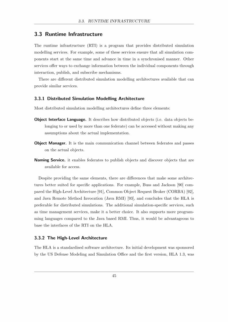
3.3. RUNTIME INFRASTRUCTURE
3.3 Runtime Infrastructure
The runtime infrastructure (RTI) is a program that provides distributed simulation
modelling services. For example, some of these services ensure that all simulation com-
ponents start at the same time and advance in time in a synchronised manner. Other
services offer ways to exchange information between the individual components through
interaction, publish, and subscribe mechanisms.
There are different distributed simulation modelling architectures available that can
provide similar services.
3.3.1 Distributed Simulation Modelling Architecture
Most distributed simulation modelling architectures define three elements:
Object Interface Language. It describes how distributed objects (i.e. data objects be-
longing to or used by more than one federate) can be accessed without making any
assumptions about the actual implementation.
Object Manager. It is the main communication channel between federates and passes
on the actual objects.
Naming Service. it enables federates to publish objects and discover objects that are
available for access.
Despite providing the same elements, there are differences that make some architec-
tures better suited for specific applications. For example, Buss and Jackson [90] com-
pared the High-Level Architecture [91], Common Object Request Broker (CORBA) [92],
and Java Remote Method Invocation (Java RMI) [93], and concludes that the HLA is
preferable for distributed simulations. The additional simulation-specific services, such
as time management services, make it a better choice. It also supports more program-
ming languages compared to the Java based RMI. Thus, it would be advantageous to
base the interfaces of the RTI on the HLA.
3.3.2 The High-Level Architecture
The HLA is a standardised software architecture. Its initial development was sponsored
by the US Defense Modeling and Simulation Office and the first version, HLA 1.3, was
45
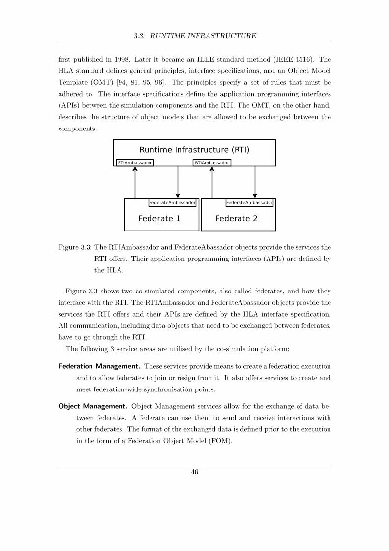
3.3. RUNTIME INFRASTRUCTURE
first published in 1998. Later it became an IEEE standard method (IEEE 1516). The
HLA standard defines general principles, interface specifications, and an Object Model
Template (OMT) [94, 81, 95, 96]. The principles specify a set of rules that must be
adhered to. The interface specifications define the application programming interfaces
(APIs) between the simulation components and the RTI. The OMT, on the other hand,
describes the structure of object models that are allowed to be exchanged between the
components.
Figure 3.3: The RTIAmbassador and FederateAbassador objects provide the services the
RTI offers. Their application programming interfaces (APIs) are defined by
the HLA.
Figure 3.3 shows two co-simulated components, also called federates, and how they
interface with the RTI. The RTIAmbassador and FederateAbassador objects provide the
services the RTI offers and their APIs are defined by the HLA interface specification.
All communication, including data objects that need to be exchanged between federates,
have to go through the RTI.
The following 3 service areas are utilised by the co-simulation platform:
Federation Management. These services provide means to create a federation execution
and to allow federates to join or resign from it. It also offers services to create and
meet federation-wide synchronisation points.
Object Management. Object Management services allow for the exchange of data be-
tween federates. A federate can use them to send and receive interactions with
other federates. The format of the exchanged data is defined prior to the execution
in the form of a Federation Object Model (FOM).
46
3.4. EXTENSIONS TO MULTI-AGENT SYSTEMS
Time Management. The control of time advancements of the federated components
is a key issue. The time management services allow each federate to advance
its simulation time in synchronisation with the other federates. It also manages
the timely delivery of interaction events by adding time-stamps and prohibiting
the delivery of past interactions. A detailed explanation of the time management
concepts can be found in [97].
There are other service groups defined by the HLA that are not needed by this archi-
tecture. An overview of all services can be found in [91].
Overall, the HLA standard defines all the simulation services needed for the discrete-
event co-simulation platform. However, the individual tools (the federates), which are
stand-alone tools, have to be extended to use the provided services and to integrate
with the platform. The main issues are that the individual tools were not designed to
(a) communicate with an RTI, (b) exchange information with other tools, and (c) let
external time management services control their execution. The next sections discuss
these issues in detail and present a solution.
3.4 Extensions to Multi-Agent Systems
In general a MAS framework needs to be extended in 3 main areas in order to be
federated with a communication network simulator:
Agent execution: Agents need to be executed in a controlled way, which is necessary
to allow for a synchronised execution of a MAS and a network simulator.
Message exchange: Data needs to be exchanged between the simulation components.
In particular data about agent messages, which include vital information for the
simulator such as message sizes, source and destination of the message.
RTI communication: The MAS needs to be able to interface with the RTI in order to
use the simulation services that it offers.
3.4.1 Agent Execution
Using a MAS toolkit that can run its agents in real-time and federate it with a discrete-
event simulator is challenging. The agents created with the toolkit are run in real-time
47
3.4. EXTENSIONS TO MULTI-AGENT SYSTEMS
on the provided runtime environment. They are usually executed on computer hardware
as independent processes or threads. While this is fine for deployed systems, it causes
two main issues when used for simulations.
Figure 3.4: Error introduced by running several agents on the same hardware.
The first issue pertains to the execution of a number of agents on one computer
hardware that would in reality run on different devices. The execution times of the agents
running on one computer hardware cannot accurately represent a system where the
same agents run on different devices. Figure 3.4 illustrates this problem using a simple
example. Consider the situation where agents A1 and A2 run on separate hardware in
real life but are simulated on one computer. In this example, both agents only run one
task (task T1 and task T2) that start exactly at the same time and take the same time
to finish. The task T2 sends an agent message to agent A1 at the end of it, which is
denoted by the arrow from A2 to A1. If these two agents are run on one computer for the
purpose of simulations, the agent’s tasks cannot be processes in parallel unless there are
as many CPUs as agents available, which is not feasible even for small MAS that only
consist of a few agents. If only one CPU is available, the agent’s tasks are broken down
into computer instructions that are executed one after another. In computer science
48

3.4. EXTENSIONS TO MULTI-AGENT SYSTEMS
this way of execution is often referred to as quasi-parallel execution. Usually the order
of the instructions of both tasks are interlaced but for this example it is assumed that
the whole task T1 is executed before task T2. It can be easily seen that even with
the assumption that the message transfer is simulated correctly (i.e. it takes the same
amount of time to send the message from agent A2 to A1), there will be a time error
that is caused by the inability to process tasks in parallel and the fact that it takes a
different amount of time to process the same tasks on different hardware. In MAS these
kind of errors accumulate over time as tasks are predominately started by received agent
messages rather than fixed predefined times. Therefore, running a MAS on one hardware
to simulate a real system, which is made up of numerous devices, is not representative
and suitable in most cases. It also makes debugging significantly more difficult as the
same simulation may produce different simulation results.
The second issue is the synchronisation of real-time and discrete-event systems. Figure
3.5 shows the difference in their execution with respect to real-time and exemplifies the
fundamental problem that this causes. The MAS at the top is made up of 3 agents
(A1, A2, A3), which run in real-time. Agents A1 and A2 execute their tasks (task T1,
task T2), which send an agent message (M1 and M2) when they finish. The transfer of
both agent messages, which is denoted by the dotted arrows, would take the time t1 for
the deployed system. The bottom half of the figure shows how a discrete-event network
simulator would simulate the agent message transfer. For this example it is assumed
that each transfer is correctly simulated by two internal network events. The first event
E1-1, which simulates the first part of the message M1 transfer, is at the top of the
event list, followed by event E2-1 for the message M2 transfer. As both messages M1
and M2 happen at the same time, the network simulator executes both events before
advancing its simulation time to t0. Events E1-2 and E2-2 are next on the event list and
mark the end of the message simulation for M1 and M2. They are usually scheduled
by the previous events. After finishing the execution of the last two events E1-2 and
E2-2 the simulation time advances to t1, which represents how long the message transfer
would have taken in the real world. However, because the simulation takes longer to
derive the results than time t1, the results (i.e. time of the message transfers) are
reported back to the MAS too late, which introduces errors. For very small MAS and
for small communication networks models, the network simulation might be fast enough
to provide results in real-time. Network emulation (see [98] for an example) makes use
of this property but this is not a viable option for the presented architecture due to the
49
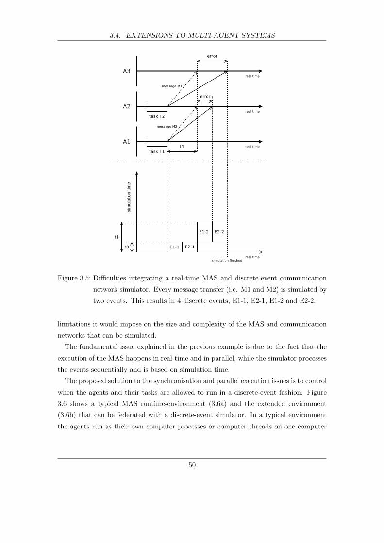
3.4. EXTENSIONS TO MULTI-AGENT SYSTEMS
Figure 3.5: Difficulties integrating a real-time MAS and discrete-event communication
network simulator. Every message transfer (i.e. M1 and M2) is simulated by
two events. This results in 4 discrete events, E1-1, E2-1, E1-2 and E2-2.
limitations it would impose on the size and complexity of the MAS and communication
networks that can be simulated.
The fundamental issue explained in the previous example is due to the fact that the
execution of the MAS happens in real-time and in parallel, while the simulator processes
the events sequentially and is based on simulation time.
The proposed solution to the synchronisation and parallel execution issues is to control
when the agents and their tasks are allowed to run in a discrete-event fashion. Figure
3.6 shows a typical MAS runtime-environment (3.6a) and the extended environment
(3.6b) that can be federated with a discrete-event simulator. In a typical environment
the agents run as their own computer processes or computer threads on one computer
50
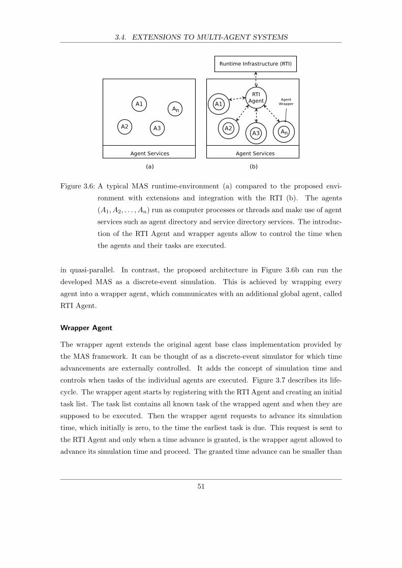
3.4. EXTENSIONS TO MULTI-AGENT SYSTEMS
Figure 3.6: A typical MAS runtime-environment (a) compared to the proposed envi-
ronment with extensions and integration with the RTI (b). The agents
(A1, A2, . . . , An) run as computer processes or threads and make use of agent
services such as agent directory and service directory services. The introduc-
tion of the RTI Agent and wrapper agents allow to control the time when
the agents and their tasks are executed.
in quasi-parallel. In contrast, the proposed architecture in Figure 3.6b can run the
developed MAS as a discrete-event simulation. This is achieved by wrapping every
agent into a wrapper agent, which communicates with an additional global agent, called
RTI Agent.
Wrapper Agent
The wrapper agent extends the original agent base class implementation provided by
the MAS framework. It can be thought of as a discrete-event simulator for which time
advancements are externally controlled. It adds the concept of simulation time and
controls when tasks of the individual agents are executed. Figure 3.7 describes its life-
cycle. The wrapper agent starts by registering with the RTI Agent and creating an initial
task list. The task list contains all known task of the wrapped agent and when they are
supposed to be executed. Then the wrapper agent requests to advance its simulation
time, which initially is zero, to the time the earliest task is due. This request is sent to
the RTI Agent and only when a time advance is granted, is the wrapper agent allowed to
advance its simulation time and proceed. The granted time advance can be smaller than
51

3.4. EXTENSIONS TO MULTI-AGENT SYSTEMS
Figure 3.7: The flowchart of the life-cycle of the wrapper agent.
the time requested. After advancing its simulation time, the wrapper agent executes all
tasks for the current simulation time. The tasks can create new tasks which need to be
scheduled by updating the task list in the next step. Finally, the wrapper agent asks
the RTI Agent for the next time advance. This continues until the simulation end time
is reached.
The wrapper agent implementation must also provide a means to define the execution
times of the agents’ tasks. This is desired because the time to execute a task on the
simulation hardware differs from the execution time on the deployed hardware. The
differences can be significant considering that simulations are run on powerful computers
whereas the numerous agents might be deployed on comparable slow and cheap hardware.
One simple way to add this time information is to define an additional method that
returns the execution time of the task in question.
RTI Agent
The RTI Agent provides time management for all wrapper agents. Its life-cycle can also
be compared to a discrete-event simulator (see Figure 3.8). At the start the RTI Agent
registers with the RTI of the simulation platform and receives all initial registration and
time advance requests from the wrapper agents. With these requests the RTI Agent
builds an initial list of time advance grant events. Every time advance grant event is
associated with a wrapper agent and the time advance it requested (see Figure 3.9).
52

3.4. EXTENSIONS TO MULTI-AGENT SYSTEMS
Figure 3.8: The flowchart of the life-cycle of the RTI Agent.
The execution of such an event results in a time advance grant sent to the associated
wrapper agent so that it can run the agent’s tasks. After building the initial event list,
the RTI Agent has all the information to request a time advance to the earliest event on
the list. The request is sent to the RTI, which provides time management to the whole
co-simulation. Upon receipt of a time advance grant, which can be smaller than the
time requested, the RTI Agent advances its simulation time. Next, it executes the time
advance grant events for the current simulation time, which result in wrapper agents
running their agent’s tasks and requesting new time advances. Finally, the RTI Agent
updates the event list with the newly received requests and then requests a time advance
itself. Similarly to the wrapper agents, this loop continues until the simulation end time
is reached.
On the whole, the wrapper agents and the RTI Agent implement the functionality
of a discrete-event simulator within the MAS runtime-environment. This solves the
previously described issues regarding parallel agent execution and the synchronisation
with a discrete-event network simulator. The controlled execution of agents as opposed
to parallel execution also makes debugging MAS easier as the same MAS simulation will
always produce the same results. Another advantage of this design is that the added
functionality is completely transparent to the original agents provided that the wrapper
agent implementation exposes the same application programming interfaces (APIs) as
the chosen MAS framework. This means that agent models that are used for simulations
can be deployed directly without major changes. An example of the changes needed can
53

3.4. EXTENSIONS TO MULTI-AGENT SYSTEMS
Figure 3.9: A chronologically sorted event list initially only contains time advance grant
events (t), which are associated with an execution time and a wrapper agent.
The execution of an event t grants time to the associated wrapper agent.
be found later in chapter 5.9, which presents a case study.
3.4.2 Agent Message Exchange
Another mechanism of the MAS framework that needs to be changed in order to be
integrated with the co-simulation platform is the way agent messages are exchanged.
Most MAS frameworks offer functions to create, send, and receive agent messages. The
messages are transported directly from the sender to the receiver by message transport
services of the frameworks. However, for the purpose of the co-simulation, there needs
to be a way to intercept messages, store them, and deliver them later at the correct
simulation time based on the results of the communication network simulator.
The previously introduced wrapper agents and RTI agent also provide this function.
The wrapper agent implementation overrides the functions that pertain to message trans-
fer and can therefore intercept agent messages. The intercepted messages are then sent
to the RTI agent using the native message transport services of the MAS framework.
The RTI agent saves the whole message in memory, including transport information such
as the sender’s name and the receivers’ names, and generates a unique message identifier
(ID) for the message. This message ID together with a current timestamp (based on
simulation time), the transport information, and the overall message size is then sent
to the network simulator through the RTI. The network simulator will then use this
information to start simulating the message transfer.
Note that the original agents can only send or receive messages when their tasks
54

3.4. EXTENSIONS TO MULTI-AGENT SYSTEMS
are executed by their wrapper agent at discrete simulation times. The described steps
of the message interception all happen without advancing simulation time. Thus, the
message timestamp reflects exactly the simulation time when the messages were sent by
the original agents.
Once the network simulator has finished the simulation of a message transfer, the RTI
Agent will receive a notification that similarly includes a message ID, transport informa-
tion, and a timestamp for the time the transfer was concluded. With this information
the RTI agent adds a message event (see Figure 3.10) to its event list, which is scheduled
according to the timestamp. During the execution of the message event, the RTI agent
looks up the previously saved agent message and delivers it directly to the receiving
agent. It then grants time to the agent so that it can react to the message if necessary.
Figure 3.10: The chronologically sorted event list that also contains message events. Mes-
sage events are used to deliver agent messages at the correct simulation
time.
When exchanging agent message information between a MAS framework and a net-
work simulator, there needs to be a way to associate the agents with the network nodes
in the network simulator. For example, if an agent A1 sends a message to an agent A2,
the network simulator has to know from which network node the message originates and
is sent to. Agents and network nodes are identified by identifiers (ID) that are unique
to their environment. There are two options to make this association between the two
separate environments. The first is to assign the same IDs to both, the agents and their
associated network nodes. The second option, which is also the more flexible one, is to
55

3.4. EXTENSIONS TO MULTI-AGENT SYSTEMS
create a lookup table of corresponding agent and node IDs. This external table, which
could be implemented as a data file, is created before the simulation starts and must be
accessible to both federates.
The explained mechanisms of intercepting agent messages, saving messages, and send-
ing notifications between the federates make the accurate simulation of message ex-
changes possible.
3.4.3 Communication Between Agent System and RTI
In order to use the simulation services provided by a HLA-based RTI, a MAS must
implement a HLA compatible mechanism to communicate with it. In this proposed
architecture, the previously introduced RTI Agent provides this mechanism (see Figure
3.6b). The RTI is the only external entity the RTI Agent, and the MAS for that matter,
communicates with. This means that all data exchange with other federates has to go
through the RTI.
As shown in Figure 3.1 and in accordance with the HLA specification, the RTI Agent
uses the RTIAmbassador object for outgoing communication and implements a Fed-
erateAbassador object to receive callbacks for incoming communication from the RTI.
Both, objects and their member functions, are defined in the HLA specification [81].
The RTI Agent communicates with the RTI at 3 states in its life-cycle, that are at the
initialisation, request time advance, and simulation end states (see Figure 3.8).
During initialisation, which only happens at the beginning of the life-cycle, the RTI
Agent takes care of the initial setup. First, it joins the co-simulation (federation) and
sets time management parameters. The HLA standard requires every federate to inform
the RTI during initialisation what degree of involvement it has in terms of time man-
agement. There are two parameters to consider: time-regulating and time-constrained.
A time-regulating federate regulates time advancements of all other federates that are
time-constrained. A time-constrained federate is one whose time advancements are re-
strained by time-regulating federates. Thus, if all federates are time-constrained and
time-regulating, they are fully time synchronised and no federate can run ahead of the
rest of the federation. The RTI Agent joins as time-regulating and time-constrained.
The network simulator will also join with the same parameters, which makes sure that
both federates are in complete synchronisation at all times. Then, the RTI Agent pub-
lishes and subscribes to data objects (i.e. agent message information) that need to be
56
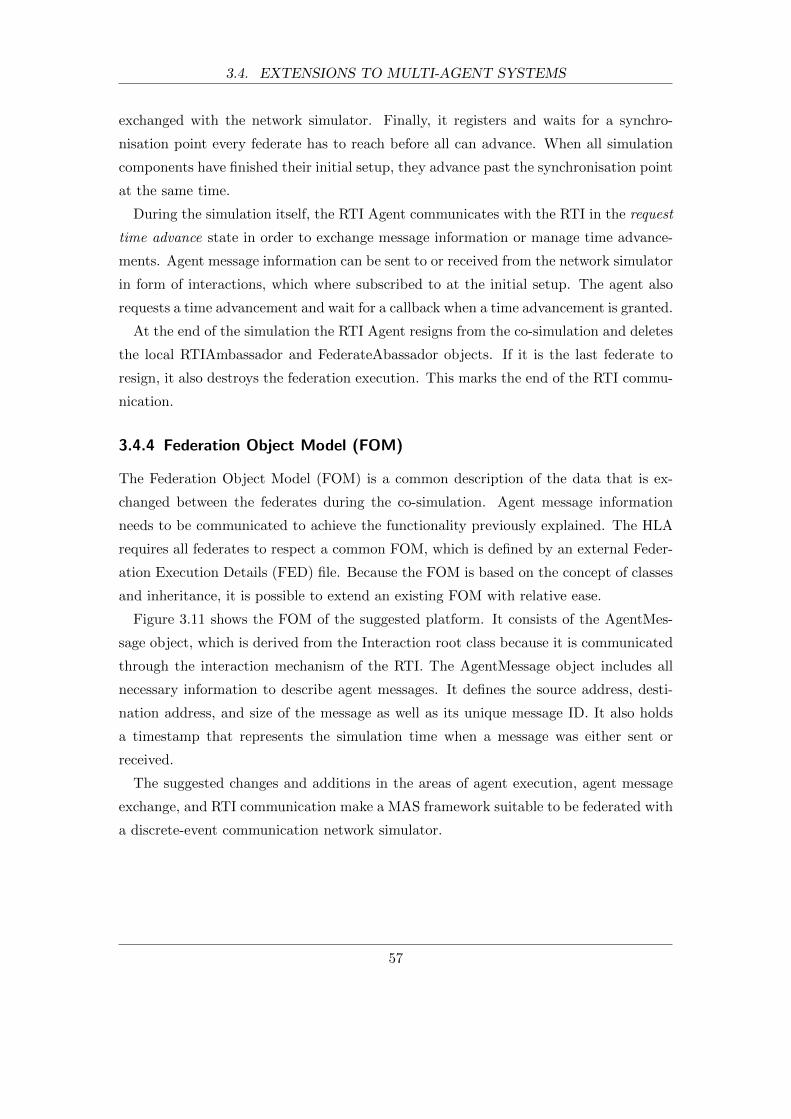
3.4. EXTENSIONS TO MULTI-AGENT SYSTEMS
exchanged with the network simulator. Finally, it registers and waits for a synchro-
nisation point every federate has to reach before all can advance. When all simulation
components have finished their initial setup, they advance past the synchronisation point
at the same time.
During the simulation itself, the RTI Agent communicates with the RTI in the request
time advance state in order to exchange message information or manage time advance-
ments. Agent message information can be sent to or received from the network simulator
in form of interactions, which where subscribed to at the initial setup. The agent also
requests a time advancement and wait for a callback when a time advancement is granted.
At the end of the simulation the RTI Agent resigns from the co-simulation and deletes
the local RTIAmbassador and FederateAbassador objects. If it is the last federate to
resign, it also destroys the federation execution. This marks the end of the RTI commu-
nication.
3.4.4 Federation Object Model (FOM)
The Federation Object Model (FOM) is a common description of the data that is ex-
changed between the federates during the co-simulation. Agent message information
needs to be communicated to achieve the functionality previously explained. The HLA
requires all federates to respect a common FOM, which is defined by an external Feder-
ation Execution Details (FED) file. Because the FOM is based on the concept of classes
and inheritance, it is possible to extend an existing FOM with relative ease.
Figure 3.11 shows the FOM of the suggested platform. It consists of the AgentMes-
sage object, which is derived from the Interaction root class because it is communicated
through the interaction mechanism of the RTI. The AgentMessage object includes all
necessary information to describe agent messages. It defines the source address, desti-
nation address, and size of the message as well as its unique message ID. It also holds
a timestamp that represents the simulation time when a message was either sent or
received.
The suggested changes and additions in the areas of agent execution, agent message
exchange, and RTI communication make a MAS framework suitable to be federated with
a discrete-event communication network simulator.
57
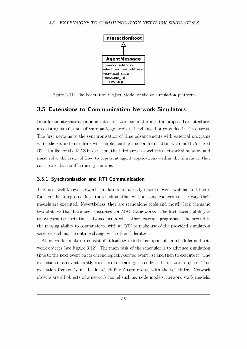
3.5. EXTENSIONS TO COMMUNICATION NETWORK SIMULATORS
Figure 3.11: The Federation Object Model of the co-simulation platform.
3.5 Extensions to Communication Network Simulators
In order to integrate a communication network simulator into the proposed architecture,
an existing simulation software package needs to be changed or extended in three areas.
The first pertains to the synchronisation of time advancements with external programs
while the second area deals with implementing the communication with an HLA-based
RTI. Unlike for the MAS integration, the third area is specific to network simulators and
must solve the issue of how to represent agent applications within the simulator that
can create data traffic during runtime.
3.5.1 Synchronisation and RTI Communication
The most well-known network simulators are already discrete-event systems and there-
fore can be integrated into the co-simulation without any changes to the way their
models are executed. Nevertheless, they are standalone tools and mostly lack the same
two abilities that have been discussed for MAS frameworks. The first absent ability is
to synchronise their time advancements with other external programs. The second is
the missing ability to communicate with an RTI to make use of the provided simulation
services such as the data exchange with other federates.
All network simulators consist of at least two kind of components, a scheduler and net-
work objects (see Figure 3.12). The main task of the scheduler is to advance simulation
time to the next event on its chronologically-sorted event list and then to execute it. The
execution of an event mostly consists of executing the code of the network objects. This
execution frequently results in scheduling future events with the scheduler. Network
objects are all objects of a network model such as, node models, network stack models,
58

3.5. EXTENSIONS TO COMMUNICATION NETWORK SIMULATORS
Figure 3.12: The most basic components of a communication network simulator.
and link models. Figure 3.13 shows the basic flowchart followed by all discrete-event
network simulators.
Figure 3.13: The basic flowchart of any discrete-event network simulator.
In order to synchronise time advancements and communicate with the RTI, a network
simulator can be extended as shown in Figure 3.14. The new HLA Interface component
provides an interface to the runtime infrastructure (RTI) in a similar way the RTI Agent
does for the MAS. It calls standardised methods of the RTIAmbassador object to send
information to the RTI and receives callbacks via the FederateAbassador object.
Internally, it interacts with the event scheduler and network objects. The scheduler
must be modified to request simulation-time advancements through the HLA Interface
and wait for the request to be granted before it can advance and execute the next events.
59
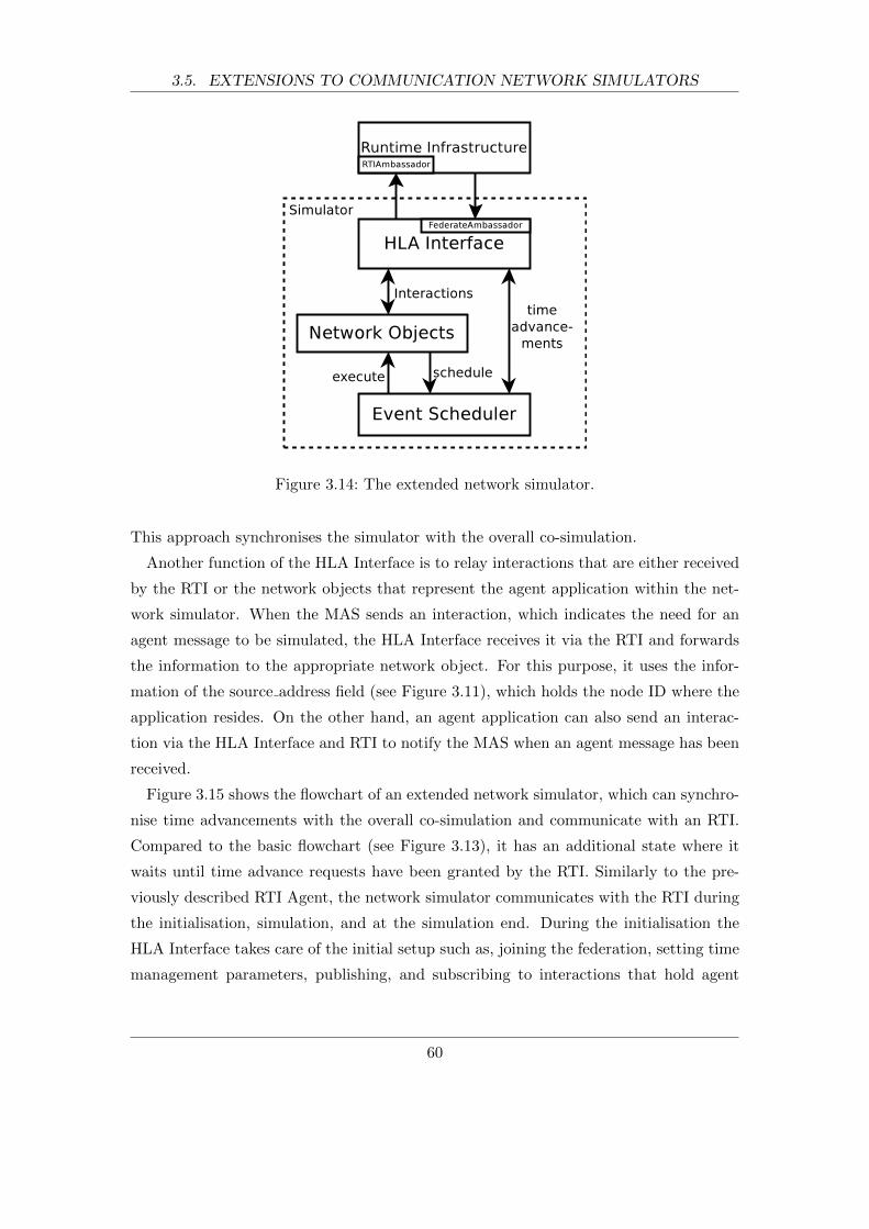
3.5. EXTENSIONS TO COMMUNICATION NETWORK SIMULATORS
Figure 3.14: The extended network simulator.
This approach synchronises the simulator with the overall co-simulation.
Another function of the HLA Interface is to relay interactions that are either received
by the RTI or the network objects that represent the agent application within the net-
work simulator. When the MAS sends an interaction, which indicates the need for an
agent message to be simulated, the HLA Interface receives it via the RTI and forwards
the information to the appropriate network object. For this purpose, it uses the infor-
mation of the source address field (see Figure 3.11), which holds the node ID where the
application resides. On the other hand, an agent application can also send an interac-
tion via the HLA Interface and RTI to notify the MAS when an agent message has been
received.
Figure 3.15 shows the flowchart of an extended network simulator, which can synchro-
nise time advancements with the overall co-simulation and communicate with an RTI.
Compared to the basic flowchart (see Figure 3.13), it has an additional state where it
waits until time advance requests have been granted by the RTI. Similarly to the pre-
viously described RTI Agent, the network simulator communicates with the RTI during
the initialisation, simulation, and at the simulation end. During the initialisation the
HLA Interface takes care of the initial setup such as, joining the federation, setting time
management parameters, publishing, and subscribing to interactions that hold agent
60

3.5. EXTENSIONS TO COMMUNICATION NETWORK SIMULATORS
message information. It also registers to the same synchronisation point as the MAS
and then waits until the RTI instructs all federates that it is safe to advance. During
the main simulation loop the RTI is contacted to request time advancements. The last
communication with the RTI happens at the end of the simulation when the simulator
resigns from the federation.
Figure 3.15: The flowchart of an extended network simulator.
The suggested changes to an existing network simulator are only possible if the source
code is available or it features APIs that allow to control the scheduler. Open source sim-
ulators are the easiest to extend because the behaviour of the scheduler can be changed
and the HLA Interface added. Alternatively, closed source software packages must ex-
pose the necessary APIs so that the proposed functionality can be implemented. Chapter
4.5 shows how to adapt a well established commercial network simulator.
3.5.2 Generic Agent Application
Another issue that needs to be addressed is how to represent the agent application within
a network simulator. In general, an application implements a particular logic and gener-
ates data traffic to be simulated. Most simulation packages already come with popular
client/server applications based on internet technologies, such as File Transport Proto-
col (FTP), Hypertext Transfer Protocol (HTTP), database queries, and voice/video over
61
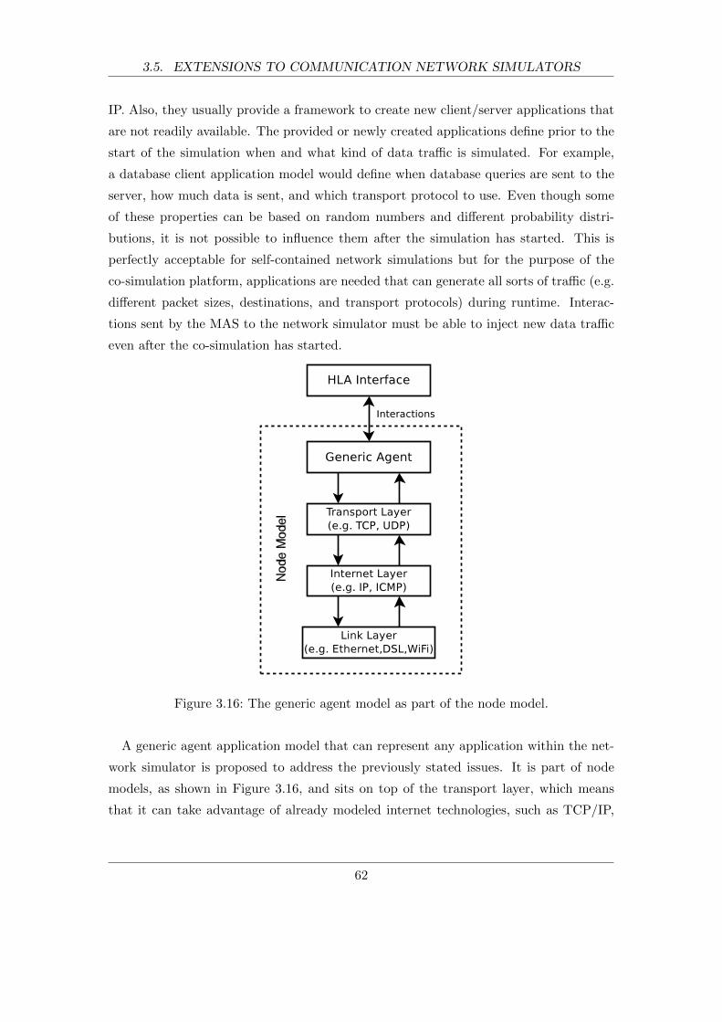
3.5. EXTENSIONS TO COMMUNICATION NETWORK SIMULATORS
IP. Also, they usually provide a framework to create new client/server applications that
are not readily available. The provided or newly created applications define prior to the
start of the simulation when and what kind of data traffic is simulated. For example,
a database client application model would define when database queries are sent to the
server, how much data is sent, and which transport protocol to use. Even though some
of these properties can be based on random numbers and different probability distri-
butions, it is not possible to influence them after the simulation has started. This is
perfectly acceptable for self-contained network simulations but for the purpose of the
co-simulation platform, applications are needed that can generate all sorts of traffic (e.g.
different packet sizes, destinations, and transport protocols) during runtime. Interac-
tions sent by the MAS to the network simulator must be able to inject new data traffic
even after the co-simulation has started.
Figure 3.16: The generic agent model as part of the node model.
A generic agent application model that can represent any application within the net-
work simulator is proposed to address the previously stated issues. It is part of node
models, as shown in Figure 3.16, and sits on top of the transport layer, which means
that it can take advantage of already modeled internet technologies, such as TCP/IP,
62

3.6. SIMULATION EXECUTION AND TIME MANAGEMENT
UDP, ICMP, WiFi, or Ethernet. It is generic in the sense that there is only one model
for all possible agent applications regardless of their function. In essence, it acts as a
generator as well as a sink of data traffic. When it receives an interaction from the
MAS via the HLA Interface, it creates data traffic based on the received payload size,
destination address, and message ID that comes with the interaction (see Figure 3.11).
On the other hand, when a generic agent receives data, it sends a similar interaction
back to the MAS via the HLA Interface. The interaction contains the same message
ID as the interaction that initiated the creation of the received data. This information
enables the MAS to establish which agent message has been received.
The suggested generic agent application gives the MAS the means to create new data
traffic within the network simulator during runtime. The interactions that are exchanged
between the federates serve as a system to exchange agent message information. This
generic approach enables the network modeller to use the exact same agent application
model to represent any agent running in the MAS. This means that the network mod-
eller does not need to be aware of the agent logic and the MAS and network model
development is separated from each other.
3.6 Simulation Execution and Time Management
Having looked at each individual component of the suggested co-simulation platform,
this section explains how the federation is executed as a whole. A simple example is
given to help understand the interaction between all components.
Figure 3.17 shows the individual components in the context of the overall platform
architecture. Communication between components is indicated by arrows and possible
extensions to the suggested platform are shown as dotted lines.
There are several ways the co-simulation platform can be set up. The runtime infras-
tructure (RTI), the MAS platform, and the network simulator are independent compo-
nents and can therefore run together on one computer or on separate networked com-
puters. Because the available computer memory is one of the main limiting factors with
respect to the size of simulation models, it can be advantageous to run the MAS platform
and the network simulator on dedicated computers.
The simulation execution consists of three phases. In the first phase all simulation
components initialise and join the federation. Then, the actual simulation of the MAS
and network models are run in the second phase. On completion, all simulation compo-
63
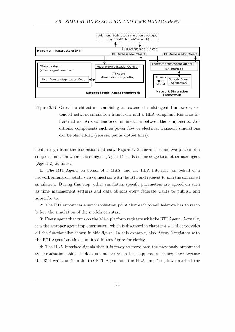
3.6. SIMULATION EXECUTION AND TIME MANAGEMENT
Figure 3.17: Overall architecture combining an extended multi-agent framework, ex-
tended network simulation framework and a HLA-compliant Runtime In-
frastructure. Arrows denote communication between the components. Ad-
ditional components such as power flow or electrical transient simulations
can be also added (represented as dotted lines).
nents resign from the federation and exit. Figure 3.18 shows the first two phases of a
simple simulation where a user agent (Agent 1) sends one message to another user agent
(Agent 2) at time t.
1: The RTI Agent, on behalf of a MAS, and the HLA Interface, on behalf of a
network simulator, establish a connection with the RTI and request to join the combined
simulation. During this step, other simulation-specific parameters are agreed on such
as time management settings and data objects every federate wants to publish and
subscribe to.
2: The RTI announces a synchronisation point that each joined federate has to reach
before the simulation of the models can start.
3: Every agent that runs on the MAS platform registers with the RTI Agent. Actually,
it is the wrapper agent implementation, which is discussed in chapter 3.4.1, that provides
all the functionality shown in this figure. In this example, also Agent 2 registers with
the RTI Agent but this is omitted in this figure for clarity.
4: The HLA Interface signals that it is ready to move past the previously announced
synchronisation point. It does not matter when this happens in the sequence because
the RTI waits until both, the RTI Agent and the HLA Interface, have reached the
64
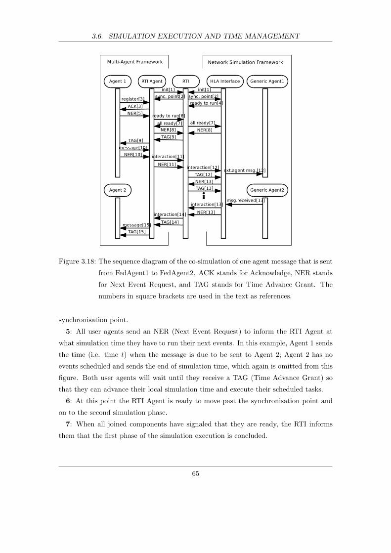
3.6. SIMULATION EXECUTION AND TIME MANAGEMENT
Figure 3.18: The sequence diagram of the co-simulation of one agent message that is sent
from FedAgent1 to FedAgent2. ACK stands for Acknowledge, NER stands
for Next Event Request, and TAG stands for Time Advance Grant. The
numbers in square brackets are used in the text as references.
synchronisation point.
5: All user agents send an NER (Next Event Request) to inform the RTI Agent at
what simulation time they have to run their next events. In this example, Agent 1 sends
the time (i.e. time t) when the message is due to be sent to Agent 2; Agent 2 has no
events scheduled and sends the end of simulation time, which again is omitted from this
figure. Both user agents will wait until they receive a TAG (Time Advance Grant) so
that they can advance their local simulation time and execute their scheduled tasks.
6: At this point the RTI Agent is ready to move past the synchronisation point and
on to the second simulation phase.
7: When all joined components have signaled that they are ready, the RTI informs
them that the first phase of the simulation execution is concluded.
65

3.6. SIMULATION EXECUTION AND TIME MANAGEMENT
8: Next, they send an NER to request an advancement in simulation time. Because
all agents have sent their NERs to the RTI Agent, it knows when the next event is
due. Likewise, the HLA Interface, which has access to the event list of the network
simulation scheduler, also requests an NER. For this example, the RTI Agent requests
a time advance to the time when Agent 1 is scheduled to send the message to Agent 2.
The HLA Interface would request to advance time to the network simulator’s next event
but in this example it is assumed that there are no scheduled events and it requests to
advance to the simulation end time.
9: With the NERs from the RTI Agent and HLA Interface, the RTI can decide which
component has to run next and announces a TAG (Time Advance Grant) to the RTI
Agent. The RTI Agent advances its local simulation time and executes the due event,
which results in a TAG message sent to Agent 1.
10: Agent 1 is now allowed to also advance its local simulation time and execute the
task for the current time, which sends a message to Agent 2. This message is not directly
delivered to Agent 2 but sent to the RTI Agent followed by a new NER. The new NER
requests a time advance to the end of the simulation since there are no other tasks Agent
1 has to carry out.
11: The RTI Agent stores the agent message and sends an interaction message that
contains the sender, the receiver, the size, a time-stamp, and an ID of the agent message.
This is followed by an NER indicating that there are no future events until the end of
the simulation.
12: The RTI forwards the interaction message to the HLA Interface and grants a time
advance by sending a TAG in order for the network simulation to react to the message.
The HLA Interface forwards the interaction, which instructs the Generic Agent 1 to
create the new traffic that represents the agent message within the network simulation.
13: Because the accurate simulation of data traffic is made up of several events, the
HLA Interface has to advance its simulation time step by step until the data transfer
from Generic Agent 1 to Generic Agent 2 is complete. This might result in several NER
and TAG messages (represented by three). Upon completion, the Generic Agent 2 sends
a message to the HLA Interface which is forwarded in form of an interaction message to
the RTI. This interaction contains the ID of the transfered message. The HLA Interface
also sends another NER to request a time advance to the end of the simulation.
14: The RTI forwards the interaction received from the HLA Interface and grants
time to the RTI Agent to be able to respond to the interaction.
66
3.6. SIMULATION EXECUTION AND TIME MANAGEMENT
15: When the RTI Agent receives the interaction, it looks up the stored agent message
by means of its ID and schedules a message event which is executed after the TAG has
been received. The execution of the message event results in the delivery of the original
agent message to Agent 2 and a TAG so that the agent can react to this event if necessary.
From this simple example, it can be seen how the simulation platform manages time
synchronisation at the start and throughout the simulation. The synchronisation points
ensure that all components start at the same time in a controlled manner. The NER
and TAG messages guarantee that all events across the whole platform are executed in
the correct order and all causal relationships are maintained.
A conservative time management approach with variable time intervals was chosen for
this discrete-event co-simulation. The federates are based on next-event time advance-
ments (variable time intervals) as opposed to fixed-time advancements. Also, the overall
co-simulation is synchronous, which means that only one event is executed at any given
time and no parallel execution is allowed. This is called a conservative time management
approach. It was chosen over a more optimistic (e.g. time warp) and hybrid approaches
(e.g. [99]), which allow a more parallel event execution, because the strong link between
the federates would cause frequent causality violations. These would then trigger expen-
sive roll back operations, which require large amounts of computer memory and make
the simulation execution significantly more complex. Also, as Fujimoto [100] states, the
HLA was not designed with parallel simulations in mind.
As mentioned earlier, the HLA standard requires every federate to inform the RTI dur-
ing initialisation what degree of involvement it has in terms of time management. Both
federates set their involvement to time-regulating and time-constrained, which guaran-
tees that they are fully time synchronised and no federate can run ahead of the rest of
the federation.
Another parameter that the RTI must know about every joined federate is the looka-
head value. It is a positive number that defines the time every time-regulating federate
has to look ahead of its current simulation time for all services provided by the RTI.
For example, consider a federate that has just advanced to the time t. The RTI will
not accept any interactions or time advance requests for times less than t+ lookahead.
This is necessary to avoid deadlocks for simulation with a conservative synchronisation
approach. If federates were allowed to send interactions at the current time t, no federate
could advance its simulation time because the RTI would not risk to deliver interactions
in the past. This would result in a deadlock situation. More information on the theory
67
3.7. SUMMARY
behind time management techniques can be found in [97] and [100].
For the proposed co-simulation platform, the lookahead governs how quickly one fed-
erate can react to an interaction of another federate. This time to react introduces
unwanted delays that are added to the simulated communications delays and therefore
the lookahead value should be kept small. The actual value depends on the simulated
models and the accuracy that one wants to achieve. For example, the case study de-
scribed later uses 1µs.
3.7 Summary
This chapter described the challenges of co-simulating multi-agent systems and network
simulators and presented a generic design of a platform that can overcome them. The
design suggested specific extensions to be made to multi-agent systems and network
simulators.
Multi-agent systems were extended by additional agents to provide agent message
management and discrete-event capabilities. The discussed agent message management
would allow to redirect message transport and to share message information with net-
work simulators. The discrete-event capabilities that would be achieved by controlling
the execution of agents’ task, would make time synchronisation with discrete-event sim-
ulators possible.
Network simulators were suggested to be extended by a generic application model.
This model would represent any agent application within a network simulation and
could inject any kind of data traffic into the simulation at runtime. It would also add
the support to exchange information with its associated agents in the MAS.
Apart from these extensions, the design included a runtime-environment (RTI), which
would provide distributed simulation modelling services, such as platform-wide time
management and a means to exchange data between federates. It would be based on a
standardised interface to open the possibility for the integration of other tools.
The next chapter applies the presented design to implement a co-simulation platform.
68
4 MAC-Sim Platform Implementation
4.1 Introduction
This chapter presents the implementation of the previously introduced platform archi-
tecture. The platform is called MAC-Sim, which stands for Multi-Agent and Commu-
nication Simulator. MAC-Sim allows for a discrete-event co-simulation of agents that
are modeled with the Java Agent DEvelopment Framework (JADE [24]), and network
models that are created with OPNET Modeler [69]. This enables developers to accu-
rately study multi-agent systems while taking their communication infrastructure into
account.
The next sections discuss in detail what changes and additions have been made to
JADE and OPNET in order to build the platform. They were realized using strategies
of re-implementation, extension of intermediate code, and usage of external APIs as
discussed by Straburger [82].
4.2 Platform Overview
Figure 4.1 shows all components that make up the MAC-Sim platform. The HLA-based
runtime infrastructure (RTI) is provided by MAK RTI [101]. Agents are modeled with
the Java Agent DEvelopment Framework (JADE), which is federated with the network
simulator OPNET Modeler. The platform also includes two global files that can be
accessed by all components. The agent-node mapping file consists of a table of agent
IDs and their corresponding node IDs. For the example models in Figure 4.1, the table
would map agent A1 to node N1 and agent A2 to node N2 and so forth. Because these
mappings can be easily changed, agents can be deployed on different nodes without
making any changes to the models themselves. The second global file is the Federation
Execution Details (FED) file. The FED file implements the Federation Object Model
(FOM) (see Figure 3.11) as discussed in section 3.4.4, which defines the data the federates
69
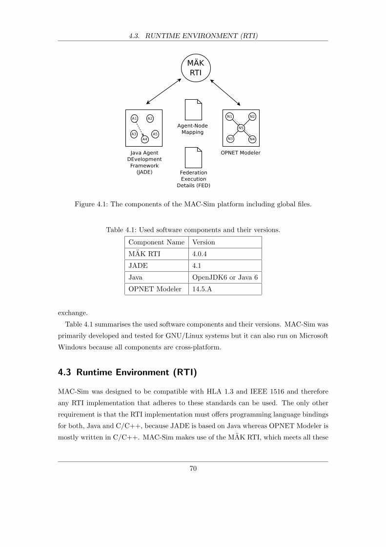
4.3. RUNTIME ENVIRONMENT (RTI)
Figure 4.1: The components of the MAC-Sim platform including global files.
Table 4.1: Used software components and their versions.
Component Name Version
MAK RTI 4.0.4
JADE 4.1
Java OpenJDK6 or Java 6
OPNET Modeler 14.5.A
exchange.
Table 4.1 summarises the used software components and their versions. MAC-Sim was
primarily developed and tested for GNU/Linux systems but it can also run on Microsoft
Windows because all components are cross-platform.
4.3 Runtime Environment (RTI)
MAC-Sim was designed to be compatible with HLA 1.3 and IEEE 1516 and therefore
any RTI implementation that adheres to these standards can be used. The only other
requirement is that the RTI implementation must offers programming language bindings
for both, Java and C/C++, because JADE is based on Java whereas OPNET Modeler is
mostly written in C/C++. MAC-Sim makes use of the MAK RTI, which meets all these
70
4.4. JAVA AGENT DEVELOPMENT INTEGRATION
requirements. MAK RTI also includes diagnostic utilities that help with debugging a
federation.
No changes were necessary to MAK RTI except for setting configuration parameters
related to the communication with the federates. For example, the RTI communication
can be set to reliable or unreliable communication. Reliable communication is slower
but ensures that no data is lost. This is achieved by acknowledging the receipt of data
or retransmitting lost data, which adds overhead to the protocol. On the other hand,
unreliable communication does not have this overhead and is therefore faster. Obviously,
the faster the RTI communication, the faster the co-simulation runs. Thus, the unreliable
communication mode is preferred if all MAC-Sim components are deployed on the same
computer or the utilised communication network is dedicated for the simulation and
does not carry any other data traffic it could interfere with.
Another communication mode that is supported by MAK RTI is to utilise memory
sharing instead of network-based RTI communication. This requires that all MAC-
Sim components run on the same computer but is by far the best performing option.
However, this mode is not HLA-compliant and was not tested with the platform.
As mentioned before, any HLA-compliant RTI implementation can be used. In fact,
MAC-Sim only relies on a subset of the standardised interface, which means that it can
also run with an RTI that does not implement the full HLA specification. The lists of
required services can be found in the Appendix 7.1.
MAK RTI is a commercial product and open-source RTI implementations exist, such
as the Portico project [102] and CERTI [103]. Both partly implement the HLA 1.3 and
IEEE 1516 standard and provide Java and C++ language bindings. Portico version 1.0.2
and CERTI version 3.4.0 were tested with MAC-Sim but could not be used because
a few RTI services were not found to behave according to the specifications. More
specifically, some time management services (e.g. nextEventRequest) were not properly
implemented in Portico and minor issues were encountered with synchronisation point
services in CERTI. However, once these issues have been dealt with, both projects could
serve as a suitable replacement.
4.4 Java Agent DEvelopment Integration
The Java Agent DEvelopment (JADE) framework [24] is an open-source framework that
supports the development of multi-agent systems (MAS). It is fully written in Java and
71

4.4. JAVA AGENT DEVELOPMENT INTEGRATION
is FIPA-compliant [19]. Thus, it implements concepts of FIPA such as the agent plat-
form, directory facilitator, and message transport service. The agent platform provides
a runtime environment and physical infrastructure in which agents can be deployed.
The directory facilitator offers a yellow pages service and the message transport service
provides the transport of messages between agents. All these concepts and functionali-
ties are exposed as rich application programming interfaces (APIs) to the agent model
developers. JADE also comes with a set of graphical tools that support debugging and
deployment.
There are a great number of other MAS development toolkits available that could
have been adopted instead of JADE. Allan [18] published an extensive list of tools
and previous research [27, 28, 29, 30] evaluated some of them. JADE was chosen for
several reasons. Firstly, it is one of only few tools that conform to FIPA’s standards
and is publicly available [23]. Standards are significant and ensure the interoperability
between MAS that were developed with different toolkits and run on different platforms.
Secondly, it provides a runtime environment in which the developed multi-agents can be
deployed. In contrast, some tools only support the modelling of agents for the purpose
of simulations, which cannot be deployed. Thirdly, JADE scales well to large systems
with many agents. [104] tested the efficiency of the JADE platform with respect to
large systems and their tests indicate that it is an efficient environment that is mostly
limited by the limitations of the Java programming language. Another reason to federate
JADE is that it supports agent-oriented software engineering. For example, it offers the
concepts of behaviours as a software abstraction for tasks that agents carry out. Finally,
JADE seems to be popular among researchers. According to [36] it has become a firm
favourite with researchers in power engineering. [105], [9], [4], [89], [13], [11], are just
some examples of research where JADE was used.
4.4.1 Development in JADE
In order to help explain how JADE was integrated with the overall MAC-Sim platform, a
summary of how agent models are created and how they are executed is provided below.
A new agent is created by writing a new Java class that extends the existing Jade.core.Agent
class, which is part of JADE. This new class usually implements the two methods setup()
and takeDown(). setup() is run once when the agent is started by the agent platform
whereas takeDown() is run just before the agent dies. In order for the agents to carry out
72
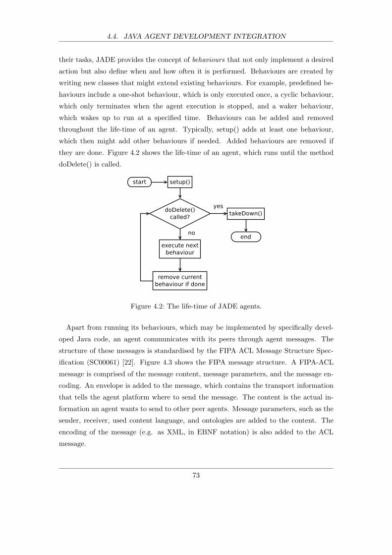
4.4. JAVA AGENT DEVELOPMENT INTEGRATION
their tasks, JADE provides the concept of behaviours that not only implement a desired
action but also define when and how often it is performed. Behaviours are created by
writing new classes that might extend existing behaviours. For example, predefined be-
haviours include a one-shot behaviour, which is only executed once, a cyclic behaviour,
which only terminates when the agent execution is stopped, and a waker behaviour,
which wakes up to run at a specified time. Behaviours can be added and removed
throughout the life-time of an agent. Typically, setup() adds at least one behaviour,
which then might add other behaviours if needed. Added behaviours are removed if
they are done. Figure 4.2 shows the life-time of an agent, which runs until the method
doDelete() is called.
Figure 4.2: The life-time of JADE agents.
Apart from running its behaviours, which may be implemented by specifically devel-
oped Java code, an agent communicates with its peers through agent messages. The
structure of these messages is standardised by the FIPA ACL Message Structure Spec-
ification (SC00061) [22]. Figure 4.3 shows the FIPA message structure. A FIPA-ACL
message is comprised of the message content, message parameters, and the message en-
coding. An envelope is added to the message, which contains the transport information
that tells the agent platform where to send the message. The content is the actual in-
formation an agent wants to send to other peer agents. Message parameters, such as the
sender, receiver, used content language, and ontologies are added to the content. The
encoding of the message (e.g. as XML, in EBNF notation) is also added to the ACL
message.
73
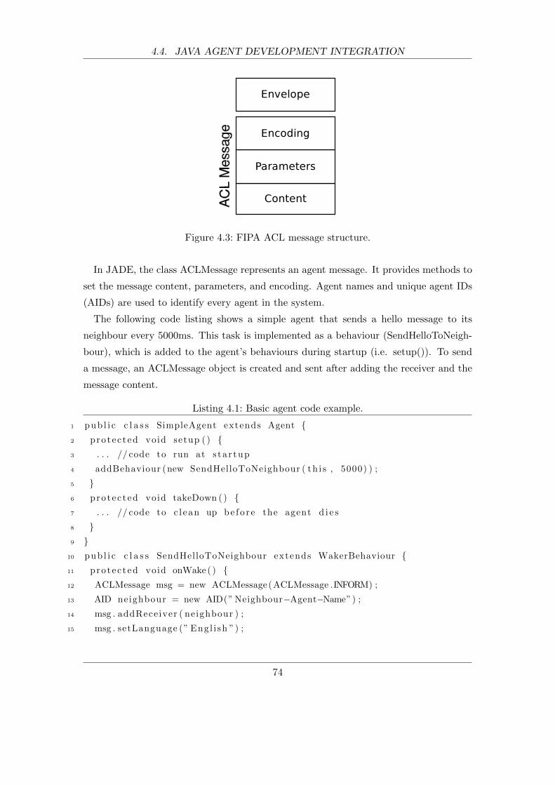
4.4. JAVA AGENT DEVELOPMENT INTEGRATION
Figure 4.3: FIPA ACL message structure.
In JADE, the class ACLMessage represents an agent message. It provides methods to
set the message content, parameters, and encoding. Agent names and unique agent IDs
(AIDs) are used to identify every agent in the system.
The following code listing shows a simple agent that sends a hello message to its
neighbour every 5000ms. This task is implemented as a behaviour (SendHelloToNeigh-
bour), which is added to the agent’s behaviours during startup (i.e. setup()). To send
a message, an ACLMessage object is created and sent after adding the receiver and the
message content.
Listing 4.1: Basic agent code example.
1 pub l i c c l a s s SimpleAgent extends Agent {2 protec ted void setup ( ) {3 . . . // code to run at s ta r tup
4 addBehaviour (new SendHelloToNeighbour ( th i s , 5000) ) ;
5 }6 protec ted void takeDown ( ) {7 . . . // code to c l ean up be f o r e the agent d i e s
8 }9 }
10 pub l i c c l a s s SendHelloToNeighbour extends WakerBehaviour {11 protec ted void onWake ( ) {12 ACLMessage msg = new ACLMessage (ACLMessage .INFORM) ;
13 AID neighbour = new AID(” Neighbour−Agent−Name”) ;
14 msg . addReceiver ( neighbour ) ;
15 msg . setLanguage (” Engl i sh ”) ;
74
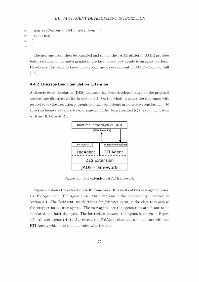
4.4. JAVA AGENT DEVELOPMENT INTEGRATION
16 msg . setContent (” He l lo neighbour ! ” ) ;
17 send (msg) ;
18 }19 }
The new agent can then be compiled and run on the JADE platform. JADE provides
both, a command line and a graphical interface, to add new agents to an agent platform.
Developers who want to know more about agent development in JADE should consult
[106].
4.4.2 Discrete-Event Simulation Extension
A discrete-event simulation (DES) extension has been developed based on the proposed
architecture discussed earlier in section 3.4. On the whole, it solves the challenges with
respect to (a) the execution of agents and their behaviours in a discrete-event fashion, (b)
time synchronisation and data exchange with other federates, and (c) the communication
with an HLA-based RTI.
Figure 4.4: The extended JADE framework.
Figure 4.4 shows the extended JADE framework. It consists of two new agent classes,
the FedAgent and RTI Agent class, which implement the functionality described in
section 3.4. The FedAgent, which stands for federated agent, is the class that acts as
the wrapper for all user agents. The user agents are the agents that are meant to be
simulated and later deployed. The interaction between the agents is shown in Figure
4.5. All user agents (A1 to An) extend the FedAgent class and communicate with one
RTI Agent, which also communicates with the RTI.
75
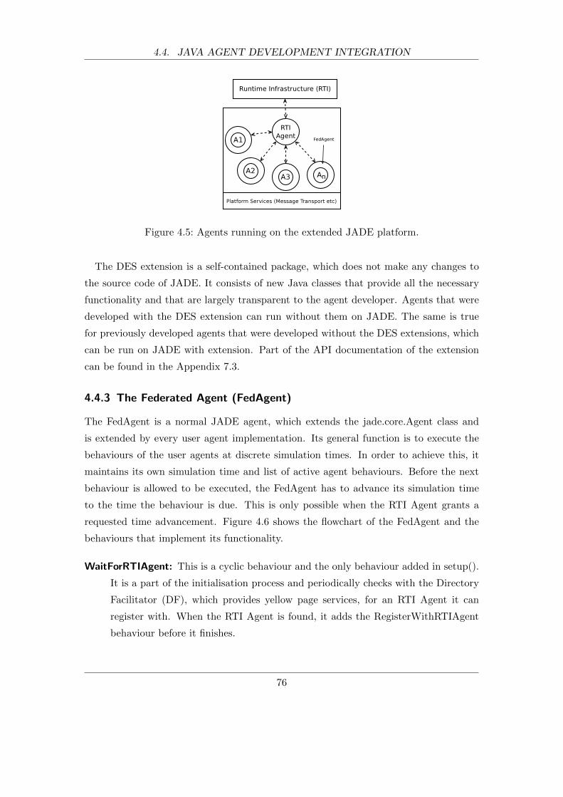
4.4. JAVA AGENT DEVELOPMENT INTEGRATION
Figure 4.5: Agents running on the extended JADE platform.
The DES extension is a self-contained package, which does not make any changes to
the source code of JADE. It consists of new Java classes that provide all the necessary
functionality and that are largely transparent to the agent developer. Agents that were
developed with the DES extension can run without them on JADE. The same is true
for previously developed agents that were developed without the DES extensions, which
can be run on JADE with extension. Part of the API documentation of the extension
can be found in the Appendix 7.3.
4.4.3 The Federated Agent (FedAgent)
The FedAgent is a normal JADE agent, which extends the jade.core.Agent class and
is extended by every user agent implementation. Its general function is to execute the
behaviours of the user agents at discrete simulation times. In order to achieve this, it
maintains its own simulation time and list of active agent behaviours. Before the next
behaviour is allowed to be executed, the FedAgent has to advance its simulation time
to the time the behaviour is due. This is only possible when the RTI Agent grants a
requested time advancement. Figure 4.6 shows the flowchart of the FedAgent and the
behaviours that implement its functionality.
WaitForRTIAgent: This is a cyclic behaviour and the only behaviour added in setup().
It is a part of the initialisation process and periodically checks with the Directory
Facilitator (DF), which provides yellow page services, for an RTI Agent it can
register with. When the RTI Agent is found, it adds the RegisterWithRTIAgent
behaviour before it finishes.
76

4.4. JAVA AGENT DEVELOPMENT INTEGRATION
Figure 4.6: The flowchart of the FedAgent and the behaviours that implement it.
RegisterWithRTIAgent: This one-shot behaviour does the actual initialisation, which
includes registering with the RTI Agent, initialising the behaviour list, and sending
the first Next Event Request (NER) to the RTI Agent. The FedAgent registers
so that the RTI Agent knows that the agent is part of the simulation. During
registration the current simulation time, which is 0 unless the agent joins in the
middle of a running co-simulation, and the simulation end time is defined. Also,
the RTI Agent sends the value for the lookahead (discussed earlier in section 3.6),
which is the same for the whole co-simulation. This behaviour then creates the
initial list of user agent behaviours, which is sorted by due times, and adds the
Kernel behaviour before it exits.
Kernel: The cyclic Kernel behaviour carries out the main tasks and runs until the sim-
ulation ends. It sends Next Event Requests (NER) to the RTI Agent and receives
time advance grants (TAG) in order to advance its simulation time and then exe-
cute the next user agent behaviours. After executing all behaviours for the current
simulation time, the behaviour list has to be updated. This is necessary because
behaviours can finish but also new behaviours can be added. The Kernel finishes
when the simulation time reaches the previously set simulation end time.
For the FedAgent to function as explained, new behaviour classes had to be imple-
mented. In JADE, user agents’ behaviours only take a time duration as an argument to
77
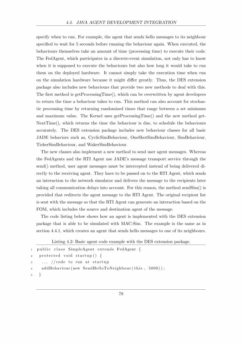
4.4. JAVA AGENT DEVELOPMENT INTEGRATION
specify when to run. For example, the agent that sends hello messages to its neighbour
specified to wait for 5 seconds before running the behaviour again. When executed, the
behaviours themselves take an amount of time (processing time) to execute their code.
The FedAgent, which participates in a discrete-event simulation, not only has to know
when it is supposed to execute the behaviours but also how long it would take to run
them on the deployed hardware. It cannot simply take the execution time when run
on the simulation hardware because it might differ greatly. Thus, the DES extension
package also includes new behaviours that provide two new methods to deal with this.
The first method is getProcessingTime(), which can be overwritten by agent developers
to return the time a behaviour takes to run. This method can also account for stochas-
tic processing time by returning randomized times that range between a set minimum
and maximum value. The Kernel uses getProcessingTime() and the new method get-
NextTime(), which returns the time the behaviour is due, to schedule the behaviours
accurately. The DES extension package includes new behaviour classes for all basic
JADE behaviors such as, CyclicSimBehaviour, OneShotSimBehaviour, SimBehaviour,
TickerSimBehaviour, and WakerSimBehaviour.
The new classes also implement a new method to send user agent messages. Whereas
the FedAgents and the RTI Agent use JADE’s message transport service through the
send() method, user agent messages must be intercepted instead of being delivered di-
rectly to the receiving agent. They have to be passed on to the RTI Agent, which sends
an interaction to the network simulator and delivers the message to the recipients later
taking all communication delays into account. For this reason, the method sendSim() is
provided that redirects the agent message to the RTI Agent. The original recipient list
is sent with the message so that the RTI Agent can generate an interaction based on the
FOM, which includes the source and destination agent of the message.
The code listing below shows how an agent is implemented with the DES extension
package that is able to be simulated with MAC-Sim. The example is the same as in
section 4.4.1, which creates an agent that sends hello messages to one of its neighbours.
Listing 4.2: Basic agent code example with the DES extension package.
1 pub l i c c l a s s SimpleAgent extends FedAgent {2 protec ted void s ta r tup ( ) {3 . . . // code to run at s ta r tup
4 addBehaviour (new SendHelloToNeighbour ( th i s , 5000) ) ;
5 }
78
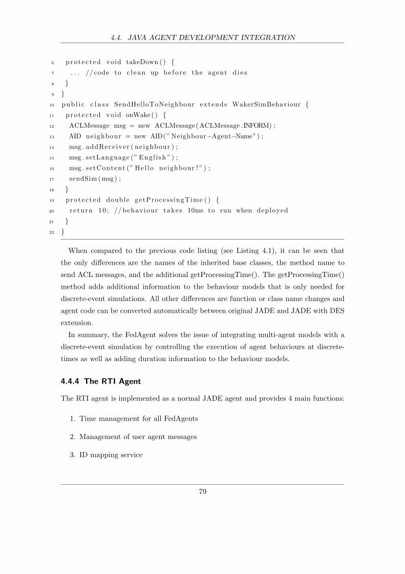
4.4. JAVA AGENT DEVELOPMENT INTEGRATION
6 protec ted void takeDown ( ) {7 . . . // code to c l ean up be f o r e the agent d i e s
8 }9 }
10 pub l i c c l a s s SendHelloToNeighbour extends WakerSimBehaviour {11 protec ted void onWake ( ) {12 ACLMessage msg = new ACLMessage (ACLMessage .INFORM) ;
13 AID neighbour = new AID(” Neighbour−Agent−Name”) ;
14 msg . addReceiver ( neighbour ) ;
15 msg . setLanguage (” Engl i sh ”) ;
16 msg . setContent (” He l lo neighbour ! ” ) ;
17 sendSim (msg) ;
18 }19 protec ted double getProcess ingTime ( ) {20 re turn 10 ; // behaviour takes 10ms to run when deployed
21 }22 }
When compared to the previous code listing (see Listing 4.1), it can be seen that
the only differences are the names of the inherited base classes, the method name to
send ACL messages, and the additional getProcessingTime(). The getProcessingTime()
method adds additional information to the behaviour models that is only needed for
discrete-event simulations. All other differences are function or class name changes and
agent code can be converted automatically between original JADE and JADE with DES
extension.
In summary, the FedAgent solves the issue of integrating multi-agent models with a
discrete-event simulation by controlling the execution of agent behaviours at discrete-
times as well as adding duration information to the behaviour models.
4.4.4 The RTI Agent
The RTI agent is implemented as a normal JADE agent and provides 4 main functions:
1. Time management for all FedAgents
2. Management of user agent messages
3. ID mapping service
79
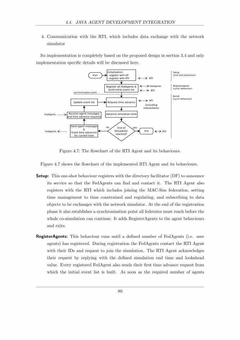
4.4. JAVA AGENT DEVELOPMENT INTEGRATION
4. Communication with the RTI, which includes data exchange with the network
simulator
Its implementation is completely based on the proposed design in section 3.4 and only
implementation specific details will be discussed here.
Figure 4.7: The flowchart of the RTI Agent and its behaviours.
Figure 4.7 shows the flowchart of the implemented RTI Agent and its behaviours.
Setup: This one-shot behaviour registers with the directory facilitator (DF) to announce
its service so that the FedAgents can find and contact it. The RTI Agent also
registers with the RTI which includes joining the MAC-Sim federation, setting
time management to time constrained and regulating, and subscribing to data
objects to be exchanges with the network simulator. At the end of the registration
phase it also establishes a synchronisation point all federates must reach before the
whole co-simulation can continue. It adds RegisterAgents to the agent behaviours
and exits.
RegisterAgents: This behaviour runs until a defined number of FedAgents (i.e. user
agents) has registered. During registration the FedAgents contact the RTI Agent
with their IDs and request to join the simulation. The RTI Agent acknowledges
their request by replying with the defined simulation end time and lookahead
value. Every registered FedAgent also sends their first time advance request from
which the initial event list is built. As soon as the required number of agents
80

4.4. JAVA AGENT DEVELOPMENT INTEGRATION
have registered, the RTI is notified that the synchronisation point was reached. As
the last step, the Kernel behaviour is added, which concludes the life-time of this
behaviour.
Kernel: This is the main behaviour of the agent and runs until the end of the co-
simulation. It request a time advance so that it can execute the next event on
its event list. If an advance is granted, it advances simulation time and executes
all events for the current time. As already described, these events can either be a
time advance grant (TAG) event, which sends a TAG to the associated FedAgent
or a message event, which results in the delivery of an agent message that was
intercepted and stored earlier. A message event is always coupled with TAG event
but TAG events can occur on their own. After every event execution the RTI
Agent receives new intercepted agent messages, which are optional, and a new
time advance request. After updating the event list the cycle starts again. Newly
intercepted and stored agent messages trigger an interaction that is send to the
network simulator before the RTI is asked for a new time advance. Similarly, the
RTI Agent might receive an interaction when a new time advance grant is received
from the RTI.
In order to be able to communicate with the RTI, the RTI Agent uses the RTIAmbas-
sador class for outgoing and the DESJadeAmbassador class for incoming communication.
The RTIAmbassador was provided by MAK RTI whereas the DESJadeAmbassador was
developed for MAC-Sim and is part of the DES extension package. Both classes expose
interfaces that are defined by the HLA standard.
The RTI Agent provides a mapping service, which translates between agent IDs in
JADE and network node IDs in OPNET. It is necessary to convert between these IDs
whenever interactions are exchanged. Before the RTI Agent sends an interaction, which
contains the source and destination address of the agent message (see Figure 3.11) it
converts the agent IDs into node IDs OPNET can understand. On the other hand, when
it receives an interaction, the addresses contain node IDs and need to be converted back
to agent IDs. The translation table is read from the global agent-node mapping file.
The RTI Agent can also be run without the RTI and the network simulator for de-
bugging purposes. The mode disables all communication with the RTI and simulation
time can advance without restrictions. A fixed virtual communication delay for agent
messages can be defined. If none of the user agents contains any randomised behaviours,
81
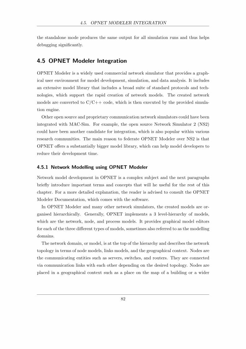
4.5. OPNET MODELER INTEGRATION
the standalone mode produces the same output for all simulation runs and thus helps
debugging significantly.
4.5 OPNET Modeler Integration
OPNET Modeler is a widely used commercial network simulator that provides a graph-
ical user environment for model development, simulation, and data analysis. It includes
an extensive model library that includes a broad suite of standard protocols and tech-
nologies, which support the rapid creation of network models. The created network
models are converted to C/C++ code, which is then executed by the provided simula-
tion engine.
Other open source and proprietary communication network simulators could have been
integrated with MAC-Sim. For example, the open source Network Simulator 2 (NS2)
could have been another candidate for integration, which is also popular within various
research communities. The main reason to federate OPNET Modeler over NS2 is that
OPNET offers a substantially bigger model library, which can help model developers to
reduce their development time.
4.5.1 Network Modelling using OPNET Modeler
Network model development in OPNET is a complex subject and the next paragraphs
briefly introduce important terms and concepts that will he useful for the rest of this
chapter. For a more detailed explanation, the reader is advised to consult the OPNET
Modeler Documentation, which comes with the software.
In OPNET Modeler and many other network simulators, the created models are or-
ganised hierarchically. Generally, OPNET implements a 3 level-hierarchy of models,
which are the network, node, and process models. It provides graphical model editors
for each of the three different types of models, sometimes also referred to as the modelling
domains.
The network domain, or model, is at the top of the hierarchy and describes the network
topology in terms of node models, links models, and the geographical context. Nodes are
the communicating entities such as servers, switches, and routers. They are connected
via communication links with each other depending on the desired topology. Nodes are
placed in a geographical context such as a place on the map of a building or a wider
82

4.5. OPNET MODELER INTEGRATION
geographical region. An example of a network model of an open work space with 8
workstations can be found in Figure 4.8.
Figure 4.8: A network model of 8 workstations.
The node domain, or model, describes communicating entities in terms of their func-
tional elements and data flow between them. They are made up of smaller building
blocks that are called modules, which are connected through connections. The modules
use processes to execute their tasks. It is important to distinguish between a model
(e.g. a node model) and an instance of it (e.g. a node). There can be many instances
of a model with their individual properties and states during simulation. This concept
can be compared to a class definition in computer programming and the objects of that
class. Figure 4.9 shows the node model of one of the workstations. The model is made
up of modules that describe the application and the communication stack for TCP/IP
over Ethernet.
The lowest level in the hierarchy are process models. They describe the behaviour of
modules such as protocols, applications, and algorithms, using finite state machines and
high-level programming languages. The instances of process models are called processes
and respond to interrupts and invocations initiated by the simulation engine. When
a process is executed via an interrupt or invocation it runs until it returns, invokes
another process, or interrupts another process. Various mechanism are provided to pass
data objects between processes with interrupts and invocations. An example of a process
model is shown in Figure 4.10, which is the main process model of the TCP module.
83

4.5. OPNET MODELER INTEGRATION
Figure 4.9: The node model of a workstation and its modules.
4.5.2 Extended OPNET Modeler
Two new components have been developed in order to integrate OPNET Modeler with
MAC-Sim. Figure 4.11 shows the components of the extended simulator. The new
HLA Interface and the Generic Agent Model solve the issues of synchronisation, RTI
communication, and agent application representation with respect to the overall co-
simulation. They are based on the proposed design discussed in chapter 3.5.
4.5.3 HLA Interface
The HLA Interface is implemented as a node model. It consists of one module, which
contains one process model with only one state. OPNET Modeler exposes APIs to inter-
face with external simulation entities and the process model makes use of this feature. It
implements provided interfaces to communicate with the RTI. The three main methods
are the publishAndSubscribe, receiveInteraction, and sendInteraction. The publishAnd-
Subscribe is called during initialisation when the simulation starts and informs the RTI
that it will send and receive interactions that represent the FOM of the co-simulation
platform.
The receiveInteraction method is called whenever an interaction is received from the
RTI. A received interaction means that a agent message transfer needs to be simulated
84
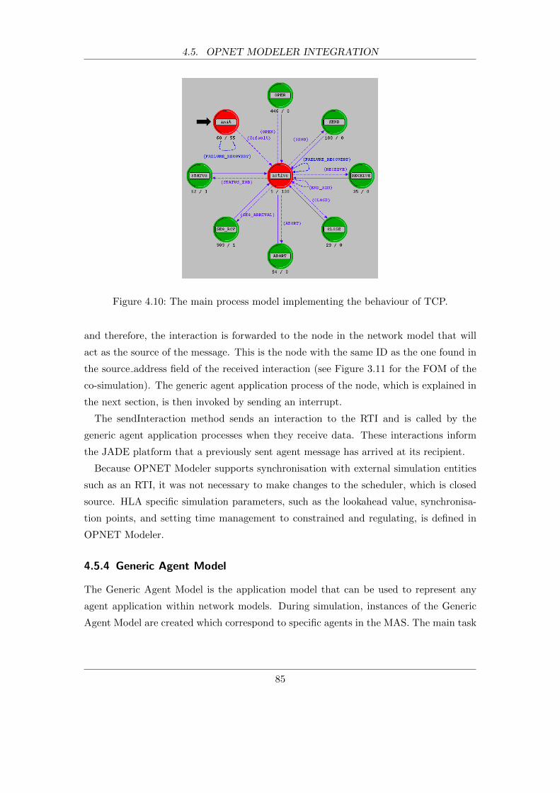
4.5. OPNET MODELER INTEGRATION
Figure 4.10: The main process model implementing the behaviour of TCP.
and therefore, the interaction is forwarded to the node in the network model that will
act as the source of the message. This is the node with the same ID as the one found in
the source address field of the received interaction (see Figure 3.11 for the FOM of the
co-simulation). The generic agent application process of the node, which is explained in
the next section, is then invoked by sending an interrupt.
The sendInteraction method sends an interaction to the RTI and is called by the
generic agent application processes when they receive data. These interactions inform
the JADE platform that a previously sent agent message has arrived at its recipient.
Because OPNET Modeler supports synchronisation with external simulation entities
such as an RTI, it was not necessary to make changes to the scheduler, which is closed
source. HLA specific simulation parameters, such as the lookahead value, synchronisa-
tion points, and setting time management to constrained and regulating, is defined in
OPNET Modeler.
4.5.4 Generic Agent Model
The Generic Agent Model is the application model that can be used to represent any
agent application within network models. During simulation, instances of the Generic
Agent Model are created which correspond to specific agents in the MAS. The main task
85

4.5. OPNET MODELER INTEGRATION
Figure 4.11: The components of the extended OPNET Modeler.
of the generic model is to generate and send data to another Generic Agent instances
when it receives an interaction, and send an interaction when it received data.
It is a module that is connected to other modules and together make up the node model
that represents the hardware and software environment of the simulated agent. In fact,
the Generic Agent implements the application layer of the Open Systems Interconnection
(OSI) model (ISO/IEC 7498-1 [107]) and is connected to the transport layer (see Figure
4.13. The node model, which supports TCP and UDP over IP, DHCP, and Ethernet
network connectivity can be seen in Figure 4.12.
Figure 4.12: A node model with the generic agent application module.
86
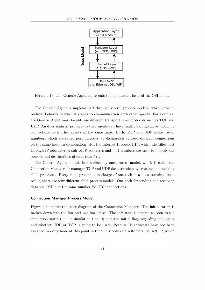
4.5. OPNET MODELER INTEGRATION
Figure 4.13: The Generic Agent represents the application layer of the OSI model.
The Generic Agent is implemented through several process models, which provide
realistic behaviours when it comes to communication with other agents. For example,
the Generic Agent must be able use different transport layer protocols such as TCP and
UDP. Another realistic property is that agents can have multiple outgoing or incoming
connections with other agents at the same time. Both, TCP and UDP make use of
numbers, which are called port numbers, to distinguish between different connections
on the same host. In combination with the Internet Protocol (IP), which identifies host
through IP addresses, a pair of IP addresses and port numbers are used to identify the
sources and destinations of data transfers.
The Generic Agent module is described by one process model, which is called the
Connection Manager. It manages TCP and UDP data transfers by creating and invoking
child processes. Every child process is in charge of one task in a data transfer. As a
result, there are four different child process models. One each for sending and receiving
data via TCP and the same number for UDP connections.
Connection Manager Process Model
Figure 4.14 shows the state diagram of the Connection Manager. The initialisation is
broken down into the init and late init states. The init state is entered as soon as the
simulation starts (i.e. at simulation time 0) and sets initial flags regarding debugging
and whether UDP or TCP is going to be used. Because IP addresses have not been
assigned to every node at this point in time, it schedules a self-interrupt, self int, which
87
4.5. OPNET MODELER INTEGRATION
takes it to the late init state. In this second initialisation state, which is scheduled for
just 1µs into the simulation, all nodes have been assigned an IP address. Every node
adds its own node ID and IP address to an address map, which is global for the whole
network model. This feature provides an easy way to translate between node IDs and
IP addresses. This is required because the interactions exchanged with JADE contain
node IDs but only IP addresses are used to send data via TCP and UDP. Instead of an
agent-node mapping an agent-ip mapping approach could have been used but this would
be significantly more cumbersome to set up and maintain. This is especially the case if
the network nodes are set to OPNET’s auto address assignment feature, which might
change the assigned IP addresses when the network model is slightly modified.
After the late init state, the process moves directly to the idle state. This sate manages
and invokes child processes that take care of sending and receiving data. To this end,
it maintains a list that maps connection IDs to child processes. A unique connection
ID identifies a connection between a sending and receiving child process. Thus, if data
is received (i.e. default transition), the Connection Manager uses the connection ID of
the data to look up which child process to invoke. The invoked process deals with the
incoming data. Upon its return, the Connection Manager removes the child process from
the table if it finished the data transfer.
Child processes that either send or receive data are created under two circumstances.
First, a process to send data is created in state send init, which is reached when the
Connection Manager is interrupted by the interaction received interrupt. This state
creates and invokes a new child process that sends data via TCP or UDP. The child
process initialises a data transfer and returns with the newly created connection ID,
which is used to add an entry to the process table. The send init state then transitions
back to the idle state.
Similarly, the receiving child processes are created, invoked, and added to the process
map when a connection request interrupt is received. This interrupt originates from
the sending child processes when they initialise a connection. The Connection Manager
process exists until it is destroyed at the end of the overall simulation.
Process Model TCP Send
The process models that send and receive data are implemented according to the connec-
tion flow of their underlying transport protocols such as TCP and UDP. The behaviour
88
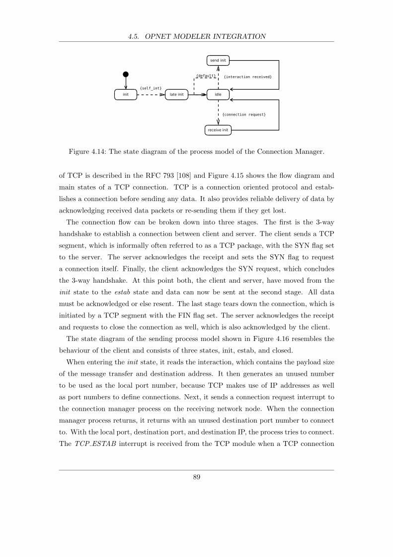
4.5. OPNET MODELER INTEGRATION
Figure 4.14: The state diagram of the process model of the Connection Manager.
of TCP is described in the RFC 793 [108] and Figure 4.15 shows the flow diagram and
main states of a TCP connection. TCP is a connection oriented protocol and estab-
lishes a connection before sending any data. It also provides reliable delivery of data by
acknowledging received data packets or re-sending them if they get lost.
The connection flow can be broken down into three stages. The first is the 3-way
handshake to establish a connection between client and server. The client sends a TCP
segment, which is informally often referred to as a TCP package, with the SYN flag set
to the server. The server acknowledges the receipt and sets the SYN flag to request
a connection itself. Finally, the client acknowledges the SYN request, which concludes
the 3-way handshake. At this point both, the client and server, have moved from the
init state to the estab state and data can now be sent at the second stage. All data
must be acknowledged or else resent. The last stage tears down the connection, which is
initiated by a TCP segment with the FIN flag set. The server acknowledges the receipt
and requests to close the connection as well, which is also acknowledged by the client.
The state diagram of the sending process model shown in Figure 4.16 resembles the
behaviour of the client and consists of three states, init, estab, and closed.
When entering the init state, it reads the interaction, which contains the payload size
of the message transfer and destination address. It then generates an unused number
to be used as the local port number, because TCP makes use of IP addresses as well
as port numbers to define connections. Next, it sends a connection request interrupt to
the connection manager process on the receiving network node. When the connection
manager process returns, it returns with an unused destination port number to connect
to. With the local port, destination port, and destination IP, the process tries to connect.
The TCP ESTAB interrupt is received from the TCP module when a TCP connection
89
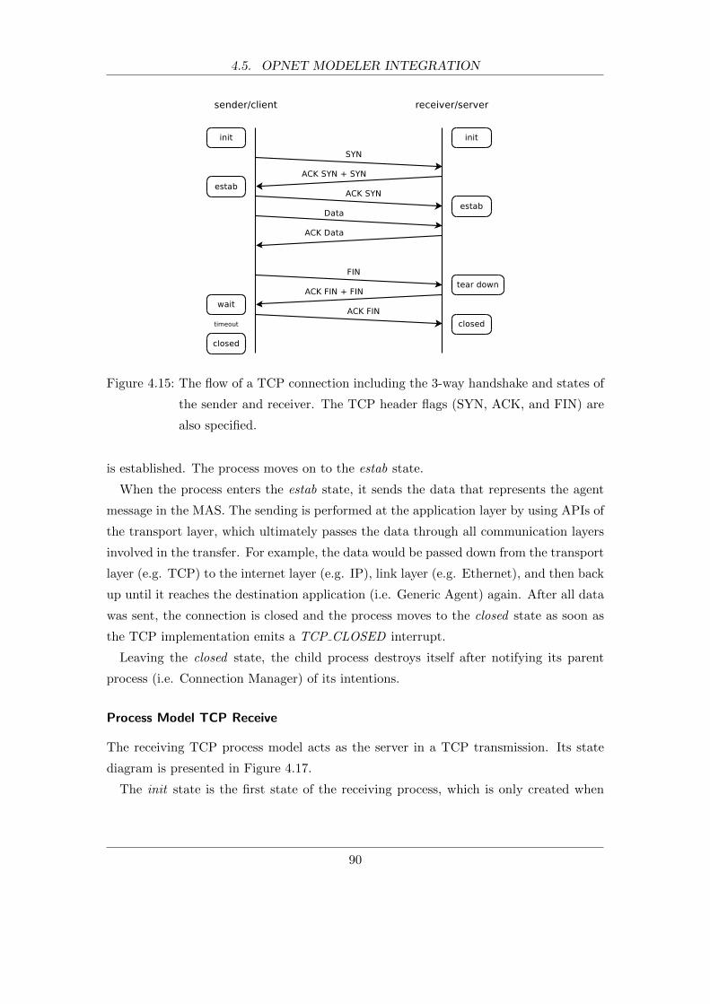
4.5. OPNET MODELER INTEGRATION
Figure 4.15: The flow of a TCP connection including the 3-way handshake and states of
the sender and receiver. The TCP header flags (SYN, ACK, and FIN) are
also specified.
is established. The process moves on to the estab state.
When the process enters the estab state, it sends the data that represents the agent
message in the MAS. The sending is performed at the application layer by using APIs of
the transport layer, which ultimately passes the data through all communication layers
involved in the transfer. For example, the data would be passed down from the transport
layer (e.g. TCP) to the internet layer (e.g. IP), link layer (e.g. Ethernet), and then back
up until it reaches the destination application (i.e. Generic Agent) again. After all data
was sent, the connection is closed and the process moves to the closed state as soon as
the TCP implementation emits a TCP CLOSED interrupt.
Leaving the closed state, the child process destroys itself after notifying its parent
process (i.e. Connection Manager) of its intentions.
Process Model TCP Receive
The receiving TCP process model acts as the server in a TCP transmission. Its state
diagram is presented in Figure 4.17.
The init state is the first state of the receiving process, which is only created when
90

4.5. OPNET MODELER INTEGRATION
Figure 4.16: The state diagram of the process model that sends data via TCP.
the Connection Manager receives a connection request interrupt from a sending process.
Entering this state, it generates an unused port number, which is returned to the sending
process, and opens a passive TCP connection. The connection listens on the just created
port number for incoming TCP connections.
Once a TCP connection is established though the 3-way handshake (TCP ESTAB),
it reads the incoming data stream whenever it receives a TCP SEG FWD interrupt,
which notifies the application of a newly arrived TCP segment. This lasts until the
current TCP connection is terminated and the process receives a TCP FIN RECEIVED
interrupt.
Entering the tear down state, the process closes the TCP connection on its end. As
soon as it receives a TCP CLOSED interrupt from the TCP module, it destroys itself
after informing the parent process of its state.
Figure 4.17: The state diagram of the process model that receives data via TCP.
Process Model UDP Send
Compared to TCP, UDP is a simpler protocol that does not provide reliable communi-
cation. It is a message-based connectionless protocol, which is defined in RFC 768 [109].
As a result, there is no protocol overhead for an initial handshake to establish a con-
91
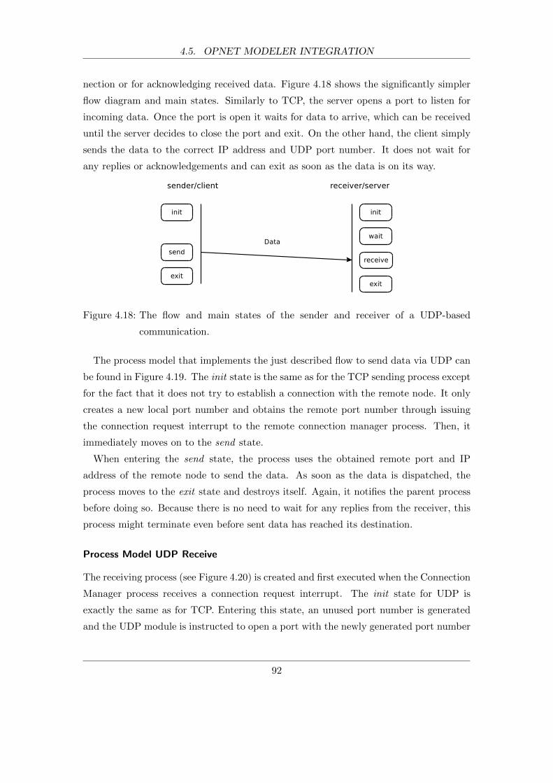
4.5. OPNET MODELER INTEGRATION
nection or for acknowledging received data. Figure 4.18 shows the significantly simpler
flow diagram and main states. Similarly to TCP, the server opens a port to listen for
incoming data. Once the port is open it waits for data to arrive, which can be received
until the server decides to close the port and exit. On the other hand, the client simply
sends the data to the correct IP address and UDP port number. It does not wait for
any replies or acknowledgements and can exit as soon as the data is on its way.
Figure 4.18: The flow and main states of the sender and receiver of a UDP-based
communication.
The process model that implements the just described flow to send data via UDP can
be found in Figure 4.19. The init state is the same as for the TCP sending process except
for the fact that it does not try to establish a connection with the remote node. It only
creates a new local port number and obtains the remote port number through issuing
the connection request interrupt to the remote connection manager process. Then, it
immediately moves on to the send state.
When entering the send state, the process uses the obtained remote port and IP
address of the remote node to send the data. As soon as the data is dispatched, the
process moves to the exit state and destroys itself. Again, it notifies the parent process
before doing so. Because there is no need to wait for any replies from the receiver, this
process might terminate even before sent data has reached its destination.
Process Model UDP Receive
The receiving process (see Figure 4.20) is created and first executed when the Connection
Manager process receives a connection request interrupt. The init state for UDP is
exactly the same as for TCP. Entering this state, an unused port number is generated
and the UDP module is instructed to open a port with the newly generated port number
92

4.6. FEDERATION EXECUTION DETAILS (FED) FILE
Figure 4.19: The state diagram of the process model that sends data via UDP.
and listen for incoming data. The process waits in the wait state until it receives a
UDP RECEIVE interrupt from the UDP module. This interrupt is emitted if data has
arrived and the process can read it off the data stream. After reading the received data,
the process moves on to the final state where it destroys itself.
Figure 4.20: The state diagram of the process model that receives data via UDP.
Process Models for Other Transport Layer Protocols
In its current form, the Generic Agent module supports the most widely used transport
layer protocols TCP and UDP but support for other transport layer protocols such as
the Stream Control Transmission Protocol (RFC 3286 [110]) can be added in a similar
fashion.
4.6 Federation Execution Details (FED) File
The Federation Execution Details (FED) file describes the Federation Object Model
(FOM) of the federation, which defines the data objects that are exchanged between
the federates. The FED file of the MAC-Sim co-simulation platform is shared between
93

4.6. FEDERATION EXECUTION DETAILS (FED) FILE
Figure 4.21: The Federation Object Model of the MAS-Sim platform.
the extended JADE and OPNET Modeler and describes the FOM in Figure 4.21. The
relevant lines of the FED file is shown below:
Listing 4.3: Federation Execution Details file.
1 (FED
2 ( Federat ion MAC−Sim )
3 ( FEDversion v1 . 3 )
4 ( i n t e r a c t i o n s
5 ( c l a s s In te rac t i onRoot r e l i a b l e timestamp
6 ( c l a s s AgentMessage r e l i a b l e timestamp
7 ( parameter source−address )
8 ( parameter de s t i na t i on−address )
9 ( parameter payload−s i z e )
10 ( parameter message−id )
11 ( parameter timestamp )
12 )
13 )
14 )
15 )
The file mainly contains the description of objects and their attributes, parameters,
transport types, and relationships. Brackets are used to define their scope and hierarchy.
The root object is by definition called FED and is on the very top of the hierarchy. Lines 2
and 3 give the federation a name and define the version of the FED file format. Starting
at line 4, the interactions are defined. All interaction classes must be inherited from
the InteractionRoot class. The interactions that are sent between JADE and OPNET
are defined on lines 6 to 11. It has two attributes set and 5 parameters defined. The
94
4.7. PERFORMANCE CONSIDERATIONS
attributes turn on reliable data transport and tells the RTI that all interactions of this
type are timestamped. Overall, the FED file describes the FOM with all its data fields.
4.7 Performance Considerations
It is difficult to gauge the absolute execution times of simulation platforms. Absolute
times can only be measured for specific simulation models that are simulated on specific
simulation hardware. However, it is possible to look at computational complexities and
their impact on how well simulation tools scale. While it is known that the individual
software tools, JADE and OPNET Modeler, can scale easily to a significant number
of agents and network nodes, it needs to be shown that this is also true for MAC-Sim.
Thus, the focus here is on defining the computational complexities that have been added
in the course of the platform development. The complexities are expressed in the Big-O
notation.
The Big-O notation expresses the runtime of an algorithm with respect to the input
size n. In our context the input size is the number of agents and network nodes that are
simulated. For example, if the runtime of an algorithm grows linearly with the number of
agents/nodes, it is said that the complexity is O(n). If the runtime is constant regardless
of the input size, the complexity is O(1). The most typical types are: constant O(1),
logarithmic O(log(n)), linear O(n), n-log-n O(nlog(n)), and quadratic O(n2).
It is important to understand that the Big-O notation does not describe the runtime in
absolute values. For example, two algorithms with linear behaviour are both classified as
O(n) even though one might perform better than the other in terms of absolute runtime.
4.7.1 Computational Complexities
Table 4.2 lists the computational complexities of the operations on data structures that
can grow with the number of simulated agents and network nodes. Both, the FedAgent
and the RTIAgent use sorted linked lists to maintain their behaviour or event lists.
While the sizes of the behaviour lists are usually very small but may be influenced by
the number of agents in the MAS, the size of the event list of the RTIAgent is always the
number of registered FedAgents plus any incoming message events. As can be seen in
the table, the worst complexity is O(n), which happens when a new list element has to
be inserted into the existing sorted list. In fact, O(n) represents the worst-case for this
operation, which holds true if every insertion is made at the very end of the sorted list.
95

4.8. SUMMARY
Table 4.2: Computational complexities of added simulation components. Number of
agents and network nodes is denoted as n.
Component Data Structure Operation Complexity
FedAgent sorted behaviour list insert/read O(n)/O(1)
RTIAgent
sorted event list insert/read O(n)/O(1)
map (agent ID, node ID) add/get O(1)/O(1)
map (message ID, agent messages) add/get O(1)/O(1)
Connection Managermap (node ID, IP addresses) add/get O(1)/O(1)
map (connection ID, child process) add/get O(1)/O(1)
On the other hand, there is a constant runtime (O(1)) for reading the next behaviour
or event from the sorted lists because they are always at the beginning of the lists and
no search is required.
Another data structure that is used is the map. A map can be thought of a table
with two columns for which the entries in the second column can be found through
their associated elements in the first column. Both, adding and finding map elements,
can be performed with constant complexity (O(1)) provided that the maximum size
of the map is known or well guessed. The RTIAgent reads the agent-node mapping
file into a map and stores intercepted agent messages in a map for later delivery. The
Connection Manager process also utilises maps to associate node IDs with IP addresses
and connection IDs with their associated child processes.
Considering all computational complexities of the added simulation components, the
added runtime increases linearly with the number of simulated agents and network nodes.
This suggests that the developed components scale well and do not introduce a significant
performance overhead. Specific data on the performance of the simulation platform is
given later for the case study as part of the results in section 5.7.
4.8 Summary
This chapter presented an implementation of a co-simulation platform that was based on
the design and architecture suggested in the previous chapter. It was named MAC-Sim
(Multi-Agent and Communication Simulator) and it federates the Java Agent DEvelop-
ment Framework (JADE) with the OPNET Modeler.
96
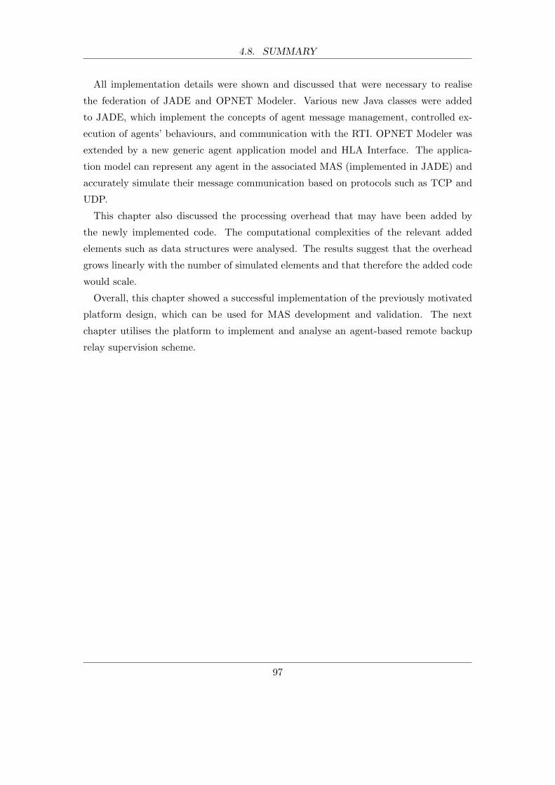
4.8. SUMMARY
All implementation details were shown and discussed that were necessary to realise
the federation of JADE and OPNET Modeler. Various new Java classes were added
to JADE, which implement the concepts of agent message management, controlled ex-
ecution of agents’ behaviours, and communication with the RTI. OPNET Modeler was
extended by a new generic agent application model and HLA Interface. The applica-
tion model can represent any agent in the associated MAS (implemented in JADE) and
accurately simulate their message communication based on protocols such as TCP and
UDP.
This chapter also discussed the processing overhead that may have been added by
the newly implemented code. The computational complexities of the relevant added
elements such as data structures were analysed. The results suggest that the overhead
grows linearly with the number of simulated elements and that therefore the added code
would scale.
Overall, this chapter showed a successful implementation of the previously motivated
platform design, which can be used for MAS development and validation. The next
chapter utilises the platform to implement and analyse an agent-based remote backup
relay supervision scheme.
97
5 Agent-Based Remote Backup Relay
Supervision Case Study
5.1 Introduction
An agent-based remote backup relay supervision scheme has been built, simulated, and
assessed with the help of the MAC-Sim platform. A relay supervision scheme is a delay-
sensitive and time-critical application and therefore a representative example of the
type of application for which the platform is useful. The purpose of the implemented
supervision scheme is to help prevent unnecessary transmission line tripping due to
hidden failures of relays. The scheme has been applied to the IEEE 39-bus system (see
Figure 5.1) and assessed through simulation for different communication technologies,
communication network topologies, and multi-agent system behaviours. The obtained
simulation results have been used to quantify the impact of communication delays on
the supervision scheme and to suggest the most suitable technologies for deployment.
The implemented MAS has also been deployed on a small scale as a prove of concept.
5.2 Transmission System Protection
Some terminologies and aspects of transmission system protection need to be explained
before the details of the supervision scheme can be introduced.
The transmission system is protected by detecting faults as early as possible and dis-
connecting malfunctioning equipment in order to prevent damages and keep up normal
operation. The most important equipment in this context are relays and circuit break-
ers. The relays try to detect faults on transmission lines by monitoring voltages and
electric currents. If a fault is detected, they operate the circuit breakers to isolate it by
disconnecting transmission lines, which is also know as breaking lines or tripping lines.
Typical relays used on transmission lines are various types of overcurrent and distance
98
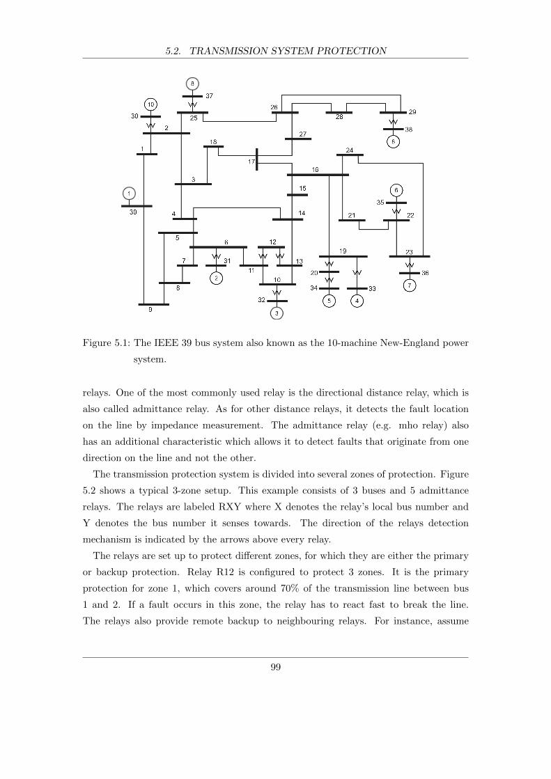
5.2. TRANSMISSION SYSTEM PROTECTION
Figure 5.1: The IEEE 39 bus system also known as the 10-machine New-England power
system.
relays. One of the most commonly used relay is the directional distance relay, which is
also called admittance relay. As for other distance relays, it detects the fault location
on the line by impedance measurement. The admittance relay (e.g. mho relay) also
has an additional characteristic which allows it to detect faults that originate from one
direction on the line and not the other.
The transmission protection system is divided into several zones of protection. Figure
5.2 shows a typical 3-zone setup. This example consists of 3 buses and 5 admittance
relays. The relays are labeled RXY where X denotes the relay’s local bus number and
Y denotes the bus number it senses towards. The direction of the relays detection
mechanism is indicated by the arrows above every relay.
The relays are set up to protect different zones, for which they are either the primary
or backup protection. Relay R12 is configured to protect 3 zones. It is the primary
protection for zone 1, which covers around 70% of the transmission line between bus
1 and 2. If a fault occurs in this zone, the relay has to react fast to break the line.
The relays also provide remote backup to neighbouring relays. For instance, assume
99
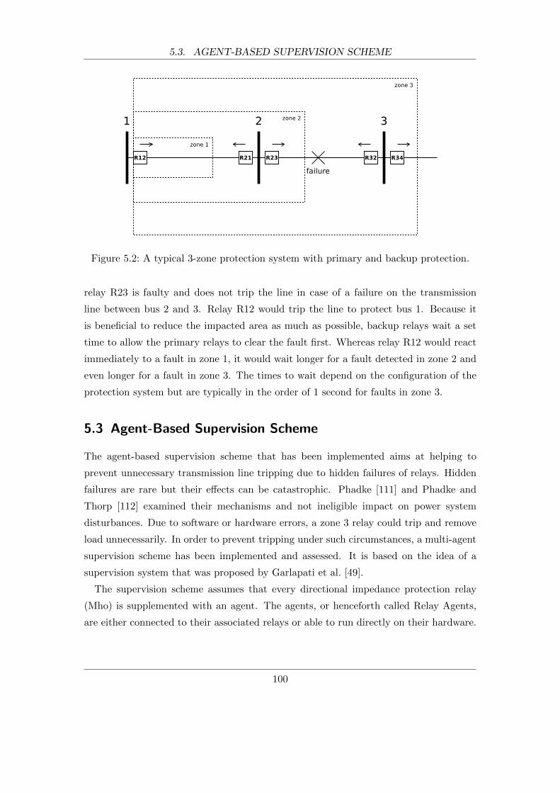
5.3. AGENT-BASED SUPERVISION SCHEME
Figure 5.2: A typical 3-zone protection system with primary and backup protection.
relay R23 is faulty and does not trip the line in case of a failure on the transmission
line between bus 2 and 3. Relay R12 would trip the line to protect bus 1. Because it
is beneficial to reduce the impacted area as much as possible, backup relays wait a set
time to allow the primary relays to clear the fault first. Whereas relay R12 would react
immediately to a fault in zone 1, it would wait longer for a fault detected in zone 2 and
even longer for a fault in zone 3. The times to wait depend on the configuration of the
protection system but are typically in the order of 1 second for faults in zone 3.
5.3 Agent-Based Supervision Scheme
The agent-based supervision scheme that has been implemented aims at helping to
prevent unnecessary transmission line tripping due to hidden failures of relays. Hidden
failures are rare but their effects can be catastrophic. Phadke [111] and Phadke and
Thorp [112] examined their mechanisms and not ineligible impact on power system
disturbances. Due to software or hardware errors, a zone 3 relay could trip and remove
load unnecessarily. In order to prevent tripping under such circumstances, a multi-agent
supervision scheme has been implemented and assessed. It is based on the idea of a
supervision system that was proposed by Garlapati et al. [49].
The supervision scheme assumes that every directional impedance protection relay
(Mho) is supplemented with an agent. The agents, or henceforth called Relay Agents,
are either connected to their associated relays or able to run directly on their hardware.
100
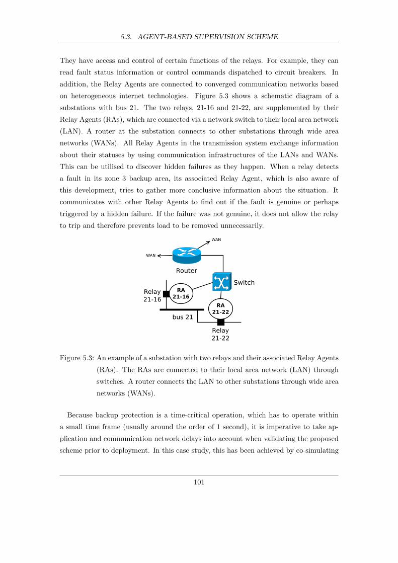
5.3. AGENT-BASED SUPERVISION SCHEME
They have access and control of certain functions of the relays. For example, they can
read fault status information or control commands dispatched to circuit breakers. In
addition, the Relay Agents are connected to converged communication networks based
on heterogeneous internet technologies. Figure 5.3 shows a schematic diagram of a
substations with bus 21. The two relays, 21-16 and 21-22, are supplemented by their
Relay Agents (RAs), which are connected via a network switch to their local area network
(LAN). A router at the substation connects to other substations through wide area
networks (WANs). All Relay Agents in the transmission system exchange information
about their statuses by using communication infrastructures of the LANs and WANs.
This can be utilised to discover hidden failures as they happen. When a relay detects
a fault in its zone 3 backup area, its associated Relay Agent, which is also aware of
this development, tries to gather more conclusive information about the situation. It
communicates with other Relay Agents to find out if the fault is genuine or perhaps
triggered by a hidden failure. If the failure was not genuine, it does not allow the relay
to trip and therefore prevents load to be removed unnecessarily.
Figure 5.3: An example of a substation with two relays and their associated Relay Agents
(RAs). The RAs are connected to their local area network (LAN) through
switches. A router connects the LAN to other substations through wide area
networks (WANs).
Because backup protection is a time-critical operation, which has to operate within
a small time frame (usually around the order of 1 second), it is imperative to take ap-
plication and communication network delays into account when validating the proposed
scheme prior to deployment. In this case study, this has been achieved by co-simulating
101
5.4. MULTI-AGENT SYSTEM IMPLEMENTATION
the supervision scheme and its underlying communication infrastructure with MAC-Sim.
The supervision scheme does not utilise information of the power system behaviour and
therefore power network simulation tools were not needed to find out if the proposed
scheme can operate under the afore mentioned time-critical conditions. As a positive
side effect, the exclusion of power network simulation helps reduce the time to execute
the simulations.
The case study includes the simulation and comparison of several multi-agent sys-
tems and communication network scenarios. For example, different multi-agent com-
munication approaches such as client-server and peer-to-peer strategies were simulated.
Similarly, various network scenarios were studied, which for instance included different
transport protocols, competing traffic, and quality of service strategies. For all scenarios
and multi-agent system, the performance of the protection scheme was evaluated. The
performance is measured as the time the agent-based scheme took to establish if an
introduced fault was genuine or not. The stochastic nature of these simulated domains
was taken into account by running the same simulation models and scenarios a great
number of times with different seed values for the random number generators.
The next sections describe the simulation models and how the were simulated in detail
before discussing the obtained results.
5.4 Multi-Agent System Implementation
The supervision scheme was implemented as a multi-agent system (MAS) with the use
of the extended JADE framework. Two different systems were compared, which offer
the same functionality but their communication approaches differ from each other. One
system is based on a client-server (c/s) approach whereas the other on a peer-to-peer
(p2p) approach as shown in Figure 5.4.
5.4.1 Client-Server Approach
The client-server approach makes use of a domain master agent (DMA) to request in-
formation about other relays in the system. The DMA knows the topology of the bus
system and relays for its domain. There is only one DMA for the IEEE 39 bus system
but the supervision scheme can scale to larger system, which could be broken down into
several areas or domains.
102

5.4. MULTI-AGENT SYSTEM IMPLEMENTATION
Figure 5.4: Client-Server (a) and peer-to-peer (b) strategy of the Relay Agents (RA).
The Domain Master Agent (DMA) knows the topology of the bus system
and relays for its domain. The numbers indicate the sequence of message
exchanges.
When a zone 3 Relay Agent detects a fault, it immediately requests help from the
Domain Master Agent (DMA) (step 1). The DMA has the necessary information of the
power system topology to know which of the other Relay Agents is supposed to detect
the same fault. It sends a request for information to all potential Relay Agents in parallel
and waits for all their replies (step 2). Upon receipt of their replies, it evaluates them
and decides whether this is a genuine fault or not. It then forwards its decision to the
initial Relay Agent (step 3). With this information the zone 3 Relay Agent either allows
the protection relay to trip or not after its predefined waiting time.
5.4.2 Peer-to-Peer Approach
The peer-to-peer approach (see Figure 5.4b) differs from the client-server strategy in
that the zone 3 Relay Agent contacts potential Relay Agents directly without going
through the DMA. Because this approach cuts out the DMA, it is expected to perform
better than the client-server approach with respect to communication delays. It is also
more reliable as the DMA presents a single point of failure and at least a second standby
DMA would have to be deployed.
103
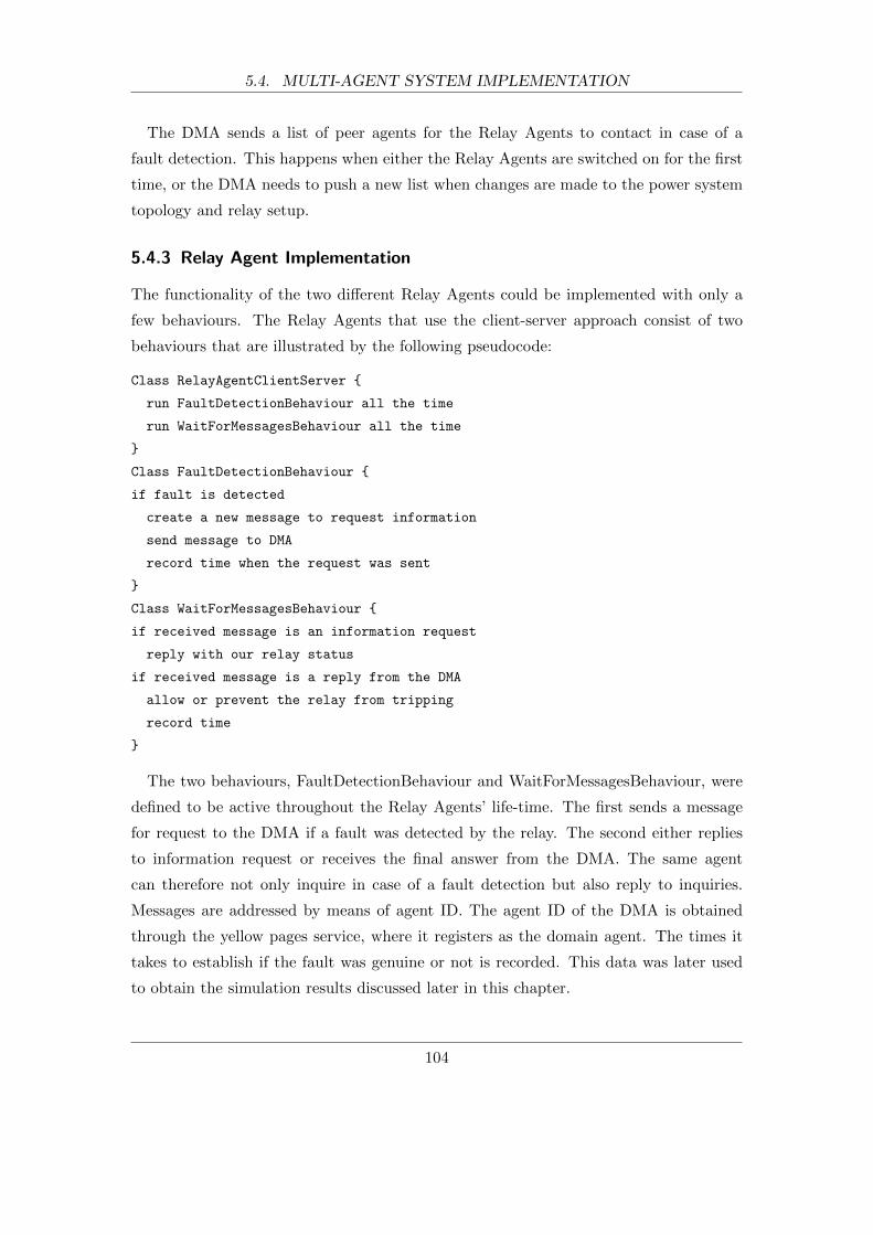
5.4. MULTI-AGENT SYSTEM IMPLEMENTATION
The DMA sends a list of peer agents for the Relay Agents to contact in case of a
fault detection. This happens when either the Relay Agents are switched on for the first
time, or the DMA needs to push a new list when changes are made to the power system
topology and relay setup.
5.4.3 Relay Agent Implementation
The functionality of the two different Relay Agents could be implemented with only a
few behaviours. The Relay Agents that use the client-server approach consist of two
behaviours that are illustrated by the following pseudocode:
Class RelayAgentClientServer {
run FaultDetectionBehaviour all the time
run WaitForMessagesBehaviour all the time
}
Class FaultDetectionBehaviour {
if fault is detected
create a new message to request information
send message to DMA
record time when the request was sent
}
Class WaitForMessagesBehaviour {
if received message is an information request
reply with our relay status
if received message is a reply from the DMA
allow or prevent the relay from tripping
record time
}
The two behaviours, FaultDetectionBehaviour and WaitForMessagesBehaviour, were
defined to be active throughout the Relay Agents’ life-time. The first sends a message
for request to the DMA if a fault was detected by the relay. The second either replies
to information request or receives the final answer from the DMA. The same agent
can therefore not only inquire in case of a fault detection but also reply to inquiries.
Messages are addressed by means of agent ID. The agent ID of the DMA is obtained
through the yellow pages service, where it registers as the domain agent. The times it
takes to establish if the fault was genuine or not is recorded. This data was later used
to obtain the simulation results discussed later in this chapter.
104
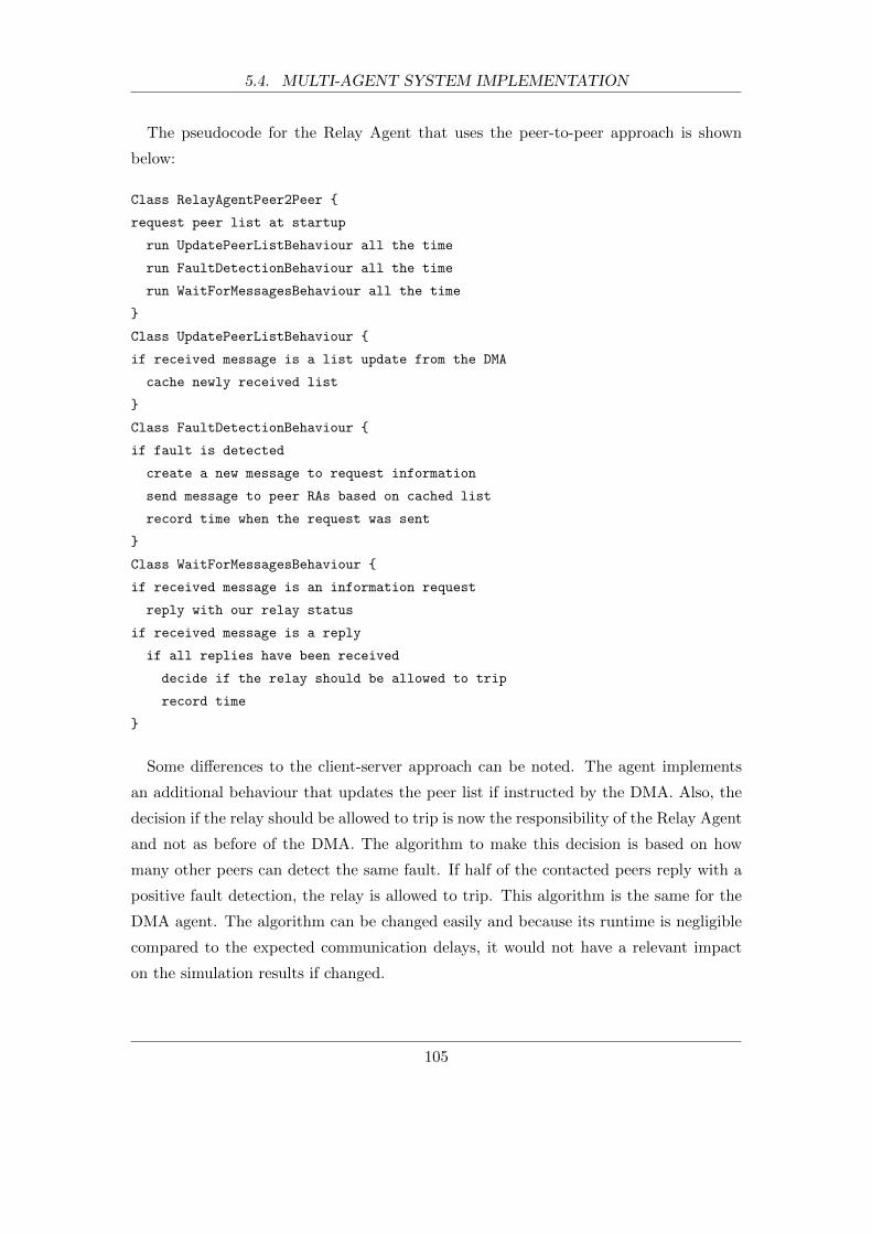
5.4. MULTI-AGENT SYSTEM IMPLEMENTATION
The pseudocode for the Relay Agent that uses the peer-to-peer approach is shown
below:
Class RelayAgentPeer2Peer {
request peer list at startup
run UpdatePeerListBehaviour all the time
run FaultDetectionBehaviour all the time
run WaitForMessagesBehaviour all the time
}
Class UpdatePeerListBehaviour {
if received message is a list update from the DMA
cache newly received list
}
Class FaultDetectionBehaviour {
if fault is detected
create a new message to request information
send message to peer RAs based on cached list
record time when the request was sent
}
Class WaitForMessagesBehaviour {
if received message is an information request
reply with our relay status
if received message is a reply
if all replies have been received
decide if the relay should be allowed to trip
record time
}
Some differences to the client-server approach can be noted. The agent implements
an additional behaviour that updates the peer list if instructed by the DMA. Also, the
decision if the relay should be allowed to trip is now the responsibility of the Relay Agent
and not as before of the DMA. The algorithm to make this decision is based on how
many other peers can detect the same fault. If half of the contacted peers reply with a
positive fault detection, the relay is allowed to trip. This algorithm is the same for the
DMA agent. The algorithm can be changed easily and because its runtime is negligible
compared to the expected communication delays, it would not have a relevant impact
on the simulation results if changed.
105
5.4. MULTI-AGENT SYSTEM IMPLEMENTATION
All created behaviours were modelled with the assumption that it would take each of
them 1ms to process on the deployed hardware. Once the initial agent development is
completed, the agents can be deployed and the actual processing times can be measured
on the target hardware. The processing times can then be adjusted for the next devel-
opment cycle and subsequent simulations. Note that behaviour processing times can be
given in form of probability distribution functions and do not have to be fixed values.
5.4.4 Domain Master Agent Implementation
The main attribute of the Domain Master Agent (DMA) is that it knows the topology
of the power system and protection relays for its domain. This knowledge enables it
to either query the right peer Relay Agents (client-server approach) or instruct the
individual Relay Agents which peers to query (peer-to-peer approach) in case of an
suspected fault. For the DMA the topology is described in the form of groups of relays
that protect the same transmission lines. A group is formed for every transmission line
in the system. Figure 5.5 shows the numbering scheme for every line from P1 to P34.
For example, the group for line P2 would contain the 2 primary relays for zone 1 and the
backup relays for zone 2 and 3 as listed in Table 5.1. Relays are named in the form of
xx-yy where xx is the number of the local bus and yy the number of the remote bus they
are directed to. With this information about the relationships between the protection
relays in the system, the DMA can select the right peer Relay Agents in case of a fault
detection on any particular transmission line. The grouping information for the whole
bus system can be found in Appendix 7.3.
Two different rules of peer selection were tested. The first one, referred to as normal
selection, selects all Relay Agents that are supposed to detect a fault on the transmission
line in question. The second one selects only the zone 3 Relay Agents from the previous
group, which is called reduced selection. This was tested to show what impact the number
of contacted peer Relay Agents has on the performance of the protection scheme.
The pseudocode for the DMA under the client-server approach is given below:
Class DomainMasterAgentClientServer {
run WaitForMessagesBehaviour all the time
}
Class WaitForMessagesBehaviour {
if received message is an information request
create a new messages to request information
106

5.4. MULTI-AGENT SYSTEM IMPLEMENTATION
P1
P2
P3
P4
P5
P6
P7
P8
P9
P10
P11
P12
P13
P14
P15
P16
P17
P18 P19
P20
P21
P22
P23
P24
P25
P26 P27
P28
P29
P30
P31
P32
P33
P34
Figure 5.5: The numbering scheme for every transmission line of the IEEE bus system.
Table 5.1: Group of relays that protects transmission line P2.
Zone 1 Zone 2 Zone 3
39-01 09-39 08-09
01-39 02-01 25-02
03-02
send messages to peer RAs
if received message is a request reply
if all replies have been received
decide if the relay should be allowed to trip
inform agent that sent the initial request
}
The single behaviour requests information on behalf of an inquiring Relay Agent and
sends the result back to it. The agent ID of the inquiring Relay Agent is used in
combination with the available topology information to compile the list of peer Relay
Agents that are supposed to have detected the same fault in question.
107
5.4. MULTI-AGENT SYSTEM IMPLEMENTATION
For the peer-to-peer approach, an individual peer list is sent down to every Relay
Agent in the system upon request or after changes. This functionality is illustrated
below:
Class DomainMasterAgentPeer2Peer {
run WaitForListRequestBehaviour all the time
}
Class WaitForListRequestBehaviour {
if received message is a request for a peer list update
create a new message with latest peer list
send message to requesting RA
}
5.4.5 Agent Messages
All exchanged agent messages are standardised FIPA-ACL (Agent Communication Lan-
guage) messages. As discussed earlier in section 4.4.1, a FIPA-ACL message is comprised
of the message content, message parameters, and message encoding. The agents in the
supervision scheme send two main types of messages, that are the status request and
status information. Listing 5.1 shows examples of the two types in string encoding as
EBNF (Extended Backus-Naur Form; ISO 14977) notation. Both, the status request
message (from listing line 1 to 8) and the status information message (from line 10
to 17), consist of three message parameters. These are the :sender, :receiver, and
:content. The sender and receiver parameters uniquely describe the sending agent and
receiving agent or set of agents. According to the FIPA specification, agents are iden-
tified by IDs that have the form local-name@platform-name. The agent identification
also includes transport information (:addresses). For example, the request information
message shown is send to agent with the ID 009-039@P009-039, which can be found at
address http://P009-039.sub:1111/acc.
Listing 5.1: Example of two FIPA-ACL messages that are exchanged by the agents.
1 (REQUEST
2 : sender ( agent− i d e n t i f i e r : name 001−039@P001−039
3 : addre s s e s ( sequence http :// P001−039. sub :1111/ acc ) )
4 : r e c e i v e r ( s e t
5 ( agent− i d e n t i f i e r : name 009−039@P009−039
6 : addre s s e s ( sequence http :// P009−039. sub :1111/ acc ) ) )
108

5.5. COMMUNICATION NETWORK MODELS
7 : content ” Status ”
8 )
9
10 (INFORM
11 : sender ( agent− i d e n t i f i e r : name 009−039@P009−039
12 : addre s s e s ( sequence http :// P009−039. sub :1111/ acc ) )
13 : r e c e i v e r ( s e t
14 ( agent− i d e n t i f i e r : name 001−039@P001−039
15 : addre s s e s ( sequence http :// P001−039. sub :1111/ acc ) ) )
16 : content ” Fault detec ted ”
17 )
Apart from the message parameters, an ACL message must contain a performative.
FIPA-ACL defines communication in terms of actions, called the communicative act
(FIPA-ACL Communicative Act Library Specification SC00037). There are several de-
fined performatives of which the protection scheme uses two, which are the request and
inform performatives. They are sent at the beginning of each message (line 1 and line
10). The request performative requests the receiver to perform some action, which for
the Relay Agents means to check the relay status and send it to the enquiring agent.
The inform performative informs the receiver that a given proposition is true, which in
the case of the supervision scheme is the status of the relay.
The size of the agent messages without the actual content is constant. It is constant
because the used naming scheme of addresses and agent IDs have a fixed size. As a
result, the total message size is a maximum of 234 bytes for all messages parameters and
informative except for the content. In order to gauge the impact of different message sizes
on the performance of the supervision scheme, different content sizes were implemented
starting with a minimum of 16 bytes, which added to the fixed 234 bytes makes for a
total of 250 bytes. Note that the total message size discussed here is the payload at
the application level and does not include protocol headers. The network simulator will
correctly add these depending on the used technologies.
5.5 Communication Network Models
Several different communication network models were created to be simulated and as-
sessed for the proposed supervision scheme. The models describe the whole commu-
109
5.5. COMMUNICATION NETWORK MODELS
nication network infrastructure including the hardware devices the agents run on, the
communication equipment, communication links, and communication protocols. One
main network model served as the basis for several other models, which describe differ-
ent scenarios.
5.5.1 Network Infrastructure
Figure 5.6 shows the main network model. The assumed communication network is
spread out across the area of New England and models all communication elements of
the local area network (LAN) of the substations as well as the wide area network (WAN)
communication between them. Every round object denotes a LAN of a substation, which
consists of several Relay Agent nodes, network switches, and one router. The nodes rep-
resent the hardware and software of the Relay Agents as previously discussed in section
4.5.4. They are connected via Fast Ethernet (100BASE-TX; 100 Mbit/s over Cat5 ca-
bles) to network switches (16 port Ethernet switch; ethernet16 switch OPNET model).
The switches are connected via Fast Ethernet to routers (ethernet4 slip8 gtwy OPNET
model), which support 4 internal Ethernet interfaces and 8 external serial interfaces to
connect with routers at other substations. T1 communication links (1.544Mbit/s) are
used for intra-substation communication. The links run along some but not all trans-
mission lines in order to reduce costs. 25% of the bandwidth of every T1 link is reserved
for future demand, which leaves an effective bandwidth of 1.158Mbit/s the routers are
allowed to utilise.
Figure 5.7 shows the IEEE 39-Bus system with the communication network infras-
tructure. Every ellipse denotes a LAN that serves a substation and connects all local
Relay Agents. The intra-substation communication is illustrated by lines between the
LANs.
The main network model consists of 28 LANs with a total of 28 routers, 28 network
switches, and 82 Relay Agent nodes. In addition, 110 Fast Ethernet and 26 T1 links are
part of the model.
5.5.2 Network Scenarios
Several network scenarios were created that aim to represent possible real-life situations.
110

5.5. COMMUNICATION NETWORK MODELS
Figure 5.6: The main communication network model spread out across the area of New
England. Every substation consists of several Relay Agent nodes, network
switches, and routers. They are interconnected via wide area networks that
run along the transmission lines.
111
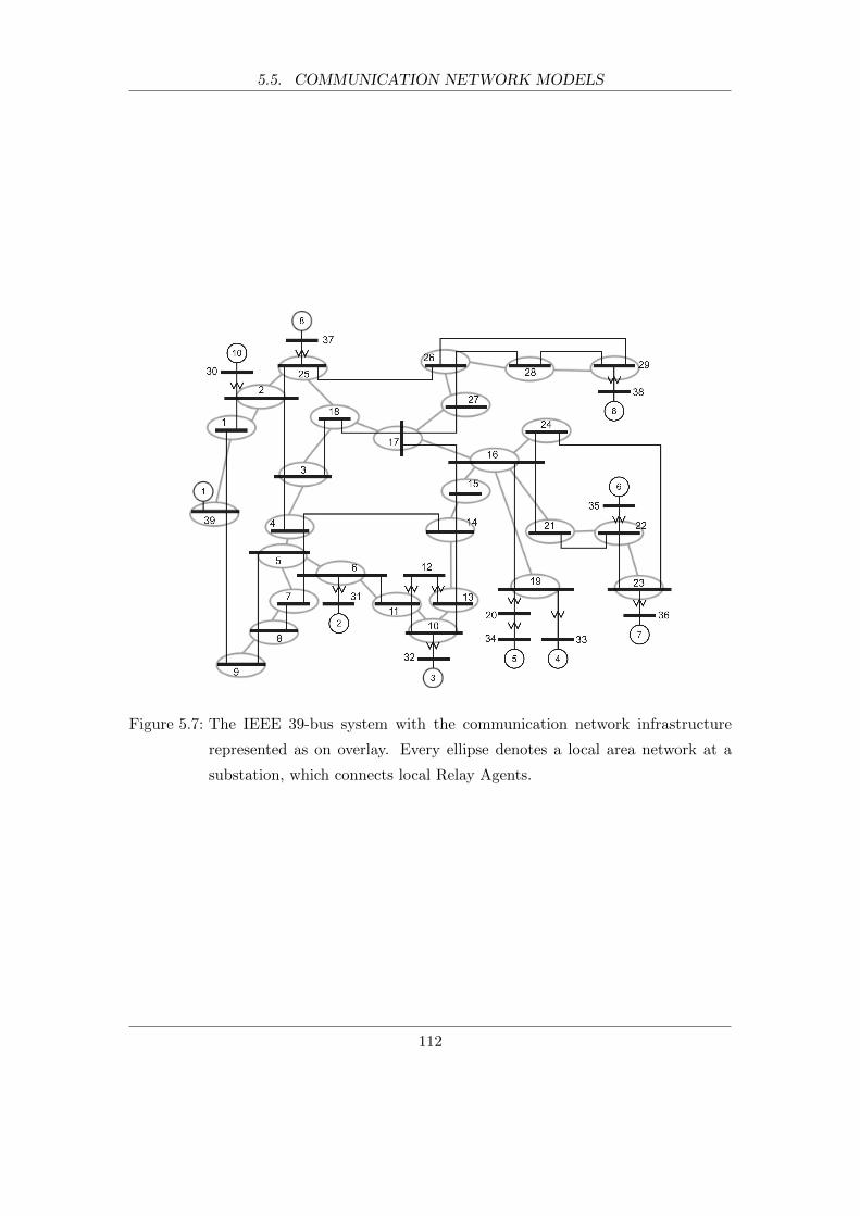
5.5. COMMUNICATION NETWORK MODELS
Figure 5.7: The IEEE 39-bus system with the communication network infrastructure
represented as on overlay. Every ellipse denotes a local area network at a
substation, which connects local Relay Agents.
112
5.5. COMMUNICATION NETWORK MODELS
Dedicated Infrastructure - No Background Traffic (noBT)
It was assumed that the communication infrastructure was dedicated to the Relay Agent
communication and not utilised to transfer any other data traffic. While this scenario
is less likely mainly because of the costs associated with a dedicated infrastructure,
the obtained results for this scenario indicate the best possible performance that can
be achieved without changing the communication infrastructure or technologies. This
scenario was named ”No Background Traffic” (noBT) as there is no other traffic present
than the one created by agent communication.
Competing Background Traffic (BT)
A significantly more realistic scenario is the use of a converged communication network.
In this scenario the network is used to carry data that originates from all kind of different
sources such as office applications, substation monitoring equipment, surveillance videos,
and IP telephony. Therefore, the Relay Agent communication has to compete with
additional traffic, which is called background traffic (BT). An average link utilisation of
around 90% was assumed, which meant that the Relay Agents had to compete with a
1Mbit/s background traffic. For some simulations this link utilisation was also increased
further to investigate its impact.
The background traffic was modeled in OPNET as analytical flows (ip traffic flow
model shipped with OPNET) between all inter-substation links. These flows impact the
performance of the explicitly modeled agent traffic by introducing additional queuing
delays to the network devices.
Quality of Service (QoS)
A Quality of Service (QoS) strategy was implemented to help the agent communication
compete against the background traffic introduced in the previous scenario. In this
context QoS refers to the ability to give different priorities to different types of data
traffic. Because the proposed supervision scheme is time-critical, it is desirable to treat
its traffic more favourable over all other traffic.
The implemented QoS is based on the Differentiated Services (DiffServ) architecture
with class-based weighted fair queueing (CBWFQ) and a low latency queue (LLQ) [113,
114]). In a DiffServ architecture network traffic is classified and treated differently by
network equipment such as routers and switches. Figure 5.8 shows an example of a
113
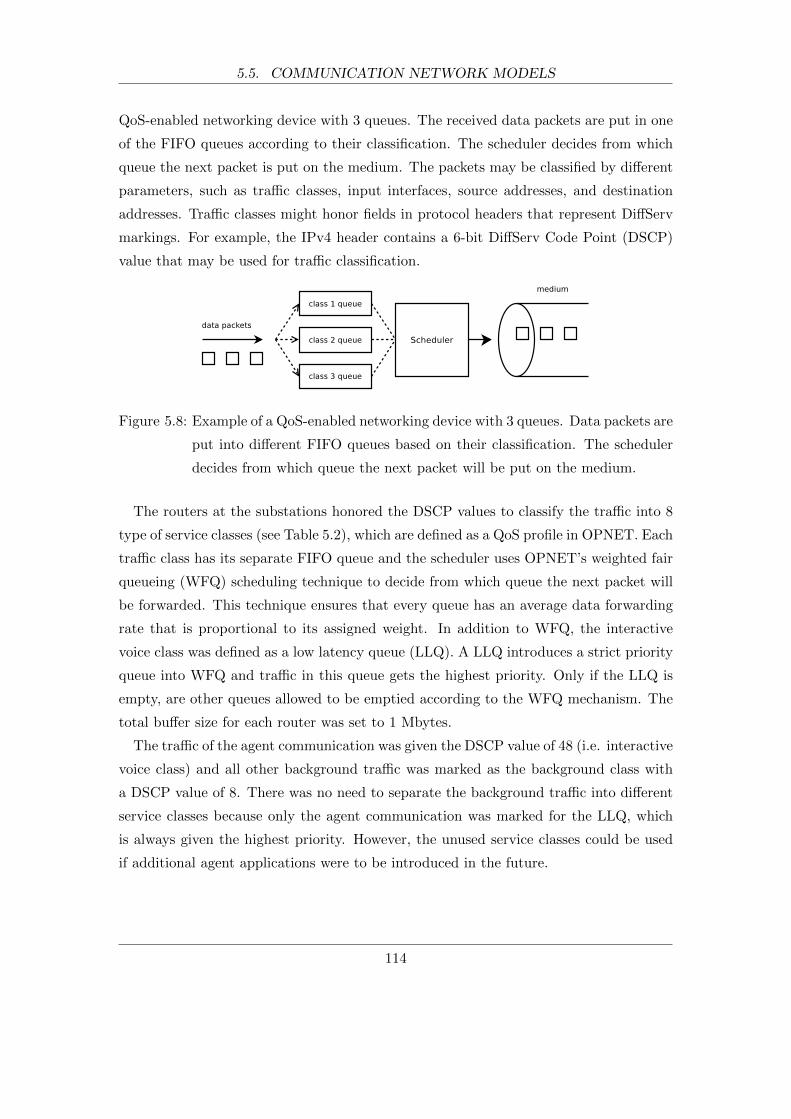
5.5. COMMUNICATION NETWORK MODELS
QoS-enabled networking device with 3 queues. The received data packets are put in one
of the FIFO queues according to their classification. The scheduler decides from which
queue the next packet is put on the medium. The packets may be classified by different
parameters, such as traffic classes, input interfaces, source addresses, and destination
addresses. Traffic classes might honor fields in protocol headers that represent DiffServ
markings. For example, the IPv4 header contains a 6-bit DiffServ Code Point (DSCP)
value that may be used for traffic classification.
Figure 5.8: Example of a QoS-enabled networking device with 3 queues. Data packets are
put into different FIFO queues based on their classification. The scheduler
decides from which queue the next packet will be put on the medium.
The routers at the substations honored the DSCP values to classify the traffic into 8
type of service classes (see Table 5.2), which are defined as a QoS profile in OPNET. Each
traffic class has its separate FIFO queue and the scheduler uses OPNET’s weighted fair
queueing (WFQ) scheduling technique to decide from which queue the next packet will
be forwarded. This technique ensures that every queue has an average data forwarding
rate that is proportional to its assigned weight. In addition to WFQ, the interactive
voice class was defined as a low latency queue (LLQ). A LLQ introduces a strict priority
queue into WFQ and traffic in this queue gets the highest priority. Only if the LLQ is
empty, are other queues allowed to be emptied according to the WFQ mechanism. The
total buffer size for each router was set to 1 Mbytes.
The traffic of the agent communication was given the DSCP value of 48 (i.e. interactive
voice class) and all other background traffic was marked as the background class with
a DSCP value of 8. There was no need to separate the background traffic into different
service classes because only the agent communication was marked for the LLQ, which
is always given the highest priority. However, the unused service classes could be used
if additional agent applications were to be introduced in the future.
114

5.6. SIMULATION SETUP AND EXECUTION
Table 5.2: Implemented traffic classes and their DSCP values and weights.
Class name DSCP value Weight
Best Effort 0 1
Background 8 10
Standard 16 20
Excellent Effort 24 30
Streaming Multimedia 32 40
Interactive Multimedia 40 50
Interactive Voice 48 LLQ
Reserved 56 70
Scenario Variations
While all 3 scenarios (noBT, BT, QoS) were simulated with some common scenario vari-
ations, other variations were only simulated for the most practically relevant scenarios
in order to reduce the overall simulation time to obtain the results. For example, all
3 scenarios were simulated with UDP and TCP as transport protocols, message sizes
of 250 and 350 bytes, peer-to-peer and client/server communication approach. On the
other hand, communication link outages, additional communication links, a wider range
of message sizes, reduced peer selection, and DMA at different substations were mostly
simulated for the QoS scenario and peer-to-peer strategy.
5.6 Simulation Setup and Execution
All simulation components of the MAC-Sim platform were run on the same personal
computer (PC). Its specification is listed in Table 5.3. The platform provides shell
scripts to start the components in the right order. For every simulation run, the RTI
is started first. Then the local JADE platform is executed and implemented agents are
added to it. At the same time the simulation engine of OPNET Modeler is started with
the network model that represents one of the previously described scenarios. Once all
components are started, the co-simulation runs as described in previous chapters and
exits when the simulation end time of the scenario was reached.
Every single scenario was run at least 120 times if not explicitly stated otherwise, to
ensure statistical validity of the results of the stochastic models. Certain elements of a
115

5.6. SIMULATION SETUP AND EXECUTION
Table 5.3: Specifications of the computer that ran the simulations.
Operating System GNU/Linux (Kernel 2.6.32, 64bit)
CPU Intel Core i7-2700K
Clock Speed up to 3.9GHz
Memory 16GB RAM
communication system are stochastic in nature. Their behaviours cannot be described
precisely but characterised by means of probabilities. Typical examples are the occur-
rence of bit-errors related to link quality, access to hardware resources (e.g. CPU and
disks), and various communication protocols that utilise random timers for retransmis-
sions. Such a stochastic system requires stochastic modelling. In order for the simulator
to create variable behaviour, it relies on random number generators to introduce variable
input vectors. It is impossible for a computer to generate genuine random numbers on
its own but a number generator, called pseudo-number generator because the numbers
are not truly random, can be started at specific initial states. These states are specified
for every simulation as values known as seed values. If a scenario is simulated again with
the same seed value as before, it yields exactly the same results. On the other hand, the
same scenario with a different seed value produces different results because the random
numbers used for the stochastic elements were different. As one run with a seed value
might not represent the typical behaviour of the system, numerous runs with different
seeds were carried out to ensure statistical validity. 120 simulation runs were chosen to
ensure that the standard error of the mean (SEM) of all scenarios was below 1ms.
During any of the simulation runs, a hidden failure was simulated for each of the
implemented relay agents. The first relay agent detects a power link failure 10 seconds
(i.e simulation time) after the simulation started to give certain communication network
components the time to initialise, which for example includes IP address assignments and
routing protocols creating their routing tables. The remaining relay agents detect a link
failure one after another with 5 seconds between each detection. The gap of 5 seconds
makes sure that the communication system is not under the influence of the previous
fault detection. Once all relays detected one hidden failure the simulation reaches the
simulation end time and exits. Thus, the simulation end time equals the number of relay
agents (82) times 5 seconds plus 10 seconds (initialisation).
The relay agents record the time it took to identify the hidden fault to a data file.
116
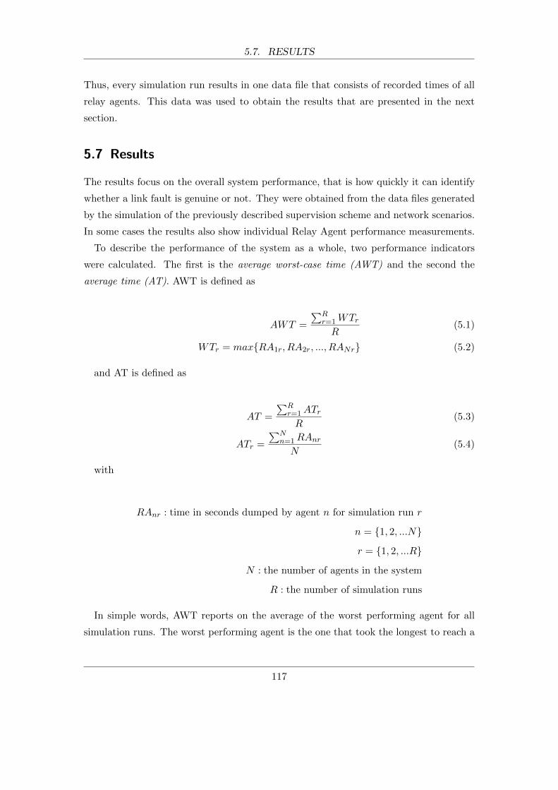
5.7. RESULTS
Thus, every simulation run results in one data file that consists of recorded times of all
relay agents. This data was used to obtain the results that are presented in the next
section.
5.7 Results
The results focus on the overall system performance, that is how quickly it can identify
whether a link fault is genuine or not. They were obtained from the data files generated
by the simulation of the previously described supervision scheme and network scenarios.
In some cases the results also show individual Relay Agent performance measurements.
To describe the performance of the system as a whole, two performance indicators
were calculated. The first is the average worst-case time (AWT) and the second the
average time (AT). AWT is defined as
AWT =
∑Rr=1WTrR
(5.1)
WTr = max{RA1r, RA2r, ..., RANr} (5.2)
and AT is defined as
AT =
∑Rr=1ATrR
(5.3)
ATr =
∑Nn=1RAnr
N(5.4)
with
RAnr : time in seconds dumped by agent n for simulation run r
n = {1, 2, ...N}
r = {1, 2, ...R}
N : the number of agents in the system
R : the number of simulation runs
In simple words, AWT reports on the average of the worst performing agent for all
simulation runs. The worst performing agent is the one that took the longest to reach a
117
5.7. RESULTS
decision on the detected fault. Thus, on average, no Relay Agent in the simulated system
took longer than AWT. On the other hand, AT reports on the average performance of
the agents in the system for all runs. A significant difference between AWT and AT
would indicate that the reported overall system performance (i.e. AWT) is dictated by
only a few poorly performing agents and that improvements might be easily achieved.
5.7.1 Overall MAS Performance
Figure 5.9 summarises the AWTs for the implemented supervision scheme under different
scenarios. The results without background traffic (noBT-c/s and noBT-p2p) indicate
the best possible situation that is achievable only with a dedicated network and that
can only be improved upon by making changes to the network infrastructure. All of
the scenario variations without background traffic considered (e.g. TCP, UDP, 250/350
bytes payload1) would meet the requirement of staying below 1 second. However, in the
presence of other competing background traffic, the choice of communication technologies
and communication strategies becomes crucial. As expected, the use of the UDP protocol
yields better performances compared to the TCP protocol. If TCP is to be used, only
the introduction of QoS can guarantee the required response times for the peer-to-peer
approach or the client-server approach with the smaller payload size of 250 bytes. It can
also be seen that the peer-to-peer approach should be considered in most cases because
it provides the same functionality while improving the performance in most cases by
over 30%.
While Figure 5.9 presents the average worst-case times (AWTs), Figure 5.10 shows the
average times (ATs) for the same scenarios. The substantial different results between
the AWTs and the AT suggest that most agents can perform significantly better than
the AWTs imply.
This is confirmed by Figure 5.11, which shows the average decision times for individual
Relay Agents. The presented scenario is QoS-p2p with TCP and 250 bytes payload. It
can be readily identified which agents perform badly and that times vary greatly from
between 150ms and 550ms. This information can help make educated improvements to
the system, such as adding or upgrading communication links where needed.
Overall, the results suggest that both, TCP and UDP, are suitable if used with the
1The size at the application level, which does not include protocol headers. The headers are correctly
added by the network simulator depending on the used technologies.
118
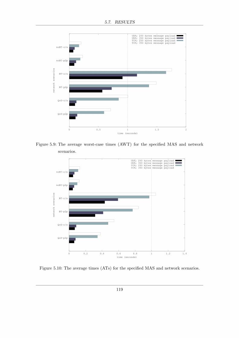
5.7. RESULTS
QoS-p2p
QoS-c/s
BT-p2p
BT-c/s
noBT-p2p
noBT-c/s
0 0.5 1 1.5 2
network scenarios
time (seconds)
UDP; 250 bytes message payloadUDP; 350 bytes message payloadTCP; 250 bytes message payloadTCP; 350 bytes message payload
Figure 5.9: The average worst-case times (AWT) for the specified MAS and network
scenarios.
QoS-p2p
QoS-c/s
BT-p2p
BT-c/s
noBT-p2p
noBT-c/s
0 0.2 0.4 0.6 0.8 1 1.2 1.4
network scenarios
time (seconds)
UDP; 250 bytes message payloadUDP; 350 bytes message payloadTCP; 250 bytes message payloadTCP; 350 bytes message payload
Figure 5.10: The average times (ATs) for the specified MAS and network scenarios.
119

5.7. RESULTS
0.15
0.2
0.25
0.3
0.35
0.4
0.45
0.5
0.55
0.6
001-0
02
001-0
39
002-0
01
002-0
03
002-0
25
003-0
02
003-0
04
003-0
18
004-0
03
004-0
05
004-0
14
005-0
04
005-0
06
005-0
08
006-0
05
006-0
07
006-0
11
007-0
06
007-0
08
008-0
05
008-0
07
008-0
09
009-0
08
009-0
39
010-0
11
010-0
13
011-0
06
011-0
10
011-0
12
012-0
11
012-0
13
013-0
10
013-0
12
013-0
14
014-0
04
014-0
13
014-0
15
015-0
14
015-0
16
016-0
15
016-0
17
016-0
21
016-0
24
017-0
16
017-0
18
017-0
27
018-0
03
018-0
17
019-0
16
020-0
19
021-0
16
021-0
22
022-0
21
022-0
23
023-0
22
023-0
24
024-0
16
024-0
23
025-0
02
025-0
26
026-0
25
026-0
27
026-0
28
026-0
29
027-0
17
027-0
26
028-0
26
028-0
29
029-0
26
029-0
28
030-0
02
031-0
06
032-0
10
033-0
19
034-0
20
035-0
22
036-0
23
037-0
25
038-0
29
039-0
01
039-0
09
tim
e (
se
con
ds)
relay agents
Figure 5.11: The average times for individual Relay Agents (RAs). The results are for
scenario QoS-p2p with TCP and 250 bytes payload. RAs are labelled in
the form of xxx-yyy where xxx is the number of the local bus and yyy the
number of the remote bus the RA is directed to.
120
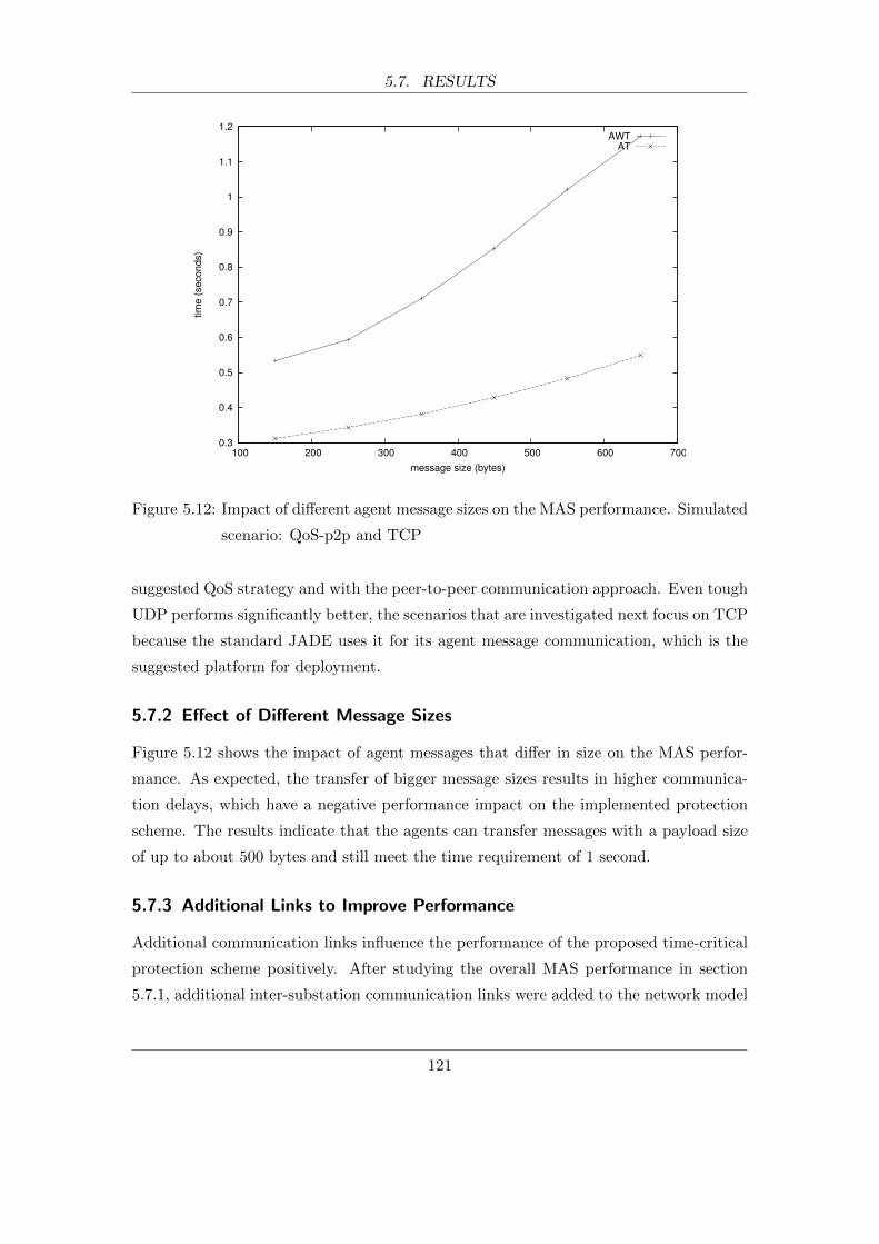
5.7. RESULTS
0.3
0.4
0.5
0.6
0.7
0.8
0.9
1
1.1
1.2
100 200 300 400 500 600 700
tim
e (
seconds)
message size (bytes)
AWTAT
Figure 5.12: Impact of different agent message sizes on the MAS performance. Simulated
scenario: QoS-p2p and TCP
suggested QoS strategy and with the peer-to-peer communication approach. Even tough
UDP performs significantly better, the scenarios that are investigated next focus on TCP
because the standard JADE uses it for its agent message communication, which is the
suggested platform for deployment.
5.7.2 Effect of Different Message Sizes
Figure 5.12 shows the impact of agent messages that differ in size on the MAS perfor-
mance. As expected, the transfer of bigger message sizes results in higher communica-
tion delays, which have a negative performance impact on the implemented protection
scheme. The results indicate that the agents can transfer messages with a payload size
of up to about 500 bytes and still meet the time requirement of 1 second.
5.7.3 Additional Links to Improve Performance
Additional communication links influence the performance of the proposed time-critical
protection scheme positively. After studying the overall MAS performance in section
5.7.1, additional inter-substation communication links were added to the network model
121
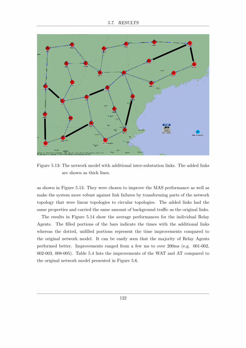
5.7. RESULTS
Figure 5.13: The network model with additional inter-substation links. The added links
are shown as thick lines.
as shown in Figure 5.13. They were chosen to improve the MAS performance as well as
make the system more robust against link failures by transforming parts of the network
topology that were linear topologies to circular topologies. The added links had the
same properties and carried the same amount of background traffic as the original links.
The results in Figure 5.14 show the average performances for the individual Relay
Agents. The filled portions of the bars indicate the times with the additional links
whereas the dotted, unfilled portions represent the time improvements compared to
the original network model. It can be easily seen that the majority of Relay Agents
performed better. Improvements ranged from a few ms to over 200ms (e.g. 001-002,
002-003, 008-005). Table 5.4 lists the improvements of the WAT and AT compared to
the original network model presented in Figure 5.6.
122
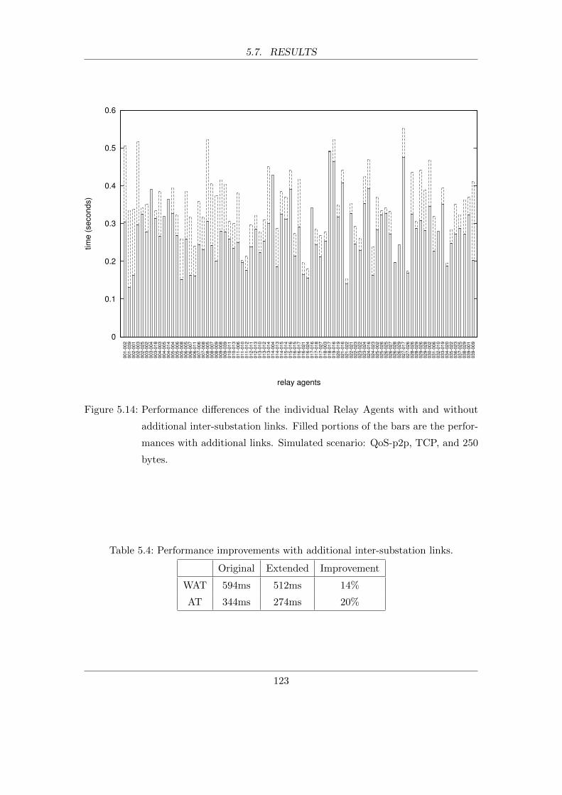
5.7. RESULTS
0
0.1
0.2
0.3
0.4
0.5
0.6
00
1-0
02
00
1-0
39
00
2-0
01
00
2-0
03
00
2-0
25
00
3-0
02
00
3-0
04
00
3-0
18
00
4-0
03
00
4-0
05
00
4-0
14
00
5-0
04
00
5-0
06
00
5-0
08
00
6-0
05
00
6-0
07
00
6-0
11
00
7-0
06
00
7-0
08
00
8-0
05
00
8-0
07
00
8-0
09
00
9-0
08
00
9-0
39
01
0-0
11
01
0-0
13
01
1-0
06
01
1-0
10
01
1-0
12
01
2-0
11
01
2-0
13
01
3-0
10
01
3-0
12
01
3-0
14
01
4-0
04
01
4-0
13
01
4-0
15
01
5-0
14
01
5-0
16
01
6-0
15
01
6-0
17
01
6-0
21
01
6-0
24
01
7-0
16
01
7-0
18
01
7-0
27
01
8-0
03
01
8-0
17
01
9-0
16
02
0-0
19
02
1-0
16
02
1-0
22
02
2-0
21
02
2-0
23
02
3-0
22
02
3-0
24
02
4-0
16
02
4-0
23
02
5-0
02
02
5-0
26
02
6-0
25
02
6-0
27
02
6-0
28
02
6-0
29
02
7-0
17
02
7-0
26
02
8-0
26
02
8-0
29
02
9-0
26
02
9-0
28
03
0-0
02
03
1-0
06
03
2-0
10
03
3-0
19
03
4-0
20
03
5-0
22
03
6-0
23
03
7-0
25
03
8-0
29
03
9-0
01
03
9-0
09
tim
e (
se
co
nd
s)
relay agents
Figure 5.14: Performance differences of the individual Relay Agents with and without
additional inter-substation links. Filled portions of the bars are the perfor-
mances with additional links. Simulated scenario: QoS-p2p, TCP, and 250
bytes.
Table 5.4: Performance improvements with additional inter-substation links.
Original Extended Improvement
WAT 594ms 512ms 14%
AT 344ms 274ms 20%
123
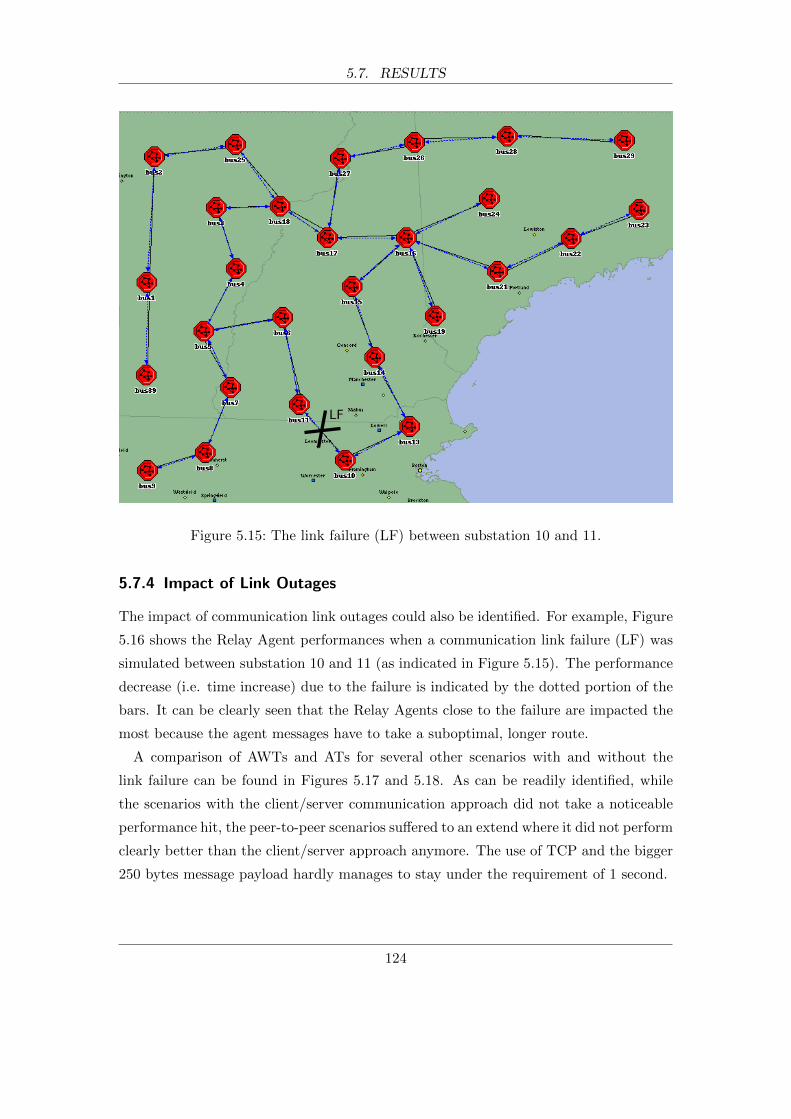
5.7. RESULTS
Figure 5.15: The link failure (LF) between substation 10 and 11.
5.7.4 Impact of Link Outages
The impact of communication link outages could also be identified. For example, Figure
5.16 shows the Relay Agent performances when a communication link failure (LF) was
simulated between substation 10 and 11 (as indicated in Figure 5.15). The performance
decrease (i.e. time increase) due to the failure is indicated by the dotted portion of the
bars. It can be clearly seen that the Relay Agents close to the failure are impacted the
most because the agent messages have to take a suboptimal, longer route.
A comparison of AWTs and ATs for several other scenarios with and without the
link failure can be found in Figures 5.17 and 5.18. As can be readily identified, while
the scenarios with the client/server communication approach did not take a noticeable
performance hit, the peer-to-peer scenarios suffered to an extend where it did not perform
clearly better than the client/server approach anymore. The use of TCP and the bigger
250 bytes message payload hardly manages to stay under the requirement of 1 second.
124

5.7. RESULTS
0
0.1
0.2
0.3
0.4
0.5
0.6
0.7
00
1-0
02
00
1-0
39
00
2-0
01
00
2-0
03
00
2-0
25
00
3-0
02
00
3-0
04
00
3-0
18
00
4-0
03
00
4-0
05
00
4-0
14
00
5-0
04
00
5-0
06
00
5-0
08
00
6-0
05
00
6-0
07
00
6-0
11
00
7-0
06
00
7-0
08
00
8-0
05
00
8-0
07
00
8-0
09
00
9-0
08
00
9-0
39
01
0-0
11
01
0-0
13
01
1-0
06
01
1-0
10
01
1-0
12
01
2-0
11
01
2-0
13
01
3-0
10
01
3-0
12
01
3-0
14
01
4-0
04
01
4-0
13
01
4-0
15
01
5-0
14
01
5-0
16
01
6-0
15
01
6-0
17
01
6-0
21
01
6-0
24
01
7-0
16
01
7-0
18
01
7-0
27
01
8-0
03
01
8-0
17
01
9-0
16
02
0-0
19
02
1-0
16
02
1-0
22
02
2-0
21
02
2-0
23
02
3-0
22
02
3-0
24
02
4-0
16
02
4-0
23
02
5-0
02
02
5-0
26
02
6-0
25
02
6-0
27
02
6-0
28
02
6-0
29
02
7-0
17
02
7-0
26
02
8-0
26
02
8-0
29
02
9-0
26
02
9-0
28
03
0-0
02
03
1-0
06
03
2-0
10
03
3-0
19
03
4-0
20
03
5-0
22
03
6-0
23
03
7-0
25
03
8-0
29
03
9-0
01
03
9-0
09
tim
e (
se
co
nd
s)
relay agents
Figure 5.16: Impact of a link failure (LF) between substation 10 and 11. The dotted
portion of the bars indicate the time increase due to the failure. Simulated
scenario: QoS-p2p, TCP, and 250 bytes.
125

5.7. RESULTS
QoS-LF-p2p
QoS-LF-c/s
QoS-p2p
QoS-c/s
0 0.2 0.4 0.6 0.8 1 1.2 1.4
network scenarios
time (seconds)
UDP; 250 bytes message payloadUDP; 350 bytes message payloadTCP; 250 bytes message payloadTCP; 350 bytes message payload
Figure 5.17: Comparison of AWTs for scenarios with (QoS-LF-c/s, QoS-LF-p2p) and
without the link failure (LF).
QoS-LF-p2p
QoS-LF-c/s
QoS-p2p
0 0.1 0.2 0.3 0.4 0.5 0.6 0.7
network scenarios
time (seconds)
UDP; 250 bytes message payloadUDP; 350 bytes message payloadTCP; 250 bytes message payloadTCP; 350 bytes message payload
Figure 5.18: Comparison of ATs for scenarios with (QoS-LF-c/s, QoS-LF-p2p) and with-
out the link failure (LF).
126
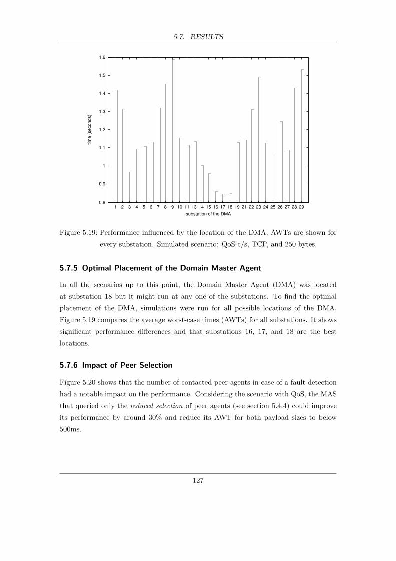
5.7. RESULTS
0.8
0.9
1
1.1
1.2
1.3
1.4
1.5
1.6
1 2 3 4 5 6 7 8 9 10 11 13 14 15 16 17 18 19 21 22 23 24 25 26 27 28 29
tim
e (
se
co
nd
s)
substation of the DMA
Figure 5.19: Performance influenced by the location of the DMA. AWTs are shown for
every substation. Simulated scenario: QoS-c/s, TCP, and 250 bytes.
5.7.5 Optimal Placement of the Domain Master Agent
In all the scenarios up to this point, the Domain Master Agent (DMA) was located
at substation 18 but it might run at any one of the substations. To find the optimal
placement of the DMA, simulations were run for all possible locations of the DMA.
Figure 5.19 compares the average worst-case times (AWTs) for all substations. It shows
significant performance differences and that substations 16, 17, and 18 are the best
locations.
5.7.6 Impact of Peer Selection
Figure 5.20 shows that the number of contacted peer agents in case of a fault detection
had a notable impact on the performance. Considering the scenario with QoS, the MAS
that queried only the reduced selection of peer agents (see section 5.4.4) could improve
its performance by around 30% and reduce its AWT for both payload sizes to below
500ms.
127

5.7. RESULTS
QoS-reduced
QoS-all
BT-reduced
BT-all
noBT-reduced
noBT-all
0 0.5 1 1.5 2
network scenarios
time (seconds)
TCP; 250 bytes message payloadTCP; 350 bytes message payload
QoS-reduced
QoS-all
BT-reduced
BT-all
noBT-reduced
noBT-all
0 0.2 0.4 0.6 0.8 1
network scenarios
time (seconds)
TCP; 250 bytes message payloadTCP; 350 bytes message payload
Figure 5.20: Comparing the AWTs (top) and ATs (bottom) of multi-agents system with
two different peer selection algorithms. One algorithm queried all relevant
peer agents (-all) whereas the other queried a reduced selection (-reduced).
128

5.8. SIMULATION REQUIREMENTS
QoS-p2p
QoS-c/s
BT-p2p
BT-c/s
noBT-p2p
noBT-c/s
0 100 200 300 400 500
network scenarios
execution time (seconds)
UDP; 250 bytes message payloadUDP; 350 bytes message payloadTCP; 250 bytes message payloadTCP; 350 bytes message payload
Figure 5.21: Summarises the simulated scenarios and the times it took to simulate them.
5.8 Simulation Requirements
The next sections report on the time, storage, and memory requirements of the simula-
tions.
5.8.1 Simulation Execution Times
Figure 5.21 summarises the times it took for the scenarios to be simulated with MAC-
Sim. They are the times for one simulation run. It can be easily seen that the type of
communication protocol had a significant influence on the simulation execution times.
The scenarios that used UDP completed in under 1 minute while the same scenarios
that used TCP took significantly longer. The network simulator was the component
responsible for these time differences because neither the RTI nor JADE execute in a
different way when TCP is chosen instead of UDP. Also, this strongly suggests that the
overall execution times are mainly dictated by the performance of the network simulator.
This observation applies to the application simulated in this case study and a system
comprised of agents that are significantly more processor-intensive would probably yield
different results.
129

5.8. SIMULATION REQUIREMENTS
360
380
400
420
440
460
480
0 200 400 600 800 1000 1200 1400 1600 1800 2000
tim
e (
se
co
nd
s)
message size (bytes)
Figure 5.22: The impact of the payload size on the simulation execution time. Simulated
scenario: QoS-p2p with TCP.
The figure also shows small time differences for different message sizes, which seem to
suggest that the execution time also depends on the agent message sizes. This is con-
firmed by Figure 5.22, which plots the different message payloads and their corresponding
simulation times. While the impact is not critical considering the small message sizes
that are viable for the protection scheme, it shows clearly a steep increase at around
1500 bytes. This was expected and is the result of the fact that the Maximum Trans-
mission Unit (MTU) was set to 1500 bytes. The MTU is the size of the largest packet a
network protocol can send. If the payload is bigger than the MTU, the data is divided
into smaller packets. More packets need to be simulated and therefore simulation time
is increased. 1500 is a typical value for the MTU because it is the biggest size allowed
by standard Ethernet.
The execution times presented here were for one simulation run. They need to be
multiplied by the actual number of runs for every scenario to get the total time that was
needed to generate the necessary data. For example, to obtain the results for Figure 5.9,
every one of the 24 scenarios were simulated 120 times, totalling in 2880 runs. Taking the
presented simulation times for the scenarios into account, this resulted in approximately
130

5.8. SIMULATION REQUIREMENTS
Table 5.5: Maximum memory footprint.
JAVA RTI OPNET
Memory 200 MB 30 MB 80 MB
Table 5.6: Installed size of the individual simulation components.
JADE RTI OPNET
Installed size 25 MB 170 MB 2100 MB
166 hours or 7 days of non-stop simulations.
5.8.2 Memory Requirements
The maximum memory footprint of the individual simulation components are sum-
marised in Table 5.5. This included all loaded code, data, and shared libraries. All
components needed a maximum of 310 MB to simulate the previously described scenar-
ios.
The data was obtained with top, which is the ubiquitous tool to display system infor-
mation on GNU/Linux systems. The tool monitored the simulation runs and recorded
the memory requirements of the components every 3 seconds.
5.8.3 Storage Requirements
The storage requirement of the MAC-Sim platform consisted of the individual simulation
components, the simulated models (MAS and network models), and the generated data.
The installed individual simulation components took about 2.3GB as detailed in Table
5.6. This included all code, data, and libraries but not the documentation.
The simulated network models took up around 390 MB and the agent models were
only a couple of megabytes. In total, the required disk space to run the simulations was
almost 2.7GB.
In addition to the required disk space to run the simulations, every simulation run
generated data that was used subsequently to calculate the performance results. For
example, in order to obtain the results presented previously in Figures 5.9 and 5.10,
approximately 1.3GB of data were generated during all necessary simulation runs. Every
simulation run generated a data file which was about 450kB in size. The file included
131
5.9. AGENT MODEL DEPLOYMENT
the times that were recorded by every Relay Agent and debugging information such
as registered agent names, registration status with the RTI, automatically assigned IP
addresses of nodes in OPNET, and when interactions occurred. Considering that the
figures report on 24 total scenarios, each of which were simulated 120 times, that makes
1.296GB (i.e. 450kB * 24 * 120).
A stripped down data file that only included the necessary times recorded by the Relay
Agents would have been just below 100kB and resulted in the generation of 288MB
instead of 1.3GB of data.
5.9 Agent Model Deployment
The implemented Relay Agent code has been ported and deployed on low-cost, low-power
single-board computers. The test deployment confirmed that the same agent code that
was used during simulation can be later used with minor modifications on real devices.
The only changes that were necessary could easily be automated. It also showed how
the actual times to execute the agents’ behaviours could be obtained.
5.9.1 Test Setup
The test deployment is shown in Figure 5.23. It consisted of one 8-port 100Mb/s network
switch and two single-board computers (see Table 5.7 for specifications). Every board
ran one agent and was connected via CAT 6 patch cords to the switch. The IP addresses
of the network cards of the board belonged to the network 192.168.1.0/24.
While this minimal setup did not fully represent the full deployment of the suggested
supervision scheme, which contained 81 agents and other network equipment, it made it
possible to test the functionality of the deployed agent code on a small scale. Apart from
minor modification, which are detailed later, the same developed agent code was used.
The agents were configured to react to a detected fault every 5 seconds after startup
and ran until manually terminated. The two agents worked as intended, that is, they
contacted each other to get their statuses and, as for the simulations, recorded the times
it took to reach a decision.
In addition to this functionality test, the execution times of the agents’ behaviours
(processing delays) were recorded. The recording was done by logging the return value
of the Java function System.currentTimeMilli() at the very beginning and end of every
132
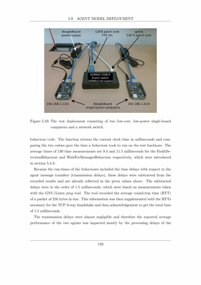
5.9. AGENT MODEL DEPLOYMENT
Figure 5.23: The test deployment consisting of two low-cost, low-power single-board
computers and a network switch.
behaviour code. The function returns the current clock time in milliseconds and com-
paring the two values gave the time a behaviour took to run on the test hardware. The
average times of 130 time measurements are 9.4 and 11.5 milliseconds for the FaultDe-
tectionBehaviour and WaitForMessagesBehaviour respectively, which were introduced
in section 5.4.3.
Because the run-times of the behaviours included the time delays with respect to the
agent message transfers (transmission delays), these delays were subtracted from the
recorded results and are already reflected in the given values above. The subtracted
delays were in the order of 1.5 milliseconds, which were based on measurements taken
with the GNU/Linux ping tool. The tool recorded the average round-trip time (RTT)
of a packet of 250 bytes in size. This information was then supplemented with the RTTs
necessary for the TCP 3-way handshake and data acknowledgement to get the total time
of 1.5 milliseconds.
The transmission delays were almost negligible and therefore the reported average
performance of the two agents was impacted mostly by the processing delays of the
133
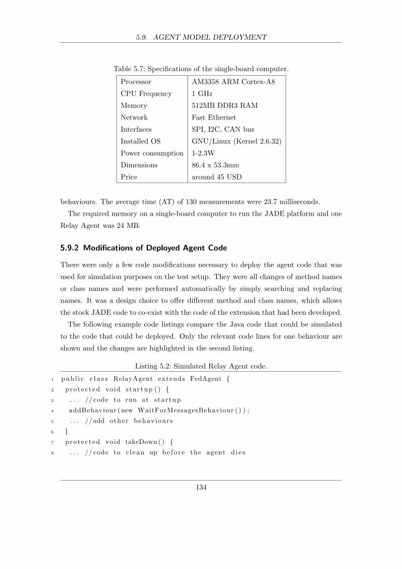
5.9. AGENT MODEL DEPLOYMENT
Table 5.7: Specifications of the single-board computer.
Processor AM3358 ARM Cortex-A8
CPU Frequency 1 GHz
Memory 512MB DDR3 RAM
Network Fast Ethernet
Interfaces SPI, I2C, CAN bus
Installed OS GNU/Linux (Kernel 2.6.32)
Power consumption 1-2.3W
Dimensions 86.4 x 53.3mm
Price around 45 USD
behaviours. The average time (AT) of 130 measurements were 23.7 milliseconds.
The required memory on a single-board computer to run the JADE platform and one
Relay Agent was 24 MB.
5.9.2 Modifications of Deployed Agent Code
There were only a few code modifications necessary to deploy the agent code that was
used for simulation purposes on the test setup. They were all changes of method names
or class names and were performed automatically by simply searching and replacing
names. It was a design choice to offer different method and class names, which allows
the stock JADE code to co-exist with the code of the extension that had been developed.
The following example code listings compare the Java code that could be simulated
to the code that could be deployed. Only the relevant code lines for one behaviour are
shown and the changes are highlighted in the second listing.
Listing 5.2: Simulated Relay Agent code.
1 pub l i c c l a s s RelayAgent extends FedAgent {2 protec ted void s ta r tup ( ) {3 . . . // code to run at s ta r tup
4 addBehaviour (new WaitForMessagesBehaviour ( ) ) ;
5 . . . //add other behaviours
6 }7 protec ted void takeDown ( ) {8 . . . // code to c l ean up be f o r e the agent d i e s
134

5.9. AGENT MODEL DEPLOYMENT
9 }10 }11 pub l i c c l a s s WaitForMessagesBehaviour extends Cycl icSimBehaviour {12 protec ted void ac t i on ( ) {13 . . . // the ac tua l code that i s executed f o r t h i s behaviour
14 sendSim (msg) ;
15 }16 protec ted double getProcess ingTime ( ) {17 // r e tu rn s the time to proce s s t h i s behaviour
18 }19 }
Listing 5.3: Deployed Relay Agent code.
1 pub l i c c l a s s RelayAgent extends Agent{2 protec ted void setup() {3 . . . // code to run at s ta r tup
4 addBehaviour (new WaitForMessagesBehaviour ( ) ) ;
5 . . . //add other behaviours
6 }7 protec ted void takeDown ( ) {8 . . . // code to c l ean up be f o r e the agent d i e s
9 }10 }11 pub l i c c l a s s WaitForMessagesBehaviour extends CyclicBehaviour {12 protec ted void ac t i on ( ) {13 . . . // the ac tua l code that i s executed f o r t h i s behaviour
14 send(msg) ;
15 }16 }
As can be seen in the listings, the only changes were class names the Relay Agents
and their behaviours were derived from (lines 1 and 11), the method which is run at
startup (line 2), and the method to send an agent message (line 14). The method that
returns the processing time (line 16) could either be removed or left in the code without
causing any issues because it simply would not be called. The only other change that is
not shown here was the use of either the System.currentTimeMilli() or getLocalTime()
method. The former returns the wall clock time for the deployed agent whereas the
135
5.9. AGENT MODEL DEPLOYMENT
latter is used during simulation to get the current simulation time.
Overall, these few changes do not alter the functionality and logic of the agent in any
way and could be carried out automatically.
5.9.3 General Requirements for Deployment
Although the deployment was tested with a particular hardware setup, it could have been
deployed on a wide range of computing devices. The only requirement is to provide the
Java 6 Runtime Environment (or higher) to be able to run the JADE platform (version
4.1 or higher). Obviously, there also needs to be enough computer memory available to
run the JADE platform with the agents and a network card to provide wired or wireless
communication.
For the developed protection scheme, it was assumed that the Relay Agents would
run directly on the relays. Considering the cheap but powerful computing hardware
of today and the low system requirements of a Java runtime environment and memory
requirements in the order of 24MB, it is a reasonable and technical feasible assumption.
The manufacturers of protection relays would have to provide this environment before
the protection system can be fully deployed as envisaged. Alternatively, the Relay
Agents can be deployed on separate hardware, such as the one used for the test setup,
and interface with the relays through external data buses or communication networks
depending on the relay models and their features. Many modern relays feature serial data
communication over fibre-optic cable, 2-wire connections, or IP-based communication
networks. For instance, the distance protection equipment of the Siemens SIPROTEC
series [115] can be extended by pluggable communication modules usable for different
and redundant protocols such as IEC 61850, IEC 60870-5-103, IEC 60870-5-104, and
DNP3 (both serial and through TCP).
The simulation and validation of this alternative deployment would have to reflect this
new setup. Although the developed system was not meant to be deployed in this way,
the simulations could be easily expanded to account for it. For example, the relays can
be modelled as additional agents in JADE to verify the correct communication between
them and the Relay Agents. They would also account for any time delays the relays
might add to the system performance. These models represent the physical relays and
are only used for the simulations and to validate the system before deployment.
136
5.10. SUMMARY
5.10 Summary
This chapter described the implementation and analysis of an agent-based remote backup
relay supervision scheme. The aim of the supervision scheme was to help prevent un-
necessary transmission line tripping due to hidden failures. It was developed for the
IEEE 39 bus system and was validated with the help of the MAC-Sim platform. Dif-
ferent application designs and communication technologies were analysed under various
communication network scenarios. Application designs included different peer selec-
tion algorithms and communication strategies such as client-server communication and
peer-to-peer communication. The impact of agent communication with different agent
message sizes and different transport protocols was assessed. Quality of Service (QoS)
strategies, background traffic, the impact of communication link outages, and additional
communication links were also considered in the scenarios. The obtained results showed
clearly that the communication infrastructure has a profound impact on the MAS per-
formance and clear recommendations were made on viable technologies and designs.
This chapter also identified the system requirements of MAC-Sim for the validation
of the supervision scheme. The computer memory and data storage requirements were
easily met with today’s computing equipment. Also, the measured simulation execution
times suggest that the time overhead added to the individual federates by the additionally
developed extensions, is negligible.
137
6 Conclusion
Multi-agent systems have been utilised to solve complex problems and build decen-
tralised, flexible, fault tolerant, and extensible systems. One area where MAS have
increasingly been applied to is the power industry. Massive research efforts are under-
way to design the new generation of power systems, often referred to as the Smart Grid.
It is the general vision to design the Smart Grid as a more decentralised system with
the availability of digital communication virtually everywhere. Multi-agent systems are
widely suggested as a promising method for the realisation of a wide variety of Smart
Grid applications such as power restoration, protection, and control. However, the de-
velopment and validation of deployable MAS has been challenging. Agent applications
make extensive use of digital communication, which influences the overall behaviour
and operation of the overall system by introducing additional time delays. Especially
delay-sensitive and time-critical applications need to be validated by methods that fully
account for the underlying communication infrastructure.
This research has presented a novel method for the accurate validation of multi-agent
systems. The validation accounts for the agent code, overall MAS functionality as well
as the impact of the underlying communication infrastructure. It therefore supports the
assessment of different applications, communication technologies, and scenarios.
In addition, an actual implementation, called MAC-Sim, has been presented that fed-
erates the FIPA-compliant Java Agent DEvelopment (JADE) platform and the network
simulator OPNET Modeler. The integration of the standard-based and well-established
tools meets the research aims in terms of compatibility with relevant agent standards
and features the tools offer. Also, the integration of JADE provides a platform for
agent-oriented software engineering, which was another requirement for this research. It
utilises a standardised distribution simulation modelling architecture, which offers open
interfaces that allow the integration of other tools in the future.
This work has addressed the challenges of federating existing tools that were not de-
signed for this purpose such as issues related to simulation interaction, synchronisation,
138
6.1. SUMMARY OF CONTRIBUTIONS
and data exchange between federates. As part of this effort, necessary extensions to
JADE and OPNET Modeler have been developed. The most notable of which include
the addition of discrete-event capabilities for JADE, a generic means to represent agent
applications within OPNET Modeler, and data exchange capabilities between the two
federates. Is has also been shown that the additional extensions have linear computa-
tional complexities, which suggests that they scale well.
Moreover, an agent-based backup relay supervision scheme has been developed for
the IEEE 39-bus system. Its performance has been analysed for different application
designs and communication technologies under different communication network scenar-
ios. Application designs included different peer selection algorithms and communication
strategies such as client-server communication and peer-to-peer communication. The
impact of various elements pertaining to agent communication have been included such
as different message sizes and transport protocols. Also, Quality of Service (QoS) strate-
gies, background traffic, the impact of communication link outages as well as additional
links have been considered. The obtained results show clearly that the communication
infrastructure has a profound impact on the MAS performance and therefore it is critical
to account for it during MAS development. Based on the results, clear recommenda-
tions on viable technologies and designs have been made. The validated MAS code has
successfully been deployed on a small scale which proves that the suggested method also
supports the deployment and is not only a tool for validation through simulation.
It has also been shown that the computer memory and storage requirements for the
validation of the supervision scheme was easily met with the computing equipment that
is readily available today. Furthermore, the obtained simulation results suggest that the
time overhead added to the individual federates by the additionally developed extensions
is negligible.
In conclusion, a new method for MAS development and validation has been presented
which provides a means to rapidly implement agent-based applications and accurately
validate them for different communication technologies.
6.1 Summary of Contributions
During the course of this research several significant contributions have been made:
• A new method has been suggested that enables the development and validation
139
6.2. FUTURE WORK
of MAS that accurately accounts for the influence of converged communication
networks. The method allows for a direct deployment of the validated MAS code.
• A software platform has been implemented that demonstrates the new method. Its
development tackled simulation interfacing issues by providing new ways to add
(a) discrete-event capabilities to a multi-agent system framework, (b) a generic
means to represent agent applications within a network simulator, and (c) data
exchange capabilities between the framework and the network simulator.
• A case study of the implementation and validation of an agent-based remote backup
relay supervision scheme has been presented. It shows the significant influence of
agent design and communication network technologies on the MAS performance
and therefore importance and usefulness of the newly proposed method. The
validated multi-agent system code has been shown to be directly deployable.
• Publications in relevant research areas:
F. Perkonigg, D. Brujic, and M Ristic. Platform for development and validation
agent-based smart grid applications incorporating accurate communications mod-
elling. Industrial Informatics, IEEE Transactions on, PP(99):1–1, 2014. ISSN
0885-8977. Under Review
F. Perkonigg, D. Brujic, and M. Ristic. Mac-sim: A multi-agent and communication
network simulation platform for smart grid applications based on established tech-
nologies. In Smart Grid Communications (SmartGridComm), 2013 IEEE Inter-
national Conference on, pages 570–575, Oct 2013. doi: 10.1109/SmartGridComm.
2013.6688019
F. Perkonigg and M Ristic. A multi-agent and communication network simulation
platform based on established standards. In HubNet Smart Grids Symposium,
September 2012
6.2 Future Work
This last section describes open issues and discusses ideas for future work that can extend
the one presented in this thesis.
The presented co-simulation platform federates a multi-agent system framework and
network simulator, but additional simulation tools are needed for more involved appli-
140
6.2. FUTURE WORK
cations. For example, multi-agent applications that influence the operation of power
systems also require the integration of power system simulations for accurate validation.
Tools such as Positive Sequence Load Flow (PSLF) software, PSCAD/EMTDC elec-
tromagnetic transient simulators, the Virtual Test Bed (VTB), and the MATPOWER
MATLAB package could be added to the platform via the standardised RTI interface.
Previous research has shown that these tools can be federated with other event-driven
or time-stepped systems [74, 85, 88, 89] (see section 2.5).
Another area that needs further investigation is the question of how software agents
developed with the presented method can interact with other entities that are not agents.
Currently JADE only supports agent communication that is based on the standardised
FIPA Agent Communication Language (ACL). While this is not a problem for inter-agent
communication, it limits agent interactions with other entities such as power protection
and control devices in substations. An increasing number of these devices implement the
IEC 61850 standard, which defines aspects of power system communication for electrical
substation automation [119, 120]. The integration of relevant parts of the standard into
JADE would allow agents to communicate directly with devices in substations without
the need to use proprietary interfaces. There are open source implementation of the
standard available [121, 122], which could be modified for JADE.
141
Bibliography
[1] Seth Blumsack and Alisha Fernandez. Ready or not, here comes the smart
grid! Energy, 37(1):61 – 68, 2012. ISSN 0360-5442. doi: 10.1016/j.
energy.2011.07.054. URL http://www.sciencedirect.com/science/article/
pii/S0360544211005287. 7th Biennial International Workshop Advances in En-
ergy Studies.
[2] F. Ren, M. Zhang, D. Soetanto, and X. Su. Conceptual design of a multi-agent
system for interconnected power systems restoration. Power Systems, IEEE Trans-
actions on, 27(2):732 –740, May 2012. ISSN 0885-8950. doi: 10.1109/TPWRS.
2011.2177866.
[3] T. Nagata, H. Watanabe, M. Ohno, and H. Sasaki. A multi-agent approach to
power system restoration. In Proc. Int. Conf. Power System Technology PowerCon
2000, volume 3, pages 1551–1556, 2000. doi: 10.1109/ICPST.2000.898202.
[4] J.M. Solanki, S. Khushalani, and N.N. Schulz. A multi-agent solution to distri-
bution systems restoration. Power Systems, IEEE Transactions on, 22(3):1026
–1034, Aug 2007. ISSN 0885-8950. doi: 10.1109/TPWRS.2007.901280.
[5] D. V. Coury, J. S. Thorp, K. M. Hopkinson, and K. P. Birman. An agent-based
current differential relay for use with a utility intranet. IEEE Transactions on
Power Delivery, 17(1):47–53, 2002. doi: 10.1109/61.974186.
[6] S.D.J. McArthur, E.M. Davidson, J.A. Hossack, and J.R. McDonald. Automating
power system fault diagnosis through multi-agent system technology. In System
Sciences, 2004. Proceedings of the 37th Annual Hawaii International Conference
on, page 8 pp., Jan 2004. doi: 10.1109/HICSS.2004.1265190.
[7] J. Hossack, S.D.J. McArthur, J.R. McDonald, J. Stokoe, and T. Cumming. A
multi-agent approach to power system disturbance diagnosis. In Power System
142
Bibliography
Management and Control, 2002. Fifth International Conference on (Conf. Publ.
No. 488), pages 317 – 322, April 2002. doi: 10.1049/cp:20020055.
[8] H.F. Wang. Multi-agent co-ordination for the secondary voltage control in
power-system contingencies. Generation, Transmission and Distribution, IEE
Proceedings-, 148(1):61 –66, Jan 2001. ISSN 1350-2360. doi: 10.1049/ip-gtd:
20010025.
[9] A. L. Dimeas and N. D. Hatziargyriou. Operation of a multiagent system for
microgrid control. IEEE Transactions on Power Systems, 20(3):1447–1455, 2005.
doi: 10.1109/TPWRS.2005.852060.
[10] A. L. Dimeas and N. D. Hatziargyriou. Agent based control for microgrids. In
Proc. IEEE Power Engineering Society General Meeting, pages 1–5, 2007. doi:
10.1109/PES.2007.386064.
[11] S. Karnouskos and T.N. de Holanda. Simulation of a smart grid city with software
agents. In Computer Modeling and Simulation, 2009. EMS ’09. Third UKSim
European Symposium on, pages 424 –429, Nov 2009. doi: 10.1109/EMS.2009.53.
[12] Miroslav Prymek, Ales Horak, Radomr Gono, and Stanislav Rusek. Power distri-
bution network reliability modeling based on the statistical data and multi-agent
simulation. In Brno, Czech Republic : Brno University of Technology, 2008, 2008.
[13] Radwan Tahboub, Dan Lazarescu, and Vasile Lazarescu. Modeling and simulation
of secure automatic energy meter reading and management systems using mobile
agents. International Journal of Computer Science and Network Security, 7:1, Jan
2007.
[14] I. Praca, C. Ramos, Z. Vale, and M. Cordeiro. Mascem: a multiagent system that
simulates competitive electricity markets. Intelligent Systems, IEEE, 18(6):54–60,
2003. ISSN 1541-1672. doi: 10.1109/MIS.2003.1249170.
[15] Michael Woolridge and Michael J. Wooldridge. Introduction to Multiagent Systems.
John Wiley & Sons, Inc., New York, NY, USA, 2001. ISBN 047149691X. URL
http://lib.myilibrary.com/Open.aspx?id=26978&src=0.
[16] Yoav Shoham. Agent-oriented programming. Artificial Intelligence, 60:51–92,
1991.
143
Bibliography
[17] Andrea Omicini Franco Zambonelli. Challenges and research directions in agent-
oriented software engineering. Autonomous Agents and Multi-Agent Sytems, 9:
253283, 2004.
[18] Rob Allan. Survey of agent based modelling and simulation tools. Engineering,
501(October):57–72, 2009. URL http://epubs.cclrc.ac.uk/epub/bitstream/
5601/DLTR-2010-007.pdf.
[19] FIPA. Foundation for intelligent physical agents. URL http://www.fipa.org.
[20] Foundation for Intelligent Physical Agents. Standard fipa specifications. online, .
URL http://www.fipa.org/repository/standardspecs.html.
[21] Foundation for Intelligent Physical Agents. Fipa agent management specification.
online, . URL http://www.fipa.org/specs/fipa00023/index.html.
[22] Foundation for Intelligent Physical Agents. Fipa acl message structure specifica-
tion. online, . URL http://www.fipa.org/specs/fipa00061/SC00061G.html.
[23] FIPA. Publicly available agent platform implementations. URL http://fipa.
org/resources/livesystems.html.
[24] JADE. Java agent development framework. online. URL http://jade.tilab.com.
[25] Zeus. online, . URL http://labs.bt.com/projects/agents/zeus.
[26] AOS Group. Jack. online, . URL http://www.agent-software.com/.
[27] Michal Laclavik, Stefan Dlugolinsky, Martin Seleng, Marcel Kvassay, Bernhard
Schneider, Holger Bracker, Michal Wrzeszcz, Jacek Kitowski, and Ladislav Hluchy.
Agent-based simulation platform evaluation in the context of human behavior mod-
eling. In ITMAS 2011 Workshop at AAMAS 2011, Taipei, Taiwan, 2011.
[28] Elhadi Shakshuki and Yang Jun. Multi-agent development toolkits: An evaluation.
In Bob Orchard, Chunsheng Yang, and Moonis Ali, editors, Innovations in Applied
Artificial Intelligence, volume 3029 of Lecture Notes in Computer Science, pages
209–218. Springer Berlin / Heidelberg, 2004. ISBN 978-3-540-22007-7. URL http:
//dx.doi.org/10.1007/978-3-540-24677-0/23.
144

Bibliography
[29] R. Trillo, S. Ilarri, and E. Mena. Comparison and performance evaluation of mobile
agent platforms. In Autonomic and Autonomous Systems, 2007. ICAS07. Third
International Conference on, page 41, June 2007. doi: 10.1109/CONIELECOMP.
2007.66.
[30] D. Camacho, R. Aler, C. Castro, and J.M. Molina. Performance evaluation of
zeus, jade, and skeletonagent frameworks. In Systems, Man and Cybernetics, 2002
IEEE International Conference on, volume 4, page 6 pp. vol.4, Oct 2002. doi:
10.1109/ICSMC.2002.1173303.
[31] U.S. Department of Energy. Smart grid. online. URL http://energy.gov/oe/
services/technology-development/smart-grid.
[32] SUPERGEN. Supergen highly distributed energy future (HiDEF). online. URL
http://www.supergen-hidef.info.
[33] SmartGrids. Smartgrids - European technology platform for the electricity net-
works of the future. URL http://www.smartgrids.eu/.
[34] EPRI. Intelligrid. URL http://intelligrid.epri.com/.
[35] CRISP. Distributed intelligence in critical infrastructures for sustainable power.
URL http://www.crisp.ecn.nl/.
[36] S. D. J. McArthur, E. M. Davidson, V. M. Catterson, A. L. Dimeas, N. D. Hatziar-
gyriou, F. Ponci, and T. Funabashi. Multi-agent systems for power engineering
applications—part i: Concepts, approaches, and technical challenges. IEEE Trans-
actions on Power Systems, 22(4):1743–1752, 2007. doi: 10.1109/TPWRS.2007.
908471.
[37] S. D. J. McArthur, E. M. Davidson, V. M. Catterson, A. L. Dimeas, N. D. Hatziar-
gyriou, F. Ponci, and T. Funabashi. Multi-agent systems for power engineering
applications—part ii: Technologies, standards, and tools for building multi-agent
systems. IEEE Transactions on Power Systems, 22(4):1753–1759, 2007. doi:
10.1109/TPWRS.2007.908472.
[38] Amar Patel, Juan Aparicio, Nazif Tas, Michael Loiacono, and Justinian Rosca.
Assessing communications technology options for smart grid applications. In IEEE
SmartGridComm2011, 2011.
145
Bibliography
[39] BBC. Saving the planet one gadget at a time, 2010. URL http://news.bbc.co.
uk/go/pr/fr/-/1/hi/programmes/click_online/9045392.stm.
[40] BBC. Smart meters may not cut energy use. online, September 2010. URL
http://www.bbc.com/news/science-environment-11199771.
[41] Husheng Li, Zhu Han, Lifeng Lai, R.C. Qiu, and Depeng Yang. Efficient and
reliable multiple access for advanced metering in future smart grid. In Smart
Grid Communications (SmartGridComm), 2011 IEEE International Conference
on, pages 440–444, Oct 2011. doi: 10.1109/SmartGridComm.2011.6102363.
[42] Viktorija Namavira and Tom Hainey. High-level smart meter data traffic anal-
ysis. online, May 2010. URL http://www.energynetworks.org/electricity/
futures/smart-meters.html.
[43] D.G. Hart. Using ami to realize the smart grid. In Power and Energy Society Gen-
eral Meeting - Conversion and Delivery of Electrical Energy in the 21st Century,
2008 IEEE, pages 1–2, July 2008. doi: 10.1109/PES.2008.4596961.
[44] F. Brazier, F. Cornelissen, R. Gustavsson, C. M. Jonker, O. Lindeberg, B. Polak,
and J. Treur. Agents negotiating for load balancing of electricity use. In Proc.
18th Int Distributed Computing Systems Conf, pages 622–629, 1998. doi: 10.1109/
ICDCS.1998.679850.
[45] Weihao Hu, Zhe Chen, and B. Bak-Jensen. Optimal load response to time-of-
use power price for demand side management in denmark. In Power and Energy
Engineering Conference (APPEEC), 2010 Asia-Pacific, pages 1 –4, 2010. doi:
10.1109/APPEEC.2010.5448730.
[46] Z. Zhou, F. Zhao, and J. Wang. Agent-based electricity market simulation with
demand response from commercial buildings. IEEE Transactions on Smart Grid,
2(4):580–588, 2011. doi: 10.1109/TSG.2011.2168244.
[47] Ioannis S. Baxevanos and Dimitris P. Labridis. Implementing multiagent sys-
tems technology for power distribution network control and protection man-
agement. IEEE Transactions on Power Delivery, 22(1):433–443, 2007. doi:
10.1109/TPWRD.2006.877085.
146
Bibliography
[48] D.V. Coury, J.S. Thorp, K.M. Hopkinson, and K.P. Birman. Agent technology
applied to adaptive relay setting for multi-terminal lines. In Power Engineering
Society Summer Meeting, 2000. IEEE, volume 2, pages 1196 –1201 vol. 2, 2000.
doi: 10.1109/PESS.2000.867549.
[49] S. Garlapati, Hua Lin, S. Sambamoorthy, S.K. Shukla, and J. Thorp. Agent based
supervision of zone 3 relays to prevent hidden failure based tripping. In Smart Grid
Communications (SmartGridComm), 2010 First IEEE International Conference
on, pages 256 –261, Oct. 2010. doi: 10.1109/SMARTGRID.2010.5622051.
[50] Thomas Baldwin, Stevens McVoy, and Charles Steinfield. Convergence: Integrating
Media, Information & Communication. SAGE Publications, Inc, 1996.
[51] V. C. Gungor, D. Sahin, T. Kocak, S. Ergut, C. Buccella, C. Cecati, and G. P.
Hancke. Smart grid technologies: Communication technologies and standards.
IEEE Transactions on Industrial Informatics, 7(4):529–539, 2011. doi: 10.1109/
TII.2011.2166794.
[52] European Commission. ICT for a Low Carbon Economy - Smart Electricity Dis-
tribution Networks. Office for Official Publications of the European Communities,
2009.
[53] Cherry Yuen, Romeo Comino, Mathias Kranich, Dave Laurenson, and Javier Bar-
ria. The role of communication to enable smart distribution applications. In Elec-
tricity Distribution - Part 1, 2009. CIRED 2009. 20th International Conference
and Exhibition on, pages 1 –4, June 2009.
[54] C. H. Hauser, D. E. Bakken, and A. Bose. A failure to communicate: next
generation communication requirements, technologies, and architecture for the
electric power grid. IEEE Power and Energy Magazine, 3(2):47–55, 2005. doi:
10.1109/MPAE.2005.1405870.
[55] Kwok-Hong Mak and B. L. Holland. Migrating electrical power network scada
systems to tcp/ip and ethernet networking. Power Engineering Journal, 16(6):
305–311, 2002. doi: 10.1049/pej:20020604.
[56] Qiang Yang and J.A. Barria. ICT systems for managing medium voltage active
147

Bibliography
distribution grids. In Industrial Electronics, 2009. IECON ’09. 35th Annual Con-
ference of IEEE, pages 3581 –3586, Nov 2009. doi: 10.1109/IECON.2009.5415156.
[57] Qiang Yang, J.A. Barria, and C.A.H. Aramburo. A communication system archi-
tecture for regional control of power distribution networks. In Industrial Informat-
ics, 2009. INDIN 2009. 7th IEEE International Conference on, pages 372 –377,
June 2009. doi: 10.1109/INDIN.2009.5195833.
[58] Q. Yang, J. A. Barria, and T. C. Green. Communication infrastructures for dis-
tributed control of power distribution networks. IEEE Transactions on Industrial
Informatics, 7(2):316–327, 2011. doi: 10.1109/TII.2011.2123903.
[59] Jerry Banks, John S. Carson, Barry L. Nelson, and David M. Nicol. Discrete-Event
System Simulation (5th Edition). Pearson, 5 edition, 2010. ISBN 0136062121. URL
http://www.worldcat.org/isbn/0136062121.
[60] R. E. Shannon. Introduction to the art and science of simulation. In Proc. Winter
Simulation, volume 1, pages 7–14, 1998. doi: 10.1109/WSC.1998.744892.
[61] R.G. Ingalls. Introduction to simulation. In Simulation Conference, 2002. Pro-
ceedings of the Winter, volume 1, pages 7–16 vol.1, Dec 2002. doi: 10.1109/WSC.
2002.1172861.
[62] Teerawat Issariyakul and Ekram Hossain. Introduction to Network Simulator NS2.
Springer, 2009. ISBN 978-0-387-71759-3. doi: 10.1007/978-0-387-71760-9. URL
http://www.springer.com/engineering/signals/book/978-0-387-71759-3.
[63] NS2. Network simulator 2. URL http://www.isi.edu/nsnam/ns/.
[64] NS3. Network simulator 3. URL http://www.nsnam.org/.
[65] Qualnet, . URL http://www.scalable-networks.com/content/products/
qualnet.
[66] OMNETST. Omnet++. URL http://omnetpp.org/.
[67] Renesys. Ssfnet. URL http://www.ssfnet.org/.
[68] TETCOS. Netsim. online. URL http://www.tetcos.com/netsim_gen.html.
148

Bibliography
[69] Riverbed. OPNET Modeler. URL http://www.opnet.com/solutions/network_
rd/modeler.html.
[70] J. Postel and J. Reynolds. File transfer protocol (ftp). online, October 1985. URL
https://www.ietf.org/rfc/rfc959.txt.
[71] R. Fielding, J. Gettys, J. Mogul, H. Frystyk, L. Masinter, P. Leach, and T. Berners-
Lee. Hypertext transfer protocol. online, June 1999. URL https://www.ietf.
org/rfc/rfc2616.txt.
[72] M. Pipattanasomporn, H. Feroze, and S. Rahman. Multi-agent systems in a
distributed smart grid: Design and implementation. In Power Systems Confer-
ence and Exposition, 2009. PSCE ’09. IEEE/PES, pages 1 –8, March 2009. doi:
10.1109/PSCE.2009.4840087.
[73] R.A. Dougal, S. Liu, L. Gao, and M. Blackwelder. Virtual test bed for advanced
power sources. Journal of Power Sources, 110(2):285 – 294, 2002. ISSN 0378-
7753. doi: http://dx.doi.org/10.1016/S0378-7753(02)00191-X. URL http://www.
sciencedirect.com/science/article/pii/S037877530200191X.
[74] Hua Lin, S.S. Veda, S.S. Shukla, L. Mili, and J. Thorp. Geco: Global event-driven
co-simulation framework for interconnected power system and communication net-
work. Smart Grid, IEEE Transactions on, 3(3):1444–1456, 2012. ISSN 1949-3053.
doi: 10.1109/TSG.2012.2191805.
[75] Hua Lin, S. Sambamoorthy, S. Shukla, J. Thorp, and L. Mili. Power system and
communication network co-simulation for smart grid applications. In Innovative
Smart Grid Technologies (ISGT), 2011 IEEE PES, pages 1 –6, Jan 2011. doi:
10.1109/ISGT.2011.5759166.
[76] Yan He, N. Jenkins, Jianzhong Wu, and M. Eltayeb. Ict infrastructure for smart
distribution networks. In Proc. IEEE Int Power Line Communications and Its Ap-
plications (ISPLC) Symp, pages 319–324, 2010. doi: 10.1109/ISPLC.2010.5479911.
[77] Terence Song, Dritan Kaleshi, Ran Zhou, Olivier Boudeville, Jing-Xuan Ma, Aude
Pelletier, and Idir Haddadi. Performance evaluation of integrated smart energy
solutions through large-scale simulations. In SmartGridComm2011, 2011.
149

Bibliography
[78] Ian Taylor, Brian Adamson, Ian Downard, and Joe Macker. Agentj: Enabling java
ns-2 simulations for large scale distributed multimedia applications. In Proc. 2nd
Int Distributed Frameworks for Multimedia Applications Conf, pages 1–7, 2006.
doi: 10.1109/DFMA.2006.296911.
[79] Java native interface specification. online, . URL http://docs.oracle.com/
javase/7/docs/technotes/guides/jni/spec/jniTOC.html.
[80] X. Wang, P. Zhang, Z. Wang, V. Dinavahi, G. Chang, J.A. Martinez, A. Davoudi,
A. Mehrizi-Sani, and S. Abhyankar. Interfacing issues in multiagent simulation
for smart grid applications. Power Delivery, IEEE Transactions on, PP(99):1–1,
2013. ISSN 0885-8977. doi: 10.1109/TPWRD.2013.2260566.
[81] IEEE Computer Society. IEEE Standard for Modeling and Simulation High Level
Architecture (HLA)– Federate Interface Specification. Number ISBN 978-0-7381-
6248-5. The Institute of Electrical and Electronics Engineers, Inc., 2010. doi:
10.1109/IEEESTD.2010.5557728.
[82] Steffen Straburger. On the hla-based coupling of simulation tools. online, 1999.
URL http://isgsim1.cs.uni-magdeburg.de/hla/paper/HLASimTools.pdf.
[83] C. McLean and F. Riddick. The ims mission architecture for distributed manufac-
turing simulation. In Simulation Conference, 2000. Proceedings. Winter, volume 2,
pages 1539–1548 vol.2, 2000. doi: 10.1109/WSC.2000.899138.
[84] S.J.R. Taylor, R. Sudra, T. Janahan, G. Tan, and J. Ladbrook. Towards cots
distributed simulation using grids. In Simulation Conference, 2001. Proceedings
of the Winter, volume 2, pages 1372–1379 vol.2, 2001. doi: 10.1109/WSC.2001.
977458.
[85] W. Li, A Monti, M. Luo, and R.A Dougal. Vpnet: A co-simulation framework
for analyzing communication channel effects on power systems. In Electric Ship
Technologies Symposium (ESTS), 2011 IEEE, pages 143–149, April 2011. doi:
10.1109/ESTS.2011.5770857.
[86] V. Liberatore and A Al-Hammouri. Smart grid communication and co-simulation.
In Energytech, 2011 IEEE, pages 1–5, May 2011. doi: 10.1109/EnergyTech.2011.
5948542.
150
Bibliography
[87] Giuseppe Iazeolla Daniele Gianni, Andrea D’Ambrogio and Alessandra
Pieroni. HLA-Transparent Distributed Simulation of Agent-based Systems.
InTech, 2010. URL http://www.intechopen.com/articles/show/title/
hla-transparent-distributed-simulation-of-agent-based-systems.
[88] K. Hopkinson, Xiaoru Wang, R. Giovanini, J. Thorp, K. Birman, and D. Coury.
Epochs: a platform for agent-based electric power and communication simulation
built from commercial off-the-shelf components. IEEE Transactions on Power
Systems, 21(2):548–558, 2006. doi: 10.1109/TPWRS.2006.873129.
[89] G. Morejon, S. K. Srivastava, and D. A. Cartes. Integrating virtual test bed and
jade agent platform using corba for reconfiguration of shipboard power systems.
In Proc. IEEE Power Engineering Society General Meeting, 2006. doi: 10.1109/
PES.2006.1709015.
[90] A. Buss and L. Jackson. Distributed simulation modeling: a comparison of hla,
corba, and rmi. In Proc. Winter Simulation, volume 1, pages 819–825, 1998. doi:
10.1109/WSC.1998.745071.
[91] Frederick Kuhl, Richard Weatherly, and Judith Dahmann. Creating Computer
Simulation Systems: An Introduction to the High Level Architecture (Book only).
Prentice Hall PTR, October 1999. ISBN 0130225118. URL http://www.amazon.
com/exec/obidos/redirect?tag=citeulike07-20&path=ASIN/0130225118.
[92] Object Management Group. Corba website. online, . URL http://www.corba.
org/.
[93] Oracle. Java remote method invocation. online. URL http://docs.oracle.com/
javase/6/docs/technotes/guides/rmi/index.html.
[94] IEEE. IEEE standard for modeling and simulation high level architecture (HLA)–
framework and rules. IEEE Std 1516-2010 (Revision of IEEE Std 1516-2000),
IEEE Std 1516-201:1 –38, 18 2010. doi: 10.1109/IEEESTD.2010.5553440.
[95] IEEE Computer Society. IEEE standard for modeling and simulation high level
architecture (HLA)– object model template (OMT) specification. The Institute
of Electrical and Electronics Engineers, Inc., 1(1516.2-2010 (Revision of 1516.2-
2000)):1–112, 2010. doi: 10.1109/IEEESTD.2010.5557731.
151

Bibliography
[96] IEEE recommended practice for high level architecture (HLA) federation develop-
ment and execution process (FEDEP), 2003.
[97] Richard M. Fujimoto. Time management in the high level architecture. Simulation,
71:388–400, 1998.
[98] Shekar Nethi, Mikael Pohjola, Lasse Eriksson, and Riku Jantti. Platform for
emulating networked control systems in laboratory environments. In Proc. IEEE
Int. Symp. a World of Wireless, Mobile and Multimedia Networks WoWMoM 2007,
pages 1–8, 2007. doi: 10.1109/WOWMOM.2007.4351727.
[99] Dirk Pawlaszczyk and Ingo J. Timm. A hybrid time management approach to
agent-based simulation. In 29th Annual German Conference on Artificial Intelli-
gence (KI 2006), pages 374–388, 2006.
[100] R. M. Fujimoto. Parallel and distributed simulation systems. In Proc. Winter
Simulation Conf, volume 1, pages 147–157, 2001. doi: 10.1109/WSC.2001.977259.
[101] VT MK. HLA RTI run time infrastructure: MK RTI, 2014. URL
http://www.mak.com/products/link-simulation-interoperability/
hla-rti-run-time-infrastructure.html.
[102] Portico. The poRTIco project. URL http://www.porticoproject.org/.
[103] CERTI Project. CERTI open source HLA RTI. URL http://savannah.nongnu.
org/projects/certi/.
[104] K. Chmiel, D. Tomiak, M. Gawinecki, P. Karczmarek, M. Szymczak, and M. Pa-
przycki. Testing the efficiency of jade agent platform. In Proc. Third Int Parallel
and Distributed Computing Third Int. Symp. /Algorithms, Models and Tools for
Parallel Computing Heterogeneous Networks Workshop, pages 49–56, 2004. doi:
10.1109/ISPDC.2004.49.
[105] A. L. Dimeas and N. D. Hatziargyriou. Agent based control of virtual power plants.
In Proc. Int. Conf. Intelligent Systems Applications to Power Systems ISAP 2007,
pages 1–6, 2007. doi: 10.1109/ISAP.2007.4441671.
[106] Fabio Luigi Bellifemine, Giovanni Caire, and Dominic Greenwood. Developing
Multi-Agent Systems with JADE (Wiley Series in Agent Technology). John Wiley
& Sons, 2007. ISBN 0470057475.
152
Bibliography
[107] Open systems interconnection - basic reference model: The basic model, . URL
http://www.itu.int/rec/T-REC-X/en.
[108] Information Sciences Institute University of Southern California. Transmission
control protocol - protocol specification. online, Sep 1981. URL http://www.
ietf.org/rfc/rfc793.txt.
[109] J. Postel. User datagram protocol. online, Aug 1980. URL http://www.ietf.
org/rfc/rfc768.txt.
[110] L. Ong and J. Yoakum. An introduction to the stream control transmission pro-
tocol (sctp). online, May 2002. URL http://www.ietf.org/rfc/rfc3286.txt.
[111] Arun G. Phadke. Hidden failures in electric power systems. International Jour-
nal of Critical Infrastructures, 1(1):64–75, 2004. doi: doi:10.1504/IJCIS.2004.
003796. URL http://www.ingentaconnect.com/content/ind/ijcis/2004/
00000001/00000001/art00004.
[112] A.G. Phadke and J.S. Thorp. Expose hidden failures to prevent cascading outages
[in power systems]. Computer Applications in Power, IEEE, 9(3):20–23, Jul 1996.
ISSN 0895-0156. doi: 10.1109/67.526849.
[113] S. Blake, D. Black, M. Carlson, E. Davies, Z. Wang, and W. Weiss. An architecture
for differentiated services. online, Dec 1998. URL http://www.ietf.org/rfc/
rfc2475.txt.
[114] Grenville Armitage. Quality of Service in IP Networks: Foundations for a Multi-
service Internet. Macmillan Publishing Co., Inc., Indianapolis, IN, USA, 2000.
ISBN 1-57870-189-9.
[115] Siemens. Distance protection. online. URL https://w3.siemens.
com/smartgrid/global/en/products-systems-solutions/Protection/
distance-protection/Pages/overview.aspx.
[116] F. Perkonigg, D. Brujic, and M Ristic. Platform for development and validation
agent-based smart grid applications incorporating accurate communications mod-
elling. Industrial Informatics, IEEE Transactions on, PP(99):1–1, 2014. ISSN
0885-8977. Under Review.
153
Bibliography
[117] F. Perkonigg, D. Brujic, and M. Ristic. Mac-sim: A multi-agent and communi-
cation network simulation platform for smart grid applications based on estab-
lished technologies. In Smart Grid Communications (SmartGridComm), 2013
IEEE International Conference on, pages 570–575, Oct 2013. doi: 10.1109/
SmartGridComm.2013.6688019.
[118] F. Perkonigg and M Ristic. A multi-agent and communication network simulation
platform based on established standards. In HubNet Smart Grids Symposium,
September 2012.
[119] C. Brunner. Iec 61850 for power system communication. In Proc. T&D Trans-
mission and Distribution Conf. and Exposition IEEE/PES, pages 1–6, 2008. doi:
10.1109/TDC.2008.4517287.
[120] R.E. Mackiewicz. Overview of iec 61850 and benefits. In Transmission and Dis-
tribution Conference and Exhibition, 2005/2006 IEEE PES, pages 376 –383, May
2006. doi: 10.1109/TDC.2006.1668522.
[121] Openmuc project. online, . URL http://openmuc.org/.
[122] Open source library for iec 61850. online, . URL http://libiec61850.com/
libiec61850/.
154
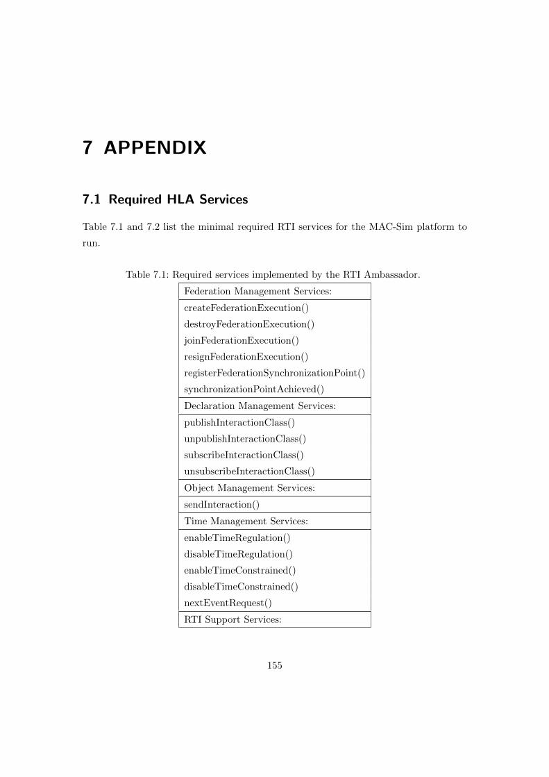
7 APPENDIX
7.1 Required HLA Services
Table 7.1 and 7.2 list the minimal required RTI services for the MAC-Sim platform to
run.
Table 7.1: Required services implemented by the RTI Ambassador.
Federation Management Services:
createFederationExecution()
destroyFederationExecution()
joinFederationExecution()
resignFederationExecution()
registerFederationSynchronizationPoint()
synchronizationPointAchieved()
Declaration Management Services:
publishInteractionClass()
unpublishInteractionClass()
subscribeInteractionClass()
unsubscribeInteractionClass()
Object Management Services:
sendInteraction()
Time Management Services:
enableTimeRegulation()
disableTimeRegulation()
enableTimeConstrained()
disableTimeConstrained()
nextEventRequest()
RTI Support Services:
155

7.2. AGENT TOPOLOGY OF THE IEEE 39 BUS SYSTEM
getAttributeHandle()
getAttributeName()
getInteractionClassHandle()
getInteractionClassName()
getParameterHandle()
getParameterName()
tick()
Table 7.2: Required services implemented by the Federate Ambassador
Federation Management Services:
synchronizationPointRegistrationFailed()
synchronizationPointRegistrationSucceeded()
announceSynchronizationPoint()
federationSynchronized()
Object Management Services:
discoverObjectInstance()
reflectAttributeValues()
receiveInteraction()
removeObjectInstance()
Time Management Services:
timeRegulationEnabled()
timeConstrainedEnabled()
timeAdvanceGrant()
7.2 Agent Topology of the IEEE 39 bus system
Table 7.3: Table describing the agent topology of the IEEE 39 bus system.
Line Zone 1 Zone 2 Zone 3
P001 001-002
002-001
030-002 025-002 003-
002 039-001
037-025 026-025 018-003 004-003
009-039
156
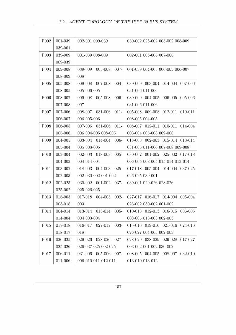
7.2. AGENT TOPOLOGY OF THE IEEE 39 BUS SYSTEM
P002 001-039
039-001
002-001 009-039 030-002 025-002 003-002 008-009
P003 039-009
009-039
001-039 008-009 002-001 005-008 007-008
P004 009-008
008-009
039-009 005-008 007-
008
001-039 004-005 006-005 006-007
P005 005-008
008-005
009-008 007-008 004-
005 006-005
039-009 003-004 014-004 007-006
031-006 011-006
P006 008-007
007-008
009-008 005-008 006-
007
039-009 004-005 006-005 005-006
031-006 011-006
P007 007-006
006-007
008-007 031-006 011-
006 005-006
005-008 009-008 012-011 010-011
008-005 004-005
P008 006-005
005-006
007-006 031-006 011-
006 004-005 008-005
008-007 012-011 010-011 014-004
003-004 005-008 009-008
P009 004-005
005-004
003-004 014-004 006-
005 008-005
018-003 002-003 015-014 013-014
031-006 011-006 007-008 009-008
P010 003-004
004-003
002-003 018-003 005-
004 014-004
030-002 001-002 025-002 017-018
006-005 008-005 015-014 013-014
P011 003-002
002-003
018-003 004-003 025-
002 030-002 001-002
017-018 005-004 014-004 037-025
026-025 039-001
P012 002-025
025-002
030-002 001-002 037-
025 026-025
039-001 029-026 028-026
P013 018-003
003-018
017-018 004-003 002-
003
027-017 016-017 014-004 005-004
025-002 030-002 001-002
P014 004-014
014-004
013-014 015-014 005-
004 003-004
010-013 012-013 016-015 006-005
008-005 018-003 002-003
P015 017-018
018-017
016-017 027-017 003-
018
015-016 019-016 021-016 024-016
026-027 004-003 002-003
P016 026-025
025-026
029-026 028-026 027-
026 037-025 002-025
028-029 038-029 029-028 017-027
003-002 001-002 030-002
P017 006-011
011-006
031-006 005-006 007-
006 010-011 012-011
008-005 004-005 008-007 032-010
013-010 013-012
157
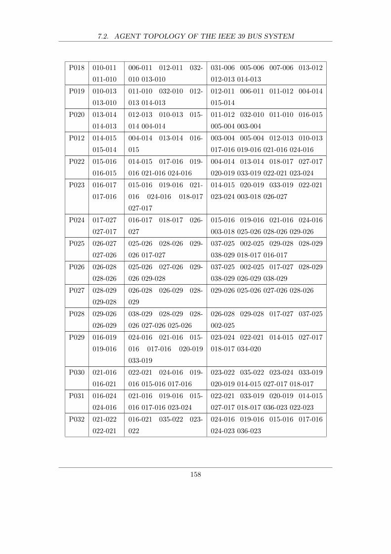
7.2. AGENT TOPOLOGY OF THE IEEE 39 BUS SYSTEM
P018 010-011
011-010
006-011 012-011 032-
010 013-010
031-006 005-006 007-006 013-012
012-013 014-013
P019 010-013
013-010
011-010 032-010 012-
013 014-013
012-011 006-011 011-012 004-014
015-014
P020 013-014
014-013
012-013 010-013 015-
014 004-014
011-012 032-010 011-010 016-015
005-004 003-004
P012 014-015
015-014
004-014 013-014 016-
015
003-004 005-004 012-013 010-013
017-016 019-016 021-016 024-016
P022 015-016
016-015
014-015 017-016 019-
016 021-016 024-016
004-014 013-014 018-017 027-017
020-019 033-019 022-021 023-024
P023 016-017
017-016
015-016 019-016 021-
016 024-016 018-017
027-017
014-015 020-019 033-019 022-021
023-024 003-018 026-027
P024 017-027
027-017
016-017 018-017 026-
027
015-016 019-016 021-016 024-016
003-018 025-026 028-026 029-026
P025 026-027
027-026
025-026 028-026 029-
026 017-027
037-025 002-025 029-028 028-029
038-029 018-017 016-017
P026 026-028
028-026
025-026 027-026 029-
026 029-028
037-025 002-025 017-027 028-029
038-029 026-029 038-029
P027 028-029
029-028
026-028 026-029 028-
029
029-026 025-026 027-026 028-026
P028 029-026
026-029
038-029 028-029 028-
026 027-026 025-026
026-028 029-028 017-027 037-025
002-025
P029 016-019
019-016
024-016 021-016 015-
016 017-016 020-019
033-019
023-024 022-021 014-015 027-017
018-017 034-020
P030 021-016
016-021
022-021 024-016 019-
016 015-016 017-016
023-022 035-022 023-024 033-019
020-019 014-015 027-017 018-017
P031 016-024
024-016
021-016 019-016 015-
016 017-016 023-024
022-021 033-019 020-019 014-015
027-017 018-017 036-023 022-023
P032 021-022
022-021
016-021 035-022 023-
022
024-016 019-016 015-016 017-016
024-023 036-023
158

7.3. DES EXTENSION API
P033 022-023
023-022
035-022 021-022 036-
023 024-023
016-021 016-024
P034 024-023
023-024
016-024 036-023 022-
023
021-016 019-016 015-016 017-016
035-022 021-022
7.3 DES extension API
The remaining pages present a subset of the DES API documentation that might be of
interest to the reader. They contain the DES package summaries, package hierarchies,
and selected class descriptions. For the full documentation (approximately 80 pages),
please contact the author.
159
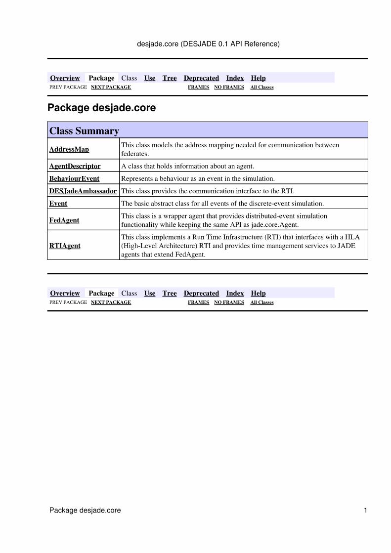
Overview Package Class Use Tree Deprecated Index Help PREV PACKAGE NEXT PACKAGE FRAMES NO FRAMES All Classes
Package desjade.core
Class Summary
AddressMap This class models the address mapping needed for communication betweenfederates.
AgentDescriptor A class that holds information about an agent.
BehaviourEvent Represents a behaviour as an event in the simulation.
DESJadeAmbassador This class provides the communication interface to the RTI.
Event The basic abstract class for all events of the discrete-event simulation.
FedAgent This class is a wrapper agent that provides distributed-event simulationfunctionality while keeping the same API as jade.core.Agent.
RTIAgentThis class implements a Run Time Infrastructure (RTI) that interfaces with a HLA(High-Level Architecture) RTI and provides time management services to JADEagents that extend FedAgent.
Overview Package Class Use Tree Deprecated Index Help PREV PACKAGE NEXT PACKAGE FRAMES NO FRAMES All Classes
desjade.core (DESJADE 0.1 API Reference)
Package desjade.core 1
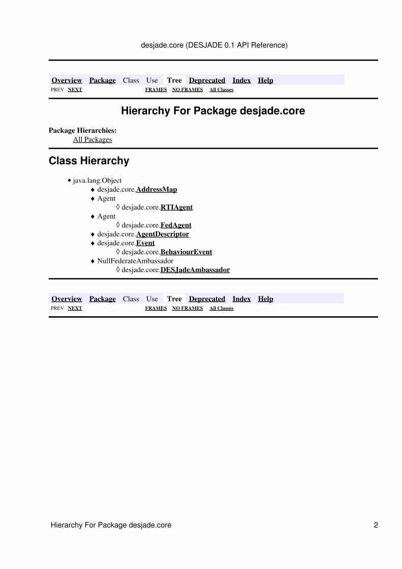
Overview Package Class Use Tree Deprecated Index Help PREV NEXT FRAMES NO FRAMES All Classes
Hierarchy For Package desjade.core
Package Hierarchies:All Packages
Class Hierarchy
java.lang.Objectdesjade.core.AddressMap♦ Agent
desjade.core.RTIAgent◊ ♦
Agentdesjade.core.FedAgent◊
♦
desjade.core.AgentDescriptor♦ desjade.core.Event
desjade.core.BehaviourEvent◊ ♦
NullFederateAmbassadordesjade.core.DESJadeAmbassador◊
♦
•
Overview Package Class Use Tree Deprecated Index Help PREV NEXT FRAMES NO FRAMES All Classes
desjade.core (DESJADE 0.1 API Reference)
Hierarchy For Package desjade.core 2

Overview Package Class Use Tree Deprecated Index HelpPREV CLASS NEXT CLASS FRAMES NO FRAMES All Classes
SUMMARY: NESTED | FIELD | CONSTR | METHOD DETAIL: FIELD | CONSTR | METHOD
desjade.coreClass FedAgent
java.lang.ObjectAgent
desjade.core.FedAgent
Direct Known Subclasses:DomainMasterAgent, FedPingAgent, RelayAgent
public abstract class FedAgentextends Agent
This class is a wrapper agent that provides distributed-event simulation functionality while keeping the sameAPI as jade.core.Agent.
Author:Fidelis Perkonigg
Field Summarystatic java.lang.String AGENT_SERVICE_SIGNATURE
The service type string this agent registers with the DF with.
Constructor SummaryFedAgent()
Method Summary void addBehaviour(SimBehaviour b)
It adds a new behaviour to the Agent.
protected double getLocalTime() Returns the current time of the simulation.
void removeBehaviour(SimBehaviour b) Method to remove a behaviour from the simulation.
protected void setup() Registers with the DF and starts the FedAgent kernel behaviour.
desjade.core (DESJADE 0.1 API Reference)
Class Hierarchy 3
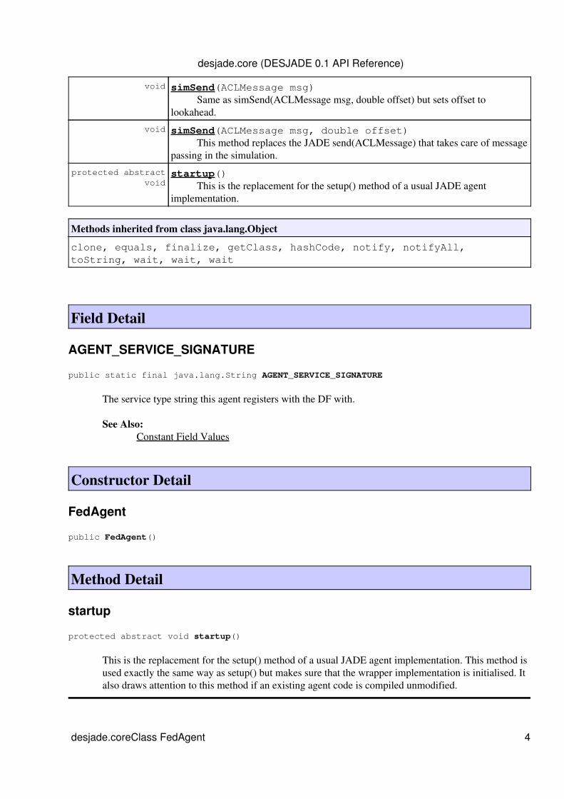
void simSend(ACLMessage msg) Same as simSend(ACLMessage msg, double offset) but sets offset tolookahead.
void simSend(ACLMessage msg, double offset) This method replaces the JADE send(ACLMessage) that takes care of messagepassing in the simulation.
protected abstract void
startup() This is the replacement for the setup() method of a usual JADE agentimplementation.
Methods inherited from class java.lang.Object
clone, equals, finalize, getClass, hashCode, notify, notifyAll,toString, wait, wait, wait
Field Detail
AGENT_SERVICE_SIGNATURE
public static final java.lang.String AGENT_SERVICE_SIGNATURE
The service type string this agent registers with the DF with.
See Also:Constant Field Values
Constructor Detail
FedAgent
public FedAgent()
Method Detail
startup
protected abstract void startup()
This is the replacement for the setup() method of a usual JADE agent implementation. This method isused exactly the same way as setup() but makes sure that the wrapper implementation is initialised. Italso draws attention to this method if an existing agent code is compiled unmodified.
desjade.core (DESJADE 0.1 API Reference)
desjade.coreClass FedAgent 4
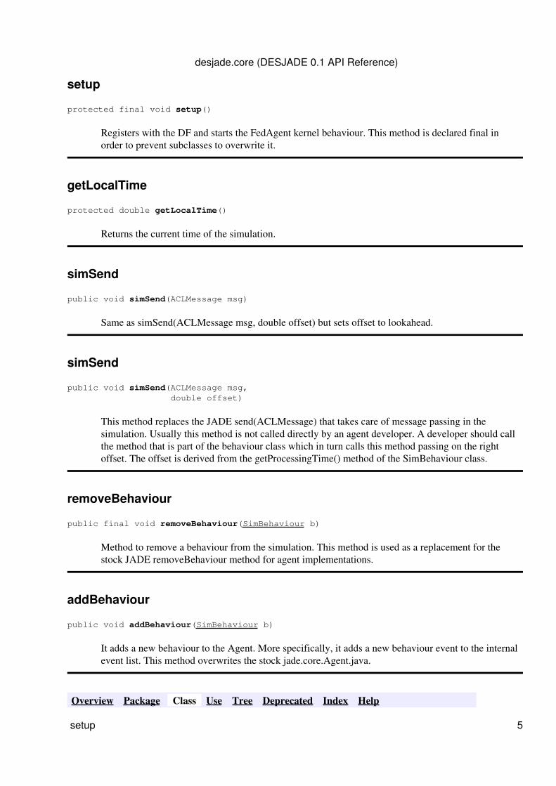
setup
protected final void setup()
Registers with the DF and starts the FedAgent kernel behaviour. This method is declared final inorder to prevent subclasses to overwrite it.
getLocalTime
protected double getLocalTime()
Returns the current time of the simulation.
simSend
public void simSend(ACLMessage msg)
Same as simSend(ACLMessage msg, double offset) but sets offset to lookahead.
simSend
public void simSend(ACLMessage msg, double offset)
This method replaces the JADE send(ACLMessage) that takes care of message passing in thesimulation. Usually this method is not called directly by an agent developer. A developer should callthe method that is part of the behaviour class which in turn calls this method passing on the rightoffset. The offset is derived from the getProcessingTime() method of the SimBehaviour class.
removeBehaviour
public final void removeBehaviour(SimBehaviour b)
Method to remove a behaviour from the simulation. This method is used as a replacement for thestock JADE removeBehaviour method for agent implementations.
addBehaviour
public void addBehaviour(SimBehaviour b)
It adds a new behaviour to the Agent. More specifically, it adds a new behaviour event to the internalevent list. This method overwrites the stock jade.core.Agent.java.
Overview Package Class Use Tree Deprecated Index Help
desjade.core (DESJADE 0.1 API Reference)
setup 5

PREV CLASS NEXT CLASS FRAMES NO FRAMES All ClassesSUMMARY: NESTED | FIELD | CONSTR | METHOD DETAIL: FIELD | CONSTR | METHOD
desjade.core (DESJADE 0.1 API Reference)
addBehaviour 6

Overview Package Class Use Tree Deprecated Index HelpPREV CLASS NEXT CLASS FRAMES NO FRAMES All Classes
SUMMARY: NESTED | FIELD | CONSTR | METHOD DETAIL: FIELD | CONSTR | METHOD
desjade.coreClass RTIAgent
java.lang.ObjectAgent
desjade.core.RTIAgent
public class RTIAgentextends Agent
This class implements a Run Time Infrastructure (RTI) that interfaces with a HLA (High-Level Architecture)RTI and provides time management services to JADE agents that extend FedAgent. At the moment it isassumed that only one RTIAgent exists. This agent registers with the DF so that the FedAgents can find andregister with it.
Author:Fidelis Perkonigg
Field Summarystatic java.lang.String AGENT_SERVICE_SIGNATURE
The service type string this agent registers with the DF with.
static java.lang.String CONVERSATION_ID_ORIG_MSG Message conversation ID to identify agent application messages
static java.lang.String CONVERSATION_ID_SIM Message conversation ID to identify internal conversationsbetween FedAgents and RTIAgent.
protected DESJadeAmbassador desjade_ambassador Handle to the DESJade ambassador class.
static java.lang.String ORIG_RECIPIENTS_LIST_SEPARATOR Defines the separator for the original recipient's list.
static java.lang.String PARAMETER_KEY_DATA_RECIPIENTS User defined paramter key for recipients of data messages.
static java.lang.String PARAMETER_KEY_DATA_TIMESTAMP User defined paramter key for time stamps of data messages.
static java.lang.String PARAMETER_KEY_LOOKAHEAD User defined paramter key for lookahead.
static java.lang.String
desjade.core (DESJADE 0.1 API Reference)
desjade.core Class RTIAgent 7
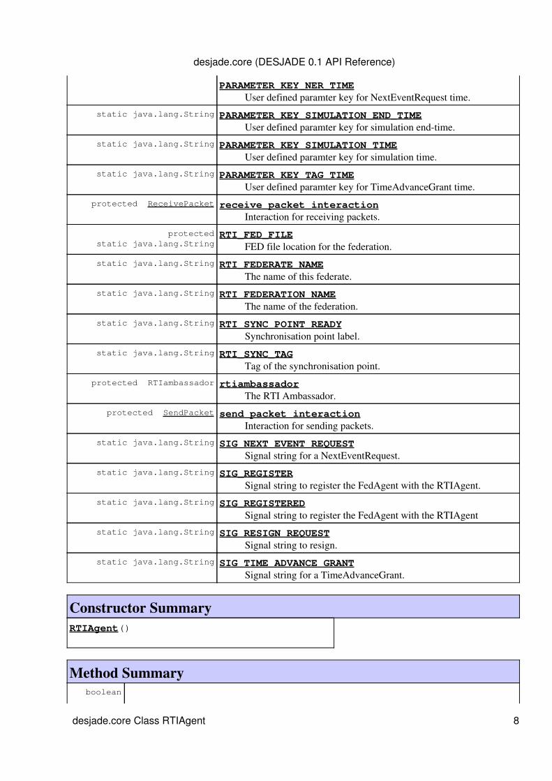
PARAMETER_KEY_NER_TIME User defined paramter key for NextEventRequest time.
static java.lang.String PARAMETER_KEY_SIMULATION_END_TIME User defined paramter key for simulation end-time.
static java.lang.String PARAMETER_KEY_SIMULATION_TIME User defined paramter key for simulation time.
static java.lang.String PARAMETER_KEY_TAG_TIME User defined paramter key for TimeAdvanceGrant time.
protected ReceivePacket receive_packet_interaction Interaction for receiving packets.
protectedstatic java.lang.String
RTI_FED_FILE FED file location for the federation.
static java.lang.String RTI_FEDERATE_NAME The name of this federate.
static java.lang.String RTI_FEDERATION_NAME The name of the federation.
static java.lang.String RTI_SYNC_POINT_READY Synchronisation point label.
static java.lang.String RTI_SYNC_TAG Tag of the synchronisation point.
protected RTIambassador rtiambassador The RTI Ambassador.
protected SendPacket send_packet_interaction Interaction for sending packets.
static java.lang.String SIG_NEXT_EVENT_REQUEST Signal string for a NextEventRequest.
static java.lang.String SIG_REGISTER Signal string to register the FedAgent with the RTIAgent.
static java.lang.String SIG_REGISTERED Signal string to register the FedAgent with the RTIAgent
static java.lang.String SIG_RESIGN_REQUEST Signal string to resign.
static java.lang.String SIG_TIME_ADVANCE_GRANT Signal string for a TimeAdvanceGrant.
Constructor SummaryRTIAgent()
Method Summary boolean
desjade.core (DESJADE 0.1 API Reference)
desjade.core Class RTIAgent 8
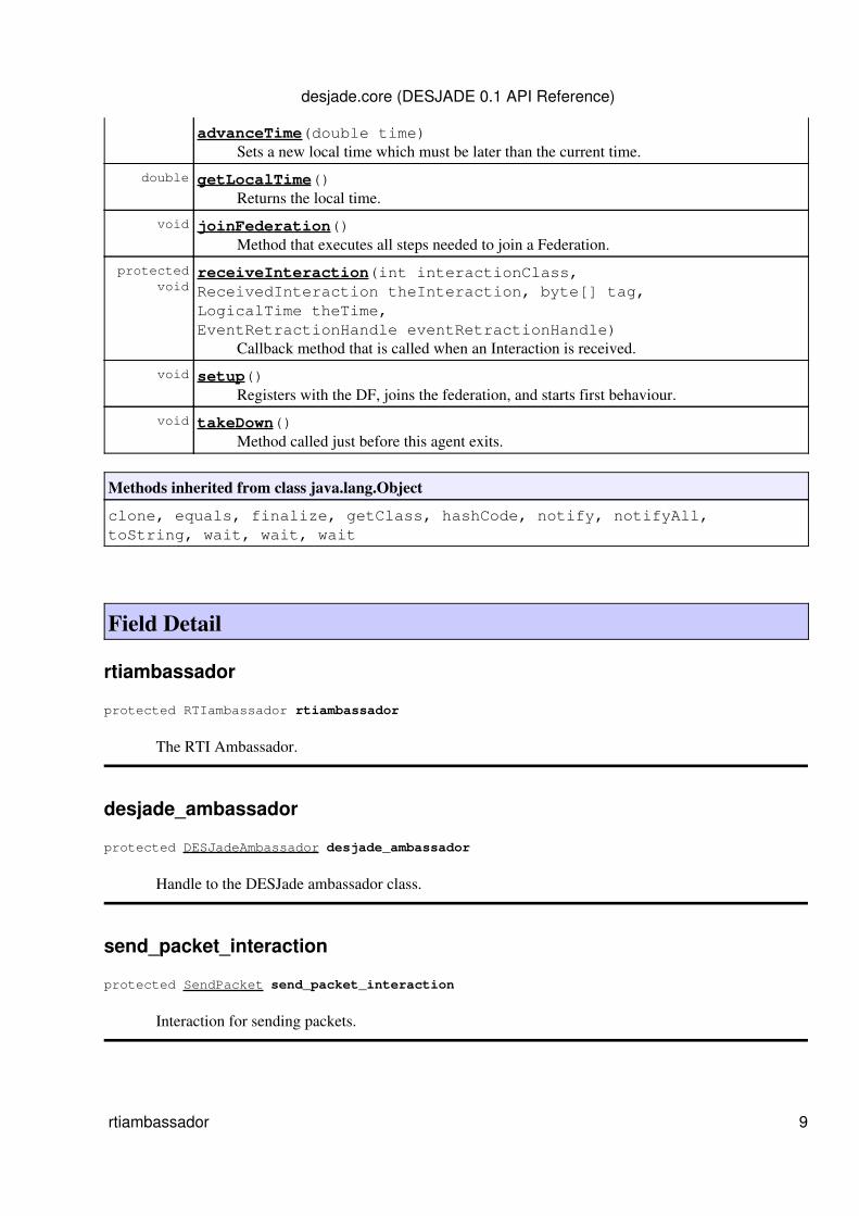
advanceTime(double time) Sets a new local time which must be later than the current time.
double getLocalTime() Returns the local time.
void joinFederation() Method that executes all steps needed to join a Federation.
protected void
receiveInteraction(int interactionClass,ReceivedInteraction theInteraction, byte[] tag,LogicalTime theTime,EventRetractionHandle eventRetractionHandle) Callback method that is called when an Interaction is received.
void setup() Registers with the DF, joins the federation, and starts first behaviour.
void takeDown() Method called just before this agent exits.
Methods inherited from class java.lang.Object
clone, equals, finalize, getClass, hashCode, notify, notifyAll,toString, wait, wait, wait
Field Detail
rtiambassador
protected RTIambassador rtiambassador
The RTI Ambassador.
desjade_ambassador
protected DESJadeAmbassador desjade_ambassador
Handle to the DESJade ambassador class.
send_packet_interaction
protected SendPacket send_packet_interaction
Interaction for sending packets.
desjade.core (DESJADE 0.1 API Reference)
rtiambassador 9

receive_packet_interaction
protected ReceivePacket receive_packet_interaction
Interaction for receiving packets.
RTI_FED_FILE
protected static final java.lang.String RTI_FED_FILE
FED file location for the federation.
See Also:Constant Field Values
RTI_FEDERATE_NAME
public static final java.lang.String RTI_FEDERATE_NAME
The name of this federate.
See Also:Constant Field Values
RTI_FEDERATION_NAME
public static final java.lang.String RTI_FEDERATION_NAME
The name of the federation.
See Also:Constant Field Values
RTI_SYNC_POINT_READY
public static final java.lang.String RTI_SYNC_POINT_READY
Synchronisation point label.
See Also:Constant Field Values
desjade.core (DESJADE 0.1 API Reference)
receive_packet_interaction 10

RTI_SYNC_TAG
public static final java.lang.String RTI_SYNC_TAG
Tag of the synchronisation point.
See Also:Constant Field Values
AGENT_SERVICE_SIGNATURE
public static final java.lang.String AGENT_SERVICE_SIGNATURE
The service type string this agent registers with the DF with.
See Also:Constant Field Values
CONVERSATION_ID_SIM
public static final java.lang.String CONVERSATION_ID_SIM
Message conversation ID to identify internal conversations between FedAgents and RTIAgent.
See Also:Constant Field Values
CONVERSATION_ID_ORIG_MSG
public static final java.lang.String CONVERSATION_ID_ORIG_MSG
Message conversation ID to identify agent application messages
See Also:Constant Field Values
SIG_REGISTER
public static final java.lang.String SIG_REGISTER
Signal string to register the FedAgent with the RTIAgent.
See Also:Constant Field Values
desjade.core (DESJADE 0.1 API Reference)
RTI_SYNC_TAG 11
SIG_NEXT_EVENT_REQUEST
public static final java.lang.String SIG_NEXT_EVENT_REQUEST
Signal string for a NextEventRequest.
See Also:Constant Field Values
SIG_REGISTERED
public static final java.lang.String SIG_REGISTERED
Signal string to register the FedAgent with the RTIAgent
See Also:Constant Field Values
SIG_TIME_ADVANCE_GRANT
public static final java.lang.String SIG_TIME_ADVANCE_GRANT
Signal string for a TimeAdvanceGrant.
See Also:Constant Field Values
SIG_RESIGN_REQUEST
public static final java.lang.String SIG_RESIGN_REQUEST
Signal string to resign.
See Also:Constant Field Values
PARAMETER_KEY_SIMULATION_TIME
public static final java.lang.String PARAMETER_KEY_SIMULATION_TIME
User defined paramter key for simulation time.
See Also:Constant Field Values
desjade.core (DESJADE 0.1 API Reference)
SIG_NEXT_EVENT_REQUEST 12

PARAMETER_KEY_SIMULATION_END_TIME
public static final java.lang.String PARAMETER_KEY_SIMULATION_END_TIME
User defined paramter key for simulation end-time.
See Also:Constant Field Values
PARAMETER_KEY_LOOKAHEAD
public static final java.lang.String PARAMETER_KEY_LOOKAHEAD
User defined paramter key for lookahead.
See Also:Constant Field Values
PARAMETER_KEY_NER_TIME
public static final java.lang.String PARAMETER_KEY_NER_TIME
User defined paramter key for NextEventRequest time.
See Also:Constant Field Values
PARAMETER_KEY_TAG_TIME
public static final java.lang.String PARAMETER_KEY_TAG_TIME
User defined paramter key for TimeAdvanceGrant time.
See Also:Constant Field Values
PARAMETER_KEY_DATA_RECIPIENTS
public static final java.lang.String PARAMETER_KEY_DATA_RECIPIENTS
User defined paramter key for recipients of data messages.
See Also:Constant Field Values
desjade.core (DESJADE 0.1 API Reference)
PARAMETER_KEY_SIMULATION_END_TIME 13

PARAMETER_KEY_DATA_TIMESTAMP
public static final java.lang.String PARAMETER_KEY_DATA_TIMESTAMP
User defined paramter key for time stamps of data messages.
See Also:Constant Field Values
ORIG_RECIPIENTS_LIST_SEPARATOR
public static final java.lang.String ORIG_RECIPIENTS_LIST_SEPARATOR
Defines the separator for the original recipient's list.
See Also:Constant Field Values
Constructor Detail
RTIAgent
public RTIAgent()
Method Detail
setup
public void setup()
Registers with the DF, joins the federation, and starts first behaviour.
takeDown
public void takeDown()
Method called just before this agent exits. For example it resigns from the federation and notifies theDF.
joinFederation
public void joinFederation() throws RTIexception
desjade.core (DESJADE 0.1 API Reference)
PARAMETER_KEY_DATA_TIMESTAMP 14

Method that executes all steps needed to join a Federation. It tries to create a new Federation if itdoesn't exist, loads the FED, joins the Federation, enables time management, publishes and subscribesto content, and registers a synchronisation point.Throws:
RTIexception
receiveInteraction
protected void receiveInteraction(int interactionClass, ReceivedInteraction theInteraction, byte[] tag, LogicalTime theTime, EventRetractionHandle eventRetractionHandle)
Callback method that is called when an Interaction is received.
advanceTime
public boolean advanceTime(double time)
Sets a new local time which must be later than the current time.
getLocalTime
public double getLocalTime()
Returns the local time.
Overview Package Class Use Tree Deprecated Index HelpPREV CLASS NEXT CLASS FRAMES NO FRAMES All Classes
SUMMARY: NESTED | FIELD | CONSTR | METHOD DETAIL: FIELD | CONSTR | METHOD
desjade.core (DESJADE 0.1 API Reference)
joinFederation 15
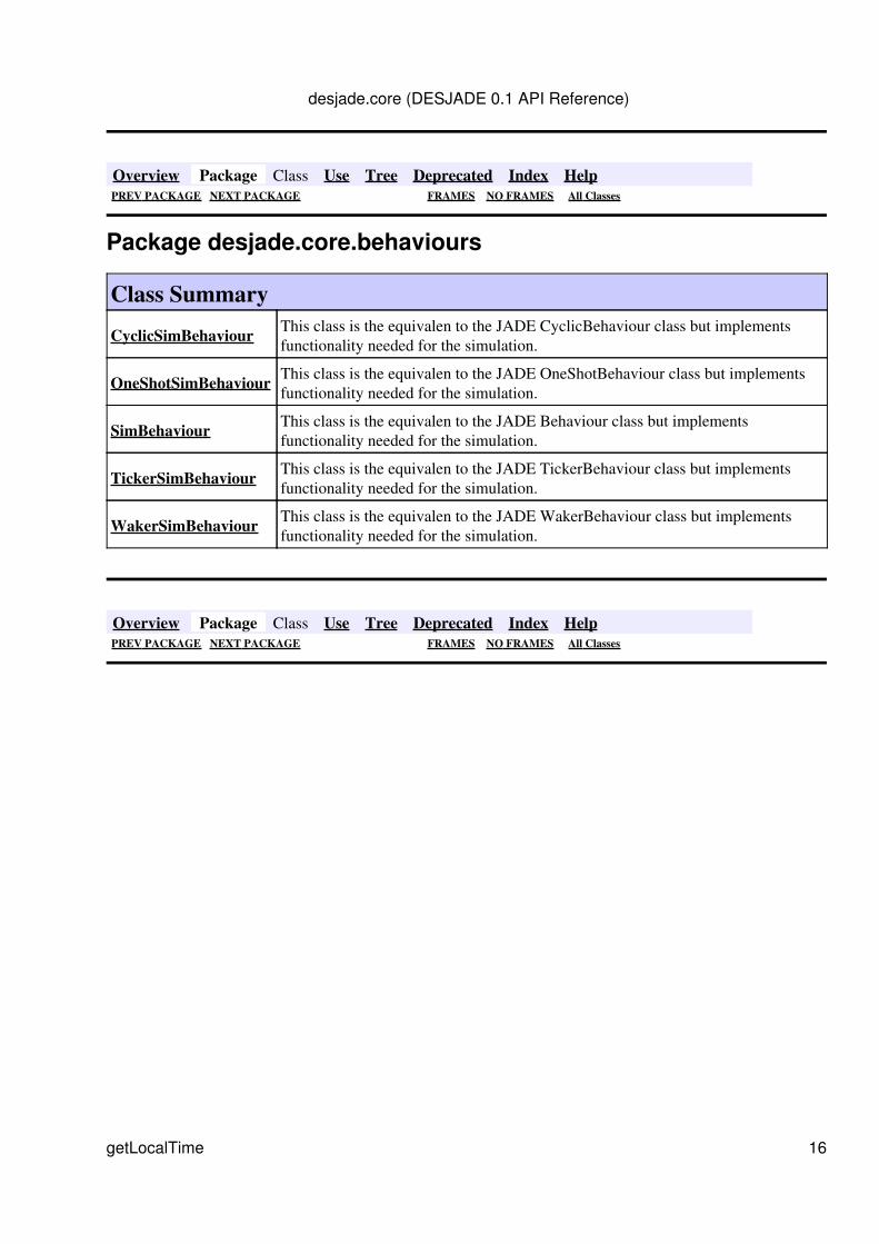
Overview Package Class Use Tree Deprecated Index HelpPREV PACKAGE NEXT PACKAGE FRAMES NO FRAMES All Classes
Package desjade.core.behaviours
Class Summary
CyclicSimBehaviour This class is the equivalen to the JADE CyclicBehaviour class but implementsfunctionality needed for the simulation.
OneShotSimBehaviour This class is the equivalen to the JADE OneShotBehaviour class but implementsfunctionality needed for the simulation.
SimBehaviour This class is the equivalen to the JADE Behaviour class but implementsfunctionality needed for the simulation.
TickerSimBehaviour This class is the equivalen to the JADE TickerBehaviour class but implementsfunctionality needed for the simulation.
WakerSimBehaviour This class is the equivalen to the JADE WakerBehaviour class but implementsfunctionality needed for the simulation.
Overview Package Class Use Tree Deprecated Index HelpPREV PACKAGE NEXT PACKAGE FRAMES NO FRAMES All Classes
desjade.core (DESJADE 0.1 API Reference)
getLocalTime 16
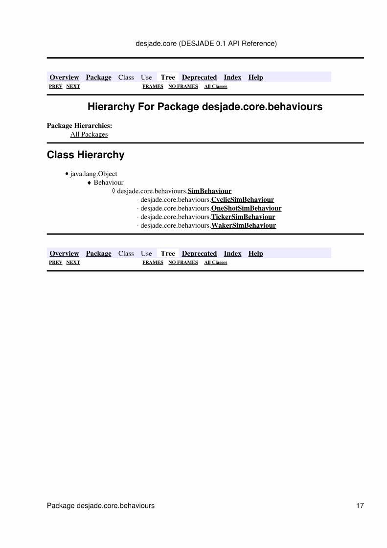
Overview Package Class Use Tree Deprecated Index HelpPREV NEXT FRAMES NO FRAMES All Classes
Hierarchy For Package desjade.core.behaviours
Package Hierarchies:All Packages
Class Hierarchy
java.lang.ObjectBehaviour
desjade.core.behaviours.SimBehaviourdesjade.core.behaviours.CyclicSimBehaviour⋅ desjade.core.behaviours.OneShotSimBehaviour⋅ desjade.core.behaviours.TickerSimBehaviour⋅ desjade.core.behaviours.WakerSimBehaviour⋅
◊ ♦
•
Overview Package Class Use Tree Deprecated Index HelpPREV NEXT FRAMES NO FRAMES All Classes
desjade.core (DESJADE 0.1 API Reference)
Package desjade.core.behaviours 17
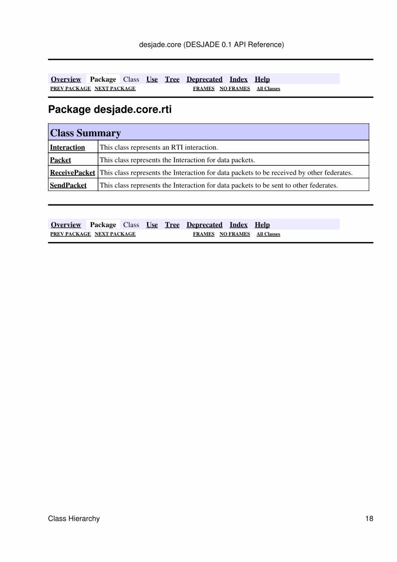
Overview Package Class Use Tree Deprecated Index HelpPREV PACKAGE NEXT PACKAGE FRAMES NO FRAMES All Classes
Package desjade.core.rti
Class SummaryInteraction This class represents an RTI interaction.
Packet This class represents the Interaction for data packets.
ReceivePacket This class represents the Interaction for data packets to be received by other federates.
SendPacket This class represents the Interaction for data packets to be sent to other federates.
Overview Package Class Use Tree Deprecated Index HelpPREV PACKAGE NEXT PACKAGE FRAMES NO FRAMES All Classes
desjade.core (DESJADE 0.1 API Reference)
Class Hierarchy 18
Overview Package Class Use Tree Deprecated Index HelpPREV NEXT FRAMES NO FRAMES All Classes
Hierarchy For Package desjade.core.rti
Package Hierarchies:All Packages
Class Hierarchy
java.lang.Objectdesjade.core.rti.Interaction
desjade.core.rti.Packetdesjade.core.rti.ReceivePacket⋅ desjade.core.rti.SendPacket⋅
◊ ♦
•
Overview Package Class Use Tree Deprecated Index HelpPREV NEXT FRAMES NO FRAMES All Classes
desjade.core (DESJADE 0.1 API Reference)
Package desjade.core.rti 19

Overview Package Class Use Tree Deprecated Index HelpPREV CLASS NEXT CLASS FRAMES NO FRAMES All Classes
SUMMARY: NESTED | FIELD | CONSTR | METHOD DETAIL: FIELD | CONSTR | METHOD
desjade.core.rtiClass Packet
java.lang.Objectdesjade.core.rti.Interaction
desjade.core.rti.Packet
Direct Known Subclasses:ReceivePacket, SendPacket
public class Packetextends Interaction
This class represents the Interaction for data packets.
Field Summaryprotected static java.lang.String dst_addr
protected int dst_addr_handle
protected int dst_addr_value
protected static java.lang.String message_id
protected int message_id_handle
protected long message_id_value
protected static java.lang.String payload_size
protected int payload_size_handle
protected int payload_size_value
protected static java.lang.String src_addr
desjade.core (DESJADE 0.1 API Reference)
Class Hierarchy 20
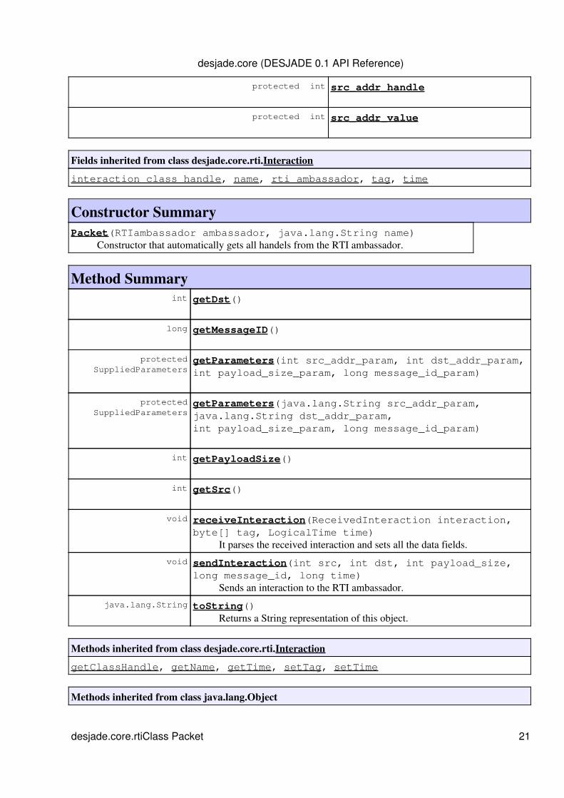
protected int src_addr_handle
protected int src_addr_value
Fields inherited from class desjade.core.rti.Interaction
interaction_class_handle, name, rti_ambassador, tag, time
Constructor SummaryPacket(RTIambassador ambassador, java.lang.String name) Constructor that automatically gets all handels from the RTI ambassador.
Method Summary int getDst()
long getMessageID()
protected SuppliedParameters
getParameters(int src_addr_param, int dst_addr_param,int payload_size_param, long message_id_param)
protected SuppliedParameters
getParameters(java.lang.String src_addr_param,java.lang.String dst_addr_param,int payload_size_param, long message_id_param)
int getPayloadSize()
int getSrc()
void receiveInteraction(ReceivedInteraction interaction,byte[] tag, LogicalTime time) It parses the received interaction and sets all the data fields.
void sendInteraction(int src, int dst, int payload_size,long message_id, long time) Sends an interaction to the RTI ambassador.
java.lang.String toString() Returns a String representation of this object.
Methods inherited from class desjade.core.rti.Interaction
getClassHandle, getName, getTime, setTag, setTime
Methods inherited from class java.lang.Object
desjade.core (DESJADE 0.1 API Reference)
desjade.core.rtiClass Packet 21
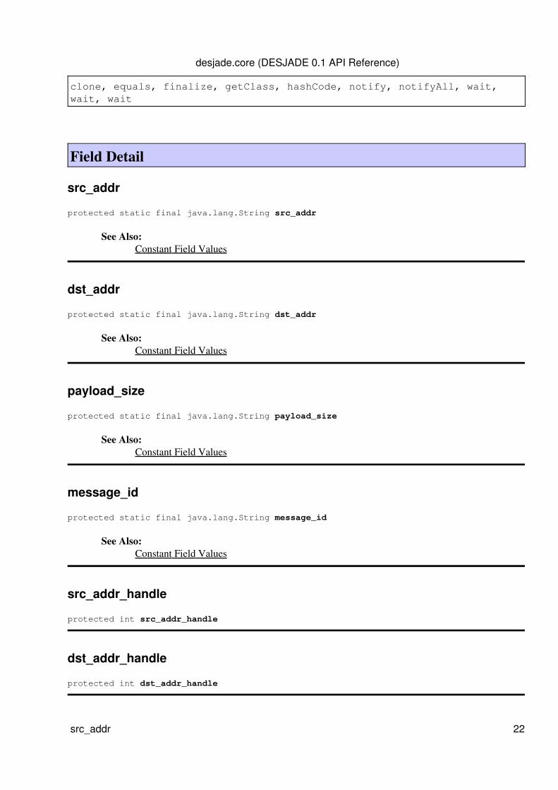
clone, equals, finalize, getClass, hashCode, notify, notifyAll, wait,wait, wait
Field Detail
src_addr
protected static final java.lang.String src_addr
See Also:Constant Field Values
dst_addr
protected static final java.lang.String dst_addr
See Also:Constant Field Values
payload_size
protected static final java.lang.String payload_size
See Also:Constant Field Values
message_id
protected static final java.lang.String message_id
See Also:Constant Field Values
src_addr_handle
protected int src_addr_handle
dst_addr_handle
protected int dst_addr_handle
desjade.core (DESJADE 0.1 API Reference)
src_addr 22
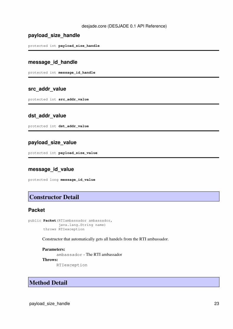
payload_size_handle
protected int payload_size_handle
message_id_handle
protected int message_id_handle
src_addr_value
protected int src_addr_value
dst_addr_value
protected int dst_addr_value
payload_size_value
protected int payload_size_value
message_id_value
protected long message_id_value
Constructor Detail
Packet
public Packet(RTIambassador ambassador, java.lang.String name) throws RTIexception
Constructor that automatically gets all handels from the RTI ambassador.
Parameters:ambassador - The RTI ambassador
Throws:RTIexception
Method Detail
desjade.core (DESJADE 0.1 API Reference)
payload_size_handle 23

sendInteraction
public void sendInteraction(int src, int dst, int payload_size, long message_id, long time) throws RTIexception
Sends an interaction to the RTI ambassador.Parameters:
src - The source address of the packetdst - The destination address of the packetpayload_size - The size of the packetmessage_id - The unique message IDtime - The simulation time
Throws:RTIexception
receiveInteraction
public void receiveInteraction(ReceivedInteraction interaction, byte[] tag, LogicalTime time)
It parses the received interaction and sets all the data fields.
getSrc
public int getSrc()
getDst
public int getDst()
getPayloadSize
public int getPayloadSize()
getMessageID
public long getMessageID()
desjade.core (DESJADE 0.1 API Reference)
sendInteraction 24
getParameters
protected SuppliedParameters getParameters(int src_addr_param, int dst_addr_param, int payload_size_param, long message_id_param) throws RTIexception
Throws:RTIexception
getParameters
protected SuppliedParameters getParameters(java.lang.String src_addr_param, java.lang.String dst_addr_param, int payload_size_param, long message_id_param) throws RTIexception
Throws:RTIexception
toString
public java.lang.String toString()
Returns a String representation of this object.Overrides:
toString in class Interaction
Overview Package Class Use Tree Deprecated Index HelpPREV CLASS NEXT CLASS FRAMES NO FRAMES All Classes
SUMMARY: NESTED | FIELD | CONSTR | METHOD DETAIL: FIELD | CONSTR | METHOD
desjade.core (DESJADE 0.1 API Reference)
getParameters 25