a mathematical formulation of inductance for multipole field … · 2018-06-17 · a mathematical...
TRANSCRIPT

A Mathematical Formulation ofInductance for Multipole FieldElectromagnetic Launcher
K.Sri Chandan, P. Mallikarjuna Rao,Research Scholar, Professor
Department of Electrical Engineering Andhra University,Visakhapatnam, India
[email protected],[email protected]
April 30, 2018
Abstract
Calculation of inductance is the key point for electricalpropulsion,as the performance parametersdepend on induc-tance value.In this paper, an inductanceformulais derivedbased on the flux distribution to develop the parametricmagnetic network model for Multipole Field Electromag-netic Launcher (MFEML).To account the magnetic field ef-fect in the launcher, multiple flux paths are considered toestimate the inductance profile.The theoreticalanalysis andnumerical simulations are performed and validated usingFinite Element Analysis.
Key Words:Multipole field, Flux distribution, Mag-netic Equivalent circuit, FEA.
1 Introduction
The intensifying demand for the linear motion of various automaticand robotic applications, electromagnetic launchers are becomingmore and more desirable. Multipole Electromagnetic Launchershas the potential of developing huge thrust force, large driven mass,
1
International Journal of Pure and Applied MathematicsVolume 118 No. 24 2018ISSN: 1314-3395 (on-line version)url: http://www.acadpubl.eu/hub/Special Issue http://www.acadpubl.eu/hub/

super velocity launch and steady maglev compared to conventionalelectrical launchers [1]-[3].In [4], it is indicated that the projec-tile is accelerated with spinning motion about its axis which couldkeep the projectile fly stability.The present research of MultipoleField Electromagnetic Launcher (MFEML)is mainly concentratingon theoretical analysis and experimental verification. For exam-ple, Zhu et al. [1]-[3] proposed the concepts of normal and twistyMFEML; Luo et al. [7] analyzed different connection patternsof MFEML and experimentally tested a single-stage launcher.Theabove research demonstrated the characteristicsof MFEML withan assumption that the basic principles of eddy-current catapultand multipole field induction acceleration are identical. And theLorentz force is been calculated by neglecting the leakage fluxes.However, previous studies excluded the leakage fluxes and insteadcreated an identical equivalent circuit for both the coils for thecalculation of Lorentz force.
In this paper, a flux concentrated Multipole Field Electromag-netic Launcher is introduced. As theinductance varies according tothe permeance waveform, it is necessary to analyze the relative per-meance before calculating the inductance.Hence a new methodologyis proposed to calculate permeance and further the inductance ofthe accelerating coils based on the position of the projecting object.The parameters are validated with Finite Element Analysis (FEA).
2 MAGENTIC NETWORKMODEL OF
MFEML
Fig.1, (a) shows the basic structure of a Single stage MultipoleField Electromagnetic Launcher and (b) shows the catapult coiland induction coil of the MFEML
2
International Journal of Pure and Applied Mathematics Special Issue

Fig. 1. (a) Basic Structure of Single stage MFEML
Fig. 1. (b) Catapult Coil and Induction Coil of MFEML
The working principle and the basic characteristics are elabo-rated in [1]-[3], in brief the catapult coil will give the initial pushto the object and the induction coils will guide the object to movealong the axis with high thrust. The catapult coil conductor isconsidered as cylindrical shape and it is kept in spiral arrangement.The induction coils and catapult coil are energized from a capacitorbank.
Fig. 2, (a) and (b) represents the flux flow diagram in a singlecoil of MFEMLwhen object is inside and outside the coil respec-tively.
3
International Journal of Pure and Applied Mathematics Special Issue

Fig. 2. (a) Flux lines in single coil of MFEML when object inside
Fig. 2. (b) Flux lines in single coil of MFEML when object outside
The flux paths are equiflux lines (i.e., equal amount of flux linesare represented by each flux path). The flux distribution is sym-metric with respect to the center line of the excited induction coil.The flux path 1 is assumed to have aflux of1 in the induction coil.It crosses the air gap, splits evenly in the object, and then recrossesthe air gap to the other side of the coil. The reluctances of theinduction coil, air gap, and objectfor the flux path are denoted asRc, Rg and Rp respectively. The magnetic circuit for a single coilis shown in Fig. 3.
Fig. 3. The Magnetic Network Model of MFEML
In this model, different flux paths around the poles are consideredto find the magnetic impedance of the magnetic equivalent model.Magnetic impedance is derived in terms of flux measured at themagnetic equivalent of the electrical terminals and the (MMF) re-luctance between them. The magnetic parameters need more care-ful definitions as the magnetic flux flow in more regions with differ-ent areas. So the general objective in this section is to derive thepermeances of each flux region, to find out the lumped equivalentinductance offered by the coils in the equivalent magnetic model.
4
International Journal of Pure and Applied Mathematics Special Issue

This equivalent inductance is further used to evaluate/attain theforce offered by the coils on the projecting body
The expressions for reluctance of the induction coil, air gapand object for the flux pathsare derived and the expressions arepresented in this section.
The Reluctance of Flux path 1Reluctance in induction coil
Rc1 =5lc
µ0µrwc(c − t)(1)
Reluctance in Air-gap
Rg1 =40lg
µ0wp(4hc + 5lp − 9t)(2)
Reluctance in Moving Object
Rp1 =π
4µ0µrphmwp
(
√l2p + h2m2lp
− 3
√(3lp+t
4)2 + (2hm
3)2
(3lp + t))×
√(7lp + t
8)2 + (
5hm6
)2 (3)
Reluctance in air gap to reach other side of the coil
Rog1 =4π(7hm + 6lg + 12lc)
3µ0wphm(4)
The Reluctance of Flux path 2Reluctance in induction coil
Rc2 =5lc
µ0µrwc(c − t)(5)
Reluctance in Air-gap
Rg2 =40lg
µ0wp(4hc + 5lp − 9t)(6)
Reluctance in Projecting Object
Rp2 =3π
4µ0µrphmwp
(
√(3lp+t
4)2 + (2hm
3)2
(3lp + t)−
√( lp+t
2)2 + (hm
3)2
(lp + t))×
5
International Journal of Pure and Applied Mathematics Special Issue

√(5lp + 3t
8)2 + (
hm8
)2 (7)
Reluctance in air gap to reach other side of the coil
Rog2 =2π(hm + 3lg + 6lc)
µ0wphm(8)
Where ,lc is length of the coil in meterslg is length of the air gap in metershc is height of the coil in meterslp is length of the projecting object in metershp is height of the projecting object in metershm is height of the metallic sheath in projecting object in meterswc is width of the coil in meterswp is width of the coil in meterst is thickness of the coil winding in metersµ0 is permeability of the airµrpis relative permeability of the projecting objectn is number of turnsIn a similar way,the reluctances of all the flux paths are been
derived and the equivalent magnetic circuit is developed as shownin Fig. 4
Fig. 4. The Magnetic Equivalent Circuit of MFEML
The complete inductance offered by the induction coil based onthe position of the object is found using
L =N2
Rtotal
(9)
6
International Journal of Pure and Applied Mathematics Special Issue
The force generated on the projectile is derived from the electro-mechanical energy conversion principles as,
F =1
2i2dL
dx(10)
The same methodology is followed for different position of theobject i.e., when the object totally outside, just entering and whileleaving the induction coil to estimate the inductance and force pro-file.
3 Inductance Calculation of catapult coil
The induction coils cannot provide the initial thrust because theforce generated by the induction coil is three dimensional [3]. Due towhich the object cannot move smoothly in the axis of the barrel. Toovercome this problem, catapult coil is used in the MPEML, whichprovide the initial thrust such that the object is given the directionin which way it has to propel. In this section, the inductance offeredby the catapult coil is presented. The catapult coil considered inthis work is a cylindrical cooper wire in a spiral arrangement whichis excited by a capacitor bank.
The inductance of the catapult coil is expressed as
Lc =N2A2
30A− 11Di
(11)
A = Di +Nc(w + s)
2(12)
WhereA= Area of the Spiral CoilDi= Inner Diameter of catapult coils= Distance between the coil windingw=Wire diameter of catapult coilNc= Number of turns catapult coilDo=Outer Diameter catapult coilThe overall electrical equivalent circuit of MFEML is presented
in Fig. 5.
7
International Journal of Pure and Applied Mathematics Special Issue

Fig. 5. Overall Electrical Equivalent circuit of MFEML
4 VALIDATION OF PROPOSED
MEHTOD BY COMPARING INDUC-
TANCES
The inductance profile of a single induction coil in MFEML is shownin Fig.6. It is observed that the maximum and minimum inductanceof the induction coil when the projecting object is completely insideis 30.2 mH and 23 mH respectively.
Fig. 6. Inductance Profile of a Single Coil of MFEML
To validate the inductance profile, Finite ElementAnalysis isim-plemented andflux distributions in the MFEML are plotted. Theflux density and flux intensity plots are shown in Fig. 7, 8& 9.
8
International Journal of Pure and Applied Mathematics Special Issue

Fig. 7. Flux density profile of MFEML
Fig. 8. Top view of Flux density profile in MFEML
Fig. 9. Flux intensity profile in MFEML
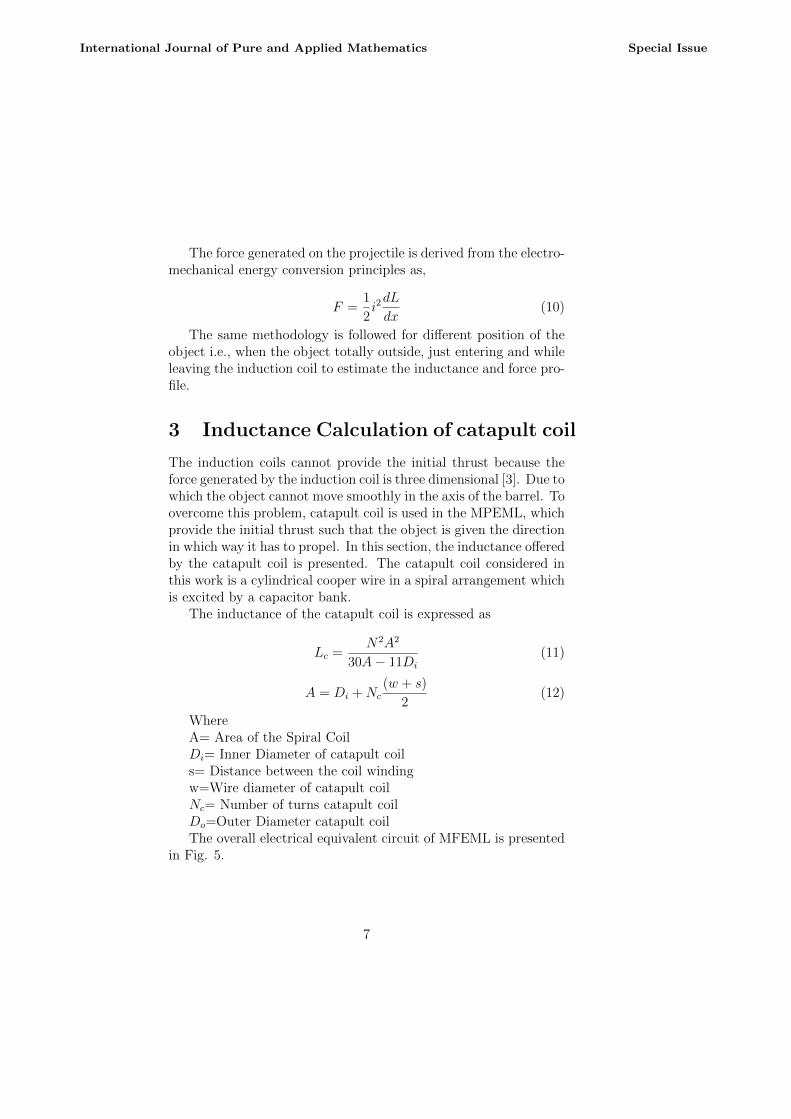
From the finite element analysis, the maximum inductance valueattained is 33 mH and the minimum inductance value observed is24 mH. And the comparison plot between the proposed method andFEA are shown in Fig. 10.
9
International Journal of Pure and Applied Mathematics Special Issue
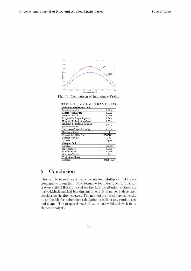
Fig. 10. Comparison of Inductance Profile
TABLE 1. SYSTEM PARAMETERS
5 Conclusion
This article introduces a flux concentrated Multipole Field Elec-tromagnetic Launcher. New formulae for inductance of anaccel-eration coilof MFEML based on the flux distribution method arederived.Mathematical basedmagnetic circuit is model is developedconsidering the flux leakages. The method proposed here can easilybe applicable for inductance calculation of coils of any random sizeand shape. The proposed method values are validated with finiteelement analysis.
10
International Journal of Pure and Applied Mathematics Special Issue
References
[1] Y. Zhu, Y. Wang, Z. Yan, L. Dong, X. Xie, and H. Li, Mul-tipolefield electromagnetic launcher, IEEE Trans. Magn., vol.46, no. 1, pp 2622- 2627, Jun. 2010
[2] Antonino Musolino, Rocco Rizzo, and Ernesto Tripodi, Trav-elling Wave Multipole Field Electromagnetic Launcher: AnSOVP Analytical Model, IEEE Transactions On Plasma Sci-ence, Vol. 41, No. 5, May 2013
[3] Xinpeng Xue, Tao Shu, Zhiyong Yang, and Gang Feng,Toroidal Field Electromagnetic Launcher, IEEE Transactionson Plasma Science, Vol. 44, No. 10, October 2016.
[4] Zhu Yingwei, Wang Yu, Chen Weirong, Yan Zhongming, andLi Haitao, Analysis and Evaluation of Three-Stage Twisty Oc-tapole Field Electromagnetic Launcher, IEEE Transactions OnPlasma Science, Vol. 40, No. 5, May 2012
[5] Frederick W. Grover, Inductance Calculation, Dover Publica-tion, 2009.
[6] Xinpeng Xue, Tao Shu, Zhiyong Yang, and Gang Feng, A NewElectromagnetic Launcher by Sextupole Rails: Electromag-netic Propulsion and Shielding Numerical Validation, IEEETransactions On Plasma Science, Vol. 45, No. 9, September2017.
[7] Wenbo Luo, Yu Wang, Zhixing Gui, Zhongming Yan, andWeirong Chen, Connection Pattern Research and Experimen-tal Realization of Single Stage Multipole Field ElectromagneticLauncher, IEEE Transactions On Plasma Science, Vol. 41, No.11, November 2013
[8] Ahmadali Khatibzadeh, M.R. Besmi, Improve Dimensionof Projectile For Increasing Efficiency of ElectromagneticLauncher, 4th Power Electronics, Drive Systems & Technolo-gies Conference (PEDSTC2013), Feb 13-14,2013, Tehran, Iran.78-1-4673-4484-5/13 20I3 IEEE.
11
International Journal of Pure and Applied Mathematics Special Issue
[9] Zhongming Yan, Xiaofei Long, Falong Lu, Yu Wang, and Han-jun Liu, Study of Single-Stage Double-Armature MultipoleField Electromagnetic Launcher, IEEE transactions on plasmascience, vol. 45, no. 8, August 2017
[10] Rafael Mendes Duarte and Gordana Klaric Felic, Analysis ofthe Coupling Coefficient in Inductive Energy Transfer Systems,The University of Melbourne, Parkville, VIC 3010, Australia,Volume 2014 (2014), Article ID 951624, 6 page, 2014.
[11] Smythe, w., (1939), ”Static and Dynamic Electricity,”McGraw-Hill Book Co., Inc., New York, First edition (1939),316.
[12] C. D. Sijoy and Shashank Chaturvedi , Calculation of Accu-rate Resistance and Inductance for Complex Magnetic CoilsUsing the Finite-Difference Time-Domain Technique for Elec-tromagnetic, IEEE Transactions On Plasma Science, Vol. 36,No. 1, February 2008.
[13] Y. P. Su, Xun Liu and S. Y. Ron Hui,Mutual inductance Cal-culation of Movable Planar Coils on Parallel Surfaces,IEEETransactions On Power Electronics, Vol. 24, No. 4, April 2009.
[14] John T.Conway, Inductance Calculation for Non coaxial CoilsUsing Bessel Functions, IEEE Transactions on Magnetics,Vol.43, No.3, March 2007.
[15] Slobodan Babic and Cevdet Akyel,Improvement in calculationof the self and Mutual Inductance of Thin wall Solenoids andDisk Coils, IEEE Transactions on Magnetics, Vol.36, No.4,July 2000.
[16] Babic, S. I. and C. Akyel, New analytic-numerical solutionsfor the mutual inductance of two coaxial circular coils withrectangular cross section in air, IEEE Trans. Mag., Vol. 42,No. 6, 16611669, Jun. 2006
[17] K. Sri Chandan, P. Mallikarjuna Rao, Comprehensive Analy-sis of OctapoleElectromagnetic Launcher, International Jour-nal for Research in Applied Science & Engineering Technology(IJRASET), Volume 5 Issue 10, October 2017.
12
International Journal of Pure and Applied Mathematics Special Issue

[18] Sandhya Thotakura, Mallikarjuna Rao Pasumarthi, A NewMethod for Computation of Dynamic Inductance of TubularMotor, Journal of Electrical Engineering, November 2017.
BIOGRAPHY
K. Sri Chandan is currently a researchscholar in AndhraUniversity, AndhraPradesh, Visakhapatnam, India. (e-mail:[email protected]).
Dr. P. Mallikarjuna Rao is currently withAndhra Uni-versity, Visakhapatnam,Andhra Pradesh, India, where heis aprofessor of Electrical Engineering. Hisresearch in-terests include control systems, Design and analysisof specific purposeelectrical machines and their control.(email:[email protected]).
13
International Journal of Pure and Applied Mathematics Special Issue