a magnetic field cloak for charged particle beams · figure 1: concept of a magnetic eld cloak....
TRANSCRIPT
A Magnetic Field Cloak For Charged Particle Beams
K. G. Capobianco-Hogana,b, R. Cervantesa,d, A. Deshpandea,c, N. Feegea,∗,T. Krahulika,e, J. LaBountya,d, R. Sekelskya, A. Adhyatmana,
G. Arrowsmith-Krona, B. Coea,f, K. Dehmelta, T. K. Hemmicka, S. Jeffasa,T. LaByera, S. Mahmuda, A. Oliveiraa, A. Quadria, K. Sharmaa,
A. Tishelman-Charnya,g
aDepartment of Physics and Astronomy, Stony Brook University, Stony Brook, NY 11794,USA
bSuperconducting Magnet Division, Brookhaven National Laboratory, Upton, NY 11973,USA
cPhysics Department, Brookhaven National Laboratory, Upton, NY 11973, USAdDepartment of Physics, University of Washington, Seattle, WA 98195, USA
eDepartment of Physics, University of Virginia, Charlottesville, VA 22904, USAfCollider Accelerator Department, Brookhaven National Laboratory, Upton, NY 11973, USA
gPhysics Department, Northeastern University, Boston, MA 02115, USA
Abstract
Shielding charged particle beams from transverse magnetic fields is a commonchallenge for particle accelerators and experiments. We demonstrate that amagnetic field cloak is a viable solution. It allows for the use of dipole magnets inthe forward regions of experiments at an Electron Ion Collider (EIC) and otherfacilities without interfering with the incoming beams. The dipoles can improvethe momentum measurements of charged final state particles at angles close tothe beam line and therefore increase the physics reach of these experiments.In contrast to other magnetic shielding options (such as active coils), a cloakrequires no external powering. We discuss the design parameters, fabrication,and limitations of a magnetic field cloak and demonstrate that cylinders madefrom 45 layers of YBCO high-temperature superconductor, combined with aferromagnetic shell made from epoxy and stainless steel powder, shield morethan 99% of a transverse magnetic field of up to 0.45 T (95 % shielding at0.5 T) at liquid nitrogen temperature. The ferromagnetic shell reduces fielddistortions caused by the superconductor alone by 90% at 0.45 T.
Keywords: Electron Ion Collider, Interaction region, Magnetic field shielding,Magnetic field cloaking
Preprint submitted to Nuclear Instruments and Methods in Physics Research, Section A November 21, 2017
arX
iv:1
707.
0236
1v2
[ph
ysic
s.ac
c-ph
] 2
0 N
ov 2
017

+ =
Figure 1: Concept of a magnetic field cloak. From left to right: A superconducting cylinderpushes out magnetic field lines, a ferromagnetic cylinder pulls in magnetic field lines, and thecombination of both forms a cloak (given the correct thickness and magnetic permeability ofthe ferromagnet).
1. Introduction
Magnetic fields are routinely used to steer charged particle beams and toanalyze the momenta of charged particles produced in fixed-target and colliderexperiments. The field component transverse to the trajectory of a chargedparticle deflects it and, in the case of a polarized beam crossing a field gradi-ent, depolarizes it. Beams at particle collider facilities need adequate shieldingfrom fields that would cause disturbances. Established designs of magnetic fieldshields use cylinders made from low-temperature superconductors [1]. Magneticflux lines incident on a superconducting cylinder induce screening currents, andthe magnetic fields generated by these currents counteract the external field.As a result, the inside of the cylinder remains field-free, while the field on theoutside is distorted. This distortion can be corrected by adding a ferromag-netic shell around the superconductor. Unlike the superconductor, a ferromag-netic shell pulls in magnetic flux lines. The combination of superconductorand ferromagnet forms a magnetic field cloak (see Fig. 1). The ferromagnetof a superconductor-ferromagnet bilayer effectively contains all field distortionscaused by the superconductor if its magnetic permeability µr is tuned to
µr =R2
2 +R21
R22 −R2
1
, (1)
where R1 and R2 are the inner and outer radius of the ferromagnet (R1 is alsothe outer radius of the superconductor) [2]. Thus, a cloak can provide a field-freetunnel without disturbing the external field.
Magnetic field cloaks are topics of active research [3, 4]. We want to demon-strate that our design, which uses high-temperature superconductor (HTS)cylinders, is a viable solution to cloak charged particle beams at future parti-cle accelerator facilities such as the Electron Ion Collider (EIC). Such a facility
∗Corresponding authorEmail address: [email protected] (N. Feege)
2
would require a cloak that shields a magnetic field of at least 0.5 T over a lengthof 1 m. Section 2 briefly summarizes the basics of shielding magnetic fields withsuperconductors, Sec. 3 explains the fabrication of our superconductor shieldsand cloak prototypes, Sec. 4 describes our test setups, Sec. 5 presents the resultsof magnetic field shielding and cloaking measurements with our prototypes, andSec. 6 gives our conclusions.
2. Shielding magnetic fields with high temperature superconductors
The response of a type-II superconductor to magnetic fields is characterizedby two critical fields: Bc1 and Bc2. If a cylinder made from such a materialis exposed to a transverse magnetic field below Bc1, the flux lines are bentaround the cylinder. Above a certain threshold field, the field penetrating thesuperconductor has an approximately logarithmic time dependence [5]. BetweenBc1 and Bc2, flux vortices form and allow the field to partially seep through thesuperconductor. In this field range, stacking multiple layers of superconductorimproves the overall magnetic field shielding. Above Bc2, the superconductivityis destroyed and the field passes through the shield. The critical fields of asuperconductor become larger the lower the superconductor’s temperature fallsbelow its critical temperature.
High-temperature superconductors (HTS) are especially convenient becausethey can be cooled below their critical temperature with liquid nitrogen (ratherthan liquid helium), resulting in relatively modest cryogenic costs and fast pro-totyping. Although various experiments have characterized HTS shields [6, 7,8, 9, 10, 11], we are not aware of any substantial shielding past 10 mT withsuch materials, especially for transverse fields. Ref. [11] comes closest, but theauthors only shield approximately 60% of the field with an applied field of am-plitude 50 mT and frequency 10 Hz. If HTS can be demonstrated to shield fieldsabove 0.5 T, they can replace low temperature superconductor shields (such asNbTi sheets [12]).
3. Prototype construction
3.1. 1 m long / 2-layer and a 4.5 inch long / 4-layer HTS shield
We use 46 mm wide superconductor wire insert manufactured by Ameri-can Superconductor Inc (www.amsc.com) to fabricate superconducting cylinders.This width is an intermediate stage on their production line and, due to lowdemand, not currently supported as a product [13]. The insert is made from aYBCO ceramic with a critical temperature of about 90 K. The ceramic is de-posited on an oxide-buffered Ni-W alloy substrate and coated with silver. Thewidth and flexibility of this superconductor allow us to combine two strips to acylinder of up to approximately 1 inch diameter. The orientation of the stripsalong the cylinder axis facilitates the induction of supercurrents that generatea magnetic dipole field. Therefore, it is most effective for shielding transversemagnetic fields [14]. The maximum field that a cylinder can shield increases
3
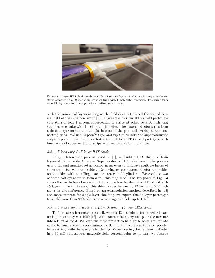
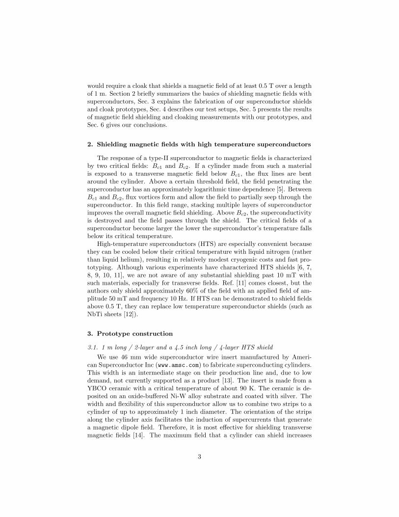
Figure 2: 2-layer HTS shield made from four 1 m long layers of 46 mm wide superconductorstrips attached to a 60 inch stainless steel tube with 1 inch outer diameter. The strips forma double layer around the top and the bottom of the tube.
with the number of layers as long as the field does not exceed the second crit-ical field of the superconductor [15]. Figure 2 shows our HTS shield prototypeconsisting of four 1 m long superconductor strips attached to a 60 inch longstainless steel tube with 1 inch outer diameter. The superconductor strips forma double layer on the top and the bottom of the pipe and overlap at the con-necting sides. We use Kapton R© tape and zip ties to hold the superconductorstrips in place. In addition, we test a 4.5 inch long HTS shield prototype withfour layers of superconductor strips attached to an aluminum tube.
3.2. 4.5 inch long / 45-layer HTS shield
Using a fabrication process based on [1], we build a HTS shield with 45layers of 46 mm wide American Superconductor HTS wire insert. The processuses a die-and-mandrel setup heated in an oven to laminate multiple layers ofsuperconductor wire and solder. Removing excess superconductor and solderon the sides with a milling machine creates half-cylinders. We combine twoof these half cylinders to form a full shielding tube. The left panel of Fig. 3shows the two halves of our 4.5 inch long, 1 inch outer diameter HTS shield with45 layers. The thickness of this shield varies between 0.22 inch and 0.26 inchalong its circumference. Based on an extrapolation method described in [15]and measurements for single layer shielding, we expect this 45-layer prototypeto shield more than 99% of a transverse magnetic field up to 0.5 T.
3.3. 4.5 inch long / 4-layer and 4.5 inch long / 45-layer HTS cloak
To fabricate a ferromagnetic shell, we mix 430 stainless steel powder (mag-netic permeability µ ≈ 1000 [16]) with commercial epoxy and pour the mixtureinto a tubular mold. We keep the mold upright to help air bubbles accumulateat the top and invert it every minute for 30 minutes to prevent the steel powderfrom setting while the epoxy is hardening. When placing the hardened cylinderin a 30 mT homogenous magnetic field perpendicular to its axis, we observe
4
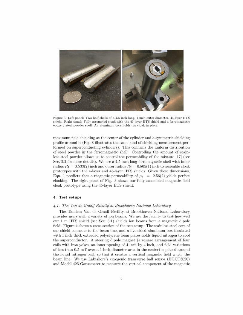
Figure 3: Left panel: Two half-shells of a 4.5 inch long, 1 inch outer diameter, 45-layer HTSshield. Right panel: Fully assembled cloak with the 45-layer HTS shield and a ferromagneticepoxy / steel powder shell. An aluminum core holds the cloak in place.
maximum field shielding at the center of the cylinder and a symmetric shieldingprofile around it (Fig. 8 illustrates the same kind of shielding measurement per-formed on superconducting cylinders). This confirms the uniform distributionof steel powder in the ferromagnetic shell. Controlling the amount of stain-less steel powder allows us to control the permeability of the mixture [17] (seeSec. 5.2 for more details). We use a 4.5 inch long ferromagnetic shell with innerradius R1 = 0.533(2) inch and outer radius R2 = 0.805(1) inch to assemble cloakprototypes with the 4-layer and 45-layer HTS shields. Given these dimensions,Eqn. 1 predicts that a magnetic permeability of µr = 2.56(2) yields perfectcloaking. The right panel of Fig. 3 shows our fully assembled magnetic fieldcloak prototype using the 45-layer HTS shield.
4. Test setups
4.1. The Van de Graaff Facility at Brookhaven National Laboratory
The Tandem Van de Graaff Facility at Brookhaven National Laboratoryprovides users with a variety of ion beams. We use the facility to test how wellour 1 m HTS shield (see Sec. 3.1) shields ion beams from a magnetic dipolefield. Figure 4 shows a cross section of the test setup. The stainless steel core ofour shield connects to the beam line, and a five-sided aluminum box insulatedwith 1 inch thick extruded polystyrene foam plates holds liquid nitrogen to coolthe superconductor. A steering dipole magnet (a square arrangement of fourcoils with iron yokes, an inner opening of 4 inch by 4 inch, and field variationsof less than 0.5 mT over a 1 inch diameter area in the center) is placed aroundthe liquid nitrogen bath so that it creates a vertical magnetic field w.r.t. thebeam line. We use Lakeshore’s cryogenic transverse hall sensor (HGCT3020)and Model 425 Gaussmeter to measure the vertical component of the magnetic
5
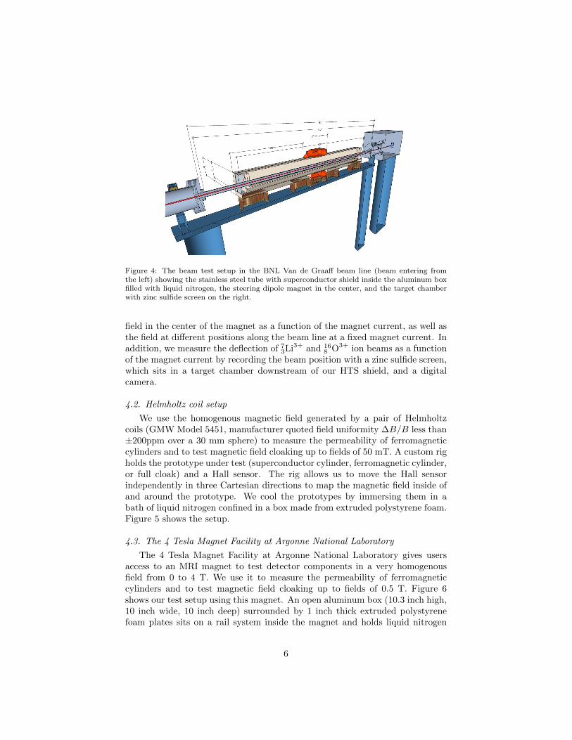
Figure 4: The beam test setup in the BNL Van de Graaff beam line (beam entering fromthe left) showing the stainless steel tube with superconductor shield inside the aluminum boxfilled with liquid nitrogen, the steering dipole magnet in the center, and the target chamberwith zinc sulfide screen on the right.
field in the center of the magnet as a function of the magnet current, as well asthe field at different positions along the beam line at a fixed magnet current. Inaddition, we measure the deflection of 7
3Li3+ and 168 O3+ ion beams as a function
of the magnet current by recording the beam position with a zinc sulfide screen,which sits in a target chamber downstream of our HTS shield, and a digitalcamera.
4.2. Helmholtz coil setup
We use the homogenous magnetic field generated by a pair of Helmholtzcoils (GMW Model 5451, manufacturer quoted field uniformity ∆B/B less than±200ppm over a 30 mm sphere) to measure the permeability of ferromagneticcylinders and to test magnetic field cloaking up to fields of 50 mT. A custom righolds the prototype under test (superconductor cylinder, ferromagnetic cylinder,or full cloak) and a Hall sensor. The rig allows us to move the Hall sensorindependently in three Cartesian directions to map the magnetic field inside ofand around the prototype. We cool the prototypes by immersing them in abath of liquid nitrogen confined in a box made from extruded polystyrene foam.Figure 5 shows the setup.
4.3. The 4 Tesla Magnet Facility at Argonne National Laboratory
The 4 Tesla Magnet Facility at Argonne National Laboratory gives usersaccess to an MRI magnet to test detector components in a very homogenousfield from 0 to 4 T. We use it to measure the permeability of ferromagneticcylinders and to test magnetic field cloaking up to fields of 0.5 T. Figure 6shows our test setup using this magnet. An open aluminum box (10.3 inch high,10 inch wide, 10 inch deep) surrounded by 1 inch thick extruded polystyrenefoam plates sits on a rail system inside the magnet and holds liquid nitrogen
6

Figure 5: The Helmholtz coil setup with our 80/20 rig. The rig holds our prototypes andallows us to move a Hall sensor in all three spatial directions inside and around the prototypeunder test.
for cooling. Our 45-layer HTS shield, a ferromagnet cylinder, and a full cloakcan be held inside this box by a mount fixed to its base. We use a translationalstage (three Cartesian degrees of freedom) on the rails to position a Hall sensorconnected to a long rod to measure the magnetic field inside our prototypes andto map the magnetic field around them.
5. Results
5.1. Magnetic field shielding
We use all three setups described in Sec.4 to test different aspects of shieldingmagnetic fields with our HTS shields. In the Van de Graaff setup, the 1 m long,2-layer HTS shield extends significantly past the magnet. Therefore, we expectonly minimal field leaking in through the ends of the shield. Figure 7 shows thevertical component BT of the magnetic field in this setup measured with a Hallsensor at different positions along the beam axis. The steering magnet is set toa nominal field of 30 mT. An offset of 0.1 mT is added to all measurements tomake negative values visible on the logarithmic scale. The figure compares mea-surements at room temperature and with liquid nitrogen cooling. This showsthat the 1 m long, 2-layer HTS tube shields most of the dipole field when it is inits superconducting state. We attribute the field distortions inside the shield tomechanical imperfections (which allow field to leak through the shield), as wellas artifacts caused by background fields trapped inside the superconductor dur-ing cool-down. In addition, the ferromagnetic substrate of the superconductorcauses field distortions both at room temperature and at cryogenic tempera-tures. Figure 8 shows the same type of measurement for the 4.5 inch, 4-layerHTS and 4.5 inch, 45-layer HTS shields placed inside the Helmholtz coils setup.The distortions inside these shields are smaller. However, a significant fraction
7
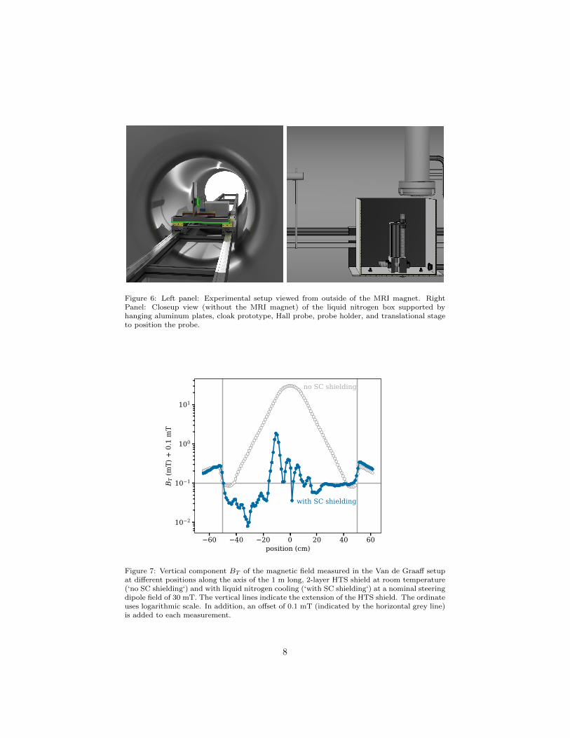
Figure 6: Left panel: Experimental setup viewed from outside of the MRI magnet. RightPanel: Closeup view (without the MRI magnet) of the liquid nitrogen box supported byhanging aluminum plates, cloak prototype, Hall probe, probe holder, and translational stageto position the probe.
Figure 7: Vertical component BT of the magnetic field measured in the Van de Graaff setupat different positions along the axis of the 1 m long, 2-layer HTS shield at room temperature(‘no SC shielding‘) and with liquid nitrogen cooling (‘with SC shielding‘) at a nominal steeringdipole field of 30 mT. The vertical lines indicate the extension of the HTS shield. The ordinateuses logarithmic scale. In addition, an offset of 0.1 mT (indicated by the horizontal grey line)is added to each measurement.
8

Figure 8: Magnetic field component BT measured at various positions along the axis of the4.5 inch long, 4-layer HTS and 4.5 inch long, 45-layer HTS shields in the Helmholtz coils setupat a nominal field of 40 mT. The vertical lines indicate the extension of the HTS shields. Theordinate uses logarithmic scale.
of the field leaks into the shields because the Helmholtz coils extend beyond theends of these shields. This effect is stronger for the 4-layer HTS shield becauseits inner diameter is larger than the inner diameter of the 45-layer shield. Figure9 shows the field measured with a Hall sensor in the center of the 2-layer, 1 mlong superconductor shield in the Van de Graaff setup as a function of time fornominal steering dipole fields of Ba = 11 mT and Ba = 45 mT. At the lowerdipole setting, the field inside this shield is stable, while at the higher dipolesetting it increases approximately logarithmically with time. As mentioned inSec. 2, such a time dependence above a certain threshold field is an expectedbehavior for HTS shields. Figure 10 shows the magnetic field shielding perfor-mance of the 1 m long, 2-layer HTS shield in the Van de Graaff setup. Thetop panel presents the deflection of a 8.14 MeV 7
3Li3+ beam as a function of thesteering dipole field Ba, both at room temperature (superconductor does notshield field) and at liquid nitrogen temperature (superconductor shields field).The superconducting shield reduces the beam deflection by about 94% (see [18]for a comparison of our 7
3Li3+ and 168 O3+ results). The bottom panel shows the
field measured with a Hall sensor in the center of the shield as a function ofsteering dipole fields. The open markers indicate field measurements that showthe previously mentioned increase over time, i.e. measurements for which themean reading in the last quarter is more than two standard deviations higherthan the mean reading in the first quarter of a ten minute measurement. Fig-ure 11 shows the shielding performance of our 45-layer HTS shield prototype
9
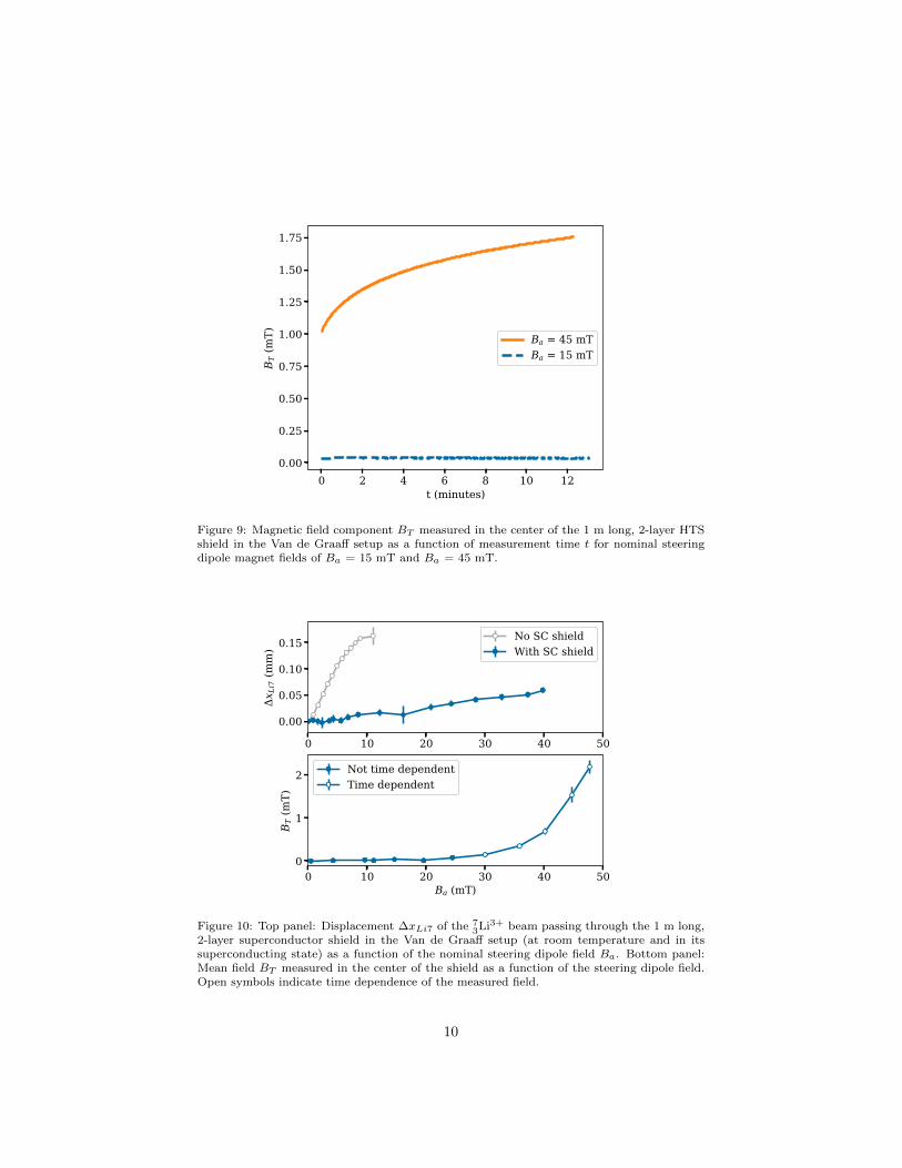
Figure 9: Magnetic field component BT measured in the center of the 1 m long, 2-layer HTSshield in the Van de Graaff setup as a function of measurement time t for nominal steeringdipole magnet fields of Ba = 15 mT and Ba = 45 mT.
Figure 10: Top panel: Displacement ∆xLi7 of the 73Li3+ beam passing through the 1 m long,
2-layer superconductor shield in the Van de Graaff setup (at room temperature and in itssuperconducting state) as a function of the nominal steering dipole field Ba. Bottom panel:Mean field BT measured in the center of the shield as a function of the steering dipole field.Open symbols indicate time dependence of the measured field.
10
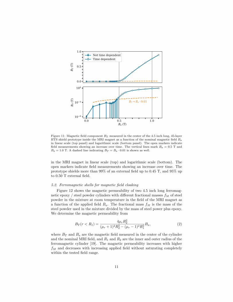
Figure 11: Magnetic field component BT measured in the center of the 4.5 inch long, 45-layerHTS shield prototype inside the MRI magnet as a function of the nominal magnetic field Ba
in linear scale (top panel) and logarithmic scale (bottom panel). The open markers indicatefield measurements showing an increase over time. The vertical lines mark Ba = 0.5 T andBa = 1.0 T. A dashed line indicating BT = Ba · 0.01 is shown as well.
in the MRI magnet in linear scale (top) and logarithmic scale (bottom). Theopen markers indicate field measurements showing an increase over time. Theprototype shields more than 99% of an external field up to 0.45 T, and 95% upto 0.50 T external field.
5.2. Ferromagnetic shells for magnetic field cloaking
Figure 12 shows the magnetic permeability of two 4.5 inch long ferromag-netic epoxy / steel powder cylinders with different fractional masses fM of steelpowder in the mixture at room temperature in the field of the MRI magnet asa function of the applied field Ba. The fractional mass fM is the mass of thesteel powder used in the mixture divided by the mass of steel power plus epoxy.We determine the magnetic permeability from
BT (r < R1) =4µrR
22
(µr + 1)2R22 − (µr − 1)2R2
1
Ba, (2)
where BT and Ba are the magnetic field measured in the center of the cylinderand the nominal MRI field, and R1 and R2 are the inner and outer radius of theferromagnetic cylinder [19]. The magnetic permeability increases with higherfM and decreases with increasing applied field without saturating completelywithin the tested field range.
11
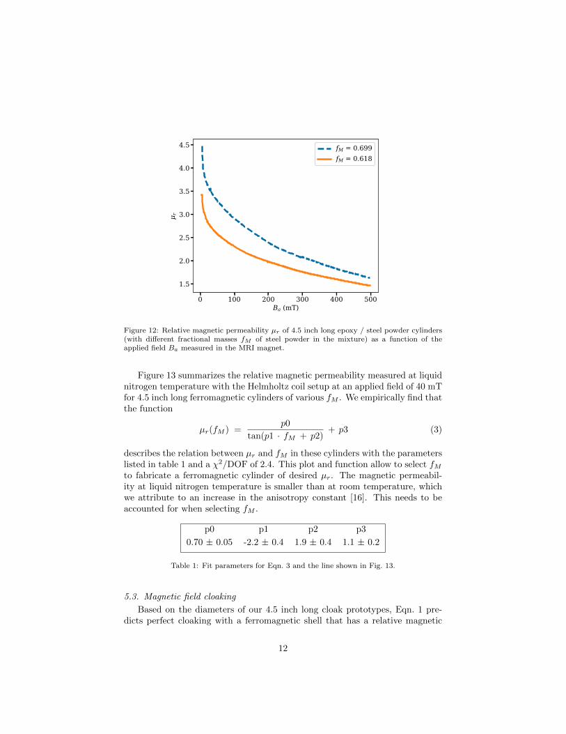
Figure 12: Relative magnetic permeability µr of 4.5 inch long epoxy / steel powder cylinders(with different fractional masses fM of steel powder in the mixture) as a function of theapplied field Ba measured in the MRI magnet.
Figure 13 summarizes the relative magnetic permeability measured at liquidnitrogen temperature with the Helmholtz coil setup at an applied field of 40 mTfor 4.5 inch long ferromagnetic cylinders of various fM . We empirically find thatthe function
µr(fM ) =p0
tan(p1 · fM + p2)+ p3 (3)
describes the relation between µr and fM in these cylinders with the parameterslisted in table 1 and a χ2/DOF of 2.4. This plot and function allow to select fMto fabricate a ferromagnetic cylinder of desired µr. The magnetic permeabil-ity at liquid nitrogen temperature is smaller than at room temperature, whichwe attribute to an increase in the anisotropy constant [16]. This needs to beaccounted for when selecting fM .
p0 p1 p2 p3
0.70 ± 0.05 -2.2 ± 0.4 1.9 ± 0.4 1.1 ± 0.2
Table 1: Fit parameters for Eqn. 3 and the line shown in Fig. 13.
5.3. Magnetic field cloaking
Based on the diameters of our 4.5 inch long cloak prototypes, Eqn. 1 pre-dicts perfect cloaking with a ferromagnetic shell that has a relative magnetic
12
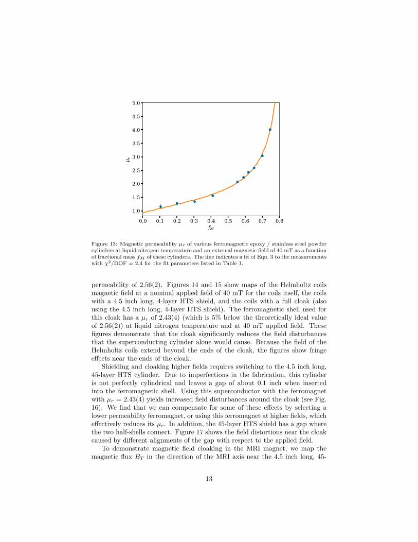
Figure 13: Magnetic permeability µr of various ferromagnetic epoxy / stainless steel powdercylinders at liquid nitrogen temperature and an external magnetic field of 40 mT as a functionof fractional mass fM of these cylinders. The line indicates a fit of Eqn. 3 to the measurementswith χ2/DOF = 2.4 for the fit parameters listed in Table 1.
permeability of 2.56(2). Figures 14 and 15 show maps of the Helmholtz coilsmagnetic field at a nominal applied field of 40 mT for the coils itself, the coilswith a 4.5 inch long, 4-layer HTS shield, and the coils with a full cloak (alsousing the 4.5 inch long, 4-layer HTS shield). The ferromagnetic shell used forthis cloak has a µr of 2.43(4) (which is 5% below the theoretically ideal valueof 2.56(2)) at liquid nitrogen temperature and at 40 mT applied field. Thesefigures demonstrate that the cloak significantly reduces the field disturbancesthat the superconducting cylinder alone would cause. Because the field of theHelmholtz coils extend beyond the ends of the cloak, the figures show fringeeffects near the ends of the cloak.
Shielding and cloaking higher fields requires switching to the 4.5 inch long,45-layer HTS cylinder. Due to imperfections in the fabrication, this cylinderis not perfectly cylindrical and leaves a gap of about 0.1 inch when insertedinto the ferromagnetic shell. Using this superconductor with the ferromagnetwith µr = 2.43(4) yields increased field disturbances around the cloak (see Fig.16). We find that we can compensate for some of these effects by selecting alower permeability ferromagnet, or using this ferromagnet at higher fields, whicheffectively reduces its µr. In addition, the 45-layer HTS shield has a gap wherethe two half-shells connect. Figure 17 shows the field distortions near the cloakcaused by different alignments of the gap with respect to the applied field.
To demonstrate magnetic field cloaking in the MRI magnet, we map themagnetic flux BT in the direction of the MRI axis near the 4.5 inch long, 45-
13

B
Figure 14: Magnetic flux BT in the direction of the Helmholtz coils axis at positions alongmeasurement lines at 1 cm distance from the cloak (4.5 inch long, 4 layer HTS and ferromagnetwith µr = 2.43(4), top panel) and across its center (bottom panel). The plots also show thefield for the coils with only the superconducting cylinder (4-layer SC) and the coils itself(reference) measured at the same positions. Vertical lines indicate the cloak dimensions.
14
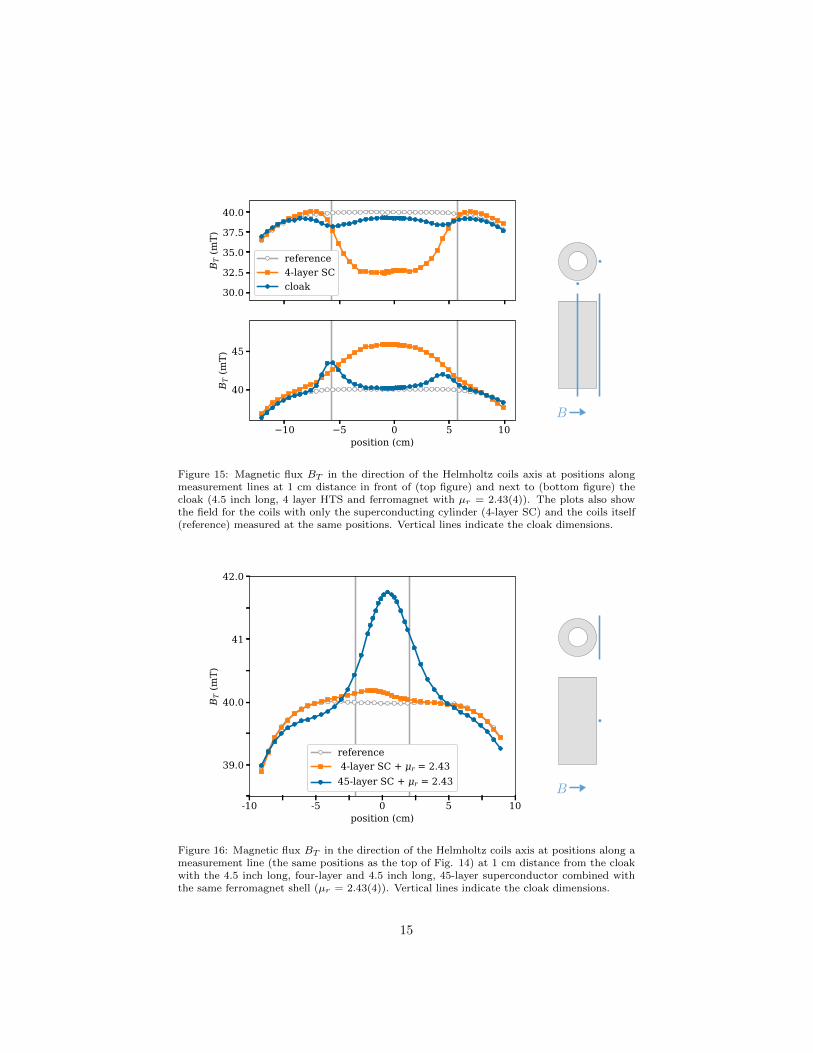
B
Figure 15: Magnetic flux BT in the direction of the Helmholtz coils axis at positions alongmeasurement lines at 1 cm distance in front of (top figure) and next to (bottom figure) thecloak (4.5 inch long, 4 layer HTS and ferromagnet with µr = 2.43(4)). The plots also showthe field for the coils with only the superconducting cylinder (4-layer SC) and the coils itself(reference) measured at the same positions. Vertical lines indicate the cloak dimensions.
B
Figure 16: Magnetic flux BT in the direction of the Helmholtz coils axis at positions along ameasurement line (the same positions as the top of Fig. 14) at 1 cm distance from the cloakwith the 4.5 inch long, four-layer and 4.5 inch long, 45-layer superconductor combined withthe same ferromagnet shell (µr = 2.43(4)). Vertical lines indicate the cloak dimensions.
15

B
Figure 17: Magnetic flux BT in the direction of the Helmholtz coils axis at positions along ameasurement line (the same positions as the top of Fig. 14) at 1 cm distance from the cloak(4.5 inch long, 45 layer HTS and ferromagnet with µr = 2.43(4)) for different angles betweenthe gap separating the two halves of the HTS shield and the magnetic field. Vertical linesindicate the cloak dimensions.
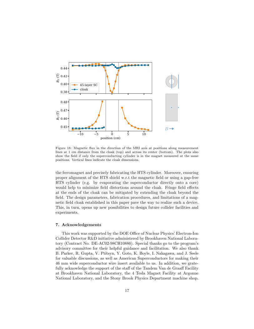
layer HTS shield and a full cloak (same HTS shield and a ferromagnetic shellwith µr = 2.43(4)). Figure 18 shows that at 0.45 T nominal MRI field, theHTS shield causes a field distortion with an amplitude of 16% of the field at1 cm distance, while the distortion near the cloak is only 2% of the applied field.The shape of this distortion hints at a misalignment of the superconductor withrespect to the MRI field (see Fig. 17). At 0.5 T nominal MRI field, the distortionamplitude is 13% of the field near the the HTS shield alone and 2% near thecloak. Figure 19 illustrates the field distortions caused by the HTS shield atup to 10 cm from the superconductor and that the cloak significantly mitigatesthese distortions.
6. Conclusion
Our tests demonstrate that a magnetic field cloak is a viable option to shieldcharged particle beams from transverse magnetic fields of up to at least 0.5 T.This allows for new designs of collider experiments and enables, for example, theuse of dipole magnets in the forward regions of an EIC detector to improve themomentum measurement of charged final state particles at angles close to thebeam line. The number of HTS layers used affects the maximum shielded field.At the same time, cooling the cloak with liquid helium instead of liquid nitrogenwould significantly increase the maximum shielded field for a given number oflayers, or would reduce the number of layers needed to shield a given field. Thecloaking performance can be maximized by carefully tuning the permeability of
16
B
Figure 18: Magnetic flux in the direction of the MRI axis at positions along measurementlines at 1 cm distance from the cloak (top) and across its center (bottom). The plots alsoshow the field if only the superconducting cylinder is in the magnet measured at the samepositions. Vertical lines indicate the cloak dimensions.
the ferromagnet and precisely fabricating the HTS cylinder. Moreover, ensuringproper alignment of the HTS shield w.r.t the magnetic field or using a gap-freeHTS cylinder (e.g. by evaporating the superconductor directly onto a core)would help to minimize field distortions around the cloak. Fringe field effectsat the ends of the cloak can be mitigated by extending the cloak beyond thefield. The design parameters, fabrication procedures, and limitations of a mag-netic field cloak established in this paper pave the way to realize such a device.This, in turn, opens up new possibilities to design future collider facilities andexperiments.
7. Acknowledgements
This work was supported by the DOE Office of Nuclear Physics’ Electron-IonCollider Detector R&D initiative administered by Brookhaven National Labora-tory (Contract No. DE-AC02-98CH10886). Special thanks go to the program’sadvisory committee for their helpful guidance and facilitation. We also thankB. Parker, R. Gupta, V. Ptitsyn, Y. Goto, K. Boyle, I. Nakagawa, and J. Seelefor valuable discussions, as well as American Superconductors for making their46 mm wide superconductor wire insert available to us. In addition, we grate-fully acknowledge the support of the staff of the Tandem Van de Graaff Facilityat Brookhaven National Laboratory, the 4 Tesla Magnet Facility at ArgonneNational Laboratory, and the Stony Brook Physics Department machine shop.
17

Figure 19: Magnetic flux BT in the direction of the MRI axis at positions along measurementlines at various distances from the 4.5 inch long, 45-layer HTS shield (top panel) and the cloak,i.e. the same superconductor shield surrounded by a ferromagnetic shell with µr = 2.43(4)(bottom panel). The nominal field of the MRI magnet is 0.45 T.
18
We thank S. Karthas, R. Lefferts, A. Lipski, and I. Yoon for all their valuedhelp. A significant portion of this research project was carried out by under-graduate students, and we thank D. Aviles, G. Bello Portmann, D. Bhatti,I. Bromberg, R. Bruce, J. Chang, B. Chase, E. Jiang, P. Karpov, Y. Ko, Y.Kulinich, R. Losacco, E. Michael, J. Nam, H. Powers, V. Shetna, S. Thompson,H. Van Nieuwenhuizen, and N. Ward for their contributions. Finally, we thankA. Chhugani, and the Simons Summer Research Program for enabling her toparticipate in this project as a high school student.
19
References
References
[1] F. Martin, S. J. St. Lorant, W. T. Toner, A 4-meter long superconduct-ing magnetic flux exclusion tube for particle physics experiments, Nucl.Instrum. Meth. 103 (1972) 503.
[2] F. Gomory, M. Solovyov, J. Souc, C. Navau, J. Prat-Camps, A. Sanchez,Experimental realization of a magnetic cloak, Science 335 (2012) 1466–1468.
[3] G. Giunchi, D. Turrioni, V. Kashikhin, H. Nguyen, E. Barzi, Feasibilitystudy of a MgB2 superconducting magnetic cloak, IEEE Trans. Appl. Su-percond. 26 (3) (2016) 8801005.
[4] J. Zhu, W. Jiang, Y. Liu, G. Yin, J. Yuan, S. He, Y. Ma, Three-dimensionalmagnetic cloak working from d.c. to 250 khz, Nat Commun 6.
[5] Y. Yeshurun, A. P. Malozemoff, A. Shaulov, Magnetic relaxation in high-temperature superconductors, Rev. Mod. Phys. 68 (1996) 911–949.
[6] S. Denis, L. Dusoulier, M. Dirickx, P. Vanderbemden, R. Cloots, M. Aus-loos, B. Vanderheyden, Magnetic shielding properties of high-temperaturesuperconducting tubes subjected to axial fields, Superconductor Scienceand Technology 20 (3) (2007) 192.
[7] J.-F. Fagnard, M. Dirickx, M. Ausloos, G. Lousberg, B. Vanderheyden,P. Vanderbemden, Magnetic shielding properties of high-Tc superconduct-ing hollow cylinders: model combining experimental data for axial andtransverse magnetic field configurations, Superconductor Science and Tech-nology 22 (10) (2009) 105002.
[8] J. Kvitkovic, P. Patil, S. Pamidi, J. Voccio, Characterization of 2G super-conductor magnetic shields at 40-77 K, Applied Superconductivity, IEEETransactions on 21 (3) (2011) 1477–1480.
[9] J. Karthikeyan, A. S. Paithankar, R. Prasad, N. C. Soni, Magnetic shieldingand harmonic generation in high-Tc superconducting tubes, Superconduc-tor Science and Technology 7 (12) (1994) 949.
[10] J. F. Fagnard, M. Dirickx, G. A. Levin, P. N. Barnes, B. Vanderheyden,P. Vanderbemden, Use of second generation coated conductors for efficientshielding of dc magnetic fields, Journal of Applied Physics 108 (1).
[11] J. Kvitkovic, S. Pamidi, J. Voccio, Shielding AC magnetic fields using com-mercial YBa 2 Cu 3 O 7 -coated conductor tapes, Superconductor Scienceand Technology 22 (12) (2009) 125009.
20
[12] I. Itoh, K. Kazuo, O. Hiroaki, NbTi/Nb/Cu multilayer composite materialsfor superconducting magnetic shielding-superconducting performances andmicrostructure of nbti layers-, Tech. rep., Nippon Steel (2002).
[13] M. W. Rupich, X. Li, C. Thieme, S. Sathyamurthy, S. Fleshler, D. Tucker,E. Thompson, J. Schreiber, J. Lynch, D. Buczek, K. DeMoranville, J. Inch,P. Cedrone, J. Slack, Advances in second generation high temperature su-perconducting wire manufacturing and R&D at American SuperconductorCorporation, Superconductor Science and Technology 23 (1) (2010) 014015.
[14] N. Nouri, B. Plaster, Comparison of magnetic field uniformities for dis-cretized and finite-sized cos-theta, solenoidal, and spherical coils, NuclearInstruments and Methods in Physics Research 723 (2013) 30–35.
[15] R. Cervantes, A compact magnetic field cloaking device, master thesis,Stony Brook University (2015).
[16] P. Oxley, J. Goodell, R. Molt, Magnetic properties of stainless steels atroom and cryogenic temperatures, Journal of Magnetism and MagneticMaterials 321 (14) (2009) 2107 – 2114.
[17] K. N. Rozanov, A. Osipov, D. Petrov, S. Starostenko, E. Yelsukov, Theeffect of shape distribution of inclusions on the frequency dependence ofpermeability in composites, Journal of Magnetism and Magnetic Materials321 (7) (2008) 738–741.
[18] K. Capobianco-Hogan, A. Adhyatman, G. Arrowsmith-Kron, G. B. Port-mann, D. Bhatti, R. Cervantes, B. Coe, A. Deshpande, N. Feege, S. Jeffas,T. Krahulik, J. LaBounty, T. LaByer, A. Oliveira, H. Powers, R. Sekelsky,V. Shethna, N. Ward, H. van Nieuwenhuizen, Magnetic cloaking of chargedparticle beams, in: Proc. of North American Particle Accelerator Confer-ence (NAPAC’16), Chicago, IL, USA, October 9-14, 2016, no. 3 in NorthAmerican Particle Accelerator Conference, JACoW, Geneva, Switzerland,2017, pp. 588–591.
[19] A. Zangwill, Modern Electrodynamics, Cambridge University Press, 2012.
21