a lightweight, multi-axis compliant tensegrity joint · a lightweight, multi-axis compliant...
TRANSCRIPT

A Lightweight, Multi-Axis Compliant Tensegrity Joint
Steven Lessard1,⇤, Jonathan Bruce1,⇤, Erik Jung1,⇤, Mircea Teodorescu1,Vytas SunSpiral2,⇤, and Adrian Agogino1,⇤
Abstract— In this paper, we present a lightweight, multi-axis
compliant tensegrity joint that is biologically inspired by the
human elbow. This tensegrity elbow actuates by shortening and
lengthening cables in a method inspired by muscular actuation
in a person. Unlike many series elastic actuators, this joint
is structurally compliant not just along each axis of rotation,
but along other axes as well. Compliant robotic joints are
indispensable in unpredictable environments, including ones
where the robot must interface with a person. The joint also
addresses the need for functional redundancy and flexibility,
traits which are required for many applications that investigate
the use of biologically accurate robotic models.
I. INTRODUCTIONFor many applications of robotic arms, flexibility and
structural compliance are critical. In unpredictable environ-ments especially, these two attributes provide robots withthe ability to robustly handle stresses. Such environmentsare common within the fields of physical therapy andwearable robotics. The oftentimes unpredictability of humanmovement necessitates a robust robot that is capable ofimprovising to awkward and inconvenient motion. Thesefeatures, however, are difficult to express through traditionalrobotics. Even typical series elastic actuators comply withimpedances only along their axes of rotation.
Some robots, however, have already explored the conceptof cable-driven robotic arms. Anthropomimetic robots likeAnthrob use compressive elements that model human bonesto support a cable network [1]. Cables are routed throughnodes to direct tensile forces along the compressive elements.Other robots such as Kenshiro have extended these principlesto an entire humanoid structure by grouping cables inbundlesto better imitate muscle fibers. These muscle groups are thenloaded onto a metal compressive frame where they can pullat the joints of the frame to produce around 70 degrees offreedom [2]. The emergence of cable-driven robotics has alsospurred the study of the dynamics and control behind saidarticulation. The network of cables can be represented as anadjacency matrix with entries corresponding to connectionsto and from each node on the robot. D. Lau et al. illustratedthat these matrices can then be operated on to approximatemotion within the cable-driven structure, thus providing amethod to controlling these often-chaotic robots [3].
*Authors with the NASA Ames Dynamic Tensegrity Robotics Lab,Moffett Field, CA 94035
1University of California, Santa Cruz, Santa Cruz, CA 95064,USA [email protected], [email protected],
[email protected], [email protected],
2Stinger Ghaffarian Technologies, Greenbelt, MD 20770, [email protected]
Fig. 1. A light-weight, multi-axis compliant tensegrity joint. This joint canactively control the pitch and the yaw of the arm to which it is attached bycontracting and releasing strings which are paired antagonistically. Theseactive string pairs can also be tuned for stiffness, creating a variable levelof flexibility within the joint.
Our approach follows a similar philosophy to the afore-mentioned robots and also actuates according to a web ofcables. Specifically, our robot adheres to the principles oftensegrity (“tensile-integrity”). Tensegrity robots are typi-cally better able to to flex under stress and absorb impactsfrom many directions [4], [5]. These hybrid soft-rigid robotsinherently resist impulses better than traditional robotic al-ternatives because their tension networks distribute appliedforces more evenly throughout the structure. As a result, evenlightweight robots can withstand relatively large impacts andloads [6].
These properties of tensegrity arms also address the needfor biomimetic robotic arms to passively handle large mo-ments applied out of phase of the main axis of rotation.Loads carried by arms can have detrimental effects onthe structure of the arm if the induced moment is largeenough. When these loads are applied at an unanticipatedangle, unprepared systems will fail. Human arms, despitetheir inherent structural levers [7], observably avoid thisshortcoming by complying with impacts from many differentangles. This emerging tensegrity theory on biomechanicsexplains this phenomenon as the arm flexibly complying withimpedances along multiple axes. The structural complianceobserved in tensegrity robots, such as ours, mitigates thisdanger by mimicking human joints and distributing loadsand stresses along multiple axes. In addition, the parallelnature of many tension elements within the tensegrity system
prevent the failure of single components from destroying theentire structure.
Our multi-axis approach (Figure 1) also has the additionalbonus of being able to articulate the arm around an atypicalaxis. Although anatomically correct human arms generateyaw motion through shoulder muscles, our robotic joint isable to generate this movement directly from the elbow.Multi-axis movement in the elbow both protects the jointfrom imposed moments and allows it a larger range ofmotion.
The flexibility and structural compliance in our particu-lar arm can be attributed to the tensegrity joint we havedeveloped. Unlike a simple hinge, this joint features twoindependent axes. Actuation along these axes control thepitch and the yaw of the end-effector of the arm. For eachaxis, we have a pair of antagonistic cables which activelycontrol motion in opposing directions around a particularaxis. In addition to these actuated cables, there are fiveadditional pairs of antagonistic, passive cables in the jointfor stability and force distribution. The pairing scheme ofour tensegrity joint is inspired by the muscular and fascialconnections within the human elbow. Because all actuatedmovement of the joint is generated by pulling and releasingcables, the motors can be located off of the robot itself. Thislightens the weight of the robotic arm, allowing it to beactuated more easily.
In this paper, we first discuss the background that demandsa more flexible and compliant robotic joint. Then, we presentthe design of our system: both the specific layout of theelbow and the methods to control it. We then show how weuse the NASA Tensegrity Robotics Toolkit (NTRT) simulatorfor rapid design and testing of tensegrity joints. Next, weillustrate the capabilities of our constructed model as well asthe hardware we have used to verify our simulated results.We conclude with a summary of our contribution as well asthe focus of future work.
II. BACKGROUND INFORMATION
A. Biological Inspiration
In human joints, bones, muscles, and fascia connect toform intricate, heterogenous systems. Each type of tissueis unique in both its structural and material properties. Be-cause of this diversity, human joints support many functionswhich range in strength, precision, and support. These jointsare also simultaneously durable and structurally compliant,improving their ability to react to impedances. Althoughrelatively little research has been performed regarding fasciaas a major component when building human-based roboticsytems [8], its role as a connector between major compres-sion elements in the body (i.e. bones) and major tensionelements within the body (i.e. muscles) cannot be overlookedwhen designing biomimetic joints. Robots that possess theseabilities can likewise accomplish numerous, and often unan-ticipated, tasks.
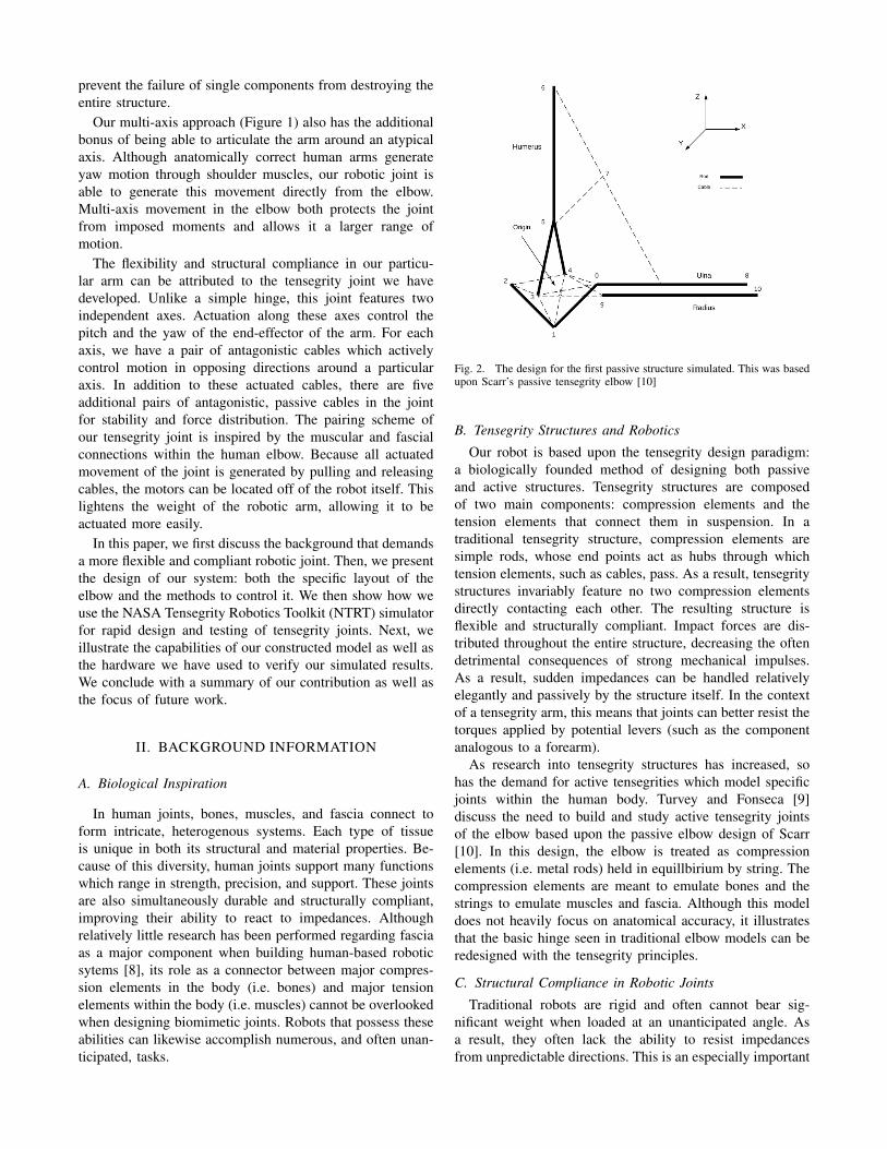
Fig. 2. The design for the first passive structure simulated. This was basedupon Scarr’s passive tensegrity elbow [10]
B. Tensegrity Structures and RoboticsOur robot is based upon the tensegrity design paradigm:
a biologically founded method of designing both passiveand active structures. Tensegrity structures are composedof two main components: compression elements and thetension elements that connect them in suspension. In atraditional tensegrity structure, compression elements aresimple rods, whose end points act as hubs through whichtension elements, such as cables, pass. As a result, tensegritystructures invariably feature no two compression elementsdirectly contacting each other. The resulting structure isflexible and structurally compliant. Impact forces are dis-tributed throughout the entire structure, decreasing the oftendetrimental consequences of strong mechanical impulses.As a result, sudden impedances can be handled relativelyelegantly and passively by the structure itself. In the contextof a tensegrity arm, this means that joints can better resist thetorques applied by potential levers (such as the componentanalogous to a forearm).
As research into tensegrity structures has increased, sohas the demand for active tensegrities which model specificjoints within the human body. Turvey and Fonseca [9]discuss the need to build and study active tensegrity jointsof the elbow based upon the passive elbow design of Scarr[10]. In this design, the elbow is treated as compressionelements (i.e. metal rods) held in equillbirium by string. Thecompression elements are meant to emulate bones and thestrings to emulate muscles and fascia. Although this modeldoes not heavily focus on anatomical accuracy, it illustratesthat the basic hinge seen in traditional elbow models can beredesigned with the tensegrity principles.
C. Structural Compliance in Robotic JointsTraditional robots are rigid and often cannot bear sig-
nificant weight when loaded at an unanticipated angle. Asa result, they often lack the ability to resist impedancesfrom unpredictable directions. This is an especially important

problem since many traditional robotic joints have only oneaxis per joint. For robots in environments where not everyimpedance can be predicted, like when imitating humanactivity, the structure of that robot must be able to endureunanticipated forces. This handling can be done activelythrough intelligent control or passively through structuralcompliance.
Series elastic actuators are one solution to passiveimpedance resistance. These actuators are built with anelastic, like a spring, along their axis of actuation. Thesesprings serve as a cushion which can resist sudden strains,thus preventing system failure. One downside of these com-ponents is that they are only able to resist strains alongtheir axis of actuation. In systems where forces may notnecessarily be applied along this axis, the internal springdoes little to mitigate the shock.
Other solutions to the problem of structural compliance liein the materials used for the actuator. Pneumatic actuators,like McKibbens artificial muscles, inflate and deflate elasti-cally [11]. In this regard, they function very similarly to theskeletal muscle found in many animals. Some soft robots areconstructed using soft materials, such as dielectric elastomers[12]. These actuators distribute stresses throughout theirstructure well, but are limited in their flexibility.
While these solutions seek to improve the compliance ofactuators, the tensegrity principle offers a solution on thestructural level. They are designed to be passively stable andsince all tension elements are connected in a network, eachstrain on a tension element propagates to the other tensionelements. As a result, robots which adhere to the tensegrityprinciples can resist impedances in multiple dimensions.
III. SYSTEM DESIGN AND CONTROL
To construct the tensegrity structure behind our light-weight, multi-axis joint, we defined the characteristics andplacement of the compression elements and the tension ele-ments. After multiple iterations of design, we developed thefollowing structure which enables actuation along multipleaxes within a single elbow joint.
A. Compression ElementsThe designs of the three compression elements (made
of plastic and carbon filament, in our prototype) in thetensegrity elbow are inspired by human arm bones. Ourelbow, however, segregates compression elements slightlydifferently than true bones in the human arm. The first com-pression element mimics the humerus and is located abovethe elbow joint itself. The compression element within thetensegrity joint is analogous to the olecranon (the hook end ofthe ulna). The third and final compression element condenseswhat would be the radius and the ulna into a single piece,forming the ”forearm” of the tensegrity arm. This particularpartitioning of compression within the arm was determinedafter iterating over multiple designs. This design alone fea-tured a centralized joint within which multiple degrees offreedom were realized. To achieve this, we diverted fromthe true anatomy of the arm by “dettaching” the olecranon
from the forearm. The rationale behind this choice was thatwe found a way to maintain the observed function of theolecranon (i.e. connecting the humerus to the forearm) whilesupplying the arm as a whole with the mechanisms necessaryto implement a two degree-of-freedom joint with passiveelements for stability. This added ability does not exist withinbiological elbows (such movement is performed by shoulder,back, and chest muscles), but it does enhance the capabilityof our constructed arm. These compression elements definethe overall structure of the arm while anchoring and routingthe tension elements.
B. Tension ElementsThe tension elements (strings, in our physical prototype)
in this design can be segregated into one of two categories:active and passive.
Active strings are coupled into antagonistic pairs, mimick-ing how many muscles, including those in the human arm,are organized. For every contraction of an active string, itscorresponding antagonistic string will relax and lengthen.In the biceps and triceps specifically, these two musclescoactivate each other. As a result, the flexure of one musclemodulates the workload of the other muscle, allowing forvariable strength and precision in movement along thatparticular degree of freedom.
The passive strings in the model approximate the fascialconnections of the elbow as well as the tendons and theligaments. There are five pairs of these passive tensionelements, which are arranged to absorb impact from alarge variety of angles. These tension elements elasticallydeform according to the actuation of the active muscles andspring the arm back into its original position of equilibrium.Although these strings are never directly controlled by amotor, they play a crucial role in stabilizing the arm as awhole. The added tensile connections also abosorb shock,preventing the destruction of the active tensile componentsor even the compression elements.
IV. SIMULATIONA. NASA Tensegrity Robotics Toolkit
To simulate our tensegrity joint, we used NASA’s Tenseg-rity Robotics Toolkit (NTRT). NTRT is an open-sourcesimulator for the design and control of tensegrity structuresand robots which has been built ontop of the Bullet PhysicsEngine (version 2.82)1. Real-time video can also be recordedwith NTRT.
In order to create structures within the toolkit, a setof builder tools are utilized which specify geometric rodsand connecting cables as a set of Cartesian coordinates.These structures can then be specified as substructures andmanipulated in three dimensional space as necessary to buildcomplex tensegrity structures (Figure 3).
F = �kX � bV (1)
1Additional information about NTRT can be found athttp://irg.arc.nasa.gov/tensegrity/NTRT

Fig. 3. An elbow constructed in NTRT. The bold colored cylinders arecompression elements and the thinner red lines connected to their end pointsare the cables (tension elements).
Within the simulator, cables are modeled as two connectedpoints whose medium lengthens and shortens according toHooke’s Law for linear springs with a linear damping termas well (Equation 1). Cable control is dictated by functionswithin a controller class, meaning that the exact length ofthe cable can be set at each timestep according to a controlpolicy. Real-world limitations, such as the max accelerationof the motor used and the target velocity of cable lengtheningare added to the simulation as well at the structural level.In addition, maximum and minimum lengths can be appliedto each individual cable to prevent unnatural deformations.These features assert that the robot in simulation is nevergiven extraordinary means to accomplish its goal. The useof NTRT has already been shown in previous papers to haveproduced accurate statics and dynamics for SUPERBall, atensegrity rover designed for extraterrestrial missions [13],[14]. As a result, these simulated robots are able to retainrealism.
In addition to modeling the physical aspects of tensegritystructures, NTRT is also useful for testing control policies.A controller, whether that is a simple, closed-loop periodicfunction or a more complex machine learning algorithm, candictate the desired forces in each of the simulated cables, andconsequently the desired lengths of each of those cables. Byalso implementing restrictions on cable lengths, the full reachof the arm can be tested via simulation. These simulatedmodels can illustrate the flexibility and compliance in eachvariation of the robot as they form different poses.
The simulation can also track changes in string lengthssimilar to how the encoders in the physical prototype mea-sure change in string length. This common feature meansthat control policies developed in simulation are more easilyportable to the physical prototype.
V. RESULTS AND DISCUSSIONA. Actuation Capability
With our joint, we have demonstrated the ability to rotatean arm around two axes independently (Figure 4). By con-tracting and releasing tension elements, we can change boththe pitch and the yaw of our tensegrity arm.
Pitch motion is achieved by changing the lengths of thestrings in the antagonistic pair of strings highlighted in Figure
Fig. 4. The movement of the end-effector of our simulated tensegrityarm with respect to time. The plotted path illustrates the effect of thejoint as it demonstrates pitch motion and then yaw motion. Since theactuation of tension elements effect their neighboring tension elementseasily, oscillations propagate quickly when moving tensegrity structures.
Fig. 5. A simulated tensegrity elbow demonstrating pitch movement. Twocables (orange and blue), mimicking the bicep and tricep in function, actas the antagonistic pair responsible for generating this movement.
5: one string is shortened while the other is elongated. Themotion shown in this figure mimics bicep contraction andtricep extension.
The yaw of the tensegrity arm is a function of the lengthsof the strings in the antagonistic pair of strings highlighted inFigure 6. one string is shortened while the other is elongated.Unlike the demonstrated pitch movement, yaw motion inthe elbow does not have a true anatomical corrollary. Yawrotation in the human arm is not generated in muscleswhich connect to the elbow joint, it is instead generated atthe shoulder joint. This gives our tensegrity elbow greatermechanical capability than biological elbows in that aspect.
B. Hardware Validation of Software ModelsAfter developing the software models of our tensegrity
joint, we proceeded to validate these results by constructingphysical models. These models were mostly constructed by3D-printing compression elements out of polylactic acid(PLA) and by connecting them with either simple string orbraided spectra string. The result was both passive models

Fig. 6. A simulated tensegrity elbow demonstrating yaw movement. Unlikepitch movement, yaw movement is not generated in the elbow, but insteadin the shoulder in an anatomically accurate human arm. The antagonisticcable pair is highlighted blue and orange.
Fig. 7. The simulation off of which the initial passive physical prototypeswere based. This was influenced by the designs in Figure 2
and an active model, all of which demonstrated the structuralrobustness expected of tensegrity structures.
1) Passive Models: The passive models were first con-structed to verify the claims made by Scarr [10]. Thesemodels did not use motors for actuation, but could still bemanually controlled by pulling on specific strings. Initially,we recreated a simulated version of Scarr’s designs in NTRT(Figure 7) inspired by the designs from Figure 2.
In the first generation of passive models seen in Figure 8,an elbow joint was constructed using string and elastic bands.This simple model succesfully demonstrated the ability tomove the forearm of our model while still applying externalstresses, forcing the model to comply as it moves.
The second model illustrated a miniaturized elbow jointand strings that were routed through the upper compressionelement. A basic end-effector was added to this robot thatcould carry a small payload.
In the third model, we disjointed the end of our forearm(most closely resembly the olecranon in a true elbow). Thisnew model featured an addition degree of freedom in ourjoint for moving the forearm (yaw). All active movement inthis model can be controlled through 4 strings, all of whichare routed through the top compression element.
TABLE IWEIGHT CONSTITUTION OF THE ACTIVE PROTOTYPE
PLA Arm (g) Both Motors (g) Combined55.6 416.6 472.2
Fig. 8. Three iterations of passive tensegrity elbow joints. These prototypesdemonstrate the flexibility and compliance of the tensegrity elbow withoutusing motors.
Fig. 9. The physical prototype of our tensegrity elbow. Compressionelements are composed of 3D-printed Polylactic Acid (PLA) and tensionelements are composed of spectra braided fishing line. This model is activelycontrolled by motors seen mounted off of the robot and onto the chassis.
2) Active Model: The hardware prototype (Figure 9) alsoreaffirmed the ability of keeping the arm lightweight. Areduction in weight means that the arm is more reactive toactuation and that it is inherently safer. For applications thatinvolve or interface with people, safety is an important factor.The motors were still able to actuate the arm despite beingoff-loaded onto the chassis. In this prototype, the motorsconstituted 88% of the total mass of the robot (Table I).This reduction in weight means that less power is requiredto operate the tensegrity arm.
VI. CONCLUSION, CONTRIBUTION, ANDFUTURE WORK
By expanding upon the ideas central to the passive tenseg-rity elbow model constructed by Graham Scarr, we havedeveloped an accurate software model of a new tensegrityjoint. We have further improved this model by discovering amethod in which to construct the tensegrity joint such thatis has multiple-axes of actuation. We have also found a wayto lighten the weight of the joint and the arm, thus makingthem more reactive to actuation and safer to operate around.These added features better equip the tensegrity elbow jointfor use as an articulation in bio-inspired robotic arms. Oursoftware model also provides a manner in which to test both

the mechanical properties of our robotic joint as well as theefficacy of different control policies. This simulator producesreal-time video of tensegrity joints functioning according tothe control policies they have been given. We have vali-dated these simulations by constructing physical prototypes,both passive and active. We have also begun to experimentwith complex controllers, such as ones governed by neuralnetworks, to tackle the difficult problem of efficiently andeffectively actuating an arm with precision and efficiency.
A. Applications in Physical Therapy and Wearable Robotics
The flexibility and structural compliance seen in theserobots are valuable traits when constructing human-orienteddevices. For the field of upper-limb physical therapy andprosthetics, compliant and durable systems with tune-ablestrength and support are essential. Many people who ownbody-powered or electric-powered prosthetics report thattheir current devices lack the necessary mobility and dex-terity required to perform basic tasks [15]. Users with body-powered prostheses in this study also cited poor cabling as amajor concern. Emphasizing robust joints in future wearablerobotics can potentially address this complaint among upper-limb prosthetic users. Robust joints will allow prothetics tohandle unexpected impedances and higher joint capability,properties which tensegrity joints have illustrated.
In addition, these improvements could be applied to reha-bilitative technology as well as prosthetic limbs. By betterunderstanding the underlying anatomy and its dynamics,wearable devices, such as exoskeletons, can better harmonizewith users as they perform bilateral stroke rehabilitation [16].As a result, our light-weight, multi-axis joint could be anexcellent candidate for future study of wearable roboticsas they apply to stroke rehabilitation. These discoveriesmay show the potential for our tensegrity elbow to modelbiological joints in a new manner.
B. Future Work
Our future work will explore how to more effectivelycontrol these tensegrity joints and others through machinelearning. Although simple control is currently possible, highlevel control decisions, such as moving an end-effector toa position in space while minimizing wobble within thetensegrity structure remains an open question. High levelcontrol could enable the tensegrity elbow to precisely andefficiently manipulate the arm into complex poses by usinga generalized algorithm.
In addition to improved control, we will also investigatethe possibility of combining this tensegrity joint with otherjoints in order to construct a more complete and biologicallyaccurate arm. Finding a better way to model the shoulderas a tensegrity, for example, could significantly improve thefunctionality of our current arm without sacrificing any ofthe capability of this elbow joint.
ACKNOWLEDGMENTThis material is based upon work supported by the Na-
tional Aeronautics and Space Administration under PrimeContract Number NAS2-03144 awarded to the Universityof California, Santa Cruz, University Affiliated ResearchCenter.
REFERENCES
[1] M. Jantsch, S. Wittmeier, K. Dalamagkidis, A. Panos, F. Volkart, andA. Knoll, “Anthrob–a printed anthropomimetic robot,” in Proc. IEEE-RAS International Conference on Humanoid Robots (Humanoids),2013.
[2] Y. Nakanishi, Y. Asano, T. Kozuki, H. Mizoguchi, Y. Motegi, M. Os-ada, T. Shirai, J. Urata, K. Okada, and M. Inaba, “Design concept ofdetail musculoskeletal humanoid kenshiro-toward a real human bodymusculoskeletal simulator,” in Humanoid Robots (Humanoids), 201212th IEEE-RAS International Conference on. IEEE, 2012, pp. 1–6.
[3] D. Lau, D. Oetomo, and S. K. Halgamuge, “Generalized modeling ofmultilink cable-driven manipulators with arbitrary routing using thecable-routing matrix,” Robotics, IEEE Transactions on, vol. 29, no. 5,pp. 1102–1113, 2013.
[4] R. Motro, “Structural morphology of tensegrity systems,” ASIANJOURNAL OF CIVIL ENGINEERING BUILDING AND HOUSING,vol. 10, no. 1, pp. 1–19, 2009. [Online]. Available: http://www.sid.ir/En/VEWSSID/J\ pdf/103820090102.pdf
[5] E. Fest, K. Shea, I. F. C. Smith, and M. Asce, “Active TensegrityStructure,” Journal of Structural Engineering, vol. 130, no. 10, pp.1454–1465, 2004.
[6] R. E. Skelton and M. C. De Oliveira, Tensegrity Systems, 2009th ed.Springer, Jun. 2009.
[7] R. Dern, J. M. Levene, and H. Blair, “Forces exerted at different ve-locities in human arm movements,” American Journal of Physiology–Legacy Content, vol. 151, no. 2, pp. 415–437, 1947.
[8] J. van der Wal, “The architecture of the connective tissue in themusculoskeletal systeman often overlooked functional parameter asto proprioception in the locomotor apparatus,” International journalof therapeutic massage & bodywork, vol. 2, no. 4, p. 9, 2009.
[9] M. T. Turvey and S. T. Fonseca, “The medium of haptic perception:A tensegrity hypothesis,” Journal of motor behavior, vol. 46, no. 3,pp. 143–187, 2014.
[10] G. Scarr, “A consideration of the elbow as a tensegrity structure,”International Journal of Osteopathic Medicine, vol. 15, no. 2, pp. 53–65, 2012.
[11] B. Tondu, “Modelling of the mckibben artificial muscle: A review,”Journal of Intelligent Material Systems and Structures, vol. 23, no. 3,pp. 225–253, 2012.
[12] R. Pelrine, R. D. Kornbluh, Q. Pei, S. Stanford, S. Oh, J. Eckerle,R. J. Full, M. A. Rosenthal, and K. Meijer, “Dielectric elastomerartificial muscle actuators: toward biomimetic motion,” in SPIE’s 9thAnnual International Symposium on Smart Structures and Materials.International Society for Optics and Photonics, 2002, pp. 126–137.
[13] K. Caluwaerts, J. Despraz, A. Iscen, A. P. Sabelhaus, J. Bruce,B. Schrauwen, and V. SunSpiral, “Design and control of complianttensegrity robots through simulation and hardware validation,” Journalof The Royal Society Interface, vol. 11, no. 98, p. 20140520, 2014.
[14] B. T. Mirletz, R. D. Quinn, and V. SunSpiral, “Cpgs for adaptivecontrol of spine-like tensegrity structures.”
[15] D. J. Atkins, D. C. Heard, and W. H. Donovan, “Epidemiologicoverview of individuals with upper-limb loss and their reported re-search priorities.” JPO: Journal of Prosthetics and Orthotics, vol. 8,no. 1, pp. 2–11, 1996.
[16] J. Rosen and J. C. Perry, “Upper limb powered exoskeleton,” Inter-national Journal of Humanoid Robotics, vol. 4, no. 03, pp. 529–548,2007.