a guide to using logicator - new-media-learning
TRANSCRIPT

1
A guide to using
Logicator flowchart control software
© New Media Learning Ltd 2009.
No part of this publication may be reproduced, stored in a retrieval system, or transmitted in
any form by any means, without prior permission of the copyright holder.
Copyright is waived in the following circumstances: small number of copies may be made for
use only in the purchaser’s school.
These copies may not be sold or made available outside the purchaser’s school.

2
Contents
Overview............................................................................................................................................................ 4
The main work area in Logicator ....................................................................................................................... 4
Connecting an Interface .................................................................................................................................... 5
Selecting the Interface Type .............................................................................................................................. 5
Selecting the COM number ............................................................................................................................... 6
The Toolbar menu ............................................................................................................................................. 7
Menu Options................................................................................................................................................. 7-8
Creating a flowsheet.......................................................................................................................................... 9
The Command menu ........................................................................................................................... 9
The Flowsheet work area .................................................................................................................... 9
The Map .............................................................................................................................................. 9
Adding a command cell ....................................................................................................................... 9
Cell Details Dialogue Box ..................................................................................................................... 9
Labelling a command .......................................................................................................................... 9
Deleting a command ........................................................................................................................... 9
Moving commands.............................................................................................................................. 9
Cutting, Copying and Pasting............................................................................................................. 10
Selecting a block of commands ......................................................................................................... 10
Moving a selected block.................................................................................................................... 10
Routes ............................................................................................................................................... 10
Drawing Routes ................................................................................................................................. 10
Deleting Routes ................................................................................................................................. 11
Inserting Commands ......................................................................................................................... 11
Inserting Rows ................................................................................................................................... 11
Deleting Rows.................................................................................................................................... 11
Inserting Columns.............................................................................................................................. 11
Deleting Columns .............................................................................................................................. 11
Decision commands and their routes................................................................................................ 11
Drawing routes from a Decision command....................................................................................... 11
Instrument Panels
The Digital Panel................................................................................................................................ 12
The Analogue Panel........................................................................................................................... 12
The Variables Panel ........................................................................................................................... 12
The Time Panel .................................................................................................................................. 12
The Graph Window ........................................................................................................................... 13
Log command. ................................................................................................................................... 13
Common commands
Start command.................................................................................................................................. 14
Stop command. ................................................................................................................................. 14
Outputs command ............................................................................................................................ 14
Motor command ............................................................................................................................... 14
Wait command .................................................................................................................................. 14
Decision command. ........................................................................................................................... 15

3
Comment command.......................................................................................................................... 14
Sound command ............................................................................................................................... 14
Count command................................................................................................................................ 14
Log command .................................................................................................................................... 14
Decision command. ........................................................................................................................... 15
Variables
Compare command........................................................................................................................... 16
Expression command. ....................................................................................................................... 16
Inc command..................................................................................................................................... 16
Dec command ................................................................................................................................... 16
Input command ................................................................................................................................. 17
In command....................................................................................................................................... 17
Out command.................................................................................................................................... 17
Procedures
DoProc command.............................................................................................................................. 18
Procedure command......................................................................................................................... 18
End command ................................................................................................................................... 18
Interrupt command ........................................................................................................................... 19
Interrupt Setup command................................................................................................................. 19
Animation
Play command ................................................................................................................................... 20
Message command. .......................................................................................................................... 20
Hide Message command ................................................................................................................... 20
Picture command .............................................................................................................................. 20
Hide Picture command...................................................................................................................... 20
4
Overview Logicator provides a graphical environment for designing, testing, editing and downloading control
algorithms in the form of a stylised flowchart. A flowchart can be run as a program to control
electrical circuits, robots and model systems via an interface, or simulated on-screen systems.
The range of Logicator commands supports a range of control functions to provide function to
output devices, such as motors and lamps. We can switch devices on or off in sequences using:
timing, counting, repetition, and decisions based on signals from digital and analogue sensors.
Programming using Logicator can take either a top-down (system-level design) approach or a
bottom-up (experimental) approach. The ease with which sections of tested code can be moved to
form procedures, or sub-programs, supports these approaches.
For up-to-date information about Logicator please visit www.logicator.net
Please note that Junior Logicator uses a smaller set of commands to those described in this guide.
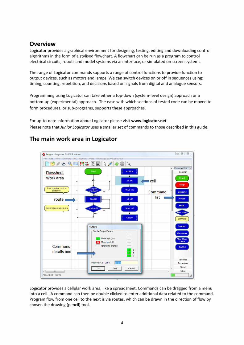
The main work area in Logicator
Logicator provides a cellular work area, like a spreadsheet. Commands can be dragged from a menu
into a cell. A command can then be double clicked to enter additional data related to the command.
Program flow from one cell to the next is via routes, which can be drawn in the direction of flow by
chosen the drawing (pencil) tool.

5
Connecting an interface
Interface Types The following Interfaces or control boxes can be used with Logicator:
Economatics Smart Box
Economatics Control Station
Economatics Discovery
Fischertechnik Intelligent Interface 30402
Fischertchnic Robo Interface 93293
Lego Interface B
Lego Mindstorms RCX
Lego Mindstorms Scout
Lego Mindstorms NXT
Deltronics Control and Datacapture
Deltronics Serial Interface
Deltronics Junior Interface
Deltronics Control IT (& Serial Adapter)
Deltronics Control IT (& Extra Sense)
Commotion Coco USB Interface (plastic case)
Commotion Coco USB Interface (metal case)
Commotion Coco Serial Interface
Commotion Coco Junior Interface
Data Harvest FlowGo
Data Harvest Contact Controller
Data Harvest Contact Controller Plus
Unilab Serial Computer Module 540.027
Please contact the publisher for information about any interfaces not mentioned above.
Please note that some of the above interface choices will work with other control boxes not on this
list. For example, the Deltronics control boxes have been supplied under a range of other names.
Selecting the Interface Type
To select an Interface type for a Logicator flowsheet to control choose Options > Setup Interface.
The following dialogue window will appear:
In Step 1 choose the required Interface or control box from the drop-down list.
In Step 2 choose the cable type that connects the interface to the computer.
In Step 3 choose the COM (communication port) number used by your computer.
In Step 4 (if not greyed out) choose the required numbering of the input and output bits (either 0-7 or 1-8) and
identify the names of the sensors attached to the four analogue inputs.
Then choose ‘Save’, or ‘Save and Connect’ to immediately connect the control box.
6
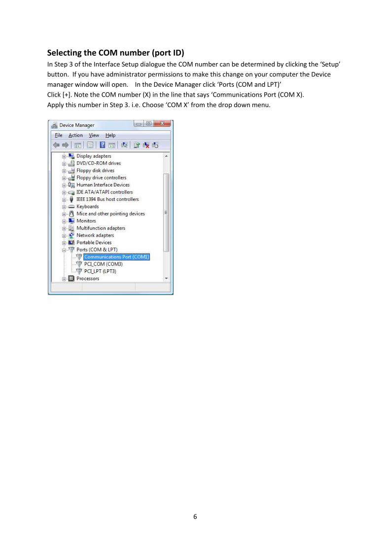
Selecting the COM number (port ID)
In Step 3 of the Interface Setup dialogue the COM number can be determined by clicking the ‘Setup’
button. If you have administrator permissions to make this change on your computer the Device
manager window will open. In the Device Manager click ‘Ports (COM and LPT)’
Click [+]. Note the COM number (X) in the line that says ‘Communications Port (COM X).
Apply this number in Step 3. i.e. Choose ‘COM X’ from the drop down menu.
7
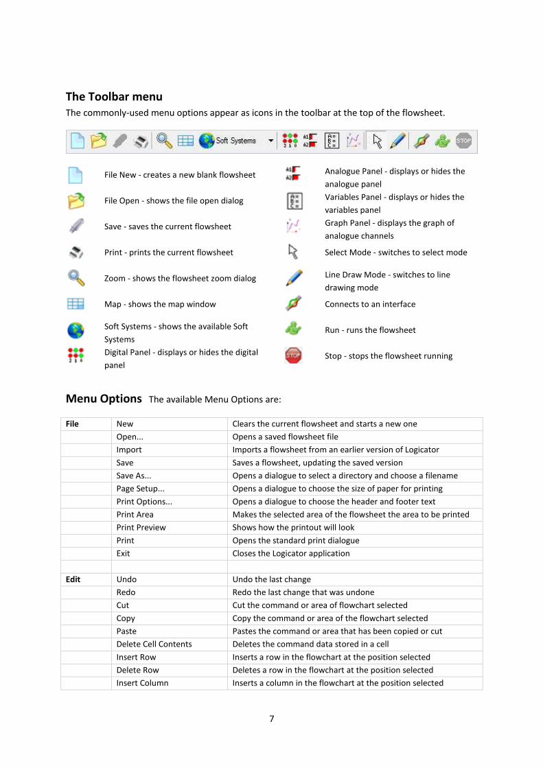
The Toolbar menu
The commonly-used menu options appear as icons in the toolbar at the top of the flowsheet.
File New - creates a new blank flowsheet
Analogue Panel - displays or hides the
analogue panel
File Open - shows the file open dialog
Variables Panel - displays or hides the
variables panel
Save - saves the current flowsheet
Graph Panel - displays the graph of
analogue channels
Print - prints the current flowsheet
Select Mode - switches to select mode
Zoom - shows the flowsheet zoom dialog
Line Draw Mode - switches to line
drawing mode
Map - shows the map window
Connects to an interface
Soft Systems - shows the available Soft
Systems Run - runs the flowsheet
Digital Panel - displays or hides the digital
panel
Stop - stops the flowsheet running
Menu Options The available Menu Options are:
File New Clears the current flowsheet and starts a new one
Open... Opens a saved flowsheet file
Import Imports a flowsheet from an earlier version of Logicator
Save Saves a flowsheet, updating the saved version
Save As... Opens a dialogue to select a directory and choose a filename
Page Setup... Opens a dialogue to choose the size of paper for printing
Print Options... Opens a dialogue to choose the header and footer text
Print Area Makes the selected area of the flowsheet the area to be printed
Print Preview Shows how the printout will look
Print Opens the standard print dialogue
Exit Closes the Logicator application
Edit Undo Undo the last change
Redo Redo the last change that was undone
Cut Cut the command or area of flowchart selected
Copy Copy the command or area of the flowchart selected
Paste Pastes the command or area that has been copied or cut
Delete Cell Contents Deletes the command data stored in a cell
Insert Row Inserts a row in the flowchart at the position selected
Delete Row Deletes a row in the flowchart at the position selected
Insert Column Inserts a column in the flowchart at the position selected

8
Delete Column Deletes a column in the flowchart at the position selected
Swap yes and no Swaps the 'yes' and 'no' routes from a decision command
View Digital Panel Shows or hides the Digital Panel
Analogue Panel Shows or hides the Analogue Panel
Variables Panel Shows or hides the Variables Panel
Graph Panel Shows or hides the Graph Panel
Time Panel Shows or hides the Time Panel
Map Window Shows or hides the Map Window
Show Grid Shows or hides the grid which shows cell positions
Status Bar Display Shows the status bar display below the flowsheet window
Zoom... Displays the flowsheet at 50% 75% 100% or 125% of its size
Refresh Updates the screen and settings
Simulation Run Runs the flowsheet as a program
Remote Run Runs the flowsheet remotely (for remote-operating interfaces)
Stop Stops the running of the flowsheet
Set Run Speed... Sets the delay time between each command
Interface Connects or disconnect the selected interface
Soft Systems Lists the available Soft System simulations
Options
Setup Interface... Allows an interface to be selected and interface settings selected.
Show COM ports... Shows the active communications ports on this computer
Language Changes the language that is used by the program
Grid Size Allows the size of the Flowsheet grid to be changed
Hide Panels Whilst Drawing Changes the language that is used by the program
Drawing Guide Lines Provides a guide line whilst drawing routes
Line Drawing Tooltips Provides tooltips when drawing routes
Help Contents Displays these online help pages
Soft System Help Shows the help Guide for each of the available Soft Systems
Soft Systems Guide Shows a general guide to the Soft Systems teaching materials
Register Register your copy of Logicator (if unregistered)
About Provides details of this application
9
Creating a flowsheet
The Command menu
The command menu can be
set to ‘autohide’ by clicking
the thumb pin icon.
Commands are grouped into
four categories in the
command list menu.
The commonly-used
commands are shown in the
‘Common’ menu.
Click the other menu
headers to reveal the other
categories of command.
Commands are used by
dragging them onto an
unoccupied cell on the
flowsheet grid.
The Flowsheet work area Cells are arranged in rows and columns. Each
flowsheet has 22 columns and 25 rows. The
default screen shows just 12 columns and 12
rows. Use the View>Zoom menu if you want
to change the number of cells visible on the
screen.
The Map
The Map option allows you to view the whole
of the flowsheet at once. The red square
marks the area currently displayed on the
screen.
Adding a Command cell To add a command cell to a flowsheet, drag
the required command from the Commands
List and place it in an unoccupied cell.
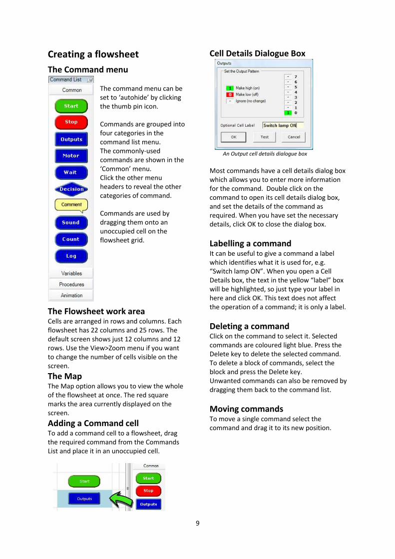
Cell Details Dialogue Box
An Output cell details dialogue box
Most commands have a cell details dialog box
which allows you to enter more information
for the command. Double click on the
command to open its cell details dialog box,
and set the details of the command as
required. When you have set the necessary
details, click OK to close the dialog box.
Labelling a command It can be useful to give a command a label
which identifies what it is used for, e.g.
“Switch lamp ON”. When you open a Cell
Details box, the text in the yellow “label” box
will be highlighted, so just type your label in
here and click OK. This text does not affect
the operation of a command; it is only a label.
Deleting a command Click on the command to select it. Selected
commands are coloured light blue. Press the
Delete key to delete the selected command.
To delete a block of commands, select the
block and press the Delete key.
Unwanted commands can also be removed by
dragging them back to the command list.
Moving commands To move a single command select the
command and drag it to its new position.

10
Cutting, Copying and Pasting Use the Cut, Copy and Paste options from the
Edit menu to cut or copy selected commands,
or blocks of commands, and paste them
either into another part of the flowsheet.
Alternatively, you can copy commands, or
blocks of commands, within a flowsheet by
first selecting them and then holding down
the Ctrl key as you drag them to their new
position. Remember that copied commands
will retain their existing cell details.
Selecting a block of commands Click on the top left corner of the block of
cells. Hold down the Control Key (CTRL) and
click on the lower right corner of the range of
cells.
A block of commands in the selection frame
Selected commands are coloured light blue.
To deselect commands, click on another part
of the flowsheet.
Moving a selected block To move the block of selected commands,
drag the top command to the top position in
the new area. Once placed, move the pointer
away to have them placed and redrawn.
Routes Routes can be drawn through the middle of a
cell, or in either one of the two rails between
cells. Routes must be drawn in the direction
that you want flow to take when the
flowsheet runs.
Drawing Routes
Click on the Line Drawing icon on the
toolbar to select drawing mode.
The mouse cursor changes to a pen icon.
Click at a command cell where the line should
start. Now move the pointer along the route
you wish to draw. A dotted line will show
where the route will be drawn. At a corner
click again and continue moving the pointer
until you reach the end of the desired route.
Routes can be drawn through cells or between rails.
Click to complete the route, then Right Click
to end drawing mode.
Drawing mode can also be deselected
by clicking the arrow icon.
Drawing mode can also be selected by right
clicking a command and choosing Start Line
from the submenu.
Routes can only be drawn vertically or
horizontally. Always draw the route in the
direction of the flow, as indicated by the
arrows.
Hot tip
By holding down the Control key, the arrow
keys can also be used to draw lines.

11
Deleting Routes Click at the beginning of the route to be
deleted, and press the Delete key. When you
draw a new route from a command, the
existing route from the command will
automatically be deleted. To delete a route
without deleting the command in which it
starts: first click on the command to select it.
Then hold down the Ctrl key as you press the
Delete key.
Inserting Commands To insert a command into a block of
commands, simply drag the command and
place it in the desired position in the block of
commands. A new row will be inserted in the
flowchart at this point and the commands will
move down to allow the new command to be
positioned.
Inserting Rows
To insert a new row in your flowchart, click a
cell in that row and either choose Edit > Insert
Row, or Right Click > Insert Row.
Routes will be connected across the new row.
Deleting Rows To delete a row in your flowchart, click a cell
in that row and either choose Edit > Delete
Row, or Right Click >Delete Row.
Any commands in that row will be deleted.
Inserting Columns
To insert a new column in your flowchart,
click a cell in that column and either choose
Edit > Insert Column, or Right Click > Insert
Column. Routes will be connected across the
new column.
Deleting Columns To delete a column in your flowchart, click a
cell in that column and either choose Edit >
Delete Column, or Right Click >Delete Column.
Any commands in that column will be deleted.
Decision command and their routes
When program flow reaches a Decision cell, it
continues in either the Yes or No direction
depending on the result of the decision test.
The two types of Decision in Logicator are a
test of the digital input state, and a test of the
value of a variable (Compare command).
Drawing routes from a Decision
command The first line that you draw from a Decision
command is the “Yes” direction, and the
second line is the “No” direction.
Hot Tip
You can swap the “Yes” and “No” routes by
right clicking on the Decision and choosing
“Swap Yes/No”.

12
Instrument Panels
The Digital Panel As a flowsheet runs, the Digital Panel shows
the changing state of outputs, motors and
inputs as they would be if the flowsheet had
been downloaded to a PIC microcontroller.
To display the Digital Panel, select the
View>Digital Panel menu. Alternatively, click
the toolbar icon shown below.
Digital Panel and its toolbar icon
Simulating digital inputs
The function keys on the computer keyboard
are used to simulate inputs from digital
sensors while a flowsheet is running.
Function keys F2 to F9 will simulate digital
sensors connected to inputs 0 to 7 on a PIC
microcontroller. Key F2 simulates input 0; key
F9 simulates input 7.
Pressing the function key is equivalent to the
sensor being “on” (1). When the key is not
pressed, it is equivalent to the sensor being
“off” (0).
Clicking on the corresponding input or output
on the digital panel will also have the same
effect.
The Analogue panel
Analogue Panel and its toolbar icon
The Analogue Panel allows you to simulate
the changing reading from analogue sensors
while a flowsheet is running.
Identify the sensor (A0 to A3) which you wish
to simulate, and use the slider in the panel to
vary the simulated reading from 0 to 255.
To display the Analogue Panel, select the
View>Analogue Panel menu. Alternatively,
click the toolbar icon.
The Variables Panel If your flowsheet uses variables, it is useful to
display the Variables window when you run it.
The changing values of any of the variables A
to H that are used in the flowsheet will be
displayed as the flowsheet runs.
The Variables window
Examples:
A = A1 will store the numerical value of the
Analogue port A1.
‘In A’ will read the input port bit values in the
variable A
The Time Panel The Time window sits below the command
window. It shows the value of the variable
‘Time’ during the run of the flowsheet. The
variable ‘Time’ can be used in an expression
command, e.g. A = Time, or it can be reset
with the expression Time = 0.

13
The Graph Window
The graph window will plot the current values
of analogue variables A0 – A3. It is a self-
contained data logger with menu items that
allow data logging to be started and stopped,
the data recorded shown and saved, and
statistics of the log viewed.
The Graph Window can be turned on from its
window menu: Log > Start, and turned off
with: Log > Stop. Log > Settings will open a
dialogue box to allow the inputs, scale and
sample rate to be selected.
The graph window can be resized to become
the dominant window in Logicator. The main
Logicator window can be minimised so that
the application appears to operate singly as a
data-logger.
The menu item Log > Settings provides the
following window. This allows inputs to be
selected, pen colours and line width to be
changed and the rate of sampling selected.
Log command
The Graph Window is usually used with the
Log command. The cell details box for this
command is similar to the Settings dialogue,
except that the sample rate corresponds to
readings being taken each time program flow
passes through the Log command.
The graph produced can be copied with the
Edit > Copy Graph menu option, and then
pasted into a document.
The menu item View > Data will show, in a
new window, the data logged.
The menu item View > Statistics will show, in
a new window, the statistics for each channel
logged.

14
Common commands
Start command A START command marks
the point where the
flowsheet starts running.
When the Start icon is clicked the flowsheet
starts at the START command. Every
flowsheet must have a START command.
Stop command A flowsheet will stop
running whenever a STOP
command is reached.
Only use one Start and one Stop command in
any flowsheet.
Outputs command
An Outputs command is used
to switch on or off any
output devices that are
connected to the interface or control box.
The Output Pattern line of its Cell Details box
shows how this command will set the 8 bits
on the output port.
Outputs command Cell Details box
Each bit labelled 0-7 can be set to switch an
output bit on or off, or to leave it in the state
it has already been set to.
This means: switch this output on.
This means: switch this output off.
This means: ignore this output,
i.e. leave it in the state in which it was
set by the previous Outputs command.
Motor command
The Motor command allows up to 4 motors to
be controlled at a time. Each motor can have
their speed set and their direction of rotation
forward, or backward, or off. If a control box
is used which doesn’t provide separate motor
driver ports the motor command will drive
the outputs as four pairs, 0+1, 2+3, 4+5, 6+7.
Motors command Cell Details box
Wait command
A Wait command makes a running flowsheet
pause for the number of seconds specified
before the next command is carried out. You
can use it to keep output devices switched on
or off for a set time. Use its Cell Details box to
enter a number of seconds or a variable A-H.
Wait command Cell Details box
15
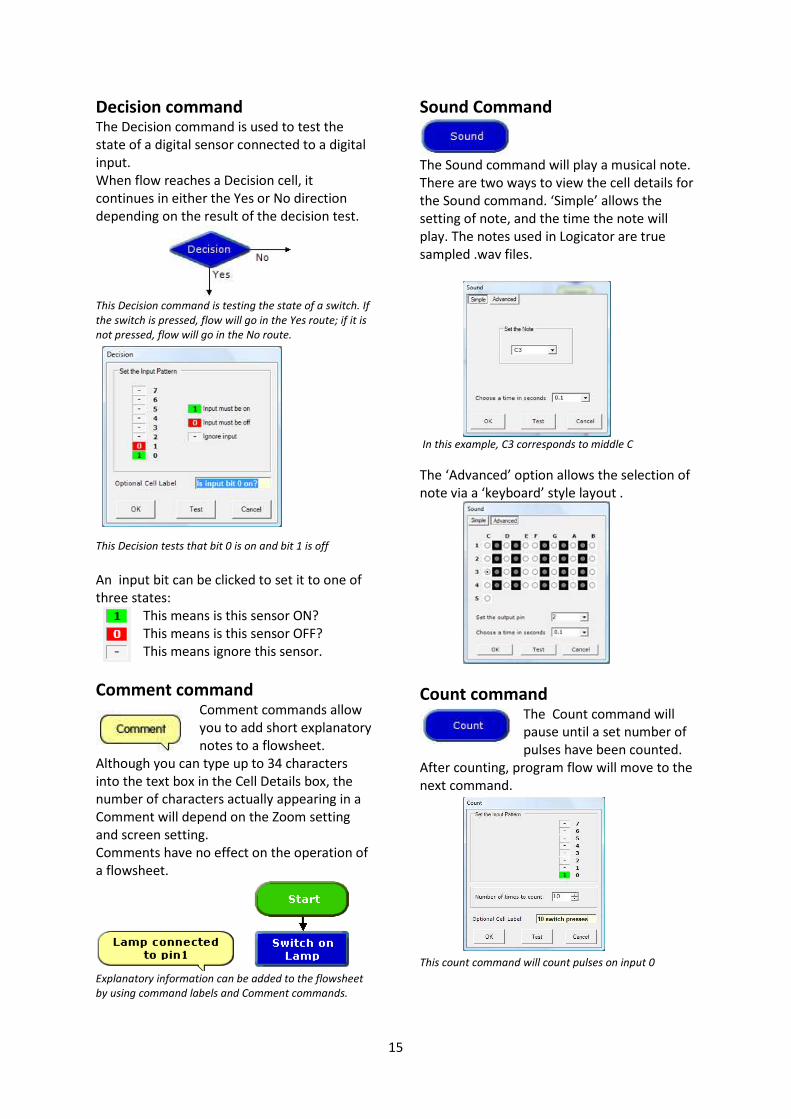
Decision command
The Decision command is used to test the
state of a digital sensor connected to a digital
input.
When flow reaches a Decision cell, it
continues in either the Yes or No direction
depending on the result of the decision test.
This Decision command is testing the state of a switch. If
the switch is pressed, flow will go in the Yes route; if it is
not pressed, flow will go in the No route.
This Decision tests that bit 0 is on and bit 1 is off
An input bit can be clicked to set it to one of
three states:
This means is this sensor ON?
This means is this sensor OFF?
This means ignore this sensor.
Comment command Comment commands allow
you to add short explanatory
notes to a flowsheet.
Although you can type up to 34 characters
into the text box in the Cell Details box, the
number of characters actually appearing in a
Comment will depend on the Zoom setting
and screen setting.
Comments have no effect on the operation of
a flowsheet.
Explanatory information can be added to the flowsheet
by using command labels and Comment commands.
Sound Command
The Sound command will play a musical note.
There are two ways to view the cell details for
the Sound command. ‘Simple’ allows the
setting of note, and the time the note will
play. The notes used in Logicator are true
sampled .wav files.
In this example, C3 corresponds to middle C
The ‘Advanced’ option allows the selection of
note via a ‘keyboard’ style layout .
Count command
The Count command will
pause until a set number of
pulses have been counted.
After counting, program flow will move to the
next command.
This count command will count pulses on input 0

16
Log command
The Log command will
record the values of
selected analogue channels
each time program flow passes through this
command. See ‘The Graph Window’ for
further details.
Variables
Compare command
The compare command is used to check the
value of a variable,
elapsed time, or a
reading from an
analogue sensor
connected to an
analogue input.
When flow reaches a Compare cell, the
software checks the current reading from the
specified sensor, and compares it with the
threshold that you have set. Flow will
continue in either the “Yes” or “No” direction
depending on the result of the comparison.
The Cell Details box of the Compare command
is shown below.
Cell Details box of the Compare command
Use box one to select the variable or sensor
that you want the command to check.
Use boxes two and three to complete the
comparison. The drop-down list in box two
contains a list of operators such as “greater
than” (>), “less than” (<), and “equals” (=).
Select the one that you require. NOTE: It is
usually better to use an operator such as
“greater than or equals” (>=) instead of
“equals”, because analogue sensor readings
can fluctuate rapidly, the sensor reading may
never actually coincide with the exact
threshold level.
Use box three to set the threshold level.
Type in a number between 0 and 255, or
select it from the drop-down list.
Note that the value to be compared can also
be another analogue reading, the value of a
variable A-H, the value of elapsed time, or a
randomly generated value.
Expression command
The Expression command is
used to set a value of a
variable A-H, or the value of
elapsed time. e.g. A=0, A=A0, A=B-C, Time=0
Inc command Each time flow passes
through an Inc command, 1
is added to the value of the
selected variable (Inc is short for increment).
This is the same as using an Expression
command to make A = A + 1.
In the Cell Details box, select which variable to
use, and click OK.
Dec command Each time flow passes
through a Dec command, 1
is subtracted from the value
of the selected variable (Dec is short for
Decrement).

17
Input command
The input command provides a way for the
user to enter a value using the keyboard when
the flowchart is running. The dialogue allows
a variable to be chosen in which to store the
value that is input.
When program flow arrives at the input
command a dialogue opens to allow a value
to be entered into the selected variable.
In command
The in command reads the value of the input
port bits and stores this value in a selected
variable. The value stored corresponds to the
state of each bit on the input port according
to the selection values in the following table:
To calculate the selection value, add up the
values for all bits that are on. e.g. if bits 0 and
2 are on the selection value would be 5.
Out Command
When flow passes through an Out command,
the output port is set to the binary value of
the number or variable entered in the
command.
The binary pattern displayed on the output
port will correspond to the bits selected by
the value in the table below.
For example, if the value to be output is 16,
then bit 4 would be turned on. If the value to
be output was 17 then bits 4 and 0 would be
turned on.
This flowsheet would cause the output port lights to
count up in binary

18
Procedures
DoProc command
The DoProc command is
short for ‘Do Procedure’. On
meeting a DoProc command,
program flow will jump to the procedure
definition (which should be already defined).
On executing the commands in the procedure
it will return to the DoProc command. The
command End marks the end of the
procedure definition.
In the cell details box for the Do Procedure
command it is also possible to set the number
of times top run the Procedure. This will
simply repeat the Do Procedure for the set
number and then continue as normal.
Procedure command
The Procedure command
marks the start of a
subroutine. A subroutine is a
self -contained mini program top and tailed by
the procedure command and the End
command.
The cell details box invites the entry of a
name for the procedure, e.g FLASH. The
Procedure name will be displayed in capital
letters to emphasise that it is effectively a
new command word.
End command
The End command marks the
end of the procedure
definition. Upon meeting this
command program flow will transfer back to
the Do Proc command.
Note that all the procedures that have been
built in a flowsheet are automatically listed in
the drop-down box in the DoProc cell details
box. When flow reaches a DoProc command,
it jumps to the Procedure command with the
same name. When the flow of control reaches
a Return command, the flow jumps back to
the Do Procedure command that called the
procedure.
The DoProc
command FLASH
calls the FLASH
procedure
New commands can be created using
procedures. If required their procedure
definitions can be ‘hidden’ at the bottom of
the flowsheet to encourage ‘top down’
development.
In this example there are four
procedures defined elsewhere in the
flowchart as a series of sounds. The
four keywords need to be placed in
the correct order to correctly hear
the tune to ‘Pop goes the weasel’.

19
Interrupt command
An Interrupt instantly
captures the flow of control
whenever a preset digital
input condition occurs to trigger it e.g. when a
switch is pressed.
This Interrupt will
trigger when a
switch on bit 0 is
pressed.
When the interrupt is triggered flow jumps
immediately to the Interrupt command and
then carries out any commands which follow
until it reaches an End command. It then
returns to the point which it was at when the
Interrupt occurred.
Interrupt Setup command
In order to use an Interrupt,
the interrupt must be
‘enabled’. This is done
through the Interrupt Setup command.
There are two options in the command –
Enable or Disable.
To prevent the Interrupt retriggering itself,
the Interrupt is automatically disabled once it
is triggered. To re-enable it another Interrupt
Setup command is required.
This Interrupt will capture program flow and play a
sound. The interrupt is then enabled once again before
returning to the point at which it left the main flow.

20
Animation
Play command
The Play command will cause
sound or video files to be
played as a flowsheet runs.
Click the Browse button to find the file you
wish to play, or type in the path to the file in
the text box.
Click Test to display the play file. At this point
you can set the size and position of the
playback window before you click OK. Video
sequences or animations will be displayed in a
window on the flowsheet (not in the Windows
Media Player). Once the file starts to play the
flowsheet will continue. The play command
will accept most Window media player type
files.
Messsage command
The Message command will
display a text message on the
screen as a flowsheet runs.
The message is displayed when program flow
passes through the MESSAGE command. It
stays on the screen until it is removed by a
HIDE MESSAGE command. Messages are
automatically
numbered.
The Message window can be positioned on
the screen during edit mode. The font sized
can also be changed.
Hide Message command
The Hide Message command
removes a specified Message
from the screen, or all messages.
Choose which
message that you
want to hide from
the drop-down list
Picture command
The Picture command will
display a picture on the screen
as the flowsheet runs. The
picture will stay on the screen until it is
removed by a Hide Picture command. Pictures
are automatically numbered. The picture box
can be placed anywhere on the screen, and its
shape can be changed by dragging from a
corner.
Hide Picture command
The Hide Picture command removes a
specified Picture from the screen. The picture
to be hid is chosen by selecting it from the
drop down box.