a guide to using ‘logicator for pic micros’ software and ... · pdf filea guide to...
TRANSCRIPT

1
A guide to using
‘Logicator for PIC micros’
software and connecting
to a PIC microcontroller
© Copyright Revolution Education Ltd. and New Media Learning Ltd 1999-2008.
PICAXE technology and portions of this document are © Copyright Revolution Education Ltd.
No part of this publication may be reproduced, stored in a retrieval system, or transmitted in
any form by any means, without prior permission of the copyright holder.
Copyright is waived in the following circumstances: small number of copies may be made for
use only in the purchaser’s school.
These copies may not be sold or made available outside the purchaser’s school.
2
Contents
Getting Started .................................................................................................................................................. 3
RM CC3 Installation ........................................................................................................................................... 3
Website.............................................................................................................................................................. 3
Support .............................................................................................................................................................. 3
Software
Overview............................................................................................................................................................ 5
Index of Logicator commands ........................................................................................................................... 6
Installing the USB driver and cable.................................................................................................................... 7
Memory Use ...................................................................................................................................................... 8
How to build, edit and test run a Logicator flowsheet ...................................................................................... 9
Commands....................................................................................................................................................... 10
How to test run a flowsheet ............................................................................................................................ 12
Displaying and using BASIC.............................................................................................................................. 13
Outputs............................................................................................................................................................ 15
Inputs............................................................................................................................................................... 21
Digital Inputs.................................................................................................................................................... 22
Analogue Inputs............................................................................................................................................... 27
Using Infrared control...................................................................................................................................... 29
Using Ultrasonic measurement ....................................................................................................................... 30
Procedures....................................................................................................................................................... 31
Variables .......................................................................................................................................................... 37
Counting .......................................................................................................................................................... 37
Timing .............................................................................................................................................................. 40
Mathematical expressions............................................................................................................................... 41
Simulations ...................................................................................................................................................... 44
3
Getting Started
Install the Logicator software onto the hard drive of your computer using your normal method for
installing software.
See Section One for information on how to use the software.
See Section Two for information on connection to the PIC microcontroller chip.
It is necessary to install the Microsoft.NET framework prior to running the software.
The Microsoft.NET framework is included on the Logicator CD and will normally install automatically.
Please note that this version of Logicator is not compatible with Windows 95.
RM CC3 Installation
On the CD you will find instructions for installing Logicator on RM CC3 networks.
Because Logicator requires the .NET framework, it is necessary to allocate both the Logicator
package and the .NET framework package to every workstation.
Website
The PICAXE website provides the latest Logicator news and information: www.picaxe.co.uk
The Logicator.net website has more general information about Logicator: www.logicator.net
Support
The Logicator user group on the www.picaxeforum.co.uk website contains most of the information
that you will need in order to solve any technical issues. Once registered, you can post and
contribute information to the group to help you and other users of the products gain help.
The Logicator help files contain frequently asked questions and solutions to common problems.
The help can be found by pressing F1 in the Logicator software or from the Help > Contents menu.

4
Section 1
Logicator for PIC Micros
5
Overview Logicator provides a graphical environment for designing, testing, editing and downloading control
sequences for PIC microcontrollers.
The range of Logicator commands allows the user to control output devices, such as motors and
lamps that are connected to the PIC microcontroller. We can switch devices on or off in sequences
using: timing, counting, repetition, and decisions based on signals from digital and analogue sensors
that are connected to the PIC microcontroller.
This section of the book explains how the software is used, giving examples of the various
commands and techniques in the context of possible school projects.
It is organised under the following headings:
1. How to build, edit and test run a Logicator flowsheet
2. Outputs This section shows: how to switch output devices and motors connected to outputs of a PIC
microcontroller, using Outputs, Motor, SOUND and OUT commands; how timing can be built into a
control system using Wait or Sleep commands; how the SerOut command can be used to output
serial information from the PIC microcontroller.
3. Inputs This section shows: how to check the state of digital sensors connected to a PIC microcontroller
using the Decision command; how to use the Interrupt command for instant response to digital
sensors; how to use the Compare command to make use of readings from analogue sensors
connected to a PIC microcontroller, in a control system.
4. Procedures This section shows the important technique of building a control system as a number of linked sub
systems.
5. Variables This section shows: how to create counting systems using Inc and Dec commands; how timing can be
built into a control system; how Expression, IN and RND commands are used to give a value to a
variable; how READ and WRITE commands are used to store and access values of variables using the
PIC microcontroller’s EEPROM memory.
Quick Start If you are unfamiliar with the Logicator approach to building control systems, it is a good idea to
begin by familiarising yourself with the most commonly used commands, which are: Outputs, Wait,
Motor and Decision (see the Index of Commands page 6). Build and test run the Examples, using
section 1 (“How to build, edit and test run a Logicator flowsheet”) as a reference to help.

6
Index of Logicator commands Outputs ............................................................................................................................................ 15
Outputs command ............................................................................................................................15
Wait command..................................................................................................................................15
Out Command...................................................................................................................................16
Sound Command...............................................................................................................................16
Motor command...............................................................................................................................16
Sleep command ................................................................................................................................17
SerOut Command..............................................................................................................................17
Sertxd Command ..............................................................................................................................18
Servo Command................................................................................................................................18
PulseOut Command ..........................................................................................................................19
PlayTune Command ..........................................................................................................................19
Play User Tune Command.................................................................................................................20
PWM Command................................................................................................................................20
Inputs ................................................................................................................................................21
Digital Inputs .....................................................................................................................................22
Decision command............................................................................................................................22
Interrupt............................................................................................................................................25
Count Command ...............................................................................................................................25
SerIn Command.................................................................................................................................25
PulseIn Command .............................................................................................................................26
Count Command ...............................................................................................................................26
Analogue Inputs ................................................................................................................................27
ReadADC Command..........................................................................................................................27
Debug Command ..............................................................................................................................27
ReadTemp Command .......................................................................................................................27
Compare Command ..........................................................................................................................27
Using Infrared control.......................................................................................................................29
InfraIn................................................................................................................................................29
InfraOut.............................................................................................................................................29
Ultra ..................................................................................................................................................30
Procedures ........................................................................................................................................31
How to build a procedure .................................................................................................................31
How to use a procedure....................................................................................................................31
Designing systems with procedures .................................................................................................34
Variables ...........................................................................................................................................37
Counting............................................................................................................................................37
The Inc command..............................................................................................................................37
The Dec command ............................................................................................................................38
Timing................................................................................................................................................40
Setting the value of a variable. .........................................................................................................38
The Expression command.................................................................................................................40
Mathematical Expressions ................................................................................................................41
The IN command...............................................................................................................................41
The RND expression ..........................................................................................................................41
Read and Write .................................................................................................................................42
Time ..................................................................................................................................................43
LCD ....................................................................................................................................................43
BASIC .................................................................................................................................................43
Random.............................................................................................................................................43

7
Installing the USB cable and driver
Plug the USB cable into a USB port.
Always use the same USB port because this will be the port allocated to this cable.
The computer will prompt for a USB cable driver.
Do not allow the Windows New Hardware Wizard to search the internet for a driver. Instead,
specific the location of the driver by browsing to the AXE027 folder on the CD. Follow the on-screen
messages to install the USB cable driver.
See the AXE027 USB cable setup guide for more details (from the ‘Help’ menu)
Selecting the PIC type
Launch the ‘Logicator for PIC micros’ software. Choose
Options > Select PIC type...
Select the ‘PICAXE-08’ chip.
In ‘Configure the I/O’ select ‘In – 3 O(0,1,2)’
This will provide inputs on bits 3 and 4 and outputs
on bits 0,1 and 2.
Selecting the COM number (port ID)
At the bottom of this dialogue window click ‘Setup’.
In the Device Manager click ‘Ports (COM and LPT)’
Click [+]. Note the COM number in the line that says
‘AXE027...’ (in this case COM5)
Select this COM number in the ‘Select COM port’
dialogue in the ‘PIC Setup’ window
For 8 pin PICAXE devices, you must also configure the
input/output options using the up/down selection box.
Because 8 pin chips actually only have 5 pins that are
available to use as inputs or outputs, these can be
configured as such to suit your project. Pin 4 and Pin 7
are fixed as Input 3 and Output 0 respectively, but all other combinations are available.
Note that on the PICAXE08, the only analogue input is on Input 1, so if you wish to use analogue
inputs with your PICAXE08 you must setup Input 1 to an input.
When you select a chip, the software automatically configures itself to display only the input, output
and motor options available with that chip.

8
Memory Use
The amount of memory available in the PIC chip you have chosen for your project is an important
consideration when designing a flowsheet. Most commands use similar amounts of memory, but
this does vary. Logicator provides two helpful tools to help you understand how much memory your
flowsheet has used.
While you are designing a flowsheet, clicking PIC>Update Memory Use (ALT-F3) will recalculate an
estimate of the percentage memory used by your flowsheet. This is displayed as a bar graph in the
lower right corner of the Logicator window.
The bar fills with colour from left to right, for example:
When using PICAXE type chips, the actual memory used after download is available, and is show on
the status bar, below the flowsheet area in Logicator. Note that you must download your flowsheet
into a PICAXE to get this information displayed.

9
1. How to build, edit and test run a Logicator flowsheet
In Logicator, you create your control system in the form of a flowchart by dragging
commands from the Command List and placing them in cells on the flowsheet working area (See
above diagram). You can then click a command to open the commands’ Cell Details boxes.
Information about the command can then be entered.
A route can be drawn from one command to another to show program flow.
When the flowsheet runs, the flow of control follows the route you have drawn, carrying out the
command in each cell as it passes through it.
10
Commands NOTE: This chapter deals only with drawing
the flowsheet. Details of how to use the
various Logicator commands are given
elsewhere in Section One. See the Index of
commands at the beginning of this guide.
Creating a command cell Drag the required command from the
Commands List and place it on an unoccupied
cell. Most commands have their own Cell
Details dialog box which allows you to enter
the command details. Double click on the
command to open its Cell Details dialog box,
and set the details of the command as
required. When you have set the necessary
details, click OK to close the dialog box.
START and STOP commands These two commands do not have Cell Details
dialog boxes. Simply place them on the
flowsheet working area. A START command
marks the point where the flowsheet starts
running. When the PIC microcontroller is reset
or powered up, the flowsheet starts at the
START command. Every flowsheet must have
a START command. A flowsheet will stop
running whenever a STOP command is
reached.
You can only use one Start and one Stop
command in any flowsheet.
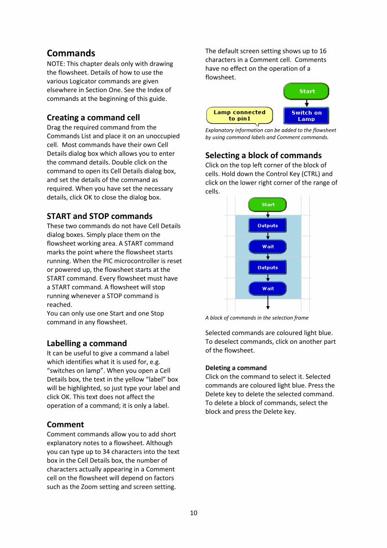
Labelling a command It can be useful to give a command a label
which identifies what it is used for, e.g.
“switches on lamp”. When you open a Cell
Details box, the text in the yellow “label” box
will be highlighted, so just type your label and
click OK. This text does not affect the
operation of a command; it is only a label.
Comment Comment commands allow you to add short
explanatory notes to a flowsheet. Although
you can type up to 34 characters into the text
box in the Cell Details box, the number of
characters actually appearing in a Comment
cell on the flowsheet will depend on factors
such as the Zoom setting and screen setting.
The default screen setting shows up to 16
characters in a Comment cell. Comments
have no effect on the operation of a
flowsheet.
Explanatory information can be added to the flowsheet
by using command labels and Comment commands.
Selecting a block of commands Click on the top left corner of the block of
cells. Hold down the Control Key (CTRL) and
click on the lower right corner of the range of
cells.
A block of commands in the selection frame
Selected commands are coloured light blue.
To deselect commands, click on another part
of the flowsheet.
Deleting a command
Click on the command to select it. Selected
commands are coloured light blue. Press the
Delete key to delete the selected command.
To delete a block of commands, select the
block and press the Delete key.

11
Moving commands To move a single command or a block of
commands, select the area and drag it to its
new position.
Cutting, Copying and Pasting Use the Cut, Copy and Paste options from the
Edit menu to cut or copy selected commands
or blocks of commands and paste them either
into another part of the same flowsheet or
into a different flowsheet. Alternatively, you
can copy commands or blocks of commands
within a flowsheet by first selecting them and
then holding down the Ctrl key as you drag
them to their new position. Remember that
copied commands will retain their existing cell
details.
Flowsheet working area
Cells are arranged in rows and columns. Each
flowsheet has 22 columns and 25 rows. The
default screen shows just 12 columns and 12
rows. Use the View>Zoom menu if you want
to change the number of cells visible on the
screen.
Map The Map option allows you to view the whole
of the flowsheet at once. The red square
marks the area currently displayed on the
screen.
Routes Routes can be drawn through the middle of a
cell, or in either one of the two rails between
cells. Routes must be drawn in the direction
that you want flow to take when the
flowsheet runs.
Drawing Lines
Click on the Line Drawing icon on the
toolbar to select drawing mode.
The mouse cursor changes to a pen icon.
Click at a command cell where the line should
start. Now move the pointer along the route
you wish to draw. A dotted line will show
where the route will be drawn. At a corner
click again and continue moving the pointer
until you reach the end of the desired route.
Routes can be drawn through cells or between rails.
Click to complete the route, then Right Click
to end drawing mode.
Drawing mode can also be deselected
by clicking the arrow icon.
Drawing mode can also be selected by right
clicking a command and choosing Start Line
from the submenu.
Lines can only be drawn vertically or
horizontally. Always draw the line in the
direction of the flow, as indicated by the
arrows.
Hot tip
By holding down the Control key, the arrow
keys can also be used to draw lines.
Deleting routes Click at the beginning of the route to be
deleted, and press the Delete key. When you
draw a new route from a command, the
existing route from the command will
automatically be deleted. To delete a route
without deleting the command in which it
starts: first click on the command to select it.
Then hold down the Ctrl key as you press the
Delete key.

12
How to test run a flowsheet Before you download a flowsheet to a PIC
microcontroller, it is useful to be able to check
that it works as you intend it to. Logicator has
a number of features that allow you to test
run the flowsheet in the software.
1. The Digital Panel As a flowsheet runs, the Digital Panel shows
the changing state of outputs, motors and
inputs as they would be if the flowsheet had
been downloaded to a PIC microcontroller.
To display the Digital Panel, select the
View>Digital Panel menu. Alternatively, click
the toolbar icon shown below.
Digital Panel and its toolbar icon
2. Simulating digital inputs The function keys on the computer keyboard
are used to simulate inputs from digital
sensors while a flowsheet is running.
Function keys F2 to F9 will simulate digital
sensors connected to inputs 0 to 7 on a PIC
microcontroller. Key F2 simulates input 0; key
F9 simulates input 7.
Pressing the function key is equivalent to the
sensor being “on” (1). When the key is not
pressed, it is equivalent to the sensor being
“off” (0).
Clicking on the corresponding input or output
on the digital panel will also have the same
effect.
3. Simulating analogue inputs The Analogue Panel allows you to simulate
the changing reading from analogue sensors
while a flowsheet is running. Identify the
sensor (A0 to A3) which you wish to simulate,
and use the slider in the panel to vary the
simulated reading from 0 to 255.
To display the Analogue Panel, select the
View>Analogue Panel menu. Alternatively,
click the toolbar icon shown below.
Analogue Panel and its toolbar icon
4. Run and Stop To test run a flowsheet, either click
the green Run icon or click the
Simulate >Run menu item.
To stop a flowsheet running, either
click the Stop icon or the
Simulate>Stop menu item.
As the flowsheet runs, the flow of control is
highlighted so that you can follow it. If you
want to slow down the speed at which flow is
highlighted, select the Options>Set Simulation
Run Speed... menu, and use the dialog box to
adjust the speed.
5. Variables and EEPROM display
windows If your flowsheet uses variables, it is useful to
display the Variables window when you test
run it. The changing values of any of the
variables A to H that are used in the flowsheet
will be displayed as the flowsheet runs.
The Variables window and the EEPROM window
The EEPROM display window shows the value
in each of the 16 addresses, when the
flowsheet uses the READ and WRITE
commands.
13
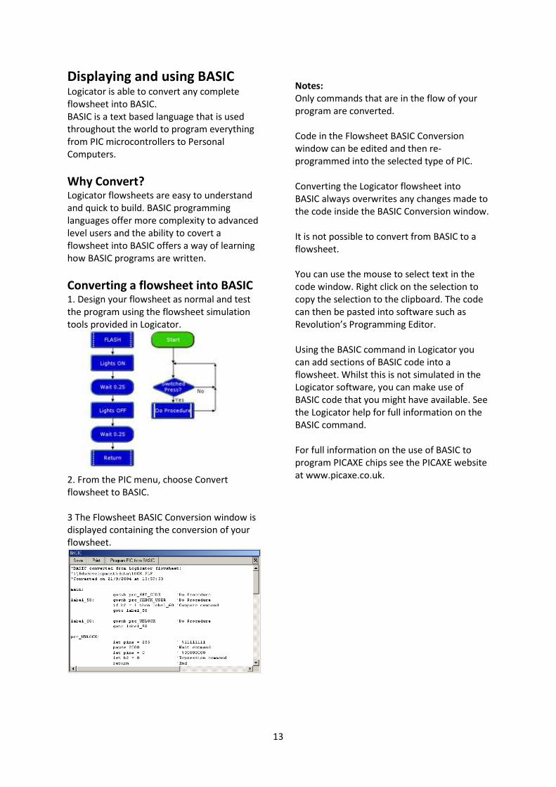
Displaying and using BASIC Logicator is able to convert any complete
flowsheet into BASIC.
BASIC is a text based language that is used
throughout the world to program everything
from PIC microcontrollers to Personal
Computers.
Why Convert? Logicator flowsheets are easy to understand
and quick to build. BASIC programming
languages offer more complexity to advanced
level users and the ability to covert a
flowsheet into BASIC offers a way of learning
how BASIC programs are written.
Converting a flowsheet into BASIC 1. Design your flowsheet as normal and test
the program using the flowsheet simulation
tools provided in Logicator.
2. From the PIC menu, choose Convert
flowsheet to BASIC.
3 The Flowsheet BASIC Conversion window is
displayed containing the conversion of your
flowsheet.
Notes:
Only commands that are in the flow of your
program are converted.
Code in the Flowsheet BASIC Conversion
window can be edited and then re-
programmed into the selected type of PIC.
Converting the Logicator flowsheet into
BASIC always overwrites any changes made to
the code inside the BASIC Conversion window.
It is not possible to convert from BASIC to a
flowsheet.
You can use the mouse to select text in the
code window. Right click on the selection to
copy the selection to the clipboard. The code
can then be pasted into software such as
Revolution’s Programming Editor.
Using the BASIC command in Logicator you
can add sections of BASIC code into a
flowsheet. Whilst this is not simulated in the
Logicator software, you can make use of
BASIC code that you might have available. See
the Logicator help for full information on the
BASIC command.
For full information on the use of BASIC to
program PICAXE chips see the PICAXE website
at www.picaxe.co.uk.
14
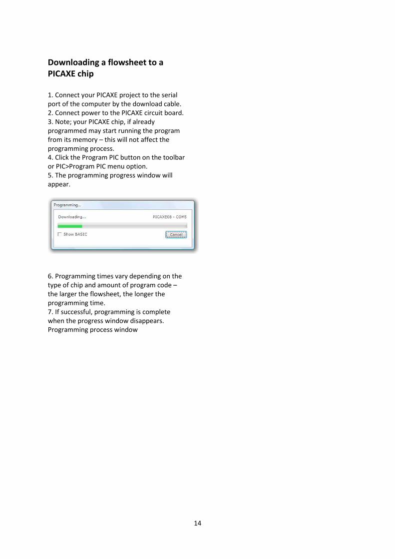
Downloading a flowsheet to a
PICAXE chip
1. Connect your PICAXE project to the serial
port of the computer by the download cable.
2. Connect power to the PICAXE circuit board.
3. Note; your PICAXE chip, if already
programmed may start running the program
from its memory – this will not affect the
programming process.
4. Click the Program PIC button on the toolbar
or PIC>Program PIC menu option.
5. The programming progress window will
appear.
6. Programming times vary depending on the
type of chip and amount of program code –
the larger the flowsheet, the longer the
programming time.
7. If successful, programming is complete
when the progress window disappears.
Programming process window

15
2. Outputs
Outputs command
We can use an Outputs command to switch
on or off any output devices that are
connected to the outputs of a PIC
microcontroller.
The “Output Pattern” line of its Cell Details
box (below) shows the number of outputs
available for use.
Outputs command Cell Details box
Each one of the digits in the Output Port
represents one of the outputs on the PIC
microcontroller. You can click each digit to set
it to switch an output device on or off.
This means: switch this output on.
This means: switch this output off.
This means: ignore this output,
i.e. leave it in the state in which it was
set by the previous Outputs command.
Wait command
A Wait command makes a running flowsheet
pause for the number of seconds specified
before the next command is carried out. You
can use it to keep output devices switched on
or off for a set time. Use its Cell Details box to
enter a number of seconds (Max 65s. Min
0.001s) or a Variable.
Example
A PIC microcontroller has 3 LEDs connected to
outputs 0, 1 and 2. The flowsheet shown top
right will switch them progressively on and off
in a timed sequence. The sequence will begin
as soon as the chip is powered and will stop at
the STOP command - so it will do the
sequence just once.
7 6 5 4 3 2 1 0
0 0 0 0 0 0 0 1
7 6 5 4 3 2 1 0
0 0 0 0 0 0 1 –
7 6 5 4 3 2 1 0
0 0 0 0 0 1 - -
7 6 5 4 3 2 1 0
0 0 0 0 0 0 0 0
The flowchart shown left
will continue to repeat
the sequence until
power to the chip is
switched off. Notice that
another Wait command
has been added to the
repeating sequence. The
PIC microcontroller
operates so quickly that,
without Wait
commands, the LEDs
would switch on and off
so quickly that you
would not see it
happening.
16
Out Command
When flow passes through an Out command,
the output port is set to the binary value of
the number entered in the command.
If you are familiar with the binary system then
the Out command is a convenient way of
switching combinations of outputs on or off.
In the table above the ‘bits’ can be switched
on by sending the selection value of the bit.,
e.g. ‘Out 4’, which will turn on an LED at bit 2.
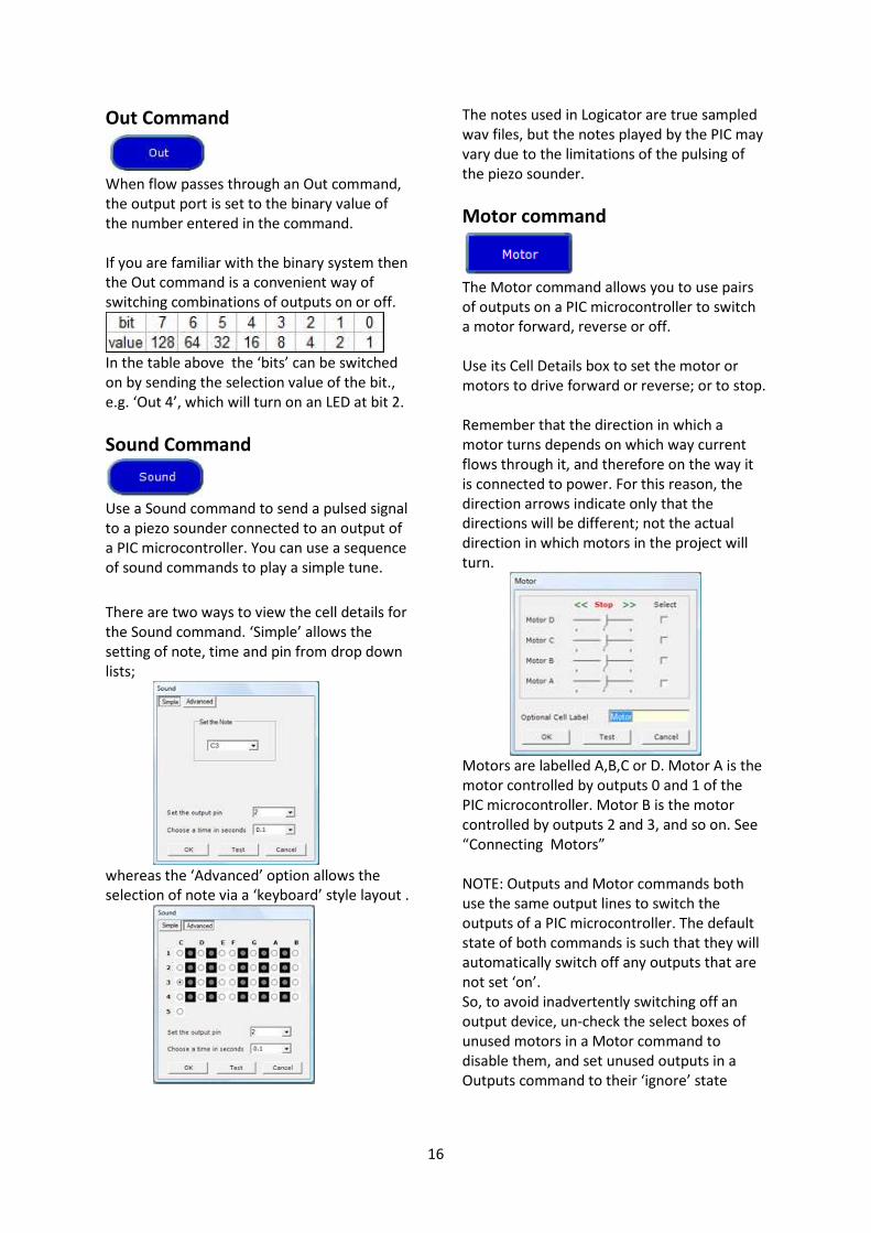
Sound Command
Use a Sound command to send a pulsed signal
to a piezo sounder connected to an output of
a PIC microcontroller. You can use a sequence
of sound commands to play a simple tune.
There are two ways to view the cell details for
the Sound command. ‘Simple’ allows the
setting of note, time and pin from drop down
lists;
whereas the ‘Advanced’ option allows the
selection of note via a ‘keyboard’ style layout .
The notes used in Logicator are true sampled
wav files, but the notes played by the PIC may
vary due to the limitations of the pulsing of
the piezo sounder.
Motor command
The Motor command allows you to use pairs
of outputs on a PIC microcontroller to switch
a motor forward, reverse or off.
Use its Cell Details box to set the motor or
motors to drive forward or reverse; or to stop.
Remember that the direction in which a
motor turns depends on which way current
flows through it, and therefore on the way it
is connected to power. For this reason, the
direction arrows indicate only that the
directions will be different; not the actual
direction in which motors in the project will
turn.
Motors are labelled A,B,C or D. Motor A is the
motor controlled by outputs 0 and 1 of the
PIC microcontroller. Motor B is the motor
controlled by outputs 2 and 3, and so on. See
“Connecting Motors”
NOTE: Outputs and Motor commands both
use the same output lines to switch the
outputs of a PIC microcontroller. The default
state of both commands is such that they will
automatically switch off any outputs that are
not set ‘on’.
So, to avoid inadvertently switching off an
output device, un-check the select boxes of
unused motors in a Motor command to
disable them, and set unused outputs in a
Outputs command to their ‘ignore’ state

17
Example
A steerable buggy is usually driven by two
motors, one powering each driving wheel
with a free-running jockey wheel to keep it
stable. The flowsheet below shows how a
sequence of Motor commands can be used to
drive a buggy which has one motor connected
to outputs 0 and 1 (motor A) and the other
motor connected to outputs 2 and 3 (motor
B).
The Motor commands have been given labels to show
what they do. The table beside each one shows how its
Cell Details have been set.
Sleep command
This command puts the PIC microcontroller
into low power mode for a specified number
of seconds.
This command can be used to save battery
power in your project. All output devices will
be left in their current condition, but signals
from input devices will not be responded to
while the chip is in sleep mode.
The Cell Details box is used to set the number
of seconds of sleep mode required (this is in
the form of number of multiples of 2.3
seconds). For example, a setting of 10 will
sleep for 23 seconds.
Note that Sleep times are not as accurate as
Wait times.
SerOut Command
This command allows output information to
be sent from the PIC microcontroller to a
device such as a serial printer, a serial LCD
screen or another PIC which is connected to
an output of a PIC microcontroller.
The first box is used to select the output pin
on the PIC microcontroller to send the data
through.
In the Data box either type in the ASCII text
you wish to send or raw data.
If sending raw data codes the ASCII box must
be unchecked.
ASCII codes are useful for sending commands
to LCD screens e.g. clearing the display.
Details of these control codes can normally be
found with the instructions for the particular
devices.

18
You can send a series of text characters e.g.
“Hello” or a series of ASCII codes e.g. “254,1”.
In the latter case, ASCII codes must be
separated by a comma.
If you wish to send the value held in a
variable, type in the variable name in square
brackets e.g. “[B]”. Note you must use capital
letters for the variable.
The last item to set is the serial mode. Set the
mode to that specified by the device you are
sending data to.
Example
The flowsheet shown below will display the
word “Hello” on an LCD screen connected to
output pin 2 of a PIC microcontroller.
A sequence to display the word ‘Hello’
Sertxd Command The sertxd command is similar to the serout
command, but acts via the serial
output pin rather than a general output pin.
This allows data to be sent back to
the computer via the programming cable. This
can be useful whilst debugging.
See the PicAxe Manual for more information
Servo Command Servos, as commonly found in radio control
toys, are a very accurate motor/gearbox
assembly that can be
repeatedly moved to the
same position due to their
internal position sensor. Generally servos
require a pulse of 0.75 to 2.25ms every 20ms,
and this pulse must be constantly repeated
every 20ms. Once the pulse is lost the servo
will loose its position.
The Servo command starts a pin pulsing high
for length of time pulse (x0.01 ms) every
20ms.
This command is different to all other
commands in that the pulsing mode continues
until another servo command or outputs
command. Outputs commands stop the
pulsing immediately. Servo commands adjust
the pulse length to the new pulse value,
hence moving the servo.
The cell details for the servo command have
two settings; the output pin that the servo
motor is connected to and the pulse time.
The pulse time can be a value held in a
Variable. Note that the value for the pulse
time MUST be in the range 75 to 225. The
servo motor may malfunction if the pulse is
outside of this range.
Servo command cell details
Example
The flowsheet below will move a servo motor
attached to output 0 from one extent of its
travel to the other, repeating continually.
Using the Servo command

19
PulseOut Command
The PulseOut command generates a pulse
through the chosen output. If the output is
initially off, the pulse will be on, and vice
versa.
There are two items to set in the cell details
box for the PulseOut command below; the
output pin to send the pulse through, and the
length of time that the pulse should operate
for.
The time is in 10ms intervals, but for easier
reading, the text area in the command
converts this to milliseconds as the time is
entered into the command. PulseOut times
must be in the range 1 – 65535.
Note that Logicator cannot simulate the
action of the PulseOut command.
Example
The flowsheet below sends a pulse of
15ms out of output pin 4 every half second.
Using the PulseOut command
PlayTune command
The following PICAXE chips can play musical
tones: 08M, 14M, 20M, 28X1, 40X1. These
have 4 pre-programmed internal tunes, which
can be output via the PlayTune command.
As these tunes are included within the PICAXE
bootstrap code, they use very little program
memory.
The cell details require that the number of the
tune is set and if you wish the outputs to flash
in time to the tune.
The Tunes are:
0 - Happy Birthday
1 - Jingle Bells
2 - Silent Night
3 - Rudolf the Red Nosed Reindeer
The Flash modes are:
0 - No outputs
1 - Output 0 flashes on and off
2 - Output 4 flashes on and off
3 - Output 0 and 4 flash alternately
The following example will play Happy
Birthday while flashing output 4.
Logicator cannot accurately simulate the
flashing actions of the PlayTune command.
It is possible within the Programming Editor
software available from Revolution Education,
to program your own tune into a these types
of PICAXE chip.
20
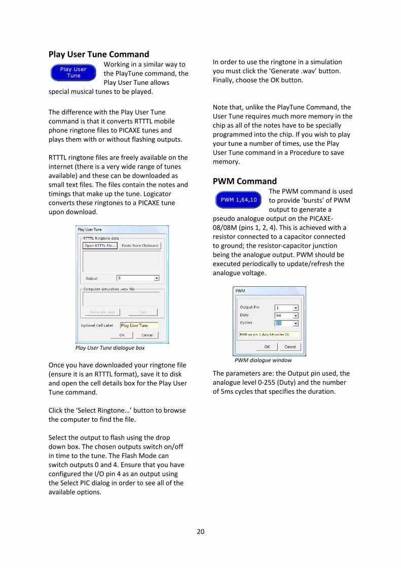
Play User Tune Command Working in a similar way to
the PlayTune command, the
Play User Tune allows
special musical tunes to be played.
The difference with the Play User Tune
command is that it converts RTTTL mobile
phone ringtone files to PICAXE tunes and
plays them with or without flashing outputs.
RTTTL ringtone files are freely available on the
internet (there is a very wide range of tunes
available) and these can be downloaded as
small text files. The files contain the notes and
timings that make up the tune. Logicator
converts these ringtones to a PICAXE tune
upon download.
Play User Tune dialogue box
Once you have downloaded your ringtone file
(ensure it is an RTTTL format), save it to disk
and open the cell details box for the Play User
Tune command.
Click the ‘Select Ringtone…’ button to browse
the computer to find the file.
Select the output to flash using the drop
down box. The chosen outputs switch on/off
in time to the tune. The Flash Mode can
switch outputs 0 and 4. Ensure that you have
configured the I/O pin 4 as an output using
the Select PIC dialog in order to see all of the
available options.
In order to use the ringtone in a simulation
you must click the ‘Generate .wav’ button.
Finally, choose the OK button.
Note that, unlike the PlayTune Command, the
User Tune requires much more memory in the
chip as all of the notes have to be specially
programmed into the chip. If you wish to play
your tune a number of times, use the Play
User Tune command in a Procedure to save
memory.
PWM Command The PWM command is used
to provide ‘bursts’ of PWM
output to generate a
pseudo analogue output on the PICAXE-
08/08M (pins 1, 2, 4). This is achieved with a
resistor connected to a capacitor connected
to ground; the resistor-capacitor junction
being the analogue output. PWM should be
executed periodically to update/refresh the
analogue voltage.
PWM dialogue window
The parameters are: the Output pin used, the
analogue level 0-255 (Duty) and the number
of 5ms cycles that specifies the duration.

21
3. Inputs Input devices such as switches and sensors
send information from the outside world into
the control system. Output devices are
switched on or off in response to the
information provided by input devices.
Example
A buggy is often fitted with micro-switches so
that if it approaches an obstacle, a
microswitch will be pressed.
The information that the switch has been
pressed can be used in the system to switch
off the motors driving the buggy, and start a
sequence of movements to move around the
obstacle.
A microswitch is a digital sensor. It has only
two states - “on” (or “closed”) and “off” (or
“open”).
These states are often labelled by the digits 1
and 0, which is why the sensors are called
digital sensors.
Example
A controlled hot water system includes a
temperature sensor which constantly
monitors the water temperature.
The water heater is switched on and off in
response to the information provided by the
sensor. If the water temperature falls below a
set level, the heater is switched on until it
reaches that level again. Then the heater is
switched off.
A temperature sensor is an analogue sensor.
It provides a reading which changes in line
with the changing level of whatever it is
sensing.
22
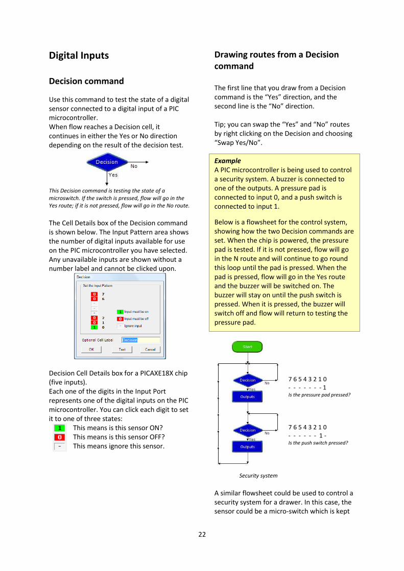
Digital Inputs
Decision command
Use this command to test the state of a digital
sensor connected to a digital input of a PIC
microcontroller.
When flow reaches a Decision cell, it
continues in either the Yes or No direction
depending on the result of the decision test.
This Decision command is testing the state of a
microswitch. If the switch is pressed, flow will go in the
Yes route; if it is not pressed, flow will go in the No route.
The Cell Details box of the Decision command
is shown below. The Input Pattern area shows
the number of digital inputs available for use
on the PIC microcontroller you have selected.
Any unavailable inputs are shown without a
number label and cannot be clicked upon.
Decision Cell Details box for a PICAXE18X chip
(five inputs).
Each one of the digits in the Input Port
represents one of the digital inputs on the PIC
microcontroller. You can click each digit to set
it to one of three states:
This means is this sensor ON?
This means is this sensor OFF?
This means ignore this sensor.
Drawing routes from a Decision
command
The first line that you draw from a Decision
command is the “Yes” direction, and the
second line is the “No” direction.
Tip; you can swap the “Yes” and “No” routes
by right clicking on the Decision and choosing
“Swap Yes/No”.
Example
A PIC microcontroller is being used to control
a security system. A buzzer is connected to
one of the outputs. A pressure pad is
connected to input 0, and a push switch is
connected to input 1.
Below is a flowsheet for the control system,
showing how the two Decision commands are
set. When the chip is powered, the pressure
pad is tested. If it is not pressed, flow will go
in the N route and will continue to go round
this loop until the pad is pressed. When the
pad is pressed, flow will go in the Yes route
and the buzzer will be switched on. The
buzzer will stay on until the push switch is
pressed. When it is pressed, the buzzer will
switch off and flow will return to testing the
pressure pad.
7 6 5 4 3 2 1 0
- - - - - - - 1 Is the pressure pad pressed?
7 6 5 4 3 2 1 0
- - - - - - 1 - Is the push switch pressed?
Security system
A similar flowsheet could be used to control a
security system for a drawer. In this case, the
sensor could be a micro-switch which is kept

23
closed (on) as long as the drawer is shut. If
someone opens the drawer, the microswitch
will be open (off).
The flowsheets below shows two different
ways of using a Decision command to test the
micro-switch in this system.
7 6 5 4 3 2 1 0
- - - - - - - 0 Is the sensor off? (drawer open?)
7 6 5 4 3 2 1 0
- - - - - - - 1 Is the sensor on? (drawer shut?)
Notice that the direction of flow depends on how the
command is set.
Example
Home security systems often have a number
of sensors in different parts of the house. If
any one of them is activated, the alarm is
switched on. The flowsheet below shows a
security system which has three sensors and a
reset switch.
Security system with three sensors (OR function).
Two of the sensors are the magnetic type for
windows which have the magnet fixed to the
window frame and the reed switch fixed to
the window. As long as the window is shut,
the magnet keeps the reed switch contacts
closed (“sensor on”). When the window is
opened and the magnet is moved away from
the switch, the contacts are open (“sensor
off”). Therefore, the two Decision commands
have been set to go in the Yes route if the
sensor is off (0).
The system shown is an OR function.
Some security systems have two separate
reset switches arranged in an AND function so
that the system is reset only if both switches
are pressed together. The flowsheet below
shows how you can set a Decision command
to test two switches in this way.
7 6 5 4 3 2 1 0
- - - - - 1 1 -
Decision command set to check if two switches are
pressed at the same time (AND function).
Example
In the flowsheet shown below, the output is
switched on when a push switch is pressed.
When you stop pressing the switch the output
switches off. In other words: IF the input is on,
THEN switch the output on, ELSE switch the
output off.
“Normally open” switch effect.
This is the equivalent of a simple electrical
circuit containing a normally open push switch
and an output device.
The difference is that you can change the way
the system works in software, by simply
changing over the Yes and No on the Decision
command :

24
“Normally closed” switch effect.
Example
A mono-stable device has only one stable
state. It changes state when it is triggered by
an input, and stays in that state for a certain
time. It then goes back to its original state.
The flowsheet below shows how this function
can be produced in Logicator.
“Mono-stable” function.
Example
A bi-stable device has two stable states. It
changes state when it is triggered (set) by an
input, and stays in that state until it is
triggered (reset) by a second input. It then
goes back to its original state. The flowsheet
below shows how this function can be
produced in Logicator.
Bi-stable” function using
two switches for set and
reset.
The flowsheet below shows how you can use
just one switch for both set and reset. In this
case the Decision commands are used in
pairs.
The first one checks to see if the switch is
pressed, and the second one checks for it to
be un-pressed before the output is switched.
The program is processed so fast that, if you
didn’t include this feature, it would switch the
output and start checking the switch again
while you were still pressing it for the first
time.
“Bi-stable” function using one switch for both set and reset
25
Interrupt
An Interrupt instantly
captures the flow of control
whenever a preset digital input condition
occurs to trigger it e.g. when a switch is
pressed.
When the interrupt is triggered flow jumps
immediately to the Interrupt command and
then carries out any commands which follow
until it reaches a Return command. It then
returns to the point which it was at when the
Interrupt occurred.
In order to use an Interrupt, the PIC must be
told to look for the input condition. This is
done through the Interrupt Setup command.
There are two options in the command –
Enable or Disable.
To prevent the Interrupt
retriggering itself, the
Interrupt is automatically
disabled once it is triggered. To re-enable it
another Interrupt Setup command is required.
Example
A PIC microcontroller running a continuous
loop flashing lights needs to be able to react
to a button press and play a warning sound.
The Interrupt is used to capture the flow and
play a sound. The interrupt is then enabled
once again before returning to the point at
which it left the main flow.
Note that the Interrupt MUST have an
associated Return command and will not be
triggered again until this Return command has
been reached. There is no limit to the number
of commands between the Interrupt and the
Return.
Only one Interrupt can be used per flowsheet.
SerIn Command
The SerIn command is used
to receive serial data into an
input pin of the
microcontroller. It cannot be used with the
serial download input pin, which is reserved
for program downloads only.
The cell details box for the SerIn command
has three boxes to set.
SerIn command cell details box
The input pin is the input on the PICAXE that
the data is to be received through. The
Variable option is a variable location that the
data is stored into once it is received.
Lastly, the mode option specifies the baud
rateand polarity of the signal. When using
simple resistor interface, use N (inverted)
signals. When using a MAX232 type interface
use T (true) signals. The protocol is fixed at
N,8,1 (no parity, 8 data bits, 1 stop bit).
For best results do not use a baud rate higher
that 2400 on 4Mhz chips.
The SerIn command forces the PICAXE chip to
wait until serial data is received through the
chosen input. This data is stored in the chosen
variable.
26
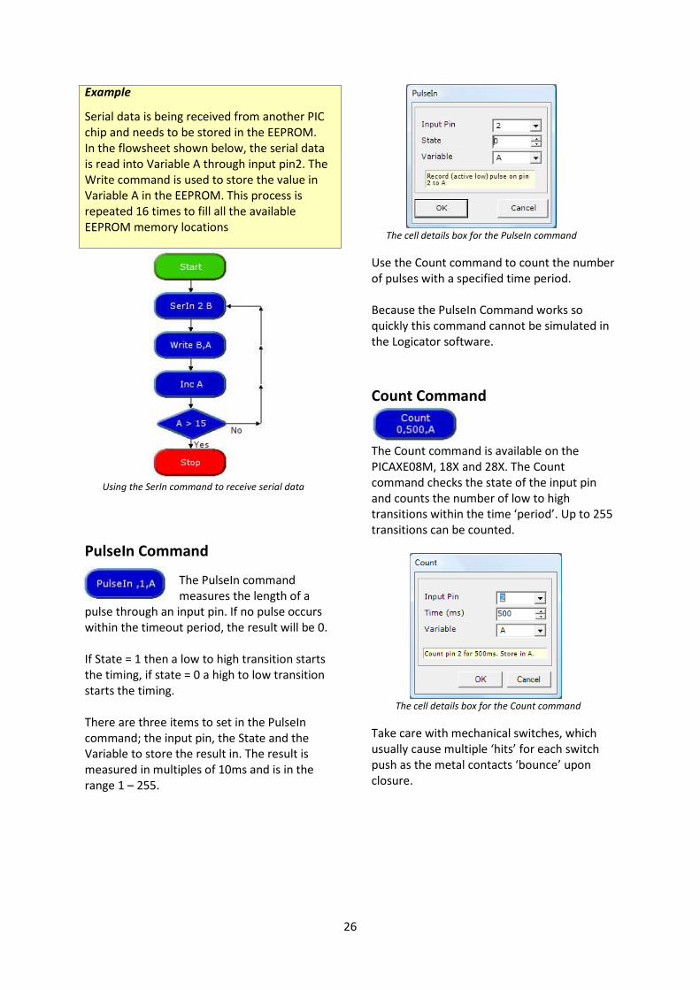
Example
Serial data is being received from another PIC
chip and needs to be stored in the EEPROM.
In the flowsheet shown below, the serial data
is read into Variable A through input pin2. The
Write command is used to store the value in
Variable A in the EEPROM. This process is
repeated 16 times to fill all the available
EEPROM memory locations
Using the SerIn command to receive serial data
PulseIn Command
The PulseIn command
measures the length of a
pulse through an input pin. If no pulse occurs
within the timeout period, the result will be 0.
If State = 1 then a low to high transition starts
the timing, if state = 0 a high to low transition
starts the timing.
There are three items to set in the PulseIn
command; the input pin, the State and the
Variable to store the result in. The result is
measured in multiples of 10ms and is in the
range 1 – 255.
The cell details box for the PulseIn command
Use the Count command to count the number
of pulses with a specified time period.
Because the PulseIn Command works so
quickly this command cannot be simulated in
the Logicator software.
Count Command
The Count command is available on the
PICAXE08M, 18X and 28X. The Count
command checks the state of the input pin
and counts the number of low to high
transitions within the time ‘period’. Up to 255
transitions can be counted.
The cell details box for the Count command
Take care with mechanical switches, which
usually cause multiple ‘hits’ for each switch
push as the metal contacts ‘bounce’ upon
closure.

27
Analogue Inputs
ReadADC
This command is used to
read an analogue value from
an analogue channel and
assign the value to a variable. It is equivalent
to using an Expression to set a variable
equivalent to an analogue channel, as in the
expression: A = A1.
Debug
To read analogue values ‘live’
from a PIC chip we can use
the Debug command in a
loop like in the flowchart below.
We then open the Debug window from the
Menu PIC > Debug. When we download the
above flowsheet into the PIC chip we need to
keep the lead connected to the PIC chip in
order for the analogue values to be read and
displayed in the Debug window.
ReadTemp
This command is used to
read an analogue value from
a D18B20 temperature sensor.
Compare command
This command can be used
to check the reading from an
analogue sensor connected to an analogue
input of a PIC microcontroller. The most
common use of an analogue sensor in a
control system is to switch output devices on
or off when the reading from the sensor
reaches a particular level. This level is
sometimes called the “threshold”.
When flow reaches a Compare cell, the
software checks the current reading from the
specified sensor, and compares it with the
threshold that you have set. Flow will
continue in either the “Yes” or “No” direction
depending on the result of the comparison.
The Cell Details box of the Compare command
is shown below.
Cell Details box of the Compare command
1. Use box one to select the sensor that you
want the command to check.
Analogue sensors are labelled A0 to A3
according to which pin on the chip they are
connected to. Type in the number of the
sensor you want the command to check, or
select it from the drop-down box.
2. Use boxes two and three to complete the
comparison. The drop-down list in box two
contains a list of operators such as “greater

28
than” (>), “less than” (<), and “equals” (=).
Select the one that you require. NOTE: It is
usually better to use an operator such as
“greater than or equals” (>=) instead of
“equals”, because analogue sensor readings
can fluctuate rapidly, and you may find that
the checking of the sensor reading never
actually coincides with the exact threshold
level.
3. Use box three to set the threshold level.
Type in a number between 0 and 255, or
select it from the drop-down list.
Example one
A PIC microcontroller is being used to control
a lamp. A light sensor is connected to
analogue input 0. The system will switch on
the lamp automatically in dark conditions.
Below is a flowsheet for the system.
System to switch on a lamp automatically in dark
conditions.
The Compare command checks the reading
from the light sensor. If the reading is less
than or equal to 50, flow will go to the Yes
route and switch on the lamp; if the reading is
greater than 50, flow will go in the No route
and switch off the lamp. The system could be
extended as shown below. This system
controls three separate lamps, which it
switches on one by one as darkness falls.
System to switch on three lamps in response to changing
light levels.
Example
A PIC microcontroller is used to make a light
meter for use by cricket or tennis umpires to
decide when to abandon play because of bad
light. A light sensor is connected to analogue
input 0. An LED is connected to each one of
the eight outputs. In bright sunlight, all the
LEDs will be lit. As the light level falls, the LEDs
will switch off one by one.
Below is the flowsheet for the system.
Notice the use of the Out command to switch
on combinations of outputs.
Light meter system
29
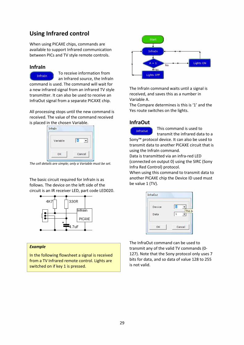
Using Infrared control
When using PICAXE chips, commands are
available to support Infrared communication
between PICs and TV style remote controls.
InfraIn To receive information from
an Infrared source, the InfraIn
command is used. The command will wait for
a new infrared signal from an infrared TV style
transmitter. It can also be used to receive an
InfraOut signal from a separate PICAXE chip.
All processing stops until the new command is
received. The value of the command received
is placed in the chosen Variable.
The cell details are simple; only a Variable must be set.
The basic circuit required for InfraIn is as
follows. The device on the left side of the
circuit is an IR receiver LED, part code LED020.
Example
In the following flowsheet a signal is received
from a TV Infrared remote control. Lights are
switched on if key 1 is pressed.
The InfraIn command waits until a signal is
received, and saves this as a number in
Variable A.
The Compare determines is this is ‘1’ and the
Yes route switches on the lights.
InfraOut This command is used to
transmit the infrared data to a
Sony™ protocol device. It can also be used to
transmit data to another PICAXE circuit that is
using the InfraIn command.
Data is transmitted via an infra-red LED
(connected on output 0) using the SIRC (Sony
Infra Red Control) protocol.
When using this command to transmit data to
another PICAXE chip the Device ID used must
be value 1 (TV).
The InfraOut command can be used to
transmit any of the valid TV commands (0-
127). Note that the Sony protocol only uses 7
bits for data, and so data of value 128 to 255
is not valid.

30
Using ultrasonic measurement
Ultra The Ultra command is use to
detect an object using the
SRF005 ultrasonic sensor.
When the output and input pins area assigned
to the sensor position the command returns
the distance to an object (cm) and assigns this
value to a variable.

31
4. Procedures
Logicator software provides a clear, step-by-
step method of building a complex control
system, by creating a number of linked
subsystems called “procedures”. Note that
'Return' was previously known as
'End' and so now use 'Return' instead of 'End'.
How to build a procedure
Use a Procedure command to begin the
procedure. Drag the command onto the
flowsheet and place it separately from the
START command as shown below. Double
click on the command to open its Cell Details
box. Type in any appropriate name, and click
OK. The software automatically puts the name
into capitals.
Placing the Procedure command
Use other commands as normal to create the
procedure.
Place a RETURN command at the end of the
procedure as shown in the flowsheet below.
This command does not have a Cell Details
box; simply place it on the flowsheet.
This procedure, called FLASH will switch on selected
lamps for 3 seconds and then switch them off
When you have created a procedure, you can
test run it. Click on the Procedure command
to select it, and click System>Run
How to use a procedure
Once you have built a procedure, you can call
it into use whenever you like in the flowsheet
by using the Do Procedure command, as
shown below.
The Do Procedure command calls the procedure into use.
Drag a Do Procedure command onto the
flowsheet. Place it at the point where you
want the procedure to be called into use.
Double click on the command to open its Cell
Details box. Type in the name of the
procedure or select it from the drop-down
list. Click OK.
Note that all the procedures that have been
built in a flowsheet are automatically listed in
the drop-down box. When flow reaches a Do
Procedure command, it jumps to the
Procedure command with the same name.
When the flow of control reaches a Return
command, the flow jumps back to the Do
Procedure command that called the
procedure. To test run the whole flowsheet,
click on the START command to highlight it,
and click System>Run
In the cell details box for the Do Procedure
command it is also possible to set the number
of times top run the Procedure. This will
simply repeat the Do Procedure for the set
number and then continue as normal.

32
Example
A PIC microcontroller is used to control a
system in a child’s toy which plays a tune
when it is hugged. A piezo transducer is
connected to an output pin, and a push switch
is used to sense when the toy is hugged. The
flowsheet for the system is shown below. The
tune is created as a procedure which can be
tested and edited separately from the main
routine.
Using a Procedure to play a tune after an input condition
is met
Example
The flowsheet shown below is a control
system for a sliding door. When a switch is
pressed, the door opens. It stays open for ten
seconds and then closes again. The system
uses limit switches to sense when the door is
fully open and fully closed. The motor is
halted in response to the feedback from these
microswitches.
Sliding door control system using procedures

33
Example
A keypad is a useful input device. This
example shows how the Logicator software
can be used to scan a keypad in a project in
which a three digit number has to be entered
to open a solenoid-operated lock.
Connect the keypad to a PIC microcontroller
using inputs and outputs as shown right.
The flowsheet below shows how the scanning
is done.
In this case, the code number uses a digit
from each one of the first three rows (e.g. 357
or 268). Each row is scanned in turn using a
procedure.
To begin with, the row is made “live” by
switching on the output to which it is
connected. Then a Decision command checks
for the appropriate key in that row to be
pressed, by testing for that input to be on.
When the correct key is pressed, flow passes
on to the next procedure.
A Flowsheet to scan the keypad
When all three digits have been entered
correctly, the solenoid is switched to unlock
the door.
Keypad connections

34
Designing systems with
procedures
Using procedures, you can design and test
systems either “top-down” or “bottom-up”.
Example
The ‘top-down’ approach
This approach begins with an overall view of
the system (the main routine), and then
creates each part of it separately as a
procedure. The following sequence shows
how it can be used to develop a control
system for a buggy which is fitted with micro-
switches that are pressed if the buggy comes
into contact with an obstacle.
When this happens, the buggy sounds an
alarm and moves round the obstacle.
1. The main routine is created as a series of
Do Procedure commands as shown right.
2. Then each part of the system is built as
a separate procedure as shown below.
Each procedure can be test run
independently.
Notice that the AVOID procedure uses the top-down approach, so the flowsheet is incomplete at this stage.
Main Routine

35
3. The AVOID procedure shown below has been built by using the
top-down approach. To clarify the avoiding procedure, each
movement is simply listed as a Do Procedure command. Then the
details required for the buggy to make each movement can be dealt
with separately as shown below.
This flowsheet illustrates the way in which procedures may be called from within other procedure definitions.

36
Example
The ‘bottom-up’ approach
This approach develops each part of the system separately as a procedure, and then writes the main
routine to link them. The following sequence shows how it can be used to develop a control system
for an animated clown’s head on which the eyes and nose light up and the hat rotates.
1. A separate procedure is built and tested for each one of the three elements, as shown below:
In this approach, the procedures are created first
2. A main routine is then written to call the procedures into use in the required sequence whenever
a switch is pressed.
The complete system
This flowsheet shows some of the advantages of using this approach. Once a procedure has been
created, it can be called into use as many times as you like within the flowsheet. Editing the
sequence is easy.
The Do Procedure commands can be moved around, deleted or copied to change the sequence as
required. Procedures can be cut, copied and pasted between flowsheets. Remember that copied
commands will retain their existing cell details.

37
5. Variables
In Logicator a variable is a single letter or a
keyword that can be given a value. The
variables that can be used are: any one of the
single letters A to H. This section explains how
they can be used for a variety of mainly
counting and timing purposes.
Counting
The Inc command Each time flow passes
through an Inc command, 1
is added to the value of the
selected variable (Inc is short for increment).
This is the same as using an Expression
command to make A = A + 1.
When you open the Cell Details box, simply
select which variable you want to use, and
click OK.
The flowsheet shown below shows how it can
be used to repeat a sequence three times.
Each time that flow goes round the loop, the
FLASH procedure is undertaken, and 1 is
added to the value of variable A.
A Compare is used to check the value of A.
When this value reaches 3, flow will go in the
Yes direction and stop the flowsheet.
Repeating a sequence three times
Cell Details box of the Compare command
1. Use box one to select the variable that you
want the command to check.
2. Use boxes two and three to complete the
comparison. The drop-down list in box two
contains a list of operators such as “greater
than” (>), “less than” (<), and “equals” (=).
Select the one that you require.
3. Use box three to set the number of times
the sequence will repeat. Type in a number
between 0 and 255, or select it from the
dropdown list.
Another use of the Inc command is to count
the number of times something happens – the
number of people passing through a gate or
turnstile for example. This is often done by
using a digital sensor such as a micro switch or
a reed switch placed so that the sensor is “on”
when a person passes. The flowsheet below
shows the three commands needed to do
this. Notice that two Decision commands are
used to check the switch. The first command
responds when the sensor is on. Then the
sensor is immediately checked again to see
that it is off before anything else happens.
This ensures a clean signal for the Inc
command to count.
Ensuring a clean signal from a digital sensor

38
You may well find that once it is downloaded
into the chip, the flowsheet runs so quickly
that even using the two Decision commands
does not give a clean count. If this is the case,
you should include a short Wait before the Inc
command, as shown in the flowsheet on the
right. This flowsheet is for a system to count
the number of people passing through a
turnstile and to display the number in binary
form, using LEDs connected to each one of
the eight outputs on a PIC microcontroller.
Example
A PIC microcontroller is used to control a
system for counting cars entering and leaving
a car park using two digital sensors. The
outputs of the system are a red lamp lighting
The flowsheet for the system is shown below.
When you run this flowsheet, display the
Variables window to see the value of A
change.
Flowsheet for making and displaying a count.
The DEC command
This system uses the Dec command which
works in a very similar way to the Inc command.
The difference is that when flow passes
through a Dec command, one is subtracted
from the selected variable.
Car Park Counting System

39
Example
A seven-segment display is a useful output
device for displaying counting and timing. The
flowsheet below is designed to control the
kind of supermarket delicatessen counter
system in which customers take a ticket and
then wait for their turn to be served when
their number is displayed. When the assistant
has served a customer, he or she presses a
switch to display the next number.
The main routine uses an Inc command to
increment (add one to) the value of the
variable A each time the assistant presses the
switch. The DISPLAY procedure makes an
efficient way of translating the current value
of A into an Outputs command which is set to
switch on the appropriate number of outputs
to display the number.
A similar approach could be used with an LCD
screen. In this case, the DISPLAY procedure
would use a series of SerOut commands as
shown below:
Part of an equivalent system that uses an LCD screen to
display numbers.
A “Now Serving....” display system.

40
Timing
To repeat a sequence for a period of time, the
Inc command can be used to count the
elapsed time. The flowsheet shown below
shows how it can be used to repeat a
sequence for 10 seconds.
Repeating a sequence for 10 seconds
A Compare is used to check the value of
Variable A. When this value reaches 10, flow
will go in the Yes direction and stop the
flowsheet. Since we know that the FLASH
Procedure will take 1 second to complete,
repeating this for 10 times will take 10
seconds.
Setting the value of a variable
The Expression command
The Expression command
is used to give a value to a
variable as a flowsheet
runs. The variable is given its value as flow
passes through the command. The following
example shows how it can be used.
Example
A container in a warehouse is designed to
hold ten packs of components. A system is
needed to indicate the changing contents of
the container as packs are removed. The next
flowsheet is designed to do this.
A digital sensor is used to indicate each time a
pack is removed (notice the use of two
Decision commands to ensure a clean count).
The number of packs in the container is
displayed as a binary count using 8 LEDs
connected to outputs of the PIC
microcontroller.
Counting Down
The Dec command counts down, so an
Expression command is used to set the value
of variable A to 10 at the start of the
countdown when the container is full. The
Expression command Cell Details box is shown
below. Use the first two boxes to enter the
expression A = 10.
Expression command : Setting the value of a variable

41
Mathematical expressions A value can also be given to a variable in the
form of a mathematical expression as shown
in the flowsheet below. This system counts
the number of times that two separate
switches are pressed, and displays the
combined total. Use all four boxes in the
Expression Cell Details box to enter the
39 expression C=A + B. NOTE: the third box in
the Expression Cell Details box contains a
range of mathematical operators.
Displaying a combined count
The IN command
The IN command sets the
value of a specified variable
to the current binary value
of the input port.
For example, if switches connected to inputs 0
and 1 are pressed, then the value of the
variable will be 3. The next flowsheet shows
how this can be used to make a simple
security system.
When switches connected to inputs 0 and 2
are pressed at the same time the binary value
of the input port equals 5 (4+1), flow from the
Decision command goes in the Yes direction
and a solenoid-operated lock is opened. If any
other combination of switches is pressed,
flow goes in the No direction.
Security system that responds to pressing two switches
The RND expression
Using the expression
command a Variable can be
given a random value
between 0 and 255. In the example shown
below, a set of display lights for a small
Christmas tree are connected to 8 outputs of
a PIC microcontroller. Every second the
display will change at random.
Using RND to create a random display of lights
Note that as with all microcontrollers and
computers, the generation of random
numbers is based on a set sequence.
Another way to create a
random value to a variable is
to use the Random command.

42
READ and WRITE
When a flowsheet run is started, all variable
values automatically reset to zero. So, when
the PIC microcontroller is reset or powered
up, all variable values are reset to zero.
If you want to retain variable values when the
PIC microcontroller is powered up or reset,
you can use the WRITE command to store
values in the chip’s EEPROM memory. The
READ command is used to retrieve the values
from the chip’s memory. The flowsheet below
right shows an example of how the
commands can be used. The following
information explains how this works.
The READ command takes the value which is
currently stored in a selected address (in this
case address 0), and puts it into the selected
variable (in this case variable A). Use the READ
command Cell Details box (below) to enter
the variable and the address from which the
value is to be read.
READ command Cell Details box
The PIC microcontroller’s EEPROM memory
has 16 separate addresses. Each one can store
a number between 0 and 255. The EEPROM
window displays the contents of the memory
when you test run a flowsheet.
EEPROM window
The OUT A command in the flowsheet
displays the current value of A using 8 LEDs
connected to outputs of the PIC
microcontroller.
The Inc A command increments (adds one to)
the value of A each time a switch is pressed.
The new value of A is immediately stored in
address 0 of the EEPROM memory by the
WRITE command. The Cell Details box of this
command is used in the same way as for the
READ command.
When the PIC microcontroller is powered
down, the value of A is stored in the chip’s
memory.
When the PIC microcontroller is powered up,
the first thing that happens is that the READ
A,0 command retrieves the value of A which
has been stored in address 0. The EEPROM
window gives an accurate simulation of the
way these commands work when the
flowsheet is downloaded.
Using READ and WRITE commands to store a count
This flowsheet shows how the Read and Write
commands are use to store the number of
times a switch is pressed.

43
Time
The PICAXE 28X1 chip has an internal clock
module. The Time On command starts the
clock cycle. The Time Off command will stop
the clock. The elapsed time will be measured
in seconds by the variable ‘Time’.
The flowsheet below will measure the elapsed
time until a button is pressed. The Time can
be viewed in the Time panel and in this case
its value is stored in the variable A.
LCD
This command can be used to
display a message on an LCD
screen attached to a PICAXE-
driven circuit board.
In the cell details window a message can be
written over two lines if required and an
output pin is assigned.
This command will be simulated if the
flowsheet is run from Simulate > Run.
A small window will pop up during the run to
display the LCD message. The window can be
enabled by choosing View > LCD panel
a simulated LCD screen
BASIC This command is used as an
extension to a flowchart.
PICAXE BASIC code can be
typed into the command cell window. When
program flow arrives at this command the
BASIC code within the command will be
interpreted as if it were a procedure.
RANDOM This command can be used to
generate a pseudo random
number and assign it to a variable.
The Random dialogue window
For greater randomness, use the command in
a loop terminated by a switch press.

44
Simulations
Logicator will support the use of simulations
of PIC circuits. These simulations are called
Soft Systems.
On the CD supplied with the software are a
number of simulations. Soft Systems are
accessed from the Simulate menu.
An example follows:
The Rudolf Soft System
A Helper screen can be opened from the
Simulation Help menu. This tells us which
PICAXE chip the circuit is simulating and how
the inputs and outputs are connected.
The Rudolf helper window
The simulation can be manipulated as though
it were a real circuit board:
� The battery terminal can be clicked to plug
and unplug the battery connections.
� The USB lead can be clicked to connect and
disconnect it.
� The inputs can be clicked to generate a
simulated input.
With this information, the student can now
program and test the simulation as thought it
was a real system.
This simulation is also available as a real
circuit board. In practice, students can work
on either the real circuit board or the
simulation with equal effect.
Further Soft Systems can be created using the
Soft Systems editor.

45