a deformation model to support a next generation ... · support a next generation. australian...
TRANSCRIPT

A Deformation Model to support a Next GenerationAustralian Geodetic Datum
Richard Stanaway, Surveying and Geospatial Engineering
CRCSI Project 1.02 – Next Generation Australian and New Zealand Datum
School of Civil and Environmental Engineering
CRCSI Project 1.02 – Next Generation Australian and New Zealand Datum
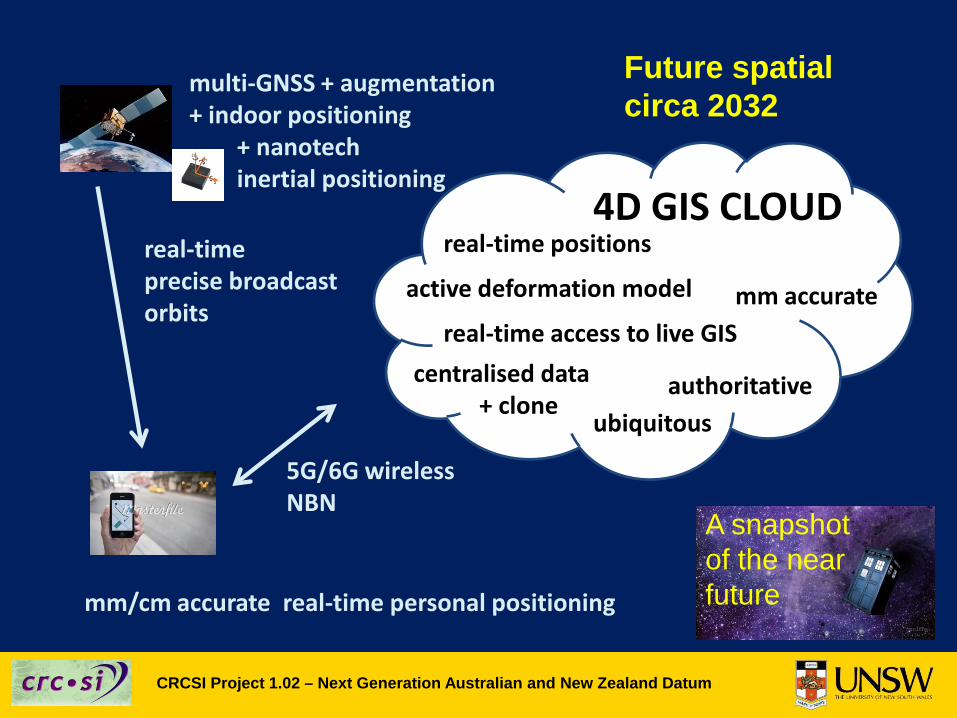
Future spatialcirca 2032
4D GIS CLOUDreal-time positions
centralised data+ clone
mm accurate
authoritativeubiquitous
real-time access to live GIS
mm/cm accurate real-time personal positioning
multi-GNSS + augmentation+ indoor positioning
+ nanotech inertial positioning
real-timeprecise broadcast orbits
5G/6G wirelessNBN
active deformation model
A snapshotof the near future
CRCSI Project 1.02 – Next Generation Australian and New Zealand Datum
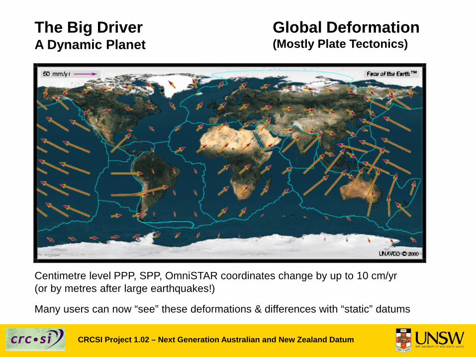
Global Deformation(Mostly Plate Tectonics)
Centimetre level PPP, SPP, OmniSTAR coordinates change by up to 10 cm/yr(or by metres after large earthquakes!)
Many users can now “see” these deformations & differences with “static” datums
The Big DriverA Dynamic Planet
CRCSI Project 1.02 – Next Generation Australian and New Zealand Datum
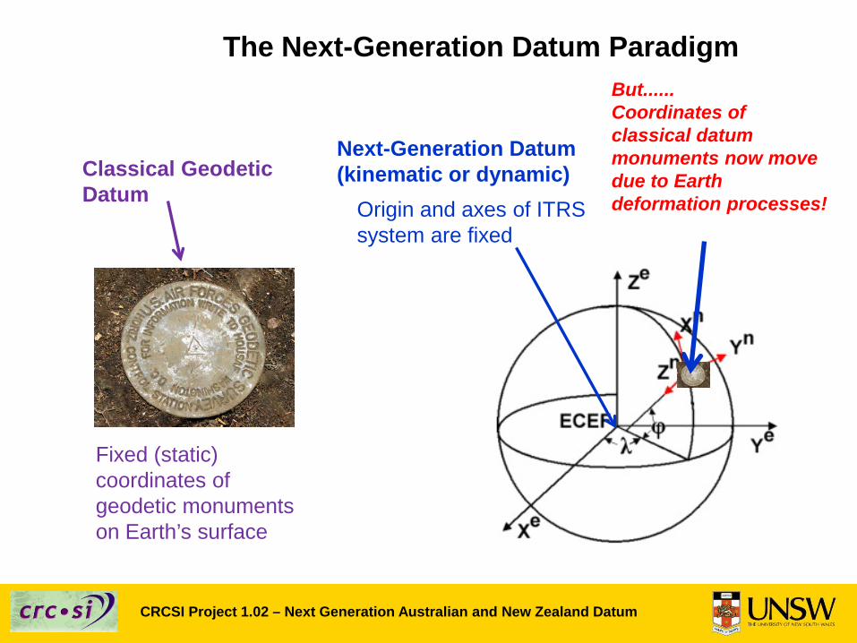
The Next-Generation Datum Paradigm
Classical Geodetic Datum
Fixed (static) coordinates ofgeodetic monumentson Earth’s surface
Next-Generation Datum(kinematic or dynamic)
Origin and axes of ITRS system are fixed
But......Coordinates of classical datum monuments now move due to Earth deformation processes!
CRCSI Project 1.02 – Next Generation Australian and New Zealand Datum
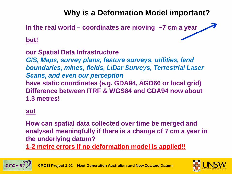
Why is a Deformation Model important?
In the real world – coordinates are moving ~7 cm a year
but!
our Spatial Data InfrastructureGIS, Maps, survey plans, feature surveys, utilities, land boundaries, mines, fields, LiDar Surveys, Terrestrial Laser Scans, and even our perceptionhave static coordinates (e.g. GDA94, AGD66 or local grid)Difference between ITRF & WGS84 and GDA94 now about 1.3 metres!
so!
How can spatial data collected over time be merged and analysed meaningfully if there is a change of 7 cm a year in the underlying datum? 1-2 metre errors if no deformation model is applied!!
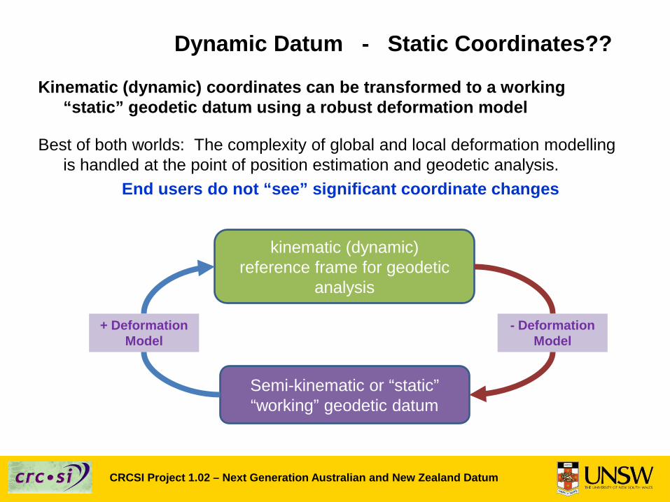
Dynamic Datum - Static Coordinates??
Kinematic (dynamic) coordinates can be transformed to a working “static” geodetic datum using a robust deformation model
Best of both worlds: The complexity of global and local deformation modelling is handled at the point of position estimation and geodetic analysis.
End users do not “see” significant coordinate changes
Semi-kinematic or “static” “working” geodetic datum
kinematic (dynamic)reference frame for geodetic
analysis
+ DeformationModel
- DeformationModel
CRCSI Project 1.02 – Next Generation Australian and New Zealand Datum
CRCSI Project 1.02 – Next Generation Australian and New Zealand Datum
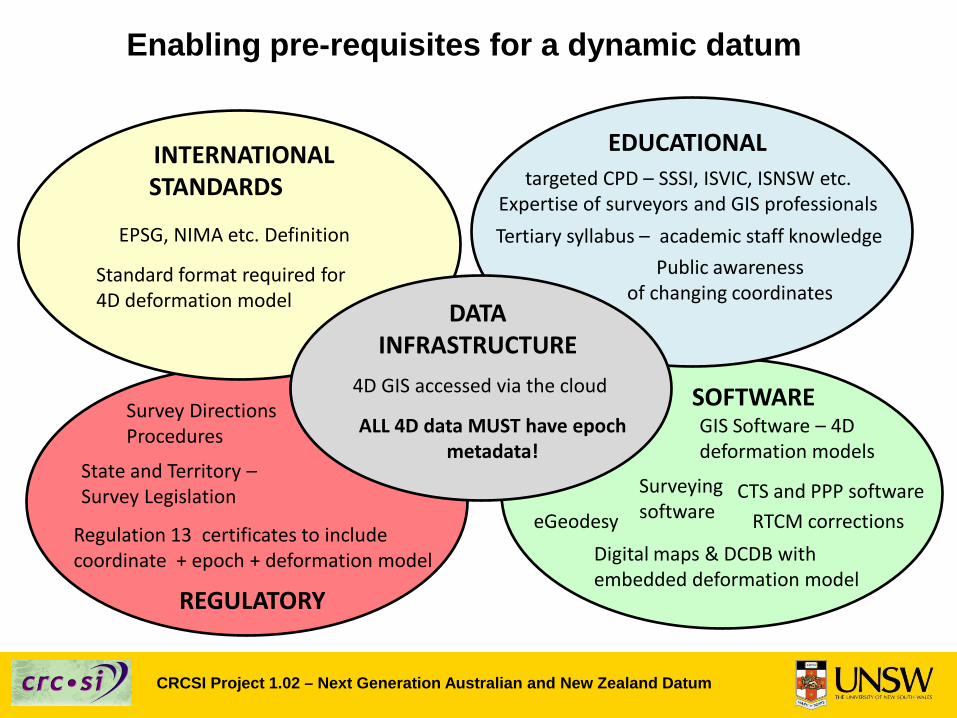
Enabling pre-requisites for a dynamic datum
REGULATORY
Regulation 13 certificates to include coordinate + epoch + deformation model
State and Territory –Survey Legislation
Survey Directions Procedures
SOFTWAREGIS Software – 4D deformation models
INTERNATIONALSTANDARDS
EPSG, NIMA etc. Definition
Standard format required for 4D deformation model
Surveying softwareeGeodesy RTCM corrections
EDUCATIONALtargeted CPD – SSSI, ISVIC, ISNSW etc.
Expertise of surveyors and GIS professionalsTertiary syllabus – academic staff knowledge
Public awarenessof changing coordinates
Digital maps & DCDB with embedded deformation model
CTS and PPP software
DATA INFRASTRUCTURE
4D GIS accessed via the cloud
ALL 4D data MUST have epoch metadata!
CRCSI Project 1.02 – Next Generation Australian and New Zealand Datum
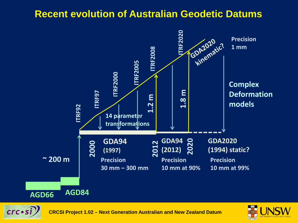
Recent evolution of Australian Geodetic Datums
AGD84
GDA94(1997)
~ 200 m
ITRF
92 ITRF
97 ITRF
2000
ITRF
2005
ITRF
2008
14 parametertransformations
2012
Precision 30 mm – 300 mm
1.2
mGDA94(2012)Precision 10 mm at 90%
2020
1.8
m
ComplexDeformationmodels
ITRF
2020
GDA2020(1994) static?Precision 10 mm at 99%
2000
Precision 1 mm
AGD66
CRCSI Project 1.02 – Next Generation Australian and New Zealand Datum
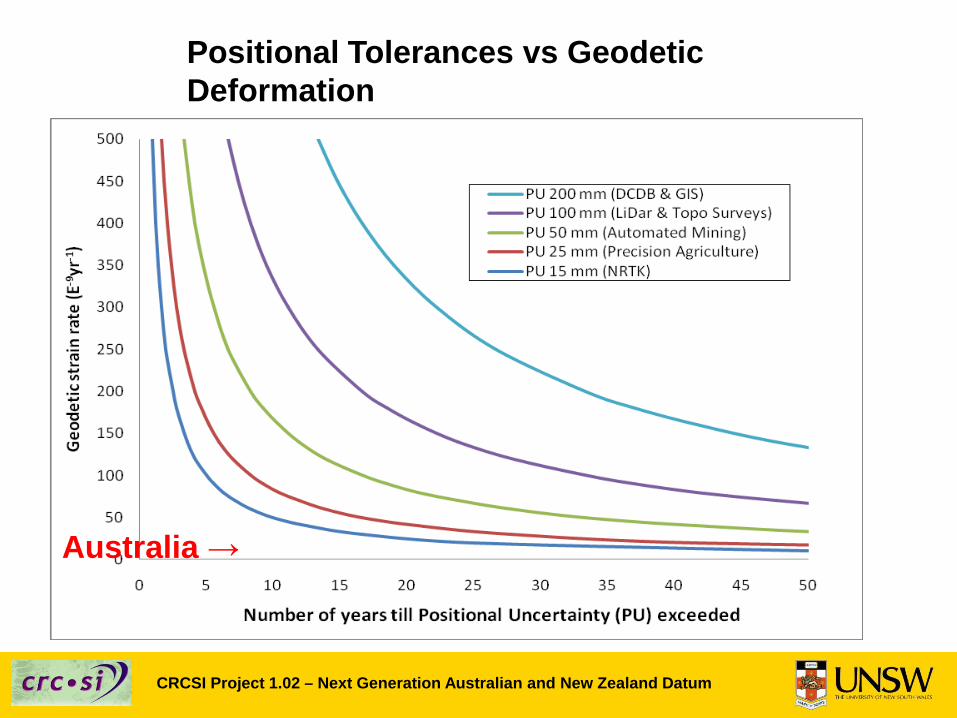
Positional Tolerances vs Geodetic Deformation
Australia →
CRCSI Project 1.02 – Next Generation Australian and New Zealand Datum
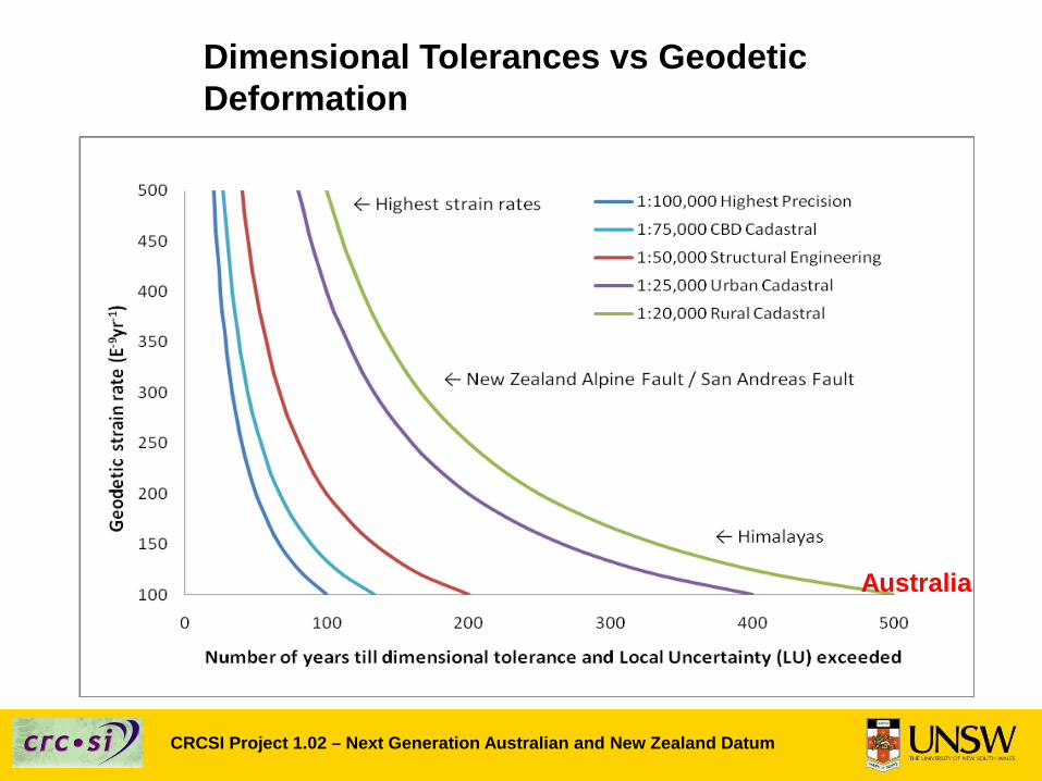
Dimensional Tolerances vs Geodetic Deformation
Australia

CRCSI Project 1.02 – Next Generation Australian and New Zealand Datum
Results in changes incoordinates of local frame- patch model
Deformation is “invisible”in local frame- secular model
Characterisation of Deformation
CRCSI Project 1.02 – Next Generation Australian and New Zealand Datum
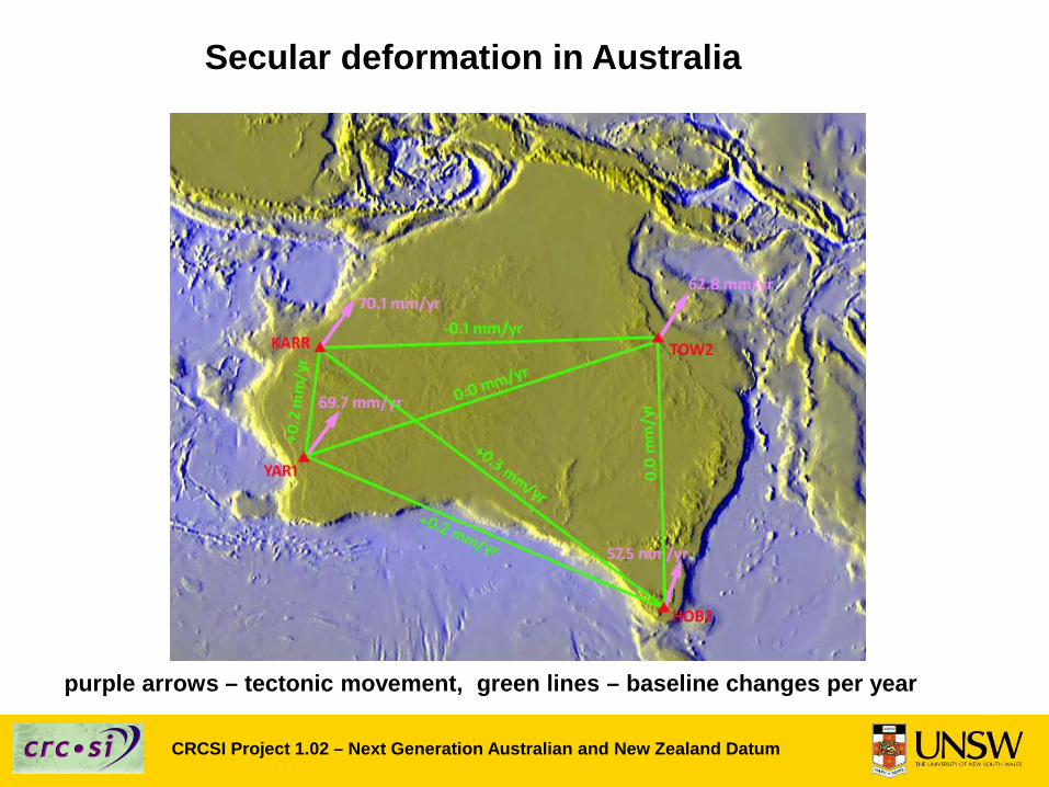
purple arrows – tectonic movement, green lines – baseline changes per year
Secular deformation in Australia
CRCSI Project 1.02 – Next Generation Australian and New Zealand Datum
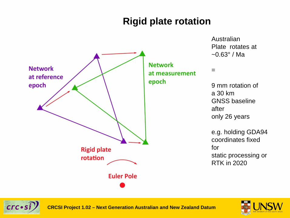
Rigid plate rotationAustralianPlate rotates at~0.63° / Ma
=
9 mm rotation ofa 30 kmGNSS baseline after only 26 years
e.g. holding GDA94coordinates fixed forstatic processing or RTK in 2020
CRCSI Project 1.02 – Next Generation Australian and New Zealand Datum
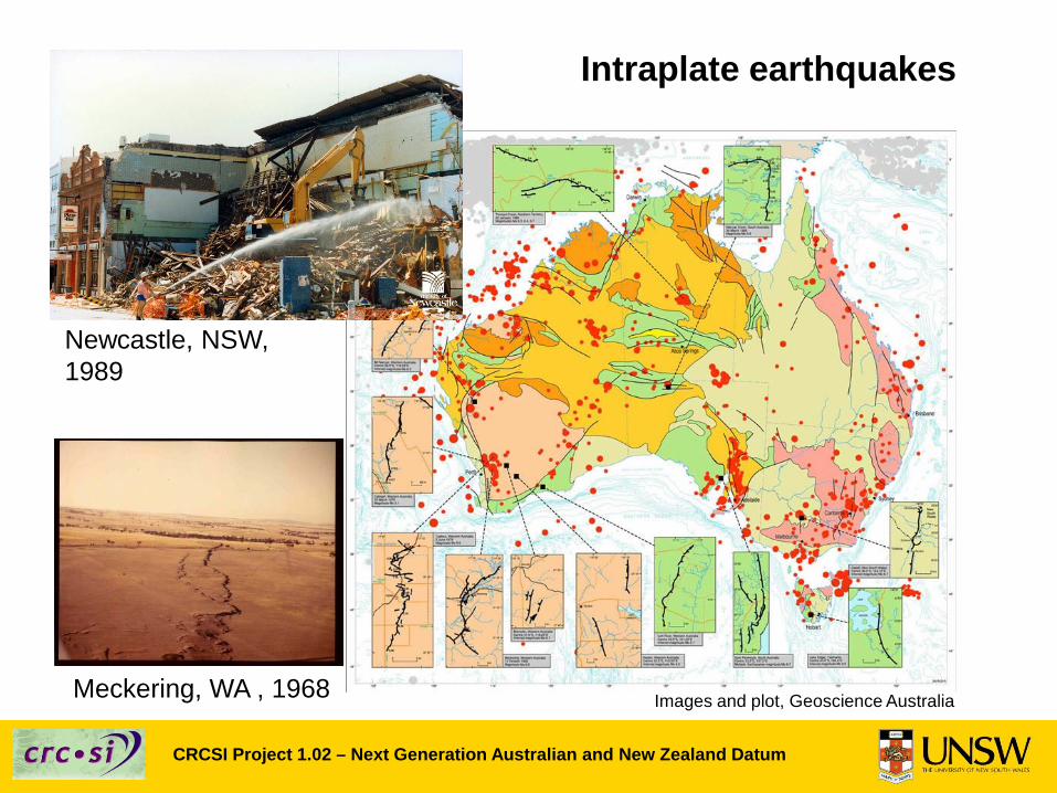
Intraplate earthquakes
Newcastle, NSW, 1989
Meckering, WA , 1968 Images and plot, Geoscience Australia
CRCSI Project 1.02 – Next Generation Australian and New Zealand Datum
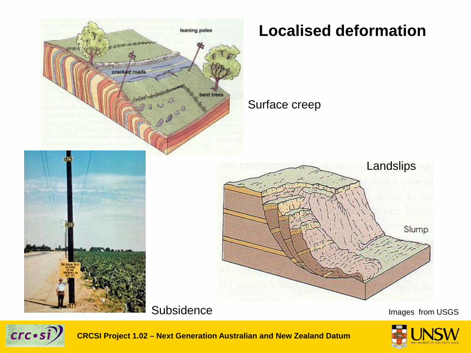
Localised deformation
Surface creep
Landslips
Subsidence Images from USGS
CRCSI Project 1.02 – Next Generation Australian and New Zealand Datum
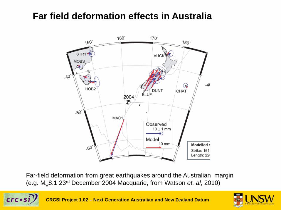
Far field deformation effects in Australia
Far-field deformation from great earthquakes around the Australian margin(e.g. Mw8.1 23rd December 2004 Macquarie, from Watson et. al, 2010)
CRCSI Project 1.02 – Next Generation Australian and New Zealand Datum
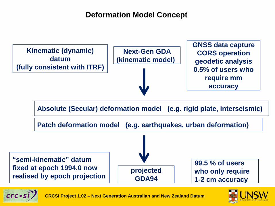
Deformation Model Concept
Absolute (Secular) deformation model (e.g. rigid plate, interseismic)
Kinematic (dynamic) datum
(fully consistent with ITRF)
Next-Gen GDA(kinematic model)
GNSS data captureCORS operation
geodetic analysis0.5% of users who
require mm accuracy
“semi-kinematic” datumfixed at epoch 1994.0 now realised by epoch projection
projectedGDA94
99.5 % of userswho only require 1-2 cm accuracy
Patch deformation model (e.g. earthquakes, urban deformation)
CRCSI Project 1.02 – Next Generation Australian and New Zealand Datum
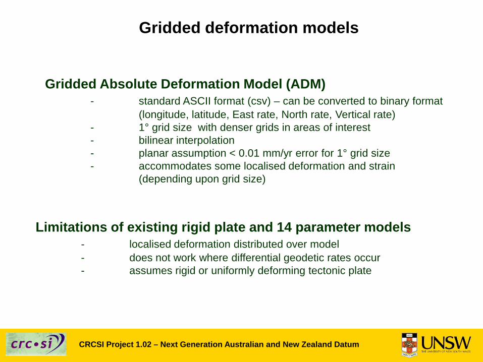
Gridded deformation models
Gridded Absolute Deformation Model (ADM) - standard ASCII format (csv) – can be converted to binary format
(longitude, latitude, East rate, North rate, Vertical rate)- 1° grid size with denser grids in areas of interest- bilinear interpolation- planar assumption < 0.01 mm/yr error for 1° grid size- accommodates some localised deformation and strain
(depending upon grid size)
Limitations of existing rigid plate and 14 parameter models- localised deformation distributed over model- does not work where differential geodetic rates occur- assumes rigid or uniformly deforming tectonic plate

CRCSI Project 1.02 – Next Generation Australian and New Zealand Datum
Australian Deformation Model Format – 2 components
1° 3D Grid Velocity Modelof estimated site velocities
1° 3D Grid Patch Modelof distortions and summed episodic deformation and distortion between reference epoch and epoch of patch model
Denser Grids (0.1°, 0.01°, or 0.001° or MGA 10 m Grid) in urban areas or areas of highly variable deformation
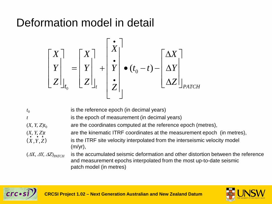
Deformation model in detail
t0 is the reference epoch (in decimal years)t is the epoch of measurement (in decimal years)(X, Y, Z)t0 are the coordinates computed at the reference epoch (metres), (X, Y, Z)t are the kinematic ITRF coordinates at the measurement epoch (in metres),( ) is the ITRF site velocity interpolated from the interseismic velocity model
(m/yr),(∆X, ∆Y, ∆Z)PATCH is the accumulated seismic deformation and other distortion between the reference
and measurement epochs interpolated from the most up-to-date seismic patch model (in metres)
0
0( )
t PATCHt
XX X XY Y Y t t YZ Z ZZ
•
•
•
∆ = + • − − ∆ ∆
, ,X Y Z• • •
CRCSI Project 1.02 – Next Generation Australian and New Zealand Datum
CRCSI Project 1.02 – Next Generation Australian and New Zealand Datum
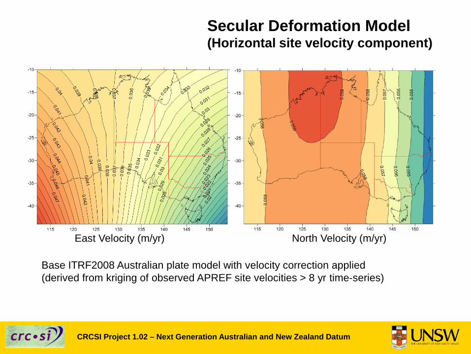
Secular Deformation Model (Horizontal site velocity component)
Base ITRF2008 Australian plate model with velocity correction applied (derived from kriging of observed APREF site velocities > 8 yr time-series)
East Velocity (m/yr) North Velocity (m/yr)
CRCSI Project 1.02 – Next Generation Australian and New Zealand Datum
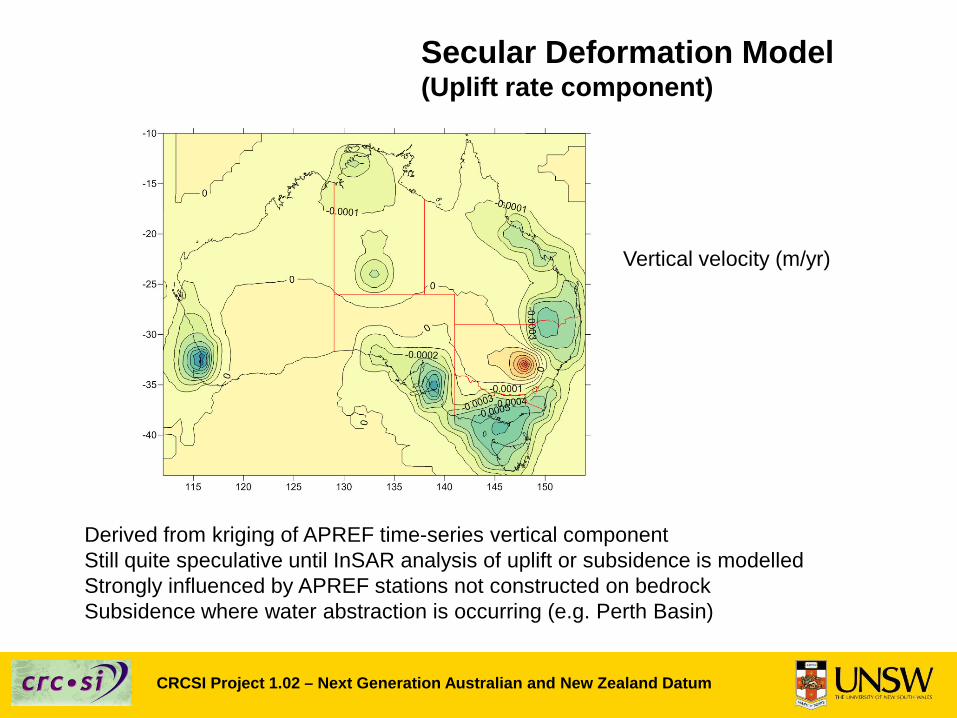
Secular Deformation Model (Uplift rate component)
Derived from kriging of APREF time-series vertical componentStill quite speculative until InSAR analysis of uplift or subsidence is modelledStrongly influenced by APREF stations not constructed on bedrockSubsidence where water abstraction is occurring (e.g. Perth Basin)
Vertical velocity (m/yr)
CRCSI Project 1.02 – Next Generation Australian and New Zealand Datum
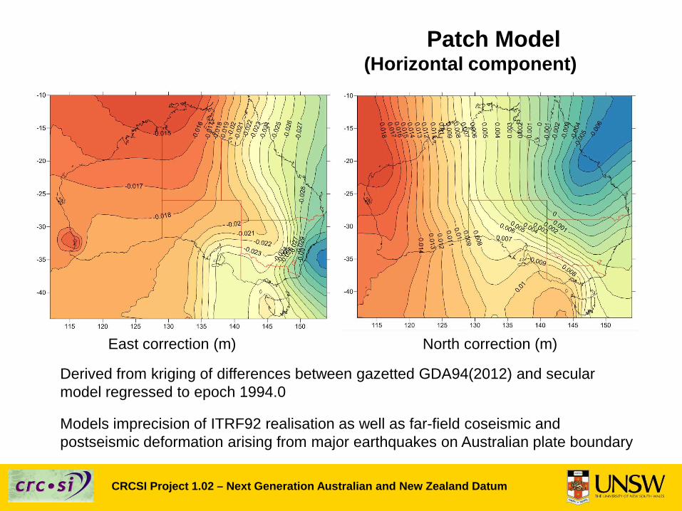
Patch Model (Horizontal component)
Derived from kriging of differences between gazetted GDA94(2012) and secular model regressed to epoch 1994.0
Models imprecision of ITRF92 realisation as well as far-field coseismic and postseismic deformation arising from major earthquakes on Australian plate boundary
East correction (m) North correction (m)
CRCSI Project 1.02 – Next Generation Australian and New Zealand Datum
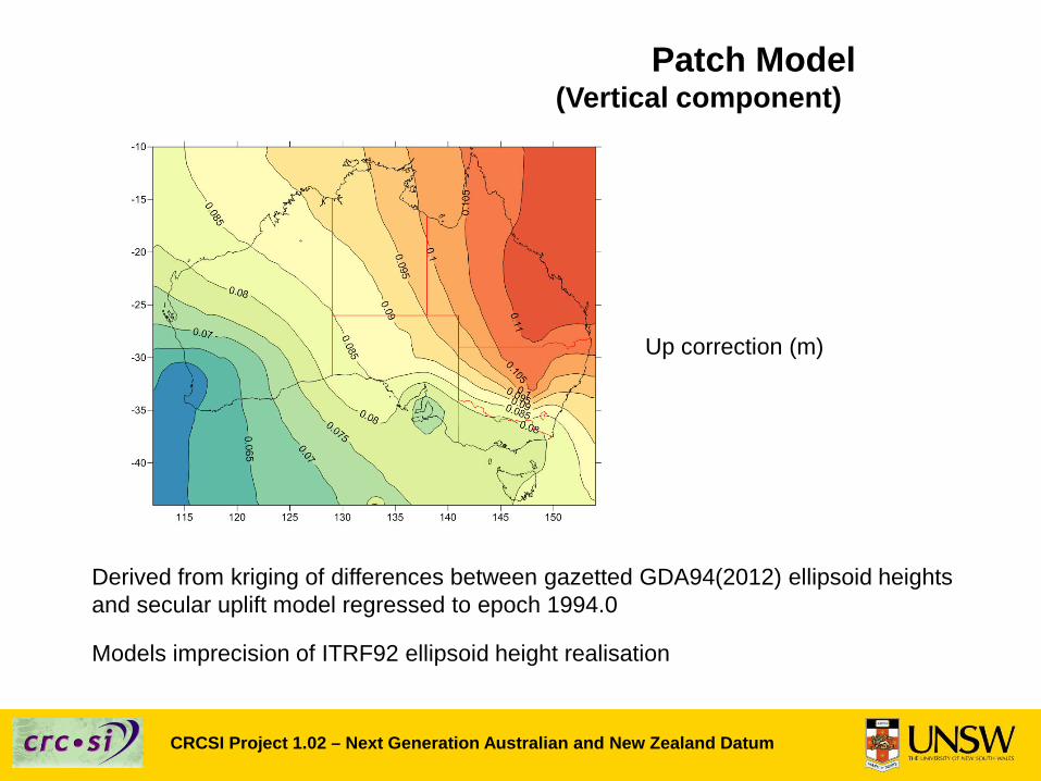
Patch Model (Vertical component)
Derived from kriging of differences between gazetted GDA94(2012) ellipsoid heights and secular uplift model regressed to epoch 1994.0
Models imprecision of ITRF92 ellipsoid height realisation
Up correction (m)
CRCSI Project 1.02 – Next Generation Australian and New Zealand Datum
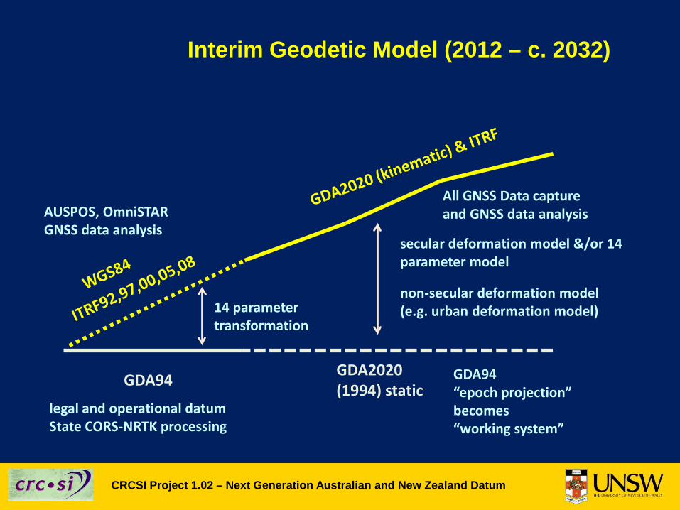
Interim Geodetic Model (2012 – c. 2032)
GDA2020(1994) staticGDA94
14 parametertransformation
AUSPOS, OmniSTARGNSS data analysis
All GNSS Data captureand GNSS data analysis
secular deformation model &/or 14 parameter model
non-secular deformation model(e.g. urban deformation model)
GDA94 “epoch projection” becomes “working system”
legal and operational datumState CORS-NRTK processing
CRCSI Project 1.02 – Next Generation Australian and New Zealand Datum
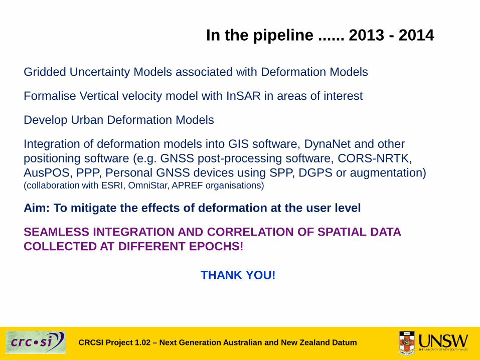
In the pipeline ...... 2013 - 2014
Gridded Uncertainty Models associated with Deformation Models
Formalise Vertical velocity model with InSAR in areas of interest
Develop Urban Deformation Models
Integration of deformation models into GIS software, DynaNet and other positioning software (e.g. GNSS post-processing software, CORS-NRTK, AusPOS, PPP, Personal GNSS devices using SPP, DGPS or augmentation) (collaboration with ESRI, OmniStar, APREF organisations)
Aim: To mitigate the effects of deformation at the user level
SEAMLESS INTEGRATION AND CORRELATION OF SPATIAL DATA COLLECTED AT DIFFERENT EPOCHS!
THANK YOU!