a comparison of the methods used in...
TRANSCRIPT

A comparison of the methods used indetermining azimuth by solar observations
Item Type text; Thesis-Reproduction (electronic)
Authors Murphy, Gerald Edward, 1931-
Publisher The University of Arizona.
Rights Copyright © is held by the author. Digital access to this materialis made possible by the University Libraries, University of Arizona.Further transmission, reproduction or presentation (such aspublic display or performance) of protected items is prohibitedexcept with permission of the author.
Download date 07/07/2018 05:52:27
Link to Item http://hdl.handle.net/10150/319786

A COMPARISON OF THE METHODS USED IN DETERMINING
AZIMUTH BY SOLAR OBSERVATIONS
by
. Gerald E. Murphy
A Thesis Submitted to the Faculty of the
DEPARTMENT OF CIVIL ENGINEERING
In Partial Fulfillment of the Requirements For the Degree of
MASTER OF SCIENCE
In the Graduate College
THE UNIVERSITY OF ARIZONA
1964

STATEMENT BY AUTHOR
This thesis has been submitted in partial fulfillment of requirements for an advanced degree at The University of Arizona and is deposited in The University Library to be made available to borrowers under rules of the Library.
Brief quotations from this thesis are allowable without special permission, provided that accurate acknowledgment of source is made. Requests for permission for extended quotation from or reproduction of this manuscript in whole or in part may be granted by the head of the major department or the Dean of the Graduate College when in their judgment the proposed use of the material is in the interests of scholarship. In all other instances, however, permission must be obtained from the author.
SIGNED: ^
APPROVAL BY THESIS DIRECTOR
This thesis has been approved on the date shown below:
^PHlIlP B. NEWlAN DateAssociate Professor of Civil Engineering

TABLE OF CONTENTS
Page
LIST OF PLATES o e o e o o e e e e o o o e e a o o o e Q o o o o e e e o o o o e o e e e e t o o o o e e o e o e G I V
LIST OF I LLUSTRATI ONS ©eoooooefroeeGeeooeoooeoeeGeoseooooec-oocooe V
INTRODUCTION o©ee©e«e»»t»©©oo©e®<a©»eeoo©eeoo©eieo©ovo©<aoGUG©c<5o»<i» X
CHAPTER I
THE HISTORY, ADVANTAGES, AND DISADVANTAGES OF SOLAR OBSERVATIONS
The History of Solar Observations »e»,,,*co 3Advantages 00G0etieeo0ee®©6000e9000tf0»000»e000eGe000@e»oe0e-g©cc»0 VDisadvantages e©o®epeoe6oc<8©e6ooeoso6oo6©9oee®e©eo©©»©<eo#ee©oet30 9
CHAPTER II
DETERMINATION OF AZIMUTH BY SOLAR OBSERVATION
DefimtlOnS and Notations o o c e e © o » e b e o © » e e o » © © © e © e © o © e e o o « > y e © © e e XXThe AStrOnOIDlCal Triangle o60©©oo©eGOOoeoooeaooo©o©eeeo«ee©oo©e© X^B aS 1 0 Equati ons » e © e » e t » e e o t i o o e o o o c i o o e o o e e e © e » o e o o o o o o © » o © © » < i Q c o 13
CHAPTER III
METHODS OF OBSERVING THE SUN
Solar Screen o o c o © © e o c e D » o » © o o e o © o e © © 6 e s o o e o o © © e © o e o e e a e o o G o 6 o e e 17Solar Filter e o e e e o © o o 6 o © © ® e e » o 6 o o e © o ® © o © © o © o o © & o o e © o © o o o © o © o e c e 2 4S O la r Re tic le G ® © o © » e o o e o t > o © » o c o » © © e ® o » o o e o o o s © © © o © e e e o e o < » o o a o ® e 20Simplex S d a r Shield © o © o e o e » e o o o o e © o o o e » © » e e e © e o o e e e © « c o 0 © c 6 o © o 27RO0 IpfS S d a r Prism eeoeeooo©e©ee»oo6<>©©®oooeeeoocQ"eo»c©©©ci<?»D» 28
111

CHAPTER IViv
CORRECTIONS FOR THE SUN’S CURVATURE AND SEMIDIAMETER
■ PageS e ITil c3.1 ame *t elP oeeeoQeooeoeeoeooeoesoooe. ee^tieoeoeoeoooeoeeeecoeeeo-- 31 Curvature Correction ©©©©©©©©©©©©©©©©©©©©©©©©©©©©©©oo©©©©©©©©©©© 34Semidiameter Correction ©©©©©©©©©©©©©©©©o©©©©©©©*©©©©©©©©©©©©©©© 36
CHAPTER V
DETERMINING DECLINATION, LATITUDE,AND LONGITUDE
Declination ©©©©©©©©©©©©©©©©©©©©©©©©©©©©©©©©©©©©©©o©©©©©*©©©©©©© 42Latitude ©©©©©©©©©©©©©©©©©©©©©©©©©©©©©©©©©©o©©©©©©©©©©©©©©©©©©©© 45Longitude ©©o©©©©©©©©©©©©©©©©©©©©©©©©©©©©©©©©©©©©©©©©©©©©©©©©©©© 46
CHAPTER VI
AZIMUTH BY THE ALTITUDE OF THE SUN
l o o t i o o e e e e e c e e o o o
Introduction ©©©©©©©©©©©©©©©©©©©©©©©©©©©o©©©©©©©©©©©©©#©©©©©© Trigonometric Formulas ©©«©©©©©©©©©©©©©©©©©©©©©©©©©©©©©©©©©©© Factors Affecting the Measuring of Altitude ©Effect of Errors in Altitude on the Computed Azimuth © ©Effect of Errors in Declination on the Computed AzimuthEffect of Errors in Latitude on the Computed Azimuth ©©©©.©©©©Field Procedure for Observations
51515465677173
CHAPTER VII
AZIMUTH BY THE HOUR ANGLE OF THE SUN
Introduction ©©@©©©©©©©©©©©©*©©©©©©©©©©©**©©©©*©©©©©©©@©©©©@©0 ©© 76Determining the Hour Angle of the Sun .©...©.©©..«..© .©©»»©©.©. © 78Factors Affecting the Measurement of the Sun's Hour Angle 81Field Procedure for Observations 85

CHAPTER VIII
OTHER METHODS OF DETERMINING AZIMUTH BY THE SUN
Azimuth by the Altitude and Hour Angle of the Sun Ec^ual Altitude Method e>©o©®®G©oooo©®9 oo©ooooo©ocfc
CHAPTER IX
COMPUTATIONS
Introduction o©©©©©©©©©©©©©©©©©©©©©©©®©©©©©©©©©©© Slide Rule o©©©©©©©©©©©©©©©©©©©©©©©©©©©©©©©©©©©©© Logarithms ©©©©©©©©©©©©©©©©©©©©©©©©©©©©©©o©©©©©©© Natural Functions ooeooo©©©©©©©®©©©©©©®©©©©©©©©©© Electronic Digital Computer Hour Angle Program
0 0 6 6 0 6 0 0 6 6 9 0
6 0 6 0 0 0 0 0 0 0 0 6 6 0 0 0 0 6 0 6 6 0 0 0 6 0 6 0
CHAPTER X
CONCLUSION
C O n d U S l O n o o o o o o o o e e o e o e o o o o o o e o e e o o e o o e o e o o e o o
BIBLIOGRAPHY o e o O o o c e o o o o o o o o o o e o o o s a d o a o o o o e e o o o

LIST OF PLATES
Plate Page
1 Computation of Sun9s Declination 44
2 Telescopic Solar Declination Setting e * , * , * . * . , . . 46
3 Determination of Azimuth by Log Secants „»* * *„*»,»*,* * * a 55
4 Alt ltude« Azimuth Curves »ec>»©ooo6eot>oooo6oeoeeoeoeoooo6» 68
5 Effect of An Error In Declination on The Sun9sHearing efeoooo&oooooefcQCtoO’eefreoooooeoeeeeoooeoooooo 70
6 Effect of Latitude and Hour Angle on dB/dPhi © „o * . 72
7 Altitude«-Azimuth Curves With dB/dPhi© CurvesSuperimposed ©©©eo©©©©©©©©©©©©©©©©©©©©©©©©©©©©©©©©© 74
8 Error In Azimuth For One Second Error In Time ©»© © © © © © © © 86
vi

LIST OF ILLUSTRATIONS
Figure
1
23
4
5
67
8 9
10
1112
13
14
15
16
17
18
19
20
r o o o e e o o o o e e o o o o o o o e o t i o t i e o o o e t e o o o o e o o o o e o o
o f r o e e e o o o e o e t o o o o e q & o e e o o o e e o o o G Q Q O o o o o o o
Groma .........
Indian Circle ,
Celestial Triangle ..........
Spherical Triangle
Quadrant-Tangent Method
Center-Tangent Method
Bisect! On e e o o e e e e e o o e e o o e e e c o . e o o o o o c e e e o e e o e e o e e o e e c e e o e o
e e e o e o e e e e o o o o o o y o o e o e f r o o o o o
' O o o o o e e e o o o o o 6 e > e e p o e o © 6 e © , o o o e d o o e o '
e e e e e o o o o o o e o o o o o e o i y o o o o o e e
Page
4
5
„ 12 . 14
19
e e e o o o e e o o o o o o O e e o e o o e o e o & e c e o o o e o o
Solar Filters Quadrant-Tangent Method
Solar Filters Center-Tangent Method ,
Solar Reticle
Roelofs9 Solar Prism
Semidiameter Correction
e o e o e e e e o o d e o f l o o o e o
o 0 © o o o
o d e e e e e e o e e o e o e e ' e a
i e © e e © o e 1
Horizontal Angle Correction for Sun 9s Angular Semidiameter „*,* * *,„
Effect of Curvature ••
Effect of Semidiameter
Quadrant-Tangent
e o c c o o o c ^ o
© o e e e e o o e o e e f e a e c e
Accuracy of Measuring Latitude «
Accuracy of Measuring Longitude
© e e o e o o o o o o o o e o e o e o e e e . t i i
© © o o B o o a o o o o o e o o o o o o o o
A o o e o o o e e e o o e o B o e o o o o o i
o o o o o e o o o o a o
o e e e o o e o o o
o o o o o o o q o o o e > © o o o
o e e e o o e o o e o o o o o e o o e o o o o
o o o o e o o e
XnStrUmeTit Error eeooooooooooo&doeooooosooeeeooooooooooool
Refraction Q © © © s © © o ©«© © © © o © o o o o o c o e e o o o e o o o e o o o o o o o o e
2123
25
25
26
29
31
33
35
37
39
47
49
57
60
vii

viiiFigure ' Page
2 3L P erS i 3-SX. o * e e o o d e » o o e o e e o e o o e o o » Q o o » e o e i ? o e e o o t i o o < ) o e o @ o # e e o 03
22 Relationship Between the Greenwich Hour Anglean (1 Local Hour Angle o c e o e e e e o o e o o o e e o e o t i e e o o e o e o o o o e 61

A COMPARISON OF THE METHODS USED IN DETERMINING
AZIMUTH BY SOLAR OBSERVATIONS
By
Gerald E. Murphy
Abstract
A number of methods are available to determine azimuth
by the sun. The basic equations are derived and each method
examined. Devices for pointing on the sun are discussed in
detail. All factors that are related to the computed azimuth
such as declination, latitude, and longitude are considered along
with the measurement of each. The altitude and hour angle methods
are compared and the factors affecting the accuracy of each
method discussed. The solar equations can be solved in a number
of ways. The standard methods of performing the computations are
reviewed and a digital computer program to solve the hour angle
.equation is presented.
ix

INTRODUCTION
The science of surveying had its birth at the time man first
recognized the right of private ownership of land* This recognition
was impossible without boundaries9 no matter how crude* to delineate
one manffs holdings from his neighbors* As populations increased and
land became more valuable the status of the land surveyor grew* In
540 A * D * Cassiodorus wrote the following concerning the place of the
land surveyor in Roman life*
The professors of this science [of land surveying] are honored with a most earnest attention than falls to the lot of any other philosophers* Arithmetic9 theoretical geometry9 astronomy9 and music are discoursed upon to listless audiences9 sometimes empty benches6 But the land surveyor is like a judges the deserted fields become his forum9 crowded with eager spectators* You would fancy him a madman when you see him walking along the most devious paths* But in truth he is seeking for the traces of lost facts in rough woods and thickets* He walks not as other men walk* His path is the book from which he reads % he shows what he is saying; he proves what he hath learned; by his steps he divides the rights of hostile claimants; and like a mighty river he takes away the fields of one side to deposit them on the other,^
The measurement of distance and the determination of direc
tion were an essential part of these early surveys* It seems highly
possible that the lofty position held by the land surveyor in early
^-Edmond R* Kiely* Surveying Instruments: Their History andClassroom Useg Bureau of Publications* Teachers College* Columbia University$ New York, 1947, page 43*
1

Roman times was partly due to the skill he had developed in determin
ing direction. The use of the sun and stars to establish the meridian
surely impressed the landowners of Rome,
The present day land surveyor is still called upon to determine
the true bearing of boundary lines. Most of our state and county
boundaries9 and all surveys of the public lands of the United States
since 18559 are defined in terms of astronomic or true north$ Celes
tial observations are the only means of establishing a true meridian.
The following chapters compare the methods used in determining this
meridian by observations on the sun.

CHAPTER I
THE HISTORY„ ADVANTAGES„ AND
DISADVANTAGES OF SOLAR OBSERVATIONS
The History of Solar Observations
The practice of determining azimuth by the sun can be traced
to the earliest Etruscan historyc In the sixth century B.C, these
people established the meridian by the rising and setting of the srnn
The method consisted of staking the east-west line e the decimanus, by
observing the sun at its first appearance in the morning and again as
it set in the afternoon. The north-south line, the cardo, was
established by means of the groma» A sketch of the groma is shown in
Fig, 1,
The groma was used to construct a perpendicular to the decim
anus, The Etruscans were aware of the fact that this method gave the
true meridian only at the time of the equinoxes, In their writings
they recommend that the decimanus be established only from the shadow
of the sixth hour.^
Another early method of establishing the meridian was known
as the Indian Circle Method. The. oldest Indian description of this
method is to be found in the Surya Siddhanta., an astronomical work
j-Ibid., page 32 ■
3

dating from about 400 B.C.^4
\
Fig. 1.— Groma
The method was as follows: A circle was drawn on a carefully
leveled section of ground, A vertical rod was placed at the exact
^Ibid., page 61

center. When the extremity of the stick's shadow touched the circle both
in the morning and afternoon a point was marked. Fig. 2 shows the
Indian Circle with straight lines connecting the two points and the
center of the circle.
Fig. 2.— Indian Circle
The bisection of the lines formed was the true meridian.
Bisection was accomplished solely by means of measured distances in
much the same manner as described in present day surveying textbooks.
The Romans adopted the Indian Circle method and it was used
extensively for the establishment of street lines and the determination
of boundaries.
The Moslems introduced various refinements to the Indian
Circle method. One important contribution was the use of a number of
concentric circles instead of one. This made it possible to mark a
number of points on different circles in both the morning and after

noon. Better accuracy was obtained and the meridian could still be
determined even if clouds obscured the sun for a portion of the day.
The determination of azimuth was important to the Moslems both in
their astronomical work and in determining the direction of Mecca for
some of their religious rituals.
The accuracy of the Indian Circle method can be more appreciated
when compared with the magnetic compass. The earliest records of
scientific observations on the variation of magnetic declination were
made by Felipe Guillen in 1525,*^ JBy means of the Indian Circle
method he determined the meridian and then found the angle between the
compass needle and the meridian.
The first tables of the sun*s declination were published in
Hebrew in 1473 by Abraham Zacuto, They were later translated into
Latin by Jose Vizinto, These tables and other useful information to
mariners were printed in manuals or regimentos. They were used to
calculate latitude by meridian altitude observations of the sun.
The early property surveys in the New Wprld were made with
instruments and methods little better than those used in ancient times.
Direction was usually determined by magnetic compass. The variation
in magnetic declination was checked by observations of Polaris at
elongation,
LIbide * page 214,

The rectangular surveying system used in the United States
is dependent on the establishing of cardinal courses for controlling
lines„ The early surveys of the public land were dependent on the
needle compass for direction* The compass was first referenced to
magnetic north and the magnetic declination was then turned off* As
the surveys progressed into the upper regions of the Great Lakes the
magnetic compass proved so erratic that its use had to be discontinued*
The Burt solar compass was introduced in Northern Michigan
about 1836o* The solar unit, was later mounted on the telescope of a
transit* The use of solar observations proved both reasonably
accurate and relatively inexpensive in the survey of the public domain*
The development of optical transits and the improvement of
methods of pointing on the sun have made solar observations an im
portant part of modern surveys*
Advantages
The surveyor who rises at some darks frigid hour to observe
Polaris at elongation can readily understand one advantage of deter
mining azimuth by solar observation* Solar shots are taken only in
the daytime and usually during regular working hours* Avoiding a
special trip to the field for the sole purpose of taking a star shot
^The Gurley Telescopic Solar Transit: Its Use and Adjustments9Bulletin No. 112-T* W. 6 L* E. Gurley, Troy* New York* page 15*

could mean a substantial savings in the cost of a surveye
Working in daylight hours offers several advantages» In
remote areas and in rugged terrain9 it is much easier to find the
instrument station9 and there is no need to occupy the target station
for the purpose of illuminating the target* Instrument setups are
faster % and there is less danger of accidently disturbing the transit
by bumping a tripod lege Mistakes in reading and recording both angles
and time are fewer than when working in semi~or total darkness*
Solar observations can be successfully made when observing
conditions are relatively poor. Partly cloudy and hazy conditions
that would prevent a Polaris shot seldom interfere with a solar
observation.
In northern latitudes9 observations of Polaris, require rel
atively large vertical angles in comparison with solar shots* This
will result in proportionally large errors in vertical and horizontal
angles if an instrument is in poor adjustment. The error in the
horizontal angle for a one minute inclination of the vertical axis is
four times as great for a vertical angle of forty-five degrees as
compared with a vertical angle of fifteen degrees
^Raymond E. Davis and Francis S e Foote9 Surveying: Theoryand Practice* McGraw-Hill Book Company9 Inc,s New York, fourth editions 19539 page 305.

Disadvantages
The size and brightness of the sun are probably the major
drawbacks in solar observations* Its large size makes it difficult
to point at its exact center* Several methods of pointing and
numerous devices have been used9 but none so simple or accurate as
pointing on a star* The extreme brightness of the sun requires the
use of a darkener or solar screen to prevent serious damage to the
observer8s eye*
The computations required to determine azimuth by the sun are
longer and more complicated than those used in reducing a Polaris
observation* An error in computing the bearing of Polaris will
result in an azimuth that at most is wrong by two or three degrees,
whereas an error in computing the bearing of the sun may give an
absurd answer*
Parallax is an added correction that must be considered on
solar shots that can be ignored on other stellar observations*
Several other factors that affect any survey work performed
in direct sunlight should be mentioned* "Surface wind speed is
usually at a minimum about sunrise and increases to a maximum in
early afternoon * Atmospheric conditions are much more variable
and result'in unequal atmospheric refraction* The sun8s rays often
strike one side of the instrument while the other side remains
* Ray K* Linsley% Max A* Kohler9 and Joseph L* H* Paulhus9 Hydrology For Engineers, McGraw-Hill Book Company* Inc,, New York, 1958, page 21/

10
shaded* This results in a temperature difference and unequal expansion
of parts of the telescope*
Conditions most favorable for the precise measurement of angles
are in direct conflict with the requirements for solar observations*
The use of umbrellas* overcast skies* or nighttime observations are
impossible when determining azimuth by the sun*

CHAPTER II
DETERMINATION OF AZIMUTH BY
SOLAR OBSERVATIONS
Definitions and Notations
The determination of azimuth by solar observation requires
that a system of coordinates be used that will enable the surveyor
to compute the bearing of the sun* A number of astronomical systems
of coordinates are in common use at the present time» Only two of
theses the horizon system and the equator system9 are needed in
determining azimuth by solar observation0 Fig. 3 shows the celestial
triangle5 both in the horizon and equator system. To understand the
celestial triangle, a number of terms must be defined in each system
and their notation given.
The Horizon System
Celestial Spheres An imaginary sphere of infinite radius
with its center at the center of the earth.
Sun (S): The star nearest the earth about which the earth
revolves«,
Zenith (Z): A point directly overhead. This would be the
point at which a plumb line projected upward would pierce the
celestial sphere.
Nadir: The point directly opposite the zenith on the
celestial sphere.
11

12
o "
Fig. 3.— Celestial Triangle
Horizon: A great circle defining the intersection of the
celestial sphere and a plane perpendicular to the line joining the
zenith and nadir and halfway between these points.
Vertical Circles: Great circles passing through the zenith
and nadir.
Meridian: The vertical circle which passes through the
celestial poles.
Azimuth (B): The azimuth of the sun is the angle at the
zenith measured eastward or westward from the meridian to the verti
cal circle through the sun.

Altitude (h): The sunes angular distance above the horizon,
It is measured upward on the vertical circle through the sun from the
horizon to the sun®
Zenith Distance (z)i 90°«h
The Equator System
Celestial Equator: The intersection of the plane of the
earth9s equator with the celestial sphere«>
Celestial Poles (P): The two points where the axis of ro
tation of the earth extended pierces the celestial sphere®
Hour Circle: Great circles perpendicular to the equator and
passing through the celestial poles.
Meridian: The hour circle through the zenith of an observer.
Hour Angle (t): The angle at the pole from the meridian
westward to the hour circle through the sun.
Declination (Dec.): The angular distance measured on the
hour circle through the sun from the equator to the sun. It is
positive when measured northward from the equator and negative when
measured southward.
Polar Distance: 90o-Dec»
Latitude (Phi*): The angular distance of the observer north
or south of the equator measured along a meridian of longitude0
Longitude: Angular distance of a meridian east or west of a
starting meridian through Greenwich^ England& measured along the
equator*

14
The Astronomical Triangle
The astronomical triangle, like any spherical triangle, has
certain relationships between its sides and its angles. These laws
are derived in any text on spherical trigonometry and the derivation
will not be repeated. Referring to Fig. 4.(a) the three most important
formulas in the solution of any spherical triangle are:
B
( a) (b)
Fig. 4.— Spherical Triangle
The law of sines.
sin A _ sin B _ sin C (sin a sin b sin c
The law of cosines.
cos b = cos a x cos c + sin a x sin c x cos B ........ (2)
Relationship between two angles and three sides.
sin a cos B = sin c x cos b - cos c x sin b x cos A (3)

15
The application of these three laws to the astronomical
triangle results in the basic equations for determining azimuth.
Basic Equations
The astronomical triangle is shown in Fig. 4.(b) and equations
(1), (2), and (3) applied.
The law of sines.
sin B _ sin tsin (90°-Dec.!) sin (90o-h)
or
cos Dec. x sin t /ltXSln B = (1,)
The law of cosines solving for B.
cos (90°-Dec.) = cos (90°-h) x cos (90°-Phi.)
+ sin (90°-h) x sin (90°-Phi.) x cos B
After reduction this equation becomes
sin Dec. = sin h x sin Phi. + cos h x cos Phi. x cos B
or
D _ sin Dec. - sin h x sin Phi. ,c\COS B - ■ .. ... .. . Ko)cos h x cos Phi.
The law of cosines solving for t.
cos (90°-h) = cos (90°-Phi.) x cos (90°-Dec.)
+ sin (90°-Phi,) x sin (90°-Dec.) x cos t
After reduction this becomes

16
sin h = sin Phi. x sin Dec. + cos Phi. x cos Dec. x cos t
or
+. _ sin h - sin Phi. x sin Dec.COS L w ■ — 1*1 I w n > T ■! n I I ■ 1 m -cos Phi. x cos Dec,
Relationship between two angles and three sides.
sin (90°-h) x cos B = sin (90°-Phi.) x cos (90°-Dec.)
- cos (90°-Phi.) x sin (90°-Dec.) x cos t
After reduction this becomes
cos h x cos B = cos Phi. x sin Dec.
- sin Phi. x cos Dec. x cos t .......... .
Another useful equation can be developed by dividing Eq. (7) by Ec
cos h x cos B _ cos h x sin B
cos Phi, x sin Dec. - sin Phi, x cos Dec. x cos t cos Dec. x sin t
or
(7)
. (4).
cos Phi. x tan Dec. - sin Phi. x cos tcot B --------------------JJ— -------------------

CHAPTER III
METHODS OF OBSERVING THE SUN
Solar Screen >r
Viewing the sun directly through a telescope may result in
serious injury to the observer's eye. There are several safe ways
of pointing a telescope at the sun. The solar screen is probably
the most commonly used method of viewing the sun. The observation
can be made with any transit that contains a vertical limb. The
screen may consist of a special attachment supplied by the instrument
manufacturer9 but more often it is simply a white card held by hand
a few inches back of the eyepiece® The advantage of the attach
ment is that the screen remains perpendicular to the axis of the
telescope and at a fixed distance from the eyepiece. In either case
the screen is used to reflect the sun*s image.
The sun is sighted by pointing the telescope in the direction
of the sun and observing the shadows cast by the telescope vial
posts* When the shadows appear to coincide the azimuth motion is
locked. The telescope is then rotated about its horizontal axis
until the image of the sun flashes across the screen® The vertical
motion is then locked. By carefully focusing both the objective lens
and the eyepiece* the shadows of the cross wires are visible against
a sharp image of the sun,
i.

18
When using a solar screen there is still the problem of
pointing at the center of the sun* The pointing can be accomplished
by any of the following methods«
Quadrant-Tangent Method
The sun9s image is brought into view on the solar screen in
such a position that it is tangential to both the horizontal and
vertical cross wires* At the moment of tangency the time9 vertical
anglef and horizontal angle are read and recorded* Knowing the semi
diameter of the sun the correct vertical and horizontal angle to the
sun9s center can be computed*
An easier method of obtaining the correct vertical and hori
zontal angle to the sun*s center requires taking observations in
pairs* The second pointing places the sun9s image in a diagonally
opposed quadrant from the first* Assuming the path of the sun is a
straightline between pointings9 the mean of the-vertical and hori
zontal angles requires no correction.
Since the sun is moving rapidly in both altitude and azimuth 9
it is difficult to follow it by manipulating both motions of a
transit* Sighting can be simplified by selecting a quadrant in which
the sun9s image is moving toward one cross hair and away from the
other. One wire is set to cut a segment of the sun*s image that is
moving away from the cross hair® This wire is then kept stationary
while the sun is tracked with the other wire* The instant the edge
of the sun becomes tangent to the stationary wire, all motion is
stopped* By this method a simultaneous tangency can be obtained*

19
The correct quadrant to place the image of the sun is
dependent on when the observation is made and the type of telescope.
Fig. 5 shows the image of the sun as it appears on a solar screen with
an erecting telescope.
A.M.
Hor. Wire Stationary
Vert. Wire Stationary
P.P.M
Hor. Wire Stationary
Vert, Wire Stationary
Fig. 5.— Quadrant-Tangent Method
When an inverting telescope is used Fig. 5. should be turned
upside down.
A number of different procedures are used when taking a series
of observations by the quadrant-tangent method. The K 6 E Solar
Ephemeris recommends taking at least three successive readings with
the sun's image in the same quadrant before the telescope is reversed.
An equal number of pointings are then made in the diagonally opposed
quadrant. The averages of the times, vertical angles, and horizontal
angles are used to compute the bearing. This method is subject to
rather large curvature errors since a time lapse of ten to fifteen

20
minutes may occur between the initial and final sighting*
A more refined method of observing is used by the Bureau of
Land Management* They treat each pair of observations as a series and
from the average readings compute an azimuth* A total of three sets
are taken and the average value of the three computed azimuths used as
the true bearing*
The Geological Survey recommends a total of ten observations*
Five sightings are taken with the sun in the same quadrant* Upon
completion of the fifth pointing the initial station is sighted* The
telescope is then reversed and five pointings taken in the diagonally
opposed quadrante The mean values of the ten pointings are used in
computing azimuth. The Geological Surveyb method of reading horizon
tal angles differs from most procedures. The A vernier is read for
all pointings with telescope direct and the B vernier for all
pointings with the telescope reversede This method enables the
observer to read the angles faster, and there is less danger of
accidently bumping a tripod leg* A time limitation of ten minutes is
used between the first and last pointing.
When using the average values of several pointings taken over
a period of time, some error is introduced* The effect of assuming
the stings path is a straightline is discussed in Chapter IV*
Center-Tangent Method
The quadrant-tangent method involves watching two points of
tangency at the same time* Since the points are approximately
sixteen minutes apart it is impossible to observe them simultaneouslye

21
The best an observer can do is to view them alternately as rapidly as
possible. The center-tangent method overcomes this difficulty by
requiring only one point of tangency to be observed.
The image of the sun is brought into view on the screen in
the same manner as in the quadrant-tangent method. One wire is kept
centered on the sun while the other wire remains stationary and allows
the sun's image to make its own point of tangency. The moving wire
is kept centered on the sun by bisecting the small and diminishing
segment. The sun's image, as it appears on a solar screen with an
erecting telescope, is shown in Fig. 6.
A.M. P.M.© ® ©Bor, Wire Vert. Wire Hor. WireStationary Stationary Stationary
Fig. 6.— Center-Tangent Method
When an inverted telescope is used Fig. 6. should be turned
upside down.
Vert. Wire Stationary

Use of the center-tangent method requires that each obser
vation be corrected for semidiameter» The sun*3 semidiameter is
always added to the vertical angle for observations taken in the A.M.
and subtracted from observations taken in the P»MC The semidiameter
correction to horizontal angles is.equal to the sun*s semidiameter9
as given in the ephemeris9 multiplied by the secant of the sun5s
altitude* Confusion as to when the correction should be added and
when it should be subtracted from the observed horizontal angles can
be avoided by use of the following rule*
No matter in what manner the observation is made9 with inverted telescope9 prismatic eyepiece9 or image projected on paper* the eastern limb is always observed when the disk of the sun appears to leave the vertical wire* This will cause the correction for semidiameter s , always to be added to the horizontal angle reading on the sun k 9 provided the angles are measured in a clockwise direction *
The Gurley Ephemeris recommends at least three successive
readings should be taken with the vertical wire stationary and the
horizontal wire in movement* then an equal number with the horizontal
wire stationary and the vertical wire in movement * The telescope
is then reversed and a second set of six observations made in the
same manner* The average of each set of readings is found$ then the
average of the two averages used to compute the azimuth*
The above procedure of using the average readings taken over <
period of time is subject to curvature error* Chapter IV deals with
“klason John Nasau* A Textbook of Practical Astronomy* McGraw- Hill Book Company* Inc* 9 IsWT^age^l43o

23
the magnitude of this error and methods of correcting for it.
Bisection
The simplest method of sighting the sun is to bisact the sun's
image with both the horizontal and vertical cross hairs. Fig. 7
shows the sun's image when correctly bisected.
Fig, 7.— Bisection
This method of pointing is probably the least usei but offers
these advantages:
There is no confusion as to which quadrant the son's image
should be placed.
No correction necessary for semidiameter.
The time required for pointing is less than when osing the
center-tangent or quadrant-tangent method.
The major disadvantage is the difficulty in pointing on the
center of the sun. Philip Inch, writing in an ASCE transaction, con
sidered the method of bisection accurate enough to give rasults within

24
one minute of azimuth0 He wrote the following concerning the problem
of pointing.on the sun5s center:
This (pointing) is best done by considering the intersection of the cross hairss as a point and placing this point in the center of the sun*s image» The human eye can place a point in the center of a circle with considerable accuracy % as witness the principle of the rifle peep sight*1
Like the quadrant-tangent and center-tangent methods9 there
is little agreement as to the observing procedure* The only consis
tent requirement is that an equal number of observations be taken in
the direct and inverted positions of the telescopee
Solar Filter
The solar filter or darkener is simply a colored glass that
is attached to the eyepiece of a transit* The use of a filter per
mits direct viewing of the sun without danger of injuring the eye.
For high angles of observation the filter can be used in connection
with a diagonal prism.
The filter must be attached.in such a manner that it is easily
movable. This permits the observer to sight a ground target, move
the filter into position in front of the eyepiecee and then sight the
sun with little delay.
The observing procedures and methods of sighting on the sun
are the same as when using a solar screen. Figs$ 8 and 9 show the
^Philip L, Inch* Simplified Method of Determining True BearingTransaction of ASCE, Vol. 102, 1937, page 970.
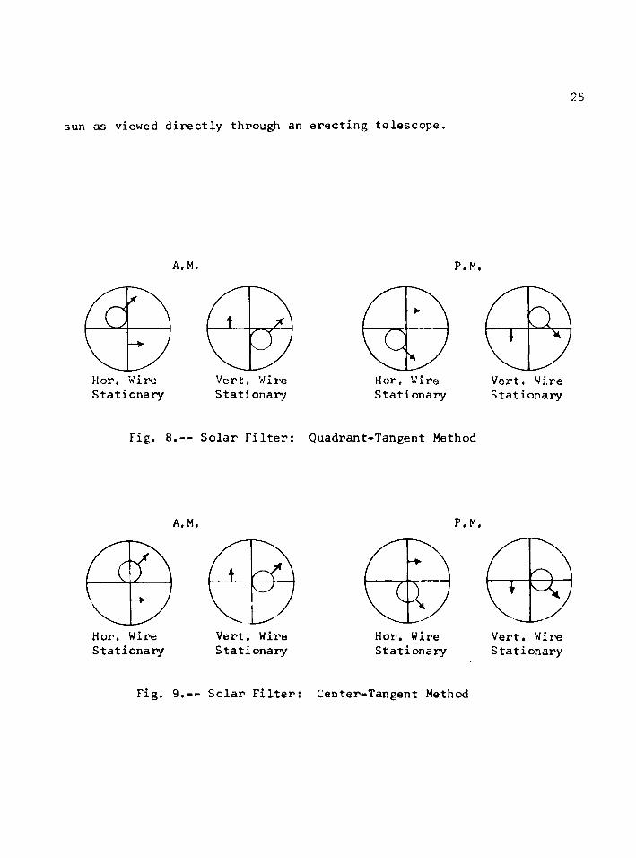
sun as viewed directly through an erecting telescope.
25
A.M.
Hor. W i re Stationary
Vert. Wire Stationary
P.M.
Hor, Wire Stationary
Vert. Wire Stationary
Fig. 8.— Solar Filter: Quadrant-Tangent Method
A.M.
Hor. Wire Stationary
Vert. Wire Stationary
PP.
Hor. Wire Stationary
Vert. Wire Stationary
Fig, 9.— Solar Filter: Center-Tangent Method

26
Solar Reticle!
The precision of sighting the sun's center, either by use of
a solar screen or a darkener, can be increased by use of a solar
reticle.
A solar reticle is similar to the reticle in any transit in
that it contains a vertical and horizontal wire. It also contains
stadia hairs and is manufactured with a stadia ratio of either 1:100
or 1:132. The added feature is that it contains a solar circle equal
to the image of the sun's diameter. A solar reticle with a stadia
ratio of 1:100 is shown in fig. 10.
Fig. 10.— Solar Reticle
The solar circle has a radius of 15'-45". This is equal to
the sun’s semidiameter when it is at a minimum approximately July 1.
The sun's image can be centered very accurately by superimposing the
circle over the image of the sun. The Bureau of Land Management in
the Manual of Instructions For The Survey of The Public Lands of The
United States 1947, described this advantage of the solar reticle.

"The manipulation of the vertical and horizontal tangent-motions to
the position of concentric fitting, of the circle to the sun's image
may be accomplished with utmost certainty that the values for the
vertical and horizontal angles are exactly simultaneous,"
The use of the solar reticle offers several other advantages.
Observations are faster and both horizontal and vertical angles -are
read to the sun’s center. Unlike the quadrant-tangent method, there
is no difficulty in selecting the correct quadrant or using a stadia
line by mistake. Any single reading may be reduced separately without
a correction for semidiameter. In the event of a suspected misreading
of an angle, the difference between the several sightings, in travel
timeve r t i c a l angle, and horizontal angle, which should be propor
tional, may be quickly checked.
Simplex Solar Shield
Professor C, H, Wall of Ohio State University developed a
shield to be used for pointing at the center of the sun. It consists
of a perforated shield which is mounted between the eyepiece of the
transit and a solar screen. The perforations and other sighting
points are so arranged that when a selected pair of these points are
brought tangent to the sun's image, the center of the sun's image is
^Bureau of Land Management, Manual of Instructions For The Survey of The Public Lands of The Unite'd States ,"page 1301

28
on the horizontal or vertical crosshair» Davis and Foote9 in their
well known surveying textbook, show a diagram of successive positions
of the s m V s image with relation to the Simplex solar shield e
An effort was made to obtain a Simplex solar shield to compare
the accuracy of pointing with other methods» Neither Carl Fti Purtz
of the Civil Engineering Department g Ohio State University s or
Mrs6 Co Ho Wall, wife of the late Professor Wall* could give any
information concerning their manufacture or use®
Roelofs9 Solar Prism
One of the most recent and refined methods of pointing on the
sun was introduced by Professor R 0 Roelofs of the Technical University
of Delft 9 Holland* It consists of an attachment that fits over the
objective lens of the telescope 6 The attachment contains a series of
prisms that when pointed at the sun produces four images of the sun«
The overlapping images form a bright cross with a small dark square
at the center. Fig, 11 shows this image as seen through a telescope*
^Davis and Foote * op.cit,* page 520

29
Fig, 11.— Reelofs’ Solar Prism
The Roelofs* prism offers several advantages over other
methods of pointing on the sun.
1. The prism contains filters which produce monochromatic
green images of the sun which are comfortable to the observer's
eye and reduce the sunlight and heat which enter the telescope.
When using any other method of pointing a telescope at the sun,
the objective lens acts as a burning glass and causes extreme
heating of the reticle. This heating may result in an irregular
expansion of the crosshairs and an error will occur in both the
vertical and horizontal angles.
2. There is no confusion as to the choice of the quadrant

30
or correction necessary for s@midiameter«
3e The overlapping images provide a better target and result
in a more accurate pointing0
In Professor Roelofs9 book, Astronomy Applied to Landaaacraar ■ -iit c-Tirt i:. .rj sm m rwi&MJS n j=r. —iZaxriX zaJK1:. r T r r v - t 3gf?y,-tcu»«e;c«tt=»“»
g he states that a correction is necessary for the eccentri-
is no longer necessary when using the prism as manufactured at the
present times Wild Beerbrugg Instruments9 Inc, obtained the sole
manufacture rights, and made a minor modificatione Correspondence
with the Wild Beerbrugg Company resulted in the following explanatione
After Professor Roelofs turned over his prism idea toWILD for fabrication * we found there is an easy way to bypass, the eccentricity in pointing by inserting another wedge over the whole objective, That third wedge is tinted and serves as a sun filter at the same time. This wedge reflects the centre point of the four sun imagesback to the centre of the telescopec Actually in the WILD solar prism the centering wedge consists of two (one in front of the half wedges according to Roelofs and another behind if) for easier adjustment in the fabrication.
1R. Roelofs s, Astronomy Applied to Land Surveyinga N» V, Wed. J, Ahrend 6 Zoon9 Amsterdam9 Holland, 1950, page 70.
city of pointing when using the Roelofs’ prism.^ This correction

CHAPTER IV
CORRECTIONS FOR THE SUN'S
CURVATURE AND SEMIDIAMETER
Semidiameter
The sun's angular semidiameter is defined as the angle subtended
at the earth's center by the sun's radius. Fig. 12 shows this rela
tionship.
SunEarth
Fig. 12.— Semidiameter Correction
The semidiameter (S) can be expressed as
rsin S = —P
where
r = mean radius of the sun
and
p = distance from the earth's center to the sun's center.
31

32
Since the path of the earth8s orbit is elliptical the distance
p is constantly changing* This is reflected in the value of S* The
range of S is between 158”45" and 168-17"e The exact value is given
in the solar ephemeris*
The ephemeris published by the Bureau of Land Management
tabulates the value of S ’at Greenwich apparent noon for each day of
the year. The value is given to the nearest hundredth second*
The Keuffel and Esser solar ephemeris lists the semidiameter
for every ten days to the hundredth minute. The maximum change in
any ten day period is three seconds.
The Gurley ephemeris gives the value of S to the nearest
second for the first day of each month. The maximum change in
semidiameter in any month is eight seconds, Straightline inter
polation will give a value sufficiently accurate for all but the most
precise survey work.
Correction to Vertical Angles
Vertical angles turned to sun9s upper or lower limb must be
corrected for semidiameter» This correction is simply the tabulated
semidiameter as taken from the ephemeris.
Correction to Horizontal Angles
The correction to a horizontal angle turned to the sun9s
limb is a function of the sun8s altitude. The relationship between
the sun's semidiameter and altitude is shown in Fig, 13*

33
North
A B
South
Fig. 13,— Horizontal Angle Correction for Sun's Angular Semidiameter
The zenith distance (z) is by definition equal to 90°-h.
The law of sines applied to the right triangle formed by the
center of the sun, the edge of the sun, and the zenith gives
sin A B _ sin 90° sin S sin z
or
sin A B = sJ Ll............................................. (9)sin z
Eq. (9) can be simplified by the assumption that the sin of a
small angle is equal to the angle expressed in radians. Since the con

34
version factor for radians will cancel9 the correction to horizontal
angles for semidiameter expressed in the -same unit as S is equal to
B ~ t S x esc z
or
B •** g,,, S X SeC h eoeeeeseeoeeodeeoeeoeosoeGeeAooeeeeeecee C 10 )
Curvature Correction
The authors of most surveying texts dealing with astronomical
measurements recognize the error in assuming the path of the sun is a
straight lineo They frequently place some time limitation on how
long a series of observations may extend when using the mean hori
zontal and vertical angles of such a series• There is little agree
ment as to the length of time the sun*s path may be assumed straight
without introducing significant error* A time limitation of ten
minutes is probably the most frequently used, ^*2*3
The effect of using the average horizontal and vertical angles
of a series of observations is shown in Fig, 14, For simplicity, only
two positions'of the sun are shown,
^Bureau of Land Management § Manual of •Instructions for the Survey of The Public Lands of The United Statesg 19479 U, S 6 Government Printing Office $> page 528,
^Charles B, Breeds Surveying& John Wiley and Sons* Inc* 9 New York * 19429 page 141*
^Geologic Survey9 Topographic Instructions Solar Observations for Transit Traverse» Government Printing Office % 1953* page 9 &

3S
Horizon
Fig. 14,-- Effect of Curvature
Point (a) represents the average horizontal pointing on the
sun. The corresponding average altitude (h) is then used to compute
the sun's azimuth. This results in a computed azimuth (B) to point
(b). The difference (C) is known as the curvature error.
Paul Hartman, in a recent paper published by the American
Society of Civil Engineers, investigated the magnitude of this error
and derived a formula for curvature correction.^ The equation is
^Paul Hartman, "Solar-Altitude Azimuth", Journal of the Surveying and Mapping Division, ASCE, Vol. 89, No. SU1, Proc, Paper 3410, February, 1963.

This formidable appearing equation is solved by parts using
a slide rule and tables. The first expression
A - la-n- P. H — x (1 ♦ COS2 B) dh2 sin B
2 2 2 (tan Phi. + tan h) _ sec h (12)tan B x sin B tan B
and the second term
dh _ cos Phi, x sin t x cos Dec. .............. (13)dt cos h
are solved by slide rule. The last term
i lAt (14)
is computed by use of a table. The most complete table is found in
Special Publication 14, of the U. S. Coast and Geodetic Survey.
When (B) is the azimuth of the sun measured from the north, east
in the A.M. and west in the P.M. , the curvature correction (C) should
always be added tc the value of (B) computed from the mean altitude (h).
Semidiameter Correction
The semidiameter correction applies only to solar observations
where the quadrant-tangent method of pointing is used. Fig. 15 shows
the effect of using the average of two horizontal angles turned to
the sun’s limb.
Point (a) represents the bisector of the sun’s centers. Point

37
(b) is the bisector of the sun's limbs. The two points do not coincide
since S x secant h^^zf S x secant h^. This error is known as semi
diameter error.
•HrV
HorizonM
Fig, 15.— Effect of Semidiameter
Paul Hartman also derived a correction factor to be used for
semidiameter.^ This factor (Cr) is obtained by solving the following
equation.
Cr = ~ [0.127 x h x 105 + 0.322 x h 3 x 10⁹ +
0.60 x h5 x 1013 + 0.99 x h7 x 1017] ^ | At | (15)
^Ibid., page 12.

38
In this equation
S = sun’s semidiameter in seconds
n = number of telescope pointings
h ~ sun’s altitude in degrees
t = difference of individual times of pointing from the
mean time*
The expression dh/dt is given in Eq» (13)*
Hartman states that this equation should be solved by slide
rule® For values of (h) less than 30° only the first two terms inside
the brackets are used* When (h) is less than 40° the first three
terms are used*
The correction (Cr) should be added to the mean clockwise angle
for an A.M* observation and subtracted for a P.M, observation if the
west limb of the sun is used for the initial sighting*
Application
When using the quadrant"tangent method of pointing the effect
of curvature error and semidiameter error tend to cancel one another
provided the observing quadrants are properly chosen» Fig* 16 shows
the sun as viewed directly through an erecting telescope in the
correct quadrants *
In the northern hemisphere the first telescope position of a
pair of pointings is that one which requires the sighting of the west
limb of the sun * By observing9 in this manners the horizontal and
vertical angles in the direct position, of the telescope will have
approximately the same values as in the reversed position of the

39
telescope. This results from the movement of the sun during the time
taken to plunge the telescope and make a second sighting. The semi
diameter error and curvature error are a minimum when the corresponding
angles in the direct and reversed positions of the telescope are about
the same.
A.M. P.M.
Fig. 16.— Quadrant-Tangent
The above method of pointing differs from that shown in
Fig. 8. Pointing as illustrated in Fig. 16 involves tracking the
sun with both the horizontal and vertical motions of the transit.
The curvature and semidiameter error are kept at a minimum only by
sacrificing the accuracy of pointing.
Curvature and semidiamcter corrections must be made if
accurate azimuths are to be determined. If high accuracy is desired
the altitude method should not be used. When the altitude method is
used there are several ways to overcome the effect of both curvature

and semidiameter error0
The semidiameter.error will.not exist if pointings are made ■
on the sun9s center* This can be accomplished by a number of devices
as pointed out in Chapter III* If pointings are made on the sun ?s
limb then each pointing should be corrected to the s m V s center*
This not only eliminates semidiameter error, but also provides a means
of spotting a misreading of an angle or a poor pointing*
Curvature correction is unnecessary if each observation is
used independently to compute azimuth*
When using the quadrant-tangent method of pointing the average
of each pair of observations taken in diagonally opposed quadrants
should be used to compute azimuth * The time duration will be so
short and the vertical angles so nearly equal that any correction
can be safely neglected*
Consistent azimuth determination by use of the altitude method
demands a low dB/dh value* The corrections for curvature and semi
diameter are relatively unimportant when the dB/dh ratio is one or
less *
One apparent advantage of the curvature correction is in
building up the horizontal angles * An engineer’s transit reading
only to one minute could be used to measure the horizontal angle to
the sun’s center within 10 or 15 seconds if sufficient repetitions
were made * The curvature correction could then be applied to the
azimuth computed by using the- mean altitude (h) 0 This apparent
advantage is lost when it is realized that the computed azimuth is

dependent on the mean altitude» Regardless of the number of
repetitions the vertical angle to the sun9s centers using a one
minute transit % will be no better than one minute
^Winfield H e Eldridge§ "Discussion of Solar-Altitude Azimuth" Proceedings of the Surveying and Mapping Division, No* 3410§ ASCE§ Oct., 1963% ^

CHAPTER V
DETERMINING DECLINATION, LATITUDE,
AND LONGITUDE
Declination
Declination has already been defined as the astronomical
position of the sun north or south of the celestial equator* Dec
lination is independent of the observer's position as, at any
particular instant, it is the same to all observers in all parts of
the world*
The values of the sun9s declination for any given day are
published in the ephemeris* The word ephemeris is of greek origin
meaning diary or calendar* It contains the computed astronomical
positions of Polaris, the sun s and a number of major stars for every
day of the year.
The ephemerides published each year by the surveying instru
ment manufacturers, such as Keuffel £ Esser and W. £ L. E. Gurley,
give the sun's declination for 0 hour Greenwich Civil Time. This is
the most convenient form for the present day surveyor who determines
time by a radio time signal* Stations such as WWV give the civil
time, and knowing the time zone, the Greenwich Civil Time can be
easily found.
Before the event of wide usage of the radio, it was customary
* 42

43
to determine time by an altitude observation of the sun* The time so
determined was Apparent Time* In this case, it was more convenient
if the declination was given for Greenwich Apparent Noon or 0 hour
Greenwich Apparent Time* This is also the case when a solar
attachment is used and the hour angle must be set off in local
Apparent Time, Since the Bureau of Land Management uses the telescopic
solar transit extensively in its work* the ephemeris published by them
gives the sun9s declination for Greenwich Apparent Noon,^
Declination as listed in an ephemeris is called apparent
declination* This means the declination of the sun is measured from
the true celestial equator* Apparent coordinates include all the
effects of proper motion* luni-solar and planetary precession*
nutation* and aberration* It is the apparent coordinates of the sun
that a land-surveyor must use in the astronomical determination of
latitude* longitude* and azimuth.
In all American ephemerides it is the practice to give the
change in declination per hour, Plate 1 is a sample form used in the
computation of declination. It is to be used when the sun93 dec
lination is listed for 0 hour Greenwich Civil Time and the rate of
change in declination per hour is given. The use of such a form saves
time and prevents errors for those surveyors who take solar shots
infrequently,
^United States Department of the Interior* Bureau of Land Management* Ephemeris of The Sun* Polaris* and Other Selected Stars* United States Governme'nt Printing 0ffice»

44Plate 1
COMPUTATION OF SUN’S DECLINATION
Watch time of observation
Watch error**- .,o e e o e e e e o o e e o o o e i e o e o o e e e o e Q p e B o e Q
Standard time of observation2
o e o o o o o o e o
Longitude of central meridian
Total time since 0 Greenwich
Total hours since 0 Greenwich
o e f r o e y f f p o e e o e e o i
e e o e c e o B e
hr.
Jir._
_hr.
Jir«=
hr.
min.
mm,
mm,
_sec.
sec.
sec.
sec.
Apparent Dec. for 0 Greenwich =« © e e e e e o o o e o e o
TfotaX hours) (Change in Dec./HrT)^
S lin S DG C Imatl on eeeeeeeoeoBeeoeeooeeo
^Watch error by comparison with radio time signal* Add difference if watch is slow and subtract difference if watch is fast<
^Longitude of central meridian expressed in time west of Greenwichi
Eastern Standard Time „,..»,„. 75 meridian *.* *« 5 hreCentral Standard Time «0 ©*«>©© s 90 meridian Q Q»»© 6 hr eMountain Standard Time ....... 105 meridian ..... 7 hr.Pacific Standard Time ........120 meridian ..... 8 hr0
^Sign as given in Ephemeris,

When using a solar attachment * the sun9s declination corrected
for refraction in polar distance9 is usually computed or plotted in
advance* The value of the sun*s refraction is added algebraically
to the tabular declination. Therefore9 it will increase north or
plus declination and decrease south or minus declinations,
. Plate 2 is an example of one method of plotting a declination
curve to be used with the solar attachment* The straight line is the
declination as taken from an ephemeris with a slope equal to the rate
of change in declination per hour* The curved line is the declination
corrected for refractiono The corrections for refraction are a
function of the altitude of the sun* They can be taken directly from
tables using an argument of declination* latitude* and hour angle*^
When an observation is to be taken* the time is observed and the
corrected declination taken directly from the graph.
The effect of errors in declination on the computed azimuth
will be covered in Chapter VIe
Latitude
Latitude is the angle between the direction of the plumb line
and the plane of the earth*s equator* Latitude is positive when
^United States Department of The Interior* Bureau of Land Management* Standard Field Tables, U, S, Government Printing Office, Washington 25 * D, C,

— I :r T*
T 4 —
4__ Tei
e s c o p i
^ I ait e __2 i' ~i
— j— —|
c . S o I dr becUnat l ion ; S e t t i n g 46
March,a; I 9 e 4 Ph i,= 3 2° -15
, S6°’5 0
US-7 i OO
M. Sv T.

47
measured north and negative when measured south of the equator.
In the United States, latitude can be scaled from a U.S.G.S.
7 1/2 minute quadrangle of 1:24,000 scale with an uncertainty of not
more than * one second. This is based on the following reasoning:
Standard map accuracy for horizontal control requires that the
map position of 90% of checked points be within 1/40 of an inch and
that the other 10% be within 1/20 of an inch of their true positions.
Referring to Fig.17 and using the mean radius of the earth as
3,959 miles the coverage of a 7 1/2 minute quadrangle can be found.
Pcle
PhiEquator
3,959 mi
Fig. 17.— Accuracy of Measuring Latitude

4 8
2 x 3.14 x R - X or X = 8.637 miles 360 x 60 7.5'
Therefore, at a scale of 1:24,000, the length of a 7 1/2' quadrangle
would be:
■?.16.32. *. z 22.80 inches24 ,000
This would mean that any position that can be located within 1/20 of
an inch on the map represents the following length of arc.
22.80 in. _ 1/20 in.7.5 x 60 X
X = 0.99 seconds
On a 15 minute quadrangle with a scale of 1:62,500 the above reasoning
results in a maximum error of t 2,6 seconds.The effect of an error in latitude on the computed azimuth
will be considered in Chapter VI.
Longitude
Longitude can be defined as the angular distance measured
along the equator from a fixed meridian to the meridian of the obser
ver. The fixed meridian is usually considered as that meridian through
Greenwich, England, and longitude is considered positive when reckoned
westward from that point.
The accuracy of determining the longitude of an instrument
station by scaling from a map is dependent on the latitude of that
station. For a given scale map the closer the station is to the
equator the more accurate longitude can be determined.

49
Excluding Alaska the maximum error in longitude in the United
States , obtained by scaling from a U.S.G.S. map, would occur at a
latitude of 49°, The magnitude of this error can be computed by
referring to Fig. 18,
Pole
Phi Equator
Fig. 18.— Accuracy of Measuring Longitude
The circumference (Cir.) of the earth at a latitude of 49°
equals
2 x 3.14 x r
Using the mean radius of the earth (R) as 3,959 miles and substituting
for r
Cir. = 2 x 3.14 x R x cos 49° = 16,312.3 miles
The coverage of a 7 1/2 minute quadrangle (X) would be

50
X _ 16,312.37.5 360 x 60
X = 5.66 miles
At a scale of 1:24,000 the length of this quadrangle would be
= 14.9 inches24,000
If a position can be located on the quadrangle to an accuracy of 1/20
of an inch then the resulting error in longitude (L) would be
L _ 7.5 x 60 .05 “ 14.9
or
L = 1.51 seconds
The same reasoning will result in a maximum error of 1.17 seconds at
Tucson, using a latitude of 32°-151.
If the procedure is repeated for a 151 minute quadrangle at a
scale of 1: 62,500 the following results are obtained.
Latitude Error in Longitude from Scaling
32°-15’ ------------------------ 3.08 seconds
49°-----— — — — — — — — — 3.95 seconds
When determining azimuth by the altitude method there is no
need to measure longitude. On the other hand use of the hour angle
method requires the accurate measurement of longitude. The time of
the observation together with the longitude of the station are used to
compute the local hour angle. The effect of an error in hour angle
on the bearing of the sun will be considered in Chapter VII,

CHAPTER VI
AZIMUTH BY THE ALTITUDE OF THE SUN
Introduction
The determination of azimuth by the altitude of the sun is the
most commonly used method in the United States. Unlike the hour angle
method it does not require an accurate measurement of time. Survey
ing textbooks and solar ephemerides published annually by instrument
manufacturers explain this method in detail. The civil engineering
student may hear of other methods of determining azimuth by solar
observation, but it is highly probable that in his college course
work, the altitude method is the only one he will use.
Trigonometric Formulas
The basic equation for the solution of the astronomical tri
angle when the altitude is known was derived in Chapter II. It will be
repeated here along with a number of other equations used in the
altitude method. The equations, though different in appearance, are
basically the same. All equations require knowing the latitude of the
station and the altitude and declination of the sun.

52
cos B s ..... A^.n Dec* ^ .. tan h x tan Phi............... (17)cos h x cos Phi.
tan2 1/2 B = sin(s-h) x sin(s-Phi.)........................ (18)cos s x cos(s-p)
sec 2 1/2 B = (19)sec h x sec Phi.
vers B = sec Phi. x sec h [vers p - vers(Phi.-h)] ..... (20)
Each term in Eq. (5) has already been defined. The value of
(h) used in this equation and all equations involving the sun’s alti
tude must be corrected for refraction and parallax. In Eq. (5)
azimuth is measured from the north. If the observation was taken in
the morning the bearing is east of north, if taken in the afternoon
west of north. When a minus value results from the solution of Eq. (5)
azimuth is measured from the south, east in the A.M., and west in the
P.M.
Eq. (16) is identical with Eq. (5) with the exception of the
sign. In this case a positive sign indicates the azimuth is measured
from the south, and a negative sign means the azimuth is measured from
the north. Again it is measured east in the A.M. and west in the P.M.
Dividing each term in the numerator of Eq, (5) by cos h x
cos Phi. results in Eq. (17).
An interesting variation of Eq. (17) was derived by Philip
Inch.^ Starting with
cos B = Sj-P. --- tan h x tan Phi. ........... (17)cos h x cos Phi.
^Tnch, op.cit., page 971

The resulting equation was
cos B = A x sin Dec. - B ................... ............. (21)
Tables were then arranged using arguments of (h) and (Phi.).
Values of (h) from 15° to 55° were plotted against values of (Phi.)
from 31° to 49°. Values of (A) and (B) could be taken directly from
the tables. The tables included correction for refraction and
parallax.
Eq. (18) is an application of the half angle formula to Eq.(5).
A step by step derivation can be found in most texts of spherical
trigonometry.* The polar distance (p) = 90° - Dec. and s = l/2(p + h
+ Phi.) are used for the first time in this equation.
Eq. (19) is similar to Eq. (18) but involves only one trig
onometric function, the secant. It was derived by T. F. Nickerson
by a number of substitutions in the basic half angle formula for
cos B/2. Eq. (19) has two advantages over any of the other altitude
^William L. Hart, College Trigonometry, D. C. Heath and Company, Boston, Mass., 1951, page 193.
^T. F. Nickerson, Determination of Position and Azimuth by Simple and Accurate Methods, Transactions of A&CE, Vol. 114, 1949, page 143.

54
equations« It deals entirely with one function and in case logarithms
are used the characteristics will always be positive. Plate 3 is a
sample form to be used in computing azimuth by Eq. (19). The form is
patterned after that of Hickerson in his book* Latitude* Longitude* and
Azimuth by The Sun or S t a r s A table of log secants is used and the
solution requires no multiplication. To those who use logarithms
- infrequently the use of such a form, saves both time and costly errors,
Eq, (20) makes use of the versed sine (1 minus the cosine). By
exchanging the polar distance (p) for 90°- Dec, and use of the double
angle formula it reduces to Eq. (5).
Factors Affecting The Measuring of Altitude
The altitude method of solar observation is directly dependent
on how good the vertical angle can be measured to the sun’s center.
There are a number of factors that can contribute to incorrect vertical
angles. These factors will be considered"in the following paragraphs, -
Instrument Error
The first source of error would be in the adjustment of the
instrument. There are three major conditions that result in erroneous
vertical angles.
1. The vertical axis out of plumb.
^T. F. Hickerson„ Latitude* Longitude* and Azimuth by The Sun or Stars * published by the Authora Chapel Hill* N.C, 9 1947* page 40,

Add
55
Plate 3
DETERMINATION OF AZIMUTH By Use of Log Secants
Sec. 2 l/2 B =
B = Horizontal angle from north reckoned east in A.M. and west in P.M.
P = 90o-Dec.
S = 1/2(P + h + Phi.)
89°- 59'- 60"
'O"O<
Dec.
P =
h =
Phi. = r-
28 =
S =
S-P =
S—h =
Alg. Sum
Subtract
Log Sec. x 10'
Subtract
= Phi. (check)
1i
qT3XI<
1/2 Z =
Z =
^North Dec. is + and is subtracted. South Dec. is - and is added.

56
2» A lack of parallelism between the line of sight and the
axis of the telescope level,
3<> The displacement of the vertical vernier from its adjusted
position.
The first condition,.inclination of the vertical axis, is the
most serious. Unlike the other two sources of instrumental error$ it
cannot be eliminated by observational procedure. It can be reduced to
a negligible amount by careful leveling of the transit.
The most exact method of leveling a transit is by use of the
telescope bubble. The procedure is as follows: After the instrument
is leveled using the plate bubbles a the telescope is brought over a
pair of leveling screws with the (A) vernier set to 0°, Center the
telescope bubble by using the vertical clamp and tangent screw. The
upper motion is released and the telescope rotated 180° as shown by the
reading on the (A) vernier. If the telescope bubble is not centered»
bring it halfway to the center by use of the vertical tangent screw
and the remaining way by using the two leveling screws. The upper
motion is released and the telescope rotated to its initial position.
The telescope bubble should remain centered. If it does not 8 repeat
the process of bringing it halfway to the center by use of the tangent
screw and the remaining way by use of the two leveling screws. When
the bubble remains centered at both 0 ° and 180° the telescope is
rotated until the (A) vernier reads 90° or 270°, This places the
telescope in line with the other pair of leveling screws. The

57
telescope bubble is now centered by use of the leveling screws only.
This completes the operation and makes the vertical axis of the
transit truly vertical.
The error resulting from measuring a vertical angle when the
transit has not been carefully leveled is shown in Fig. 19.
Angle (H) is the angle of inclination of the vertical axis.
The axis lies in a vertical plane that deviates from the vertical
plane containing the sun by the angle (Z). The error in the measured
vertical angle is equal to (H) when (Z) = 0 ° and 0° when (Z) = 90°.
Sun
Fig. 19.— Instrument Error

58
The angle (H) can be accurately measured by means of the tele
scope bubble« The sensitivity of the bubble is the angle of inclina
tion in seconds of arc per division of bubble run« This means that
when using an Engineer’s transit, with a telescope bubble having a
sensitivity of 60 secondse the displacement of the bubble by one-half
of a division could result in an error of 30 seconds in the vertical
angle.
The second and third condition can be corrected by adjustment
of the transit or eliminated by the observational procedure.
The adjustment for a lack of parallelism between the line of
sight and the axis of the telescope level is known as the peg adjust
ment. It is explained in detail in any surveying textbook or instru
ment manual.
The Vertical vernier can be checked for adjustment after the
instrument has been carefully leveled using the telescope bubble.
When the bubble is centered, the vertical angle should be 0 °, If it
is not the vernier is loosened and moved until the correct reading is
obtained.
The error resulting from a lack of parallelism between the
line of sight and the axis of the telescope level, or from displace
ment of the vertical-circle vernier, or a combination of the two,.is
known as index error. Adjustment for index error is unnecessary if
the transit has a full vertical circle. When the vertical axis of
the transit is truly vertical, the mean of two vertical angles, one

59
taken with the telescope direct and the other with the telescope
reversed 9 is free from index error.
Another possible source of error would be imperfections in the
manufacture of the instrument. Such things as eccentricity and
imperfect graduations are relatively unimportant in a modern transit
in good adjustment and can be ignored in all but the most precise work.
The magnitude of the instrument error is almost completely
dependent on how carefully the transit has been leveled when using
correct procedure in measuring a vertical angle.
Refraction
As light travels from the sun to the earth, it passes from
the empty interstellar space into the earth’s atmosphere. As the
height above the earth's surface diminishes„ the density and tempera
ture of the air increases. This results in the ray of light being
bent vertically downward. There are a number of equations that have
been derived to correct for this phenomenon. The basic equations are
based on a number of assumptions. It is assumed that the atmosphere
is built up of an infinite number of infinitely thin spherical layers
concentrical with the earth, and each having a uniform refractive
index throughout.
An equation can be derived by ignoring the curvature of the
layers and assuming the number and thickness to be finite. Applying
Snell's Law of refraction to Fig. 2 0 * the following equation can be
written.

60
Earth’s Surface
Fig. 2 0 ,— Refraction
sin Z,, U 3
7n r r 3 * unIn this equation (U) is the index of refraction and in the case
of a vacuum is equal.to 1. Therefore,
t sin Zn = sin Z 3 x U 3 ....................................... (22)
If Snell's Law is applied to the succeeding layers the following
equations can be written:
U3 x sin Z 3 = U2 x sin Zg
U 2 x sin Z 2 = Ujl x sin Z^
by substitution Eq. (22) becomes
sin zn ° x sin Z ^ ............................... ........ (23)

Clsince
refraction (r) = Zfi -
or
zn = zx + r
Eq. (23) becomes
sin (Z^ + r) = x sin Z^ ........................... (24)
Expanding Eq. (24) by use of the addition formula results in
sin Z jl x cos r + cos Z^ x sin r = x sin Z^
Since (r) is a small angle, usually less than 35 minutes, the cosine
of (r) is approximately one. Therefore,
sin Z^ t cos Zjl x sin r = x sin Zj If refraction (r) is expressed in radians then for a small angle sin r
is approximately equal to (r). Then
sin Z jl + cos Z jl x r = Ui x sin Z^
or
r = tan Zjj x (U^ - 1) ...................... (25)
It should be noted that in this formula that only the index
of refraction for the lowest layer appears. This equation gives good
results when the zenith distances are so small that the assumption of
horizontal planes is reasonably correct.
An empirical equation has been derived by Comstock that gives
a closer approximation.^
^Nassau, op.cit., page 66,

62
r - H H t x tan z / ..................................... (26)
where
r = refraction in seconds of arc.
b = barometric pressure in inches,
t = temperature in degrees Fahrenheit.
= observed zenith distance.
According to Nassau, for zenith distances under 75°, Eq. (26)
should give the refraction within one second.
A number of tables are available that list the mean refraction
and give both temperature and pressure corrections. Two of the most
complete tables are found in U.S.C. & G.S. Special Publication No. 247i oand in Seven Place Logarithmic Tables by Von Vega. »
When solar observations are taken with a one minute transit
the surveyor should not be overly concerned with the temperature and
barometric pressure corrections to the tabulated refraction. Unless
observations are made at extreme temperatures and at high elevations
the corrections are relatively unimportant. Host of the azimuth
determinations in the United States are made at an elevation between
sea level and 2000 ft. and temperatures between 0 ° and 100° Fahren
heit. This would result in a maximum error of 18 seconds if correc-
^U. S. Coast and Geodetic Survey, Special Publication No. 247, Government Printing Office, Washington 25, D. C., Tables 25, 26, and 27.
^Baron Von Vega, Seven Place Logarithmic Tables, D. Van Nostrand Company, Inc., Princeton, New Jersey.

tions were ignored for an altitude observation of 15°.
The correction for refraction is always subtracted from the
observed altitude.
One of the most common sources of error in computing refrac
tion is due to a local variation in temperature and pressure. This
variation can be caused by the close proximity of lakes, forests, or
buiIdings.
Parallax
Parallax is the correction to the observed zenith distance
to the sun, measured from a point on the earth's surface, necessary
to represent the zenith distance from the earth's center. The
parallax of the sun for any observed zenith distance can be obtained
by referring to Fig. 21.
S u nH o r i z o n
Fig. 21.— Parallax

64
By the Law of Sines
sin p _ sin (180° - %/)" R “•----------d..... ................................... (27)
where
= observed zenith distance
R = radius of the earth
p = sun's parallax
d = distance of sun from the center of the earth
Again referring to Fig. 21 the horizontal parallax (p) is equal to:
sin p/ = £ ..................... (28)d
From Eq, (27)
sin p = ~ x (sin 180° x cos - cos 180° x sin Z^) dor
R /sin p = — x sin Z' d
substituting the value of R/d from Eq. (28) gives
sin p = sin p/ x sin Z ^ .......... (29)
The horizontal parallax of the sun is given in the American
Ephemeris for each day of the year. It has a maximum value of 8.95
seconds and a minimum value of 8 . 6 6 seconds. This gives an average
value of 8.80 seconds. In place of computing the sun's parallax by
Eq. (29) a satisfactory expression can be obtained as follows. Using
the average value of the sun's horizontal parallax and realizing that
the value of (p) will always be less than p / , an approximate solution

65
to Eq. (29) can be written
p = 8.80 sin ...... (30)
The parallax correction is added to the vertical angle to
correct the altitude observation to the center of the earth.
Altitude Correction for Semidiameter
If in making a solar observation the limb or edge of the sun
is observed, the vertical angle must be corrected to the center of
the sun. If the upper limb of the sun is used, the semidiameter is
subtracted from the altitude. If the lower limb is observed, the
semidiameter is added to the altitude.
The sun's semidiameter is dependent on the distance between the
sun and the earth. This distance is constantly changing due to the
ellipticity of the earth's orbit around the sun. The semidiameter
is tabulated in the solar ephemeris for each day of the year.
Effect of Errors in Altitude on the Computed Azimuth
The equation most frequently used to compute the sun's azimuth
by the altitude method was derived in Chapter II. This equation
n - sin Dec. - sin h x sin Phi. , c\cos ti - .... —■ ■ v” .............I,— lb;cos h x cos Phi.
can be differentiated with respect to (h) holding (Dec.) and (Phi.)
constant. After simplifying the equation becomes
dB tan Phi. - tan h x cos B ,dFT ----------- sTiTB........... ............................. (31)

66
As the sun's bearing approaches the meridian at noon the value of (B) will approach 90° and an error in altitude will have the greatest
effect on the computed azimuths
Since the measured altitude to the sun’s center is subject to
a number of factors that may introduce error, the dB/dh ratio is
probably the most important criterion as to the accuracy of the
altitude method. Inspection of the dB/dh ratio will tell the surveyor
the possible error in a computed azimuth for a given probable error in
the measured altitude, <
The dB/dh ratio can be obtained at the time of the observation
by comparing the difference in two horizontal angles to the sun’s
center with the difference between two corresponding vertical angles
to the sun’s center, A more useful method would be one that would
tell the surveyor at what time, on any given date, he must take an
observation to obtain a desired dB/dh ratio. This can be accomplished
by means of an altitude-azimuth curve.
Inspection of Eq, (31) shows that the dB/dh ratio is dependent
on the latitude of the observing station. Sufficiently accurate
altitude-azimuth curves can be developed by using the latitude of a
central station in the area of interest.
The curves can be developed by either of two methods, Eq, (5)
can be solved for (B) by assuming different values of (h) for a given
declination and latitude. An easier method is by the use of prepared

tables that give the values of (B) for a given (h), (Phi.), andX(Dec.). If tables are used the hour angle is also given and may be
plotted together with the altitude and azimuth. Eq. (31) is then
solved for different values of dB/dh and the results plotted on the
altitude-azimuth curves. Plate 4 is an example of the altitude-
azimuth curves for Tucson, Arizona, with both hour angle and dB/dh
curves superimposed.
Once such curves have been developed for a particular area,
limits can be established on when observations should be taken. For
example, a limiting value of the dB/dh ratio equal to 1.5 would be
reasonable at Tucson, This would assure consistent results and at
no time require an altitude measurement less than 2 0 °»
Effect of Errors in Declination on the
Computed Azimuth< niri—B" m..., /T
When the altitude method of determining azimuth is employed,
the only reason for observing the time is in the computation of dec
lination, The maximum change in declination per hour is approximately,
sixty seconds. This means that for the most accurate work, a deter
mination of time within two minutes would result in an error no
larger than two seconds in declination. When taking a solar shot with
• Tables of Computed Altitude and Azimuth, Hydrographic Office P u b l i c a t i ^ % o r ° ° ^ T ^ T ° W ^ T % a % y T ^ T ? T ° ^ ^ % S e n t Printing Office, Washington, D. C. „

akljTUDE-AzlM UTh
Tucson, Arizona
r r - B 'm m g ^ d f ' S u f T l f r 6 hii“ ]Squ™f>i r ' E ijsT T n STM': v \W e s T Tn"“R'Tff
I ; i : i . :• • • • ; I • ' ' I t • . ' ! • .. • I ... • .

an engineer’s transit, with horizontal and vertical verniers reading
to one minute, and the rate of change in the sun’s declination an
average value of 25 seconds per hour, a determination of time within
twenty minutes is normally sufficient. The effect of an error in
declination on the computed azimuth can be determined for any latitude
Deferentiating the altitude Eq. (5) and holding (Phi.) and (h)
constant results in the following expression.
dB _ cos Dec. (32)dDec sin B x cos k x cos Hii. .... .
The above equation was solved for a latitude of 32°-15’ with
the aid of the altitude-azimuth curves. Plate 5 is a plot of dB/dDec.
against the sun's altitude. Observations taken with a dB/dh ratio of
two or less result in a maximum dB/dDec. ratio of 3.
By the use of Plate 5 the effect of an error in time can be
quickly determined. Assume an observation was taken on October 10,
1963, with a dB/dh ratio of approximately 1. The sun’s declination
for this date is - 60-17', The change in declination per hour is
56.93 seconds. The dB/dDec. ratio as taken from Plate 5 equals 1.5.
An error in time of 2 0 minutes would result in an error in declination
of 19 seconds and an error in azimuth of 28 seconds.
When the altitude method of determining azimuth is being used
the time can be obtained by calculation or by use of a nomograph such

zmtt ot An: ErrdBear inTh e S
iTtrrffa
±L:_
j . r
A 1111 u deSun s

71
as that of Roelofs.^ The time obtained by use of the nomograph will
be correct within two or three minutes if the longitude of the station
is known,
Effect of Errors in Latitude on the
Computed Azimuth
The effect of an error in latitude on the computed azimuth can
be found by taking the derivitive of the sun's bearing with respect
to latitude. The following expression results from differentiating
Eq. (5) while holding altitude and declination constant,
dB _ sin h - sin Phi. x sin Dec. tqot■ ■ ■» - — • * '■ ■ * # * # # * * » * * # # # # # # # # # # \ VU JdPhi. sin B x cos^Phi. x cos h
A simpler method of expressing dB can be obtained by use of Eq, (4)dPhi.
and Eq. (G).
cot t - cfs t sin h - sin Phi, x sin Dec.co ” sin t cos P'hi. x cos Tfi x sin B
By substitution
_dB = cot t = sec Phi. ..................... ( 3 4 )dPhi. cos Phi. tab t
Plate 6 shows the effect of latitude and hour angle on the
dB/dPhi. ratio. It can be seen that at the sixth hour angle the dB/dPhi.
ratio is always zero. For any other hour angle, the higher the latitude,
^Roelofs, op.cit., page 214.

E f f e c t o f I fftnde-' tnri
(IPhi.
4 9° -Ot
sec Phitan t
— f *" - 1.'— i t% L U lJLU•— l - M - L L I - 4
A n g l e

the greater the dB/dPhi« ratioe
Plate 7 is a plot of the altitude-azimuth curves for a
latitude of 320~15# with the dB/dPhi, curves superimposed« Inspection
of the curves 8 shows that observations taken when the hour angle is
greater than two, result in a dB/dPhi, ratio of two or less. When
an uncertainty of latitude.exists, it is well to take solar obser
vations either early in the morning or as late in the afternoon as
possible.
Field Procedure for Observations
The instrument is set up over a selected point and carefully
leveled. The horizontal circle is set to read 0°-00,-00". The
lower motion is released and a sight is taken along the given line to
a fixed reference point. The lower motion is locked, the upper
motion released, and a pointing made on the sun. The sighting is
accomplished by use of one of the methods in Chapter III. The hori
zontal and vertical angle and the time are read and recorded. The
instrument is again pointed at the fixed reference point and the
horizontal reading checked to see if it agrees with the initial
reading of 0o”00e-00,,o This would complete a single altitude
observation on the sun. Assuming the latitude of the station is
known all necessary measurements have been made to determine the
bearing of the given line.

■ r '•4liLtu d e : ii: A z imjut fi
4iPhk
50
Pilate

It should be pointed out that in actual practice a series of
observations are made on the suns rather than relying on a single
observation. The procedure for taking a series of observations
varies widely and was discussed in Chapter III,

CHAPTER VII
AZIMUTH BY THE HOUR ANGLE
OF THE SUN
Introduction
The hour angle method of determining azimuth by the sun has
been rejected in favor of the altitude method by a large percentage
of surveyors. This was understandable in the past when the only
accurate method of determining time was by observing the meridian
passage of the sun@ Polariss or one of the equatorial stars. The
present day surveyor has little justification in overlooking a method
that is superior to the altitude method in that it is limited in
accuracy only by the pointing ability of the instrument used.
Determining azimuth by the hour angle method requires knowing
the precise time of observation and the longitude of the observing
station. The altitude of the sun, the factor which is subject to a
number-of errors, is not used in computing azimuth by the hour, angle
method.
Trigonometric Formulas
The basic equation was derived in Chapter II. It will be
repeated here along with a number of variations.

To conform to north as zero azimuth Eq. (8 ) should be rewritten
u _ sin Phi. x cos t - cos Phi. x tan Dec. / \C O t D — 1 m m m m m m m u ■ ■ wi ■ ■■ i # # # # # # # # # # \ V U /sin t
If the solution of this equation results in a positive (B)
then the azimuth of the sun is reckoned clockwise from the north.
Since the cot function is positive from 0° to 90° and 180° to 270° the
sun will be in the first quadrant for A.M. observations and in the
third quadrant for P.M. observations.
If the value of (B) is negative then the azimuth of the sun is
reckoned counter clockwise from the north. This will place the sun in
the fourth quadrant for P.M. observations and in the second quadrant
for A.M. observations.
Confusion as to the correct bearing of a line when using
Eq. (35) can be avoided by use of the following equations.
cot B is positive and A.M. observation
. Az. = B +.H........ (36)
cot B is positive and P.M. observation
Az. = B + H + 180° . (37)
cot B is negative and A.M. observation
Az. = B + H + 180° .................... (38)
cot B is negative and P.M. observation
Az. = B + H + 360° .................. (39)
The above equations will give the azimuth (Az.) of the line
measured in a clockwise direction from the north. The horizontal angle

78
(H) used in Eq. (36) to (39) must be the clockwise angle from the sun
to the target. In Eq. (38) and (39) the value of (B) will be negative.
If Eq. (35) is inverted and both the numerator and denominator are
divided by cos Phi. x tan Dec. then
tan B • sin t x sec Phi, x cot Dec. .................. (40)tan Phi. x cos t x cot Dec. - 1
By letting
tan Phi. x cos t x cot Dec. = a
Eq. (40) becomes
tan B « sin t x sec Phi. x cot Dec. x __1_ ............. (41)1 -a
The solution to Eq. (41) is facilitated by use of tables
prepared for finding the log 1 /1 -a directly from log a.
Determining the Hour Angle of the Sun
The local hour angle of the sun is the angle at the pole from
the meridian westward to the hour circle through the body. Measurement
of the sun's hour angle requires the accurate knowledge of both time
and longitude. Since a number of kinds of time are in common usage,
the surveyor must have an understanding of the measurement of time.
The measurement of time is based on the rotation of the earth
on its axis. This rotation can be measured with respect to a number
of celestial objects. If the sun is used to observe the earth's
lu. S. Coast and Geodetic Survey, Special Publication 14, U. S. Government Printing Office, Washington, D. C.

79rotation the time is called solar time. Solar time is divided into
three classesi apparent time* mean timeg and standard time.
Apparent time is based on the real sun. An apparent solar
day is the interval of time between two successive transits, either
upper or lower 8 of the sun over the meridian of that place. Owing to
the obliquity of the ecliptic and the lack of uniformity of the motion
of the earth in its orbit the apparent time rate is irregular®
Mean solar time is based upon a fictitious or imaginary sun
whose solar day is mathematically uniform. Since mean solar time is
uniform and regular in its passage e clocks and watches in ordinary
use are designed to be rated for a 24 hour period that conforms to
the mean sun. Civil time has the same-meaning as mean solar time.
The equation of time is the difference in hour angle between
the true sun and the mean sun. It is counted in the mean time rate.
The equation of time is changing constantly and its value for each
day„ on the Greenwich meridian, is tabulated in the ephemeris.
Standard time is the mean solar time on the central meridian
of each time belt. Standard meridians, beginning at Greenwich,
England 6 are established each 15° of longitude around the globe.
Local mean time is identical with mean solar time on the
meridian at the station where the time is being employed. Stations
that are 1 ° apart in longitude differ by four minutes in local mean
time.
If the time of observation is measured on a watch keeping

standard time the following steps are necessary to determine the local
hour angle.
The Greenwich civil time (G.C.T.) of the observation is found
by correcting for the longitude of the central meridian, if the
observing station is in the United States then
G.C.T, = Standard Time + Longitude of Central Meridian .. (42)
The correction for the longitude of the central meridian must
be expressed in time. Since the central meridians for the time zones
are 15° apart the correction will be in even hours.
The equation of time for the day of observation is taken from
the ephemeris and corrected for the time of observation. In both the
Gurley and K. 6 E. solar ephemerides the equation of time is given for
midnight G.C.T, along with the correction per hour. The corrected
value can be found by using the G.C.T, computed in Eq» (42)6
Eq, of Time 3 Tabulated Value t Diff./Hr, x G.C.T, (43)
The Greenwich apparent time (G.A.T.) is computed by use of the
corrected equation of time, -
G.A.T. 3 G.C.T, t Eq. of Time ...e.,,,,,,,...,...,,,,.,,. (44)
and
G.H.A. = G.A.T. - 12hr
The Greenwich hour angle (G.H.A.) is then used in calculating
the local hour angle (t). The relationship between the two is shown
in Fig. 22.

81
For longitudes west of Greenwich it can be seen that
t = G.H.A, - Longitude of S t a t i o n .................. (45)
It is the local hour angle (t) that is used in computing
azimuth by the hour angle of the sun.
SunLocalMeridian
G r e e n w i c hM e r i d i a n
Fig, 22.-- Relationship Between the Greenwich
Hour Angle and Local Hour Angle
Factors Affecting the Measurement of
the Sun's Hour Angle
As was seen in the preceding section the local hour angle is
computed by knowing the precise time of observation, the equation of
time, and the longitude of the observing station. Since an error in
any of these factors will result in an error in hour angle the
measurement of each factor will be considered.

82
Time of Observation
Several methods are available to the surveyor to determine the
precise time of each observation. The method and equipment used in
determining time should be consistent with the type of instrument and
the desired accuracy of the azimuth determination.
In the most precise, work where an instrument such as the Wild
Tg is being used 9 the time of each observation is frequently measured
by means of a chronograph. This is an instrument„ which by means of a
recording pen 9 produces a graphic record of the passage of time. Each
time an observation is made the observer presses a signal key which
causes an offset in the record which can be read to the nearest hund™
redth of a second. The chronograph is an expensive instrument and
its use is neither justified or necessary in most survey work.
The development of light, weight and moderately priced tran
sistor radios with short wave bands offer another method of accurately,
determining time. "It has been found that when using a simple stop
watch and short wave receiver in the field, the time of sun pointings
can be determined to the nearest 0 . 1 second,"^
Time can be consistently measured within 0,2 seconds by use of
a stop watch and an accurate time piece. In the past it was necessary
to use a special built chronometer to insure accurate time keeping.
^Winfield H, Eldridge» "Purpose and Procedures for Meridian Determinations", Proceedings^ Illinois Land Surveyors Conf., RLSA,Vol. Ill, Urbana,™rTTT%^T^D2%™page™l5Tr^^™^™^°™™^ ™™^^^*™^™'

83
The chronometer was wound at regular intervals and the chronometer
rate was to some extent dependent on its position. The recent develop-
ment by the Bulova Watch Company of the Accutron wrist timepiece has
made the need for a chronometer unnecessary. This watch operated by
an electronically driven tuning fork has an amazingly uniform rate
that is independent of position.
The least accurate method but the one most frequently used is
time by calling out. The observer calls "time" at the instant the
sighting is made and the recorder immediately reads the survey time
piece. Care must be taken to read the second hand 9 the minute hand*
and the hour hand in that order. The accuracy of this method depends
on the reflexes of both the observer and the recorder. Accuracy no
better than the nearest second should be expected.
The Equation of Time
The equation of time is tabulated in the ephemeris for every
day of the year. The ephemeris published by the Bureau of Land
Management simply list® the equation of time for Greenwich apparent
noon for each day of the year. The ephemerides published both by the
Gurley and the Keuffel 6 Esser Instrument Companies list the equation
of time for 0 hour Greenwich Civil time for each date. They also give
the hourly change in the equation of time.
. If an accuracy of 0.1 second is sufficient straightline
interpolation can be used to find the equation of time for the time of

84
observation. If greater accuracy is needed a method of second differ
ences must be used. Roelofs presented a nomogram to facilitate finding
this second term.^
Longitude of Observing Station
The solution of Eq. (45) for the local hour angle involved
the longitude of the observing station. It was seen in Chapter V
that the maximum error in longitude, resulting from scaling from a
U.S.G.S. map, would be less than four seconds. It must be remembered
that this four seconds is in terms of arc and not time. The equiva
lent unit of time would be 0.267 seconds.
Probable Error
The probable error in determining the hour angle of the sun
can be computed by using the above limits. If time is measured by
means of a stop watch and an accurate timepiece, the equation of
time is obtained by straightline interpolation, and longitude is
scaled from a U.S.G.S. map the following probable error could be
expected.
^ [(0.2)2 + (0.1)2 + (0.27)2]= ♦ Q.35"
Effect of an Error in Time on the Computed Azimuth
The effect of an error in time on the computed azimuth can be
found by differentiating Eq. (8 ) with respect to t, while holding
^Roelofs, op.clt., page 211.

85
declination and latitude constant. This gives the following equation.
dB _ cot t x cot B -f sin Phi. ^ ................... . (46)dt csc^ BThis equation was solved with the aid of the altitude-azimuth
curves for a latitude of 32°-15f North. The results are shown in
Plate 8 . Inspection of the curves indicate that observations should
be limited to an hour angle greater than two. This would give a
maximum dB/dt ratio of approximately 1. At this ratio, a one second
error in time will cause a 15 second error in azimuth.
If observations are taken only at an hour angle greater than
four the maximum error in azimuth due to a one second error in time
would be 1 0 seconds. It must be remembered that the error in time
could be in any of the three factors; time of observation, equation
of time, or longitude of observing station.
Field Procedure for Observations
Since the hour angle method requires very accurate time
control, it is essential that the survey timepiece be checked for
accuracy both before and after an azimuth determination. The
easiest method of obtaining the correct time is by means of a radio
time signal.
A number of stations broadcast time signals in the United
States. The best known of these is probably WWV transmitting on
frequencies of 2.5, 5, 10, 15, 20, and 25 megacycles from

R a t e
zt m a t hErr or rr 'S e c o n c
'• * ‘ * + t ; * ;
! ' * H i t T H
I: III L a 4ti
111 jlB i 0 0 I — — L
• ^ i i j r . i ±-rritn ; #l T : n " r n .J—h+- r-4- •-I 1" ; .r+- <- 1 --j r
t . t l i : i . t '‘ I !
; : m > 2 3 ’x i- r - - I - - t ]
| : r l l r l l l lt— (-- - I— t
VI ■ 1 1 1 4 - ! 0
, "I : iltil: I
♦ - ♦ • 4 - j 4 - +i 4- i - --1 i- ♦ - i —j♦ -4- - I— |— +- *- —|— ♦-1 t-'it-t-tt:;:
Jit’’.' : 1 -jI - . | ~— t 1 -* ♦ —* j-T—[ -)- * "h ■* ♦- - |
I ■ M 1 : : f• « — 4 r-f- • • ♦ 4
■ Lili h'-Bn
L
ti
- - 4 4-

87'
Washington, D„ C, They give the Eastern Standard Time every five
minutes. Two new radio stations operated by the National Bureau of
Standards are now in operation. They are WWVB„ a low-frequency
station transmitting at 60 kilocycles, and WWVL, the very-low-
frequency station, at 2 0 kilocycles. These stations, near Fort
Collins, Colorado, are now transmitting frequency signals accurate
to a millionth, of a second, A system of equally accurate time
signals will be added in the near future.
Checking the timepiece before and after a series of obser
vations establishes the rate of the timepiece. The watch or chron
ometer used may run fast or slow without harm as long as the time
rate is constant. Straightline interpolation will give the correction
to apply to the time of each observation.
Since the longitude of the observing station is used in
computing the hour angle of the sun, a station should be selected that
can be found on a U.S.G.S, map. The observing station can be an
identifiable point on the map or it can be carefully tied to such a
point. Either method will allow scaling the longitude.
The instrument is set up over a selected point and cafefully
leveled. The horizontal circle is set to read 0 °- 0 0 ,- 0 0 ,’» The Ipwer
motion is released and a sight is taken along the given line to a
fixed reference point. The lower motion is locked and the upper
motion released* and a pointing made on the sun. Sighting on the
sun is accomplished by one of the methods discussed in Chapter III,

88If the observation is made by using a solar screene without the aid
of any sighting device 3 the center-tangent method should be used in
preference to the quadrant-tangent method.
The observing procedure given will assume the use of the
center-tangent method and a stop watch, The telescope is pointed
somewhat in advance of the sun’s path. The observer holds the stop
watch in hand and watches the sun approach the vertical wire. The
moment the sun’s limb touches the wire the stop watch is started.
The stop watch is then compared with the survey chronometer and
stopped on an even 10 second chronometer reading. The chronometer
reading minus the stop watch reading is the time of observation. The
horizontal angle is read and recorded. The vertical angle is read
on the first and last observations of the series. The altitude is
used for the semidiameter correction and can be computed from the
sun’s hour angle, but in most cases it is easier to observe. The
instrument is again pointed at the fixed reference point and the
horizontal reading checked to see if it agrees with the initial
reading of 0o-00’-00,,« This would complete a single observation
on the sun by the hour angle method.

CHAPTER VIII
OTHER METHODS OF DETERMINING
AZIMUTH BY THE SUN
Azimuth by the Altitude and
Hour Angle of the Sun
The simplest method of computing the azimuth of the sun is by
use of Eq« (4)« This equation eD „ COS Dec. x sin t fat
@ o e o e o e s o e e o e o o o e e e e o o e o e o o o e o o © \ /cos h
involves only three quantities 5 the declination$ hour angle» and
altitude of the sun. The latitude of the observing station is
not required.
The method$ though simple in appearances has little practical
value. The two hardest quantities to measure in the field, altitude
and time are required. Since an error in the measurement of either of
these quantities will affect the computed azimuth the accuracy of
this method is rather limited. Computation of the sun's hour angle
requires an accurate measurement of longitude. Since it is highly
unlikely that the longitude of the observing station would.be known
and not the latitude the one advantage of using Eq. (4) is lost.
Inspection of the dB/dh curves in Plate 4 and the dB/dt
curves in Plate 8 for a given hour angle and declination will give the
89

90
accuracy that can be expected from any observation,.
If the time of observation is not known within a few seconds
the use of Eq. (4) will give absurd results. Any equation involving
the sun’s hour angle requires knowing time within five seconds to
keep the resulting error in the computed azimuth under one minute.
When the time of observation is not accurately known the
altitude method should be used. If accurate time is known the hour
angle method of determining the sun’s azimuth will give the best
results.
Equal Altitude Method
The determination of azimuth by equal altitudes of the sun
is very similar to the Indian Circle method discussed in Chapter L-
Both methods are based on the theory that the sun’s center at equal
altitudes occupies symmetrical positions in azimuth east and west of
the meridian in the morning and in the afternoon. If the declination
of the sun is considered constant 0 its path is symmetrical with respect
to the meridian. In this case the meridian would be midway between
any two positions of the sun which are at equal distance above the
horizon. Unlike the Indian Circle method@ azimuth determined by the
Equal Altitude method is corrected for the error introduced by the
change in the sun’s declination in the interval between the A.M. and
P 0 M, observations.
The field procedure used in the Equal Altitude method is

91
quite simple. With the transit thoroughly leveled a horizontal angle
is turned from a fixed reference point to the sun’s center. The
horizontal and vertical angle and the time of observation are read and
recorded. At intervals of four or five minutes the above operation is
repeated at least two more times. This constitutes the morning
observation.
In the afternoon the transit is again carefully leveled. With
the scope in the same position the largest vertical angle observed
in the morning is set off and the sun is tracked until this position
is reached by the center of the sun. The horizontal angle and the
time are then recorded and the next vertical angle is set off and the
procedure repeated.
If the transit has been carefully leveled then any other error
introduced by poor instrument adjustment need not be considered since
the vertical angles are identical in both the A.M. and P.M. obser
vations . The same is true of both refraction and parallax and no
correction is necessary.
The correction (C), expressed in minutes of angular measure,
due to the change in declination is
n - 1/2 A Dec, tt,i\V 6 0 0 6 0 6 0 0 9 0 6 0 0 O Q O O O e O O O O O O e e e O O O O O O Ocos Phi. x sin t
In this equation A Dec, is the change in declination of the sun from
the A.M. to the P.M. observation expressed in minutes of angular
measure. The solution of Eq. (47) is simplified by substituting

92
l/2(Ti f Tg) for the hour angle (t), This gives
1 / 2 A Dec oL " cos~ Phi<= x sin 1/2(T^ T2) •••••••••••••••••••••••■•
where (Tjl + Tg) is the total watch time from the A.M. to the P.M.,
observationg expressed in angular measure.
The correction (C) is applied after the horizontal angle
between the sun8s position in the morning and afternoon is bisected.
The true south point is obtained by applying the correction to the
east with a northerly or positive hourly change in declination, or to
the west with a southerly or negative hourly change,
Table 22 of the Standard Field Tables aids in the solution of
Eq, ( 4 8 ) Using arguments of Phi. and 1/2(T^ t Tg) a coefficient can
be taken directly from the table. Applying this coefficient to
1/2 ADec. gives the required correction (C)=
This method is seldom used by the average surveyor due. to the
inconvenience of making observations both in the morning and afternoon
and the latter at a precise time. It is a convenient method of
establishing a true meridian at a base camp since it does not require
an accurate measurement of either time or latitude.
The most accurate results are obtained when the sun is moving
rapidly in altitude.
^•United States Department of the Interior, Bureau of Land Management, Standard Field Tables, 1956, page 210,

CHAPTER IX
COMPUTATIONS
Introduction^
The equations discussed in the preceding pages can be solved
in a number of ways* The most satisfactory method is one that will
give the desired accuracy with a minimum of time and effort* There
should be a continual regard for economy by keeping the computing
device consistent with the precision of the equipment used* A
10-inch slide rule should not be used to compute the azimuth of a
line when a directional theodolite was used to measure the angles 6
Computations should be made in an orderly and systematic
fashiono The use of a standard fpnn adds to the efficiency and makes
it easier for someone else to check the computationse
Slide Rule
The standard 10-inch rule can be read to three significant
figures and is not precise enough for most azimuth computations/ A
20-inch slide rule that was especially designed for the Bureau of
Land Management gives much better results* One side of the rule is
used for stadia reduction while the other side is laid out for
solving the azimuth equation*

94
Like all logarithmic scales the accuracy of reading is dependent on
the location of the number being read on the scale« Most of the
functions can be read within two minutes of arc. This slide rule is
not intended for use where an accurate azimuth determination is
needed. It does offer a rapid method of finding the approximate
bearing of a line.
Logarithms
The use of logarithms provide a convenient method of solving
the azimuth equations. Pocket sized tables such as those published by
Lefax afford an excellent method of computing azimuth in the field.
Since addition and subtraction are the only operations requiredg the
computations can be made in a very orderly fashion. Plate 3 is an
excellent example of the simplicity of this method.
Five place logs will satisfy most azimuth determinations by
the altitude method. When the value of the vertical angle is known only
to the nearest minute there is little justification in using more than
five places. Seven place tables are readily available for more
accurate work.where the azimuth is to be determined within a few
seconds of arc.
•hfon Vega„ op.cit.

Natural Functions
The natural trigometrie functions are probably the most
commonly used method of solving the azimuth equations. Used in
conjunction with a desk calculator they offer a fast and accurate
means of solving any of the solar computations. Division and
multiplication can be done very rapidly on a modern electric calcu
lator and answers obtained to ten or twelve significant figures,
A number of tables are available that can be used to find
the natural trigometrie functions. One of the most convenient to
use is Peter's eight place tables for each second of.arc,^
A small compact calculator for field work has recently been
developed by the Curta Company, These pocket-sized calculators
can be used to multiply and divide numbers with up to ten significant
figures,.
/
Electronic Digital Computer
The use of a modern electronic digital computer is the fastest
method of handling a large number of azimuth computations. Once the
program is set up any of the equations used in determining azimuth
can be solved in seconds.
Many surveyors have only an occasional need for solar obser-
•^Professor Dr, J, Peters$ Eight Place Table of Trigonometric Functions 9 Edward Brothers , Inc, 8 Ann Az^or% 'Michigan, 1943,

vat ions and the time required for the computations is -relatively
unimportant. Larger engineering firms, and some of our government
agencies, that are involved in mapping, take many solar observations
and the problem of computing azimuth becomes a significant factor.
Field work in our northern states and much of the mountainous area
throughout the country is restricted to the summer months. The end
of the field season finds some of our government agencies with a
backlog of solar observations numbering in the hundreds. The use of
an electronic digital computer may well be justified.
The principle disadvantages of using a computer are the
rather lengthy initial time required to write a satisfactory program
and the high cost of machine rental time. There are several advantages
that may well offset the disadvantages. Once the. program has been
written there is no need for an engineer to make any of the computa
tions. The required data can be entered directly from the field book
by anyone trained to punch I.B.M, cards. Once the correct data has
" been punched on the cards the possibility of error is very slight.
As was mentioned before this method is the fastest available to handle
a large number of computations. One other important advantage is that
each solar observation can be treated independently. This gives much
better results than using the average value of several observations.

Hour Angle Program
A program was written to solve the hour angle equation (35)
by means of an electronic digital computer<, The hour angle method was
selected to program because it is the most accurate method of deter
mining azimuth by the sun. The program was written using the Fortran
language. Explanations of the program will be limited to the procedure
for entering the required data and reading the print out sheet. No
attempt will be made to explain the Fortran language as this can be
obtained from any Fortran manual.^
The program exactly as it appears on Fortran 80 column
statement cards is as follows.
^■Robert E, Smith and Dora E. Johnson $ Fortran Autotester John Wiley and Sons 8 Inc, 9 New York e N.Y, g 19627"~='“’="=’

***. MURPHY* COMPILE FORTRAN 9 EXECUTE FORTRAN
C AZIMUTH BY HOUR ANGLE OF THE SUN C JERRY MURHPY
DIMENSION D(4),DM(4) ,DS(4),H(3),HM(3)SRAD(4),RADT(3),HS(3) PI = 3.1415926
1 READ 31, MON, ID,IYR 31 FORMAT (312)
GO TO (50,51,52,53,54,55,56,57,58,59,60,61),MON 50 PRINT 629ID,IYR
GO TO 2 0 0
51 PRINT 63, ID, IYRGO TO 2 0 0
52 PRINT 64, ID, IYRGO TO 2 0 0
53 PRINT 65, ID, IYRGO TO 2 0 0
54 PRINT 6 6 , ID, IYRGO TO 2 0 0
55 PRINT 67, ID, IYRGO TO 2 0 0
56 PRINT 6 8 , ID, IYRGO TO 2 0 0
57 PRINT 69, ID, IYRGO TO 2 0 0
58 PRINT 70, ID, IYRGO TO 2 0 0
59 PRINT 71, ID, IYRGO TO 2 0 0
60 PRINT 72, ID, IYRGO TO 2 0 0
61 PRINT 73, ID, IYR62 FORMAT (///9H JANUARY , 12, 4H, 19,12)63 FORMAT (/// 10H FEBRUARY , 12, 4H, 19,12)

non
oo
oo
oo
o
64 FORMAT (///7H MARCH , 12, 4HS 19, 12)65 FORMAT (///7H APRIL , 12, 4H, 19, 12)6 6 FORMAT (///5H MAY , 12, 4H$ 19, 12)67 FORMAT (///6 H JUNE , 12, 4H, 19, 12)6 8 FORMAT (///6 H JULY , 12, 4H, 19, 12)69 FORMAT (///8 H AUGUST , 12* 4H s 19., 12)70 FORMAT (///11H SEPTEMBER , 12, 4H, 19, 12)71 FORMAT (///9H OCTOBER , 12, 4H, 19, 12)72 FORMAT (///10H NOVEMBER , 12, 4H, 19, 12)73 FORMAT (///10H DECEMBER , 12, 4H, 19, 12)
200 READ 205,D(1),DM(1),DS(1),D(2),DM(2),DS(2),D(3),DM(3),DS(3),D(4)205 FORMAT (10F8.0)300 READ 206,DM(4),DS(4),H(1),HM(1),HS(1),H(2),HM(2),HS(2),H(3),HM(3)206 FORMAT (10F8.0)400 READ 207, HS(3)207 FORMAT (F8.0)
DOS 1=1,43 RAD(I) = 0.01745329*(D(I)+DM(I)/60.+DS(l‘)/3600.)
DO 4 1=1,34 RADT(I)=0,26179939*( H(I)+HM(I)/60.+HS(I)/3600.)
RAD(l) = LATITUDE IN RADIANSRAD(2) = LONGITUDE IN RADIANSRAD(3) = DECLINATION IN RADIANSRAD(4) = CHANGE IN DECL, IN RADIANSRADT(l) = EQU OF TIME IN RADIANSRADT(2) = CHANGE IN EQU OF TIME IN RADIANSRADT(3) = TIME ZONE IN RADIANS
5 READ 6 , DEG, PMIN, SEC, THR, THIN, TSEC, INV, NEXT6 FORMAT (6F8.0, 211)
IF INSTR IS INVERTED PLACE 1 IN COL 49 IF NEXT CARD CONTAINS EPHEMERIS INFO PLACE 2 IN COL 50 IF NEXT CARD DOES NOT CONTAIN EPHEMERIS INFO PLACE 1 IN COL 50 RADI = 0.01745329*(DEG+PMIN/60.+SEC/3600.)RADIT = 0.26179939*(THR+TMIN/60.+TSEC/3600,)
C DC D

GMT = RADII + RADIO)'I = GMT~RAD(2) + RADT(1)+RADT(2)*GMT*3.8197186-PI DEC = RAD(3) + RAD(A)*GMT*3,8197186COTZ = (SINF(RAD(1 ))*COSF(T)-COSF(RAD(1)* SINF(DEC)/COSF(DEC))
1/SINF(T)IF(ABSF(C0TZ)-1oE-7)7$7 98
8 TA - 1./C0TZ Z = ATAMF(TA)IF(RADIT-PI)9$10S10
9 IF(Z)11,12,1211 B = Z+RADI+PI
GO TO 1312 B = Z+RADI
GO TO 1310 IF(Z)1U,11,1114 B = 2.*PI+Z+RADI13 BDEG = 6*57,295779
IF (BDEG-360,) 301,301,302 302 BDEG = BDEG - 360,301 IDEG = BDEG
A = IDEG C = (BDEG-A)*60,IMIN = C A = IMIN SEC = (C-A)*60,IF(INV)15,16,15
16 PRINT 17, IDEG, IMIN, SEC17 FORMAT (14,2H -,13,2H -,F5,1)
GO TO (5,1),NEXT15 PRINT 18, IDEG, IMIN, SEC18 FORMAT (14,2H -,13,2H -,F5.1, 9H INVERTED)
GO TO (5,1), NEXT7 Z = PI/2,
IF(RADIT-PI) 19,20 ,2019 IF(Z)21,22,22 100

21 B = Z+RADH-P1 GO TO 23
22 B = Z+RADI GO TO 23
2 0 IF(Z)24$21s2124 B = 2.*PJ+Z+RADI23 BDEG = B*57.295779
IF (BDEG-360») 201,201*202 202 BDEG = BDEG-360«201 IDEG = BDEG
IDEG = BDEG A = IDEG C = (BDEG-A)*60.IMIN - C A = IMIN SEC = (C-A)*60.IF(INV)25,26,25
26 PRINT 27, IDEG, IMIN, SEC27 FORMAT(14,2H -,13,2H -,F5.1, 19H Z ASSUMED = 90 DEG )
GO TO (5,1), NEXT25 PRINT 28, IDEG, IMIN, SEC28 FORMAT(14,2H -,13,2H -,F5«1S 9H INVERTED, 19H Z ASSUMED = 90 DEG)
GO TO (5,1).NEXTEND
10
1

102 -
The statement cards are followed by a blank card and then
the data cards,
The first data card refers to statement (1) and contains
the monthd day 9 and year of the observations. This information is
entered in the first six columns of the statement card without the use
of decimal points. Two columns for the month 9 two for the day, and
two for the year, June 13g 1963 would be entered as 061363,
The second data card contains the information asked for in
statement (200), This data is entered in fields of eight on the
statement card and requires the use of a decimal point. Use of a
fixed number of columns for entering the data permits use of a •
control card that greatly aids the key punch operator. The infor
mation on this card is as follows:
Column No, Data
1 - 8 6 ,Latitude of station, degrees -
9 - 16 Latitude of statione minutes
17 - 24 ,Latitude.of station, seconds
25 - 32 « , Longitude of station * degrees
33 - 40 ........................ .Longitude of station, minutes
41 - 48 ,,,,,,,,,,,,,Longitude of station, seconds
49 - 56 ,Sun8s Declination, degrees
57 - 64 eSmVs Declination, minutes
65 - 72 Sun8s Declination, seconds
73 - 80 Change in Dec, per hr,, degrees

The third data card refers to statement number (300)„
All data is entered in fields of eight and requires the use of a
decimal pointc
Column Noo Data
1 - 8 ««oa,,*ee,ao,oe.*Change in Dec* per h r 0p minutes
9 ~ 16 Change in Dec® per hr 0 g seconds
17 « 24 ,@«e**o*.«,oa,soEquation of Time % hours25 - 32 o b ««e•«e a« • . • • eEquation of Time9 minutes33 - 40 a a «» , « * 0 a a a a a a a 0 eEqUBtiOD Of TilUQ % SeCOndS
41 - 48 e Change in Eqe of Time per hro 9 hours
49 - 56 6 6 « 3 8 a e e»e o 6 e e o Change in Eq<, of Time per hr 0 9 minutes57 « 64 o o o« 0 e«o 6 »e 6 € 6 eChange in Eq& of Time per hr 0 9 seconds65 - 72 * * e *«„,@ cTime Zone9 hours73 - 80 *e*Time Zone 9 minutes
The fourth data card contains only the time zone in seconds
as called for in statement number (400) 6 This is placed in the
first eight columns and requires a decimal pointe
The information on the first four cards will be the same
for all observations taken on the same day and at the same station«
The date and time zone will be known 0 The latitude and longitude
of the observing station would be scaled from a map * The remaining
information on the first four cards is taken from the ephemeris for
the date of the observation*

104
Data card number five contains the information from an
individual observation. The horizontal angle and time of obser™
vation are entered in fields of eight and require the use of
decimal points. The horizontal angle recorded must be the clockwise
angle from the sun to the target. The time of observation is
measured in the standard time for the time belt of the observing
station, -
Column No. Data
1 « 8 ,.Horizontal Angle$ degrees .
9 ■= 16 * ..... ..Horizontal Angle 9 minutes
17 - 24 .Horizontal Anglee seconds
25 - 32 .Time of Observation, hours
33 - 40 ,Time of Observation» minutes
41 - 48 .Time of Observation, seconds
49 .6.86 66066.666 © 6.8.,'..Te IS S C Op6 P OS 3. f 1 OU
50 ..o,.,.,o,,,,8 ...,...oControl Statement
Column (49) is left blank if the telescope was direct
and contains a (1) if the instrument was inverted. Column
number (50) is a program control. If column (50) contains a (1)
then another observation will follow. If column (50) contains a.
(2 ) the program will return to read statement ( 1 ) and read a new
set of ephemeris data. A decimal point is hot used in either column
(49) or (50),

105
A separate data card is used for each individual observation<,
The total number of data cards is four plus the number of observations.
If four observations were made at the same station then data cards
(5)e (6 )g (7)g and ( 8 ) would contain the horizontal angle and
standard time of each observation. Column number (49) would indicate
the position of the telescope, whether direct or inverted, for each
observation. On data cards number (5), (6 ), and (7) column number
(50) would contain a (1 ), On data card number (8 ) column number
(50) would contain a (2) if another series of observations were
to follow taken either from a different station or on another date.
The print out sheet will contain the date of the observation.
Following the date will be the computed azimuth for each observation.
The computed azimuth will be the clockwise angle reckoned from the
north. If the instrument was inverted the azimuth will be followed
by the word "Inverted".

CHAPTER X
CONCLUSION
The need for accurate determination of direction is not a
thing of the past. The rapid growth of our country and increased
value of land have added to the problems of the property surveyor.
Retracing old property lines and establishing new ones frequently
require celestial observations. The survey of the public lands is
far from complete. The addition of Alaska to the United States
adds a considerable area to be subdivided by the Bureau of Land
Management.
The work of the Geological Survey continues over most of
the country. Ground controls for both mapping and aerial photo
graphs require high quality meridian determinations,
The guidance systems used in missiles and the controlling
devices in our tracking stations are dependent on good direction
control. 11 The inertial guidance system used in missiles and
submarines is capable of maintaining a direction within a few
seconds, but it must be reckoned 9 calibrated, and checked against
reliable meridians".^
^Eldridge, op.cit., page 123.
106

107
The interstate highway system and the vast network of pipe
lines and powerlines that cross this country depend on quality
direction control*
Solar observations are frequently the most practical and
economical method of establishing the "true" meridian 6 The principal
advantage of using the sun in determining azimuth is that observation
can be made in the daytime and usually during regular working hours*
The size and brightness of the sun make pointing difficult and are
the major drawbacks in solar observations *
There are several methods of pointing a telescope at the sun*
The least accurate methods employ a screen and sightings are made
on a reflected image* Best results are obtained by a direct
sighting on the sun* Use of a solar filter* either alone or in
combination with a solar reticle * provides an accurate means of
pointing directly on the sun* The most recent and;.re fined method of
pointing is by use of the Roelofs 8 solar prism*
High accuracy meridian, determinations require that each
observation be used independently to compute azimuth* Use of the
average values of several observations made on the sun?s limbs are
subject to two systematic errors due to curvature and seraidiamefer«
The sun?s declination is given in the ephemeris and the
tabulated value can be corrected to any desired accuracy*
Latitude and longitude are normally scaled from a map for
solar observation made in the United States* Values within a few

10 8
seconds of arc can be obtained quite easily 6
Several methods can be used to determine azimuth by the sun*
Only two of these* the altitude and hour angle methods* are of
practical value to the average surveyor*
The altitude method* as the name implies* requires an
accurate measurement of the sun*s altitude 0 A number of factors af
fect the measurement of this quantity* The precision of the transit
and atmospheric refraction are probably the most significant* The
dB/dh ratio is the most important criterion as to the accuracy of
the altitude method*
The hour angle method requires an accurate measurement of
the local hour angle of the sun* Three factors affect the hour
angle; the time of observation * longitude of the observing station*
and the equation of time* In well mapped areas it is only the time
of observation that is difficult to determine* The dB/dt ratio is
the most important consideration when determining azimuth by the
hour angle method*
The first and most significant consideration in choosing
between the altitude and hour angle method is the precision of the
survey timepiece* When accurate time control is available the hour
angle method should be used*
Quality azimuth determinations can be made by use of the
sun* Consistent and accurate results-demand a thorough knowledge
of the principles involved*

BIBLIOGRAPHY
Books
Breed^vQharles B . g Surveyinga John Wiley and Sons„ Inc. „New York 9 1942.
Breedj Charles B.$ and Hosmer„ George L.e The Principles And.Practice of Surveying* Volume I - Elementary Surveying
Brown, Curtis M,„ and Eldridge 6 Winfield H . e Evidence And Procedures for Boundary Location 9 John Wiley and Sons, Inc.a New,York 9
. : 1962.
Davis* Raymond E. „ and Foote * Francis S., Surveyings. Theory Andy Practice 9 McGraw-Hill Book Company* Inc.„ New York * 4th ed0* : 1953.
, .
Gurley* W. and L. E . * The Gurley Telescopic Solar Transits Its Use and Adjuatment"*' ¥uiiWtln o'r, ii^»T*' Troy a New York * 195^.
Hart y William L.* College Trigonometry * D. C. Heath and Company* Boston* 1951.
Hiekerson* T. F.* Latitude* Longitude* and Azimuth by The Sun or . Stars * published by the Author * Chapel Hill *' N . dV * 19477
Kiely* Edmond R,* Surveying Instruments; Their History and■ - Classroom Use * Bureau ofL Piibiications * Teachers College *
ColuSbia tiniversity» New York* 1947.
Linsley* Ray K.* Kohler* Max A.* and Paulhus* Joseph L. H . *■ Hydrology For Engineers * McGraw-Hill Book Company * Inc.*Ngw York*' '1'96 '8 .""" ' ' .
Nasati* Jason John * A Textbook of Practical Astronomy* McGraw-Hill Book Company * New York * 1932.
Peters * Dr. J. * Eight Place Tables of Trigonometric Functions *'Edward Brothers%Inc% * Ann Arbor* Michigan* 1943.
109

110
Roelofs9 R,9 Astronomy Applied to Land Surveying* N. V c WecL J» Ahrend and Zoc^t AwteMaAMollahd','' "&50."
Smith 9 Robert E«, „ and Johnson 9 Dora E., Fortran Autotester6 John Wiley and Sons, Inc.@ Hew York $ 1962. ~.... .
U. S. Bureau of Land Management9 Manual of Instructions For The Survey of The Public Lands of The United States 1947„ G o W r a m ^ T ^ i ^ t i n g O ^ i c e j, Washington 25 9 D. C.
U. S. Bureau of Land Managements Standard Field Tables, Government Printing Office „ Washingtw™2ET^°7rT"
Sun. Polaris, andU. S. Bureau of Land Management,Other Selected Stars a Government Printing Office 9 Washihgt'on^l^r^^ C.
U. S. Coast and Geodetic Survey» Special Publication Ho. 14» Government Printing OfficeV Washihgton 25, B. C. .
U. S. Coast and Geodetic Survey, Special Publication Ho. 247, Government Printing O f f i c e ^ ^ a s H T n g t m ^ T ^ B T ’ c T^-” "
U. S. Geologic Survey, Topographic Instruction, Solar Observations .por Transit T r a v e r s ^ Government Printing' Off^ice, Washington 1953. •
-U. S. Wavy$ Tables of Computed Altitude and Azimuth, Hydrographic Office Publication No. 2'l4' ^overn'm%t'' Printing Office „ Washington 25, D, C.
Vega, Baron Von, Seven Place Logarithmic Tables. D, Van Hostrand Company, Inc., Princetons Hew Jersey.
Journals 9 Proceedings 8 and Transactions
Berry s Ralph Moor®„ "Azimuth by Solar-Altitude Observations How Good Is It?", Surveying And Mapping, Volume XVIIIs No. 3S July-Sept«~ 1958s American Congress On Surveying And Mapping, Washington6 D. C.
Eldridge9 Winfield H . , "Purpose and Procedures for Meridian' Determinations"s Proceedings, Illinois Land Surveyors Oonf. * RLSA* V o l . T i l , 'Urban, 111. 9 1962.

Eldridges Winfield Ho a "Discussion of Solar-Altitude Azimuth"eProceedings of Surveying and Mapping Division, No. 3410,
Hartman8 Paul, "Solar-Altitude Azimuth", Journal of the Surveying and Mapping Division, No. SU1, AScis, Feb. , 1963.
Bickerson, T. F.,"Determination of Position and Azimuth by Simpleand Accurate Methods", Transactions of ASCE, Vol. 114, 1949,
Inch, Philip L., "Simplified Method of Determining True Bearing", Transaction of ASCE, Vol. 102, 1937.
Kriegh, James D., "Solar Observations For Determining The Bearing of A Line, How Good Are They?", Proceedings of The Sixth Arizona Land Surveyors* Converence, Ehglheerlng Experiment