a comparison of h.323 vs sip - university of marylandpavlos/papers/unpublished... · a comparison...
TRANSCRIPT

A Comparison of H.323 vs SIP
Pavlos [email protected]
University of Maryland at College Park
June 4, 2001
Unpublished and incomplete manuscript. Missing experiments.

Contents
1 Introduction 11.1 Overview . . . . . . . . . . . . . . . . . . . . . . . . . . . . . . . . . . . . 1
2 H.323 Protocol Overview 22.1 System Description . . . . . . . . . . . . . . . . . . . . . . . . . . . . . . . 22.2 Signaling Approach . . . . . . . . . . . . . . . . . . . . . . . . . . . . . . . 32.3 Basic Functionality . . . . . . . . . . . . . . . . . . . . . . . . . . . . . . . 4
2.3.1 Gatekeeper Discovery and Endpoint Registration . . . . . . . . . . . 52.3.2 Phase A: Call Setup . . . . . . . . . . . . . . . . . . . . . . . . . . 52.3.3 Phase B: Initial Communication and Capability Exchange . . . . . . 72.3.4 Phase C: Establishment of Audiovisual Communication . . . . . . . 72.3.5 Phase D: Call Services . . . . . . . . . . . . . . . . . . . . . . . . . 72.3.6 Phase E: Call Termination . . . . . . . . . . . . . . . . . . . . . . . 9
2.4 Advanced Functionality . . . . . . . . . . . . . . . . . . . . . . . . . . . . . 102.4.1 Routing Signaling through Gatekeeper . . . . . . . . . . . . . . . . . 112.4.2 Optimization Techniques . . . . . . . . . . . . . . . . . . . . . . . . 122.4.3 Multiparty Conferencing . . . . . . . . . . . . . . . . . . . . . . . . 13
3 SIP Protocol Overview 143.1 System Description . . . . . . . . . . . . . . . . . . . . . . . . . . . . . . . 143.2 Signaling Approach . . . . . . . . . . . . . . . . . . . . . . . . . . . . . . . 153.3 Basic Functionality . . . . . . . . . . . . . . . . . . . . . . . . . . . . . . . 15
3.3.1 Methods . . . . . . . . . . . . . . . . . . . . . . . . . . . . . . . . 163.3.2 Registrar Discovery and User Agent Registration . . . . . . . . . . . 173.3.3 Call Session Establishment and Teardown . . . . . . . . . . . . . . . 18
3.4 Advanced Functionality . . . . . . . . . . . . . . . . . . . . . . . . . . . . . 193.4.1 Mutliple Redirect and Proxy Servers . . . . . . . . . . . . . . . . . . 193.4.2 Multiparty Conferencing . . . . . . . . . . . . . . . . . . . . . . . . 19
4 Related Work 204.1 A Comparison of H.323v4 and SIP . . . . . . . . . . . . . . . . . . . . . . . 20
4.1.1 Complexity . . . . . . . . . . . . . . . . . . . . . . . . . . . . . . . 204.1.2 Extensibility . . . . . . . . . . . . . . . . . . . . . . . . . . . . . . 214.1.3 Scalability . . . . . . . . . . . . . . . . . . . . . . . . . . . . . . . 224.1.4 Resource utilization and management . . . . . . . . . . . . . . . . . 234.1.5 Services . . . . . . . . . . . . . . . . . . . . . . . . . . . . . . . . . 244.1.6 Conclusions . . . . . . . . . . . . . . . . . . . . . . . . . . . . . . . 25
4.2 Comparison of H.323 and SIP for IP Telephony Signaling . . . . . . . . . . 254.2.1 Functionality . . . . . . . . . . . . . . . . . . . . . . . . . . . . . . 254.2.2 QoS . . . . . . . . . . . . . . . . . . . . . . . . . . . . . . . . . . . 254.2.3 Scalability . . . . . . . . . . . . . . . . . . . . . . . . . . . . . . . 264.2.4 Flexibility . . . . . . . . . . . . . . . . . . . . . . . . . . . . . . . . 264.2.5 Interoperability . . . . . . . . . . . . . . . . . . . . . . . . . . . . . 264.2.6 Ease of Implementation . . . . . . . . . . . . . . . . . . . . . . . . 264.2.7 Conclusions . . . . . . . . . . . . . . . . . . . . . . . . . . . . . . . 27
4.3 A Comparison of SIP and H.323 for Internet Telephony . . . . . . . . . . . 28
i

5 Planned Work 305.1 Assumptions . . . . . . . . . . . . . . . . . . . . . . . . . . . . . . . . . . 305.2 Goals . . . . . . . . . . . . . . . . . . . . . . . . . . . . . . . . . . . . . . 305.3 System under study . . . . . . . . . . . . . . . . . . . . . . . . . . . . . . . 31
5.3.1 System Definition . . . . . . . . . . . . . . . . . . . . . . . . . . . 315.3.2 Services . . . . . . . . . . . . . . . . . . . . . . . . . . . . . . . . . 325.3.3 Metrics . . . . . . . . . . . . . . . . . . . . . . . . . . . . . . . . . 325.3.4 System Parameters . . . . . . . . . . . . . . . . . . . . . . . . . . . 335.3.5 Workload Parameters . . . . . . . . . . . . . . . . . . . . . . . . . . 345.3.6 Factors . . . . . . . . . . . . . . . . . . . . . . . . . . . . . . . . . 35
5.4 Next Steps . . . . . . . . . . . . . . . . . . . . . . . . . . . . . . . . . . . . 37
6 Measuring SIP and H.323 call setup delay 386.1 Measuring SIP call setup delay . . . . . . . . . . . . . . . . . . . . . . . . . 38
6.1.1 Testbed . . . . . . . . . . . . . . . . . . . . . . . . . . . . . . . . . 396.1.2 Implementation . . . . . . . . . . . . . . . . . . . . . . . . . . . . . 406.1.3 Measurements . . . . . . . . . . . . . . . . . . . . . . . . . . . . . 41
ii

1 Introduction
This report outlines the major guidelines in my master thesis research. My primary focus is toprovide a rigorous, correct and unbiased comparative analysis of two signaling protocols: theITU recommendation H.323 and the Session Initiation Protocol (SIP) of the IETF.
1.1 Overview
H.323 and the Session Initiation Protocol have emerged as competing protocol standards forthe signaling and call control of IP telephony. The former is a ITU recommendation andhas evolved into an umbrella of specifications for packet based multimedia communicationsystems. H.323 is based on the Q.931 ISDN protocol and as such it embraces a traditionalcircuit switched approach. SIP on the other hand, is a IETF protocol which aims at providingequivalent services through a simpler and more lightweight web based approach.
We will first present an overview of the approach each protocol follows to address signalingand call control issues which arise in multimedia calls caried over a packet network. Thenwe will proceed to summarize previous work on comparing the two protocols. Finally, weconclude by explaining how we intend to supplement and contribute to this work by analyzing,evaluating and measuring the performance of the two protocols in a rigorous and thoroughcomparative performance analysis.
1

2 H.323 Protocol Overview
H.323 is a ITU recommendation based on the H.320 family of standards. The current versionof the recommendation is version 4 [1]. Initially, the protocol (version 1) was designed to pro-vide signaling for a multimedia conferencing system for LAN environments with no quality ofservice provisions. However, in is current state, it has evolved into an umbrella of specifica-tions that define the complete architecture and operation of a multimedia conferencing systemover a wide area packet network. In contrast to its original scope, it has become a scalablesolution that can be interworked with managed large scale networks.
2.1 System Description
Packet BasedNetwork
Zone B
H.323Gatekeeper
H.323Terminal
H.323Gateway
H.323Gateway
H.323MCU
H.323Terminal
Zone A
H.323Terminal
H.323Terminal
H.323Terminal
H.323Gatekeeper
H.323Gateway
PSTNNetwork
ISDNNetwork
PSTNNetwork
SIPNetwork
Figure 1: A H.323 System
A H.323 system provides the necessary signaling and control operations for performingmultimedia communications over an underlying packet based network which may not providea guaranteed quality of service. The actual network interface, the physical network and thetransport protocols used on the network are not included in the scope of H.323.
A H.323 system comprises of the following entities: Terminals, Gatekeepers, Gateways,Multipoint Controllers, Multipoint Processors and Multipoint Control Units.
• Terminalsprovide the audio/video/data communications capability in point-to-point ormultipoint conferences, as well as handling the H.323 signaling issues on behalf of theuser.
• Gatekeepersprovide admission control and address translation services
• Gatewaysare needed to provide interworking with terminals using other signaling pro-tocols, such as PSTN terminals, ISDN terminals, SIP terminals, etc.
• Multipoint Controllers, Multipoint Processors and Multipoint Control Unitsprovidesupport for multipoint conferences.
2

A central aspect of H.323 is theH.323 call. It is defined as the point-to-point multimediacommunication between two H.323 endpoints. If the H.323 endpoint communicates with anendpoint which uses a different signaling protocol, then the H.323 call is defined as the callsegment between the H.323 entity and the gateway that provides interworking with the foreignnetwork.
. The call can have multiple participants. It begins with the call setup procedure andends with the call termination procedure. It consists of a collection of reliable and unreliablechannels between the endpoints. The signaling and control messages can be exchanged directlybetween the two endpoints or through one or more H.323 entities, such as gatekeeper, gatewaysor multipoint controllers.
The H.323 system is partitioned into zones. Each zone is comprised by the collection of allterminals, gateways and multipoint controllers managed by a single gatekeeper. A zone is notnecessarily restricted within a single network segment; it may span through multiple networksegments that are interconnected. Membership in a zone does not imply a specific networktopology.
The H.323 protocol is a tightly coupled family of subprotocols which must all interoperatein order to complete successfully a multimedia call session. The subprotocols are described inITU recommendations. The main ones are:
• H.225: Subprotocol for messages exchanged between H.323 endpoints for setting upand tearing down a call as well as for messages between an H.323 enpdoint and itscontrolling H.323 entity, such as a gatekeeper.
• H.245: Subprotocol for messages exchanged between endpoints in order to control thecall session, exchange resource capabilities and establish media channels.
• H.235: Subprotocol for security and encryption for H.323 terminals.
• H.450: Subprotocols for supplementary services, such as Call Transfer, Call Park, CallWaiting etc.
• Annexes:Specific issues that arise in the H.323 protocol are clarified in the annexes,such as Annex C, Annex D, Annex H, etc.
2.2 Signaling Approach
H.323Gatekeeper
H.323Terminal
H.323Terminal
Control Channel H.245
Call Signalling Channel H.225
Logical Channel (media)
RAS Cha
nnel
H.225 RAS Channel H.225
Logical Channel (media)
Figure 2: Direct Endpoint Call and Control Signaling
The H.323 protocol is implemented by exchanging messages between the protocol end-points and intervening entities. These messages are all encoded using ASN.1 [2] (AbstractSyntax Notation) which is a binary format for defining the syntax of information data.
3

Even though H.323 is a packet based protocol, it remains tightly coupled with most tra-ditional telecommunication standards. As such, it defines various communication channels,each using its own subprotocol for the communication between the various H.323 entities.Specifically, the protocol distinguishes between three communication channels:
1. TheRAS Channel (Registration Admission Status)is an unreliable channel between theH.323 endpoint and the gatekeeper. It is used to exchange registration, admission, band-width change and status messages. The messages exchanged in this channel follow therecommendation H.225.
2. TheCall Signaling Channelis a reliable channel between H.323 endpoints (direct orrouted through gatekeepers). It is used to perform the call setup and teardown phases.The messages exchanged in this channel follow the recommendation H.225.
3. TheH.245 Control Channelis a reliable channel between H.323 endpoints (direct orrouted through gatekeepers). It is used to exchange the H.245 call control messages.The messages exchanged in this channel follow the recommendation H.245.
The signaling of the whole call session is performed through messages exchanged on thesethree channels. H.323 defines one additional type of channel; the logical media channel. Thischannel carries the media content and each session can have one or more channels establishedthrough the the H.245 control channel. The actual way the media content is transferred throughthose channels lies outside the scope of the H.323 recommendation.
2.3 Basic Functionality
In this report, our intention is not to duplicate the H.323 recommendation Instead we attempt toprovide an insightful description of the protocol’s behaviour and the main approach it choosesto adopt in order to tackle a broad range of signaling issues arising in multimedia call sessions.In H.323, a call session is perceived as consisting of five phases:
1. Call Setup
2. Initial Communication and Capability Exchange
3. Establishment of Audio Visual Communication
4. Call Services
5. Call Termination
H.323 makes use of three different signaling channels in order to complete these fivephases. The sequence of events which take place during a typical call session can be brieflyoutlined as follows. Initially, an H.323 endpoint conveys registration information to an H.323entity, the gatekeeper, through the RAS channel on which H.225 messages are exchanged.The registration is either performed only once or periodically refreshed according to the gate-keeper’s policy; in any way, the registration process is not related to a particular call.
Whenever a terminal wishes to place a call, it requests permission from the controllingH.323 gatekeeper through the RAS channel. If permission is granted, the endpoint discoversin some way the transport address of the call signaling channel on the endpoint it wishes to call.Then it attempts to to setup a call session through this channel, which uses H.225 messages aswell .
4

Once the call signaling channel has been established, the two endpoints proceed to setupthe control signaling channel, which uses H.245 messages. It is this channel that then takesover the call completely and through which all signaling services are performed. At this pointany of the endpoints can close the call signaling channel H.225 since it has served its purpose.
The two endpoints proceed to exchange and negotiate resource capabilities and set up themedia channels. Usually, three media channels are established; one for audio, one for videoand one for data. The two endpoints can now engage into a multimedia conversation. Unlessany call services are requested during the conversation (modification of call characteristics,establishment of additional media channels, addition of an endpoint, etc.) there is no moretraffic on the control channel H.245 before the call termination phase.
When the conversation is over, the endpoints close all the media channels they had openedand one of the endpoint initiates the tear down of the call control signaling channel H.245. Ifthe call signaling channel H.225 is still open, then it is torn down as well.
The sequence of events presented here is quite indicative of the functionality of earlierversions of H.323. However, recent versions incorporate various optimizations aimed at min-imizing the long call delay which obviously such a sequence of messages introduces. Forexample, H.323 v3 and v4 use Fast Connect and H.245 Tunnelling to decrease dramaticallythe delay.
These techniques succeed in greatly reducing the protocol setup delay; however, they donot really modify the essential way the protocol works. As a result, instead of confusing theunfamiliar reader by presenting from the onset the optimizations of the protocol, we choose topresent initially the functionality of the protocol in the straightforward manner in which it wasoriginally implemented. The optimizations introduced in later versions aim at condensing andtunnelling the required messages in order for the protocol implementations to be more capableto meet the strict call setup delay bounds.
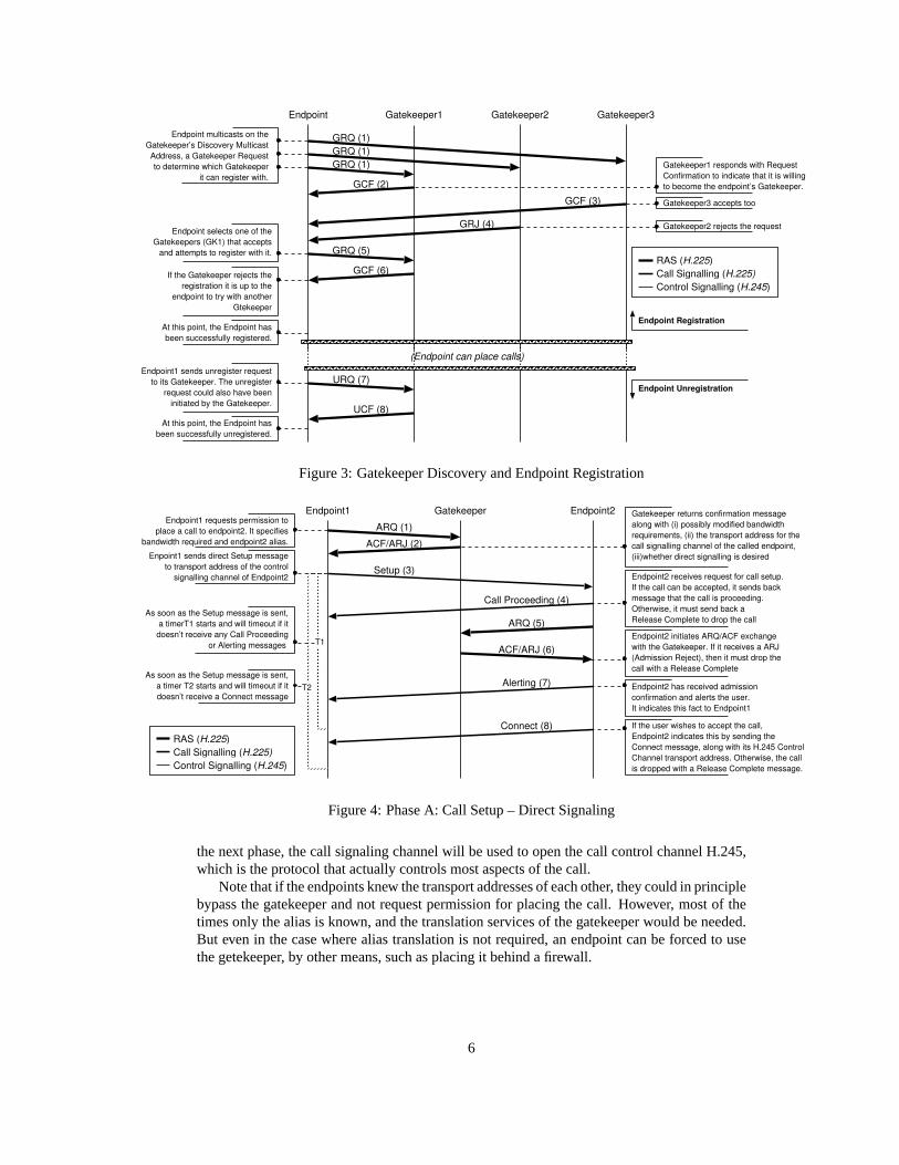
2.3.1 Gatekeeper Discovery and Endpoint Registration
Before placing any call with the help of a gatekeeper, each endpoint must make its presenceknown to the gatekeeper. This is accomplished through a short registration process. However,in order to register, the endpoint must find in some way the transport address of at least onegatekeeper. This phase is called Gatekeeper Discovery.
During gatekeeper discovery, an endpoint determines which gatekeeper it can register with.If this is not performed manually (i . e .the endpoint is configured with the transport address ofthe associated gatekeeper), H.323 provides an automatic method.
We demonstrate the auto discovery method with an example where one endpoint and threegatekeepers are involved. After the gatekeeper discovery phase completes, the endpoint pro-ceeds to register with one of the eligible candidates. We also show the symmetric deregistrationprocedure.
Once registered an endpoint can proceed to place calls with the help of the gatekeeper. Thedegree of involvement of the gatekeeper in the call varies between very small and completelyinvolved, depending on the portion of the call signaling that gets routed through it.
In our example, the gatekeeper will be minimally involved by translating endpoint aliasesto transport addresses and granting requests for the placement of a call (i . e .direct call andcontrol signaling will be used).
2.3.2 Phase A: Call Setup
The primary goal of this phase is to locate the called endpoint, establish whether the useraccepts the call and proceed with the setting up of the call signaling channel H.225. Then, in
5
Gatekeeper1 responds with RequestConfirmation to indicate that it is willingto become the endpoint’s Gatekeeper.
Endpoint Gatekeeper1
GRQ (1)
GRQ (1)GRQ (1)
GCF (2)
Endpoint multicasts on theGatekeeper’s Discovery MulticastAddress, a Gatekeeper Requestto determine which Gatekeeper
it can register with.
Gatekeeper2 Gatekeeper3
GCF (3)
GRJ (4)
GRQ (5)
GCF (6)
URQ (7)
UCF (8)At this point, the Endpoint has
been successfully unregistered.
Endpoint1 sends unregister requestto its Gatekeeper. The unregister
request could also have beeninitiated by the Gatekeeper.
RAS (H.225)Call Signalling (H.225)Control Signalling (H.245)
Gatekeeper3 accepts too
Gatekeeper2 rejects the requestEndpoint selects one of theGatekeepers (GK1) that accepts
and attempts to register with it.
If the Gatekeeper rejects theregistration it is up to the
endpoint to try with anotherGtekeeper
At this point, the Endpoint hasbeen successfully registered.
(Endpoint can place calls)
Endpoint Unregistration
Endpoint Registration
Figure 3: Gatekeeper Discovery and Endpoint Registration
Alerting (7)
Connect (8)
Endpoint1 Endpoint2Gatekeeper
Setup (3)
Call Proceeding (4)
ACF/ARJ (2)
ARQ (1)
ACF/ARJ (6)
ARQ (5)
RAS (H.225)Call Signalling (H.225)Control Signalling (H.245)
T2
T1
Endpoint2 has received admissionconfirmation and alerts the user.It indicates this fact to Endpoint1
As soon as the Setup message is sent,a timer T2 starts and will timeout if itdoesn’t receive a Connect message
Endpoint2 receives request for call setup.If the call can be accepted, it sends backmessage that the call is proceeding.Otherwise, it must send back aRelease Complete to drop the call
Endpoint2 initiates ARQ/ACF exchangewith the Gatekeeper. If it receives a ARJ(Admission Reject), then it must drop thecall with a Release Complete
If the user wishes to accept the call, Endpoint2 indicates this by sending theConnect message, along with its H.245 ControlChannel transport address. Otherwise, the callis dropped with a Release Complete message.
Endpoint1 requests permission toplace a call to endpoint2. It specifies
bandwidth required and endpoint2 alias.
Gatekeeper returns confirmation messagealong with (i) possibly modified bandwidthrequirements, (ii) the transport address for thecall signalling channel of the called endpoint,(iii)whether direct signalling is desired Enpoint1 sends direct Setup message
to transport address of the controlsignalling channel of Endpoint2
As soon as the Setup message is sent,a timerT1 starts and will timeout if it
doesn’t receive any Call Proceedingor Alerting messages
Figure 4: Phase A: Call Setup – Direct Signaling
the next phase, the call signaling channel will be used to open the call control channel H.245,which is the protocol that actually controls most aspects of the call.
Note that if the endpoints knew the transport addresses of each other, they could in principlebypass the gatekeeper and not request permission for placing the call. However, most of thetimes only the alias is known, and the translation services of the gatekeeper would be needed.But even in the case where alias translation is not required, an endpoint can be forced to usethe getekeeper, by other means, such as placing it behind a firewall.
6

2.3.3 Phase B: Initial Communication and Capability Exchange
Following the setup of the call signaling channel, the endpoints proceed to establish a H.245control channel. This is the most important channel, since messages exchanged through itcontrol all aspects of the call from this point of the call session.
After Endpoint1 has received the Connect message, it must have received (in the Connector a previous H.225 message) the transport address where Endpoint2 is listening for H.245control channel messages. Thus, Endpoint1 sets up the outgoing H.245 channel from its sideby sending the first message, TerminalCapabilitySet. This message advertises Endpoint1’sresource capabilities and contains its transport address for the channel, which in turn enablesEndpoint2 to open its outgoing side of the channel.
Note that the Control Channel H.245 could have been opened as soon as the transportaddress of the Endpoint2 H.245 channel was sent. This can happen in any of the Call Proceed-ing, Alerting and Connect messages. The H.245 channel may also have been established bythe Endpoint2 in the case that Endpoint1 had sent its H.245 transport address during setup.
The requirement is that one endpoint starts listening for H.245 messages on some transportaddress and advertises this address, through the H.225 call signaling channel (since only thisexists so far) to the other endpoint. The other endpoint does the same, but instead of sendingback its address through the H.225 channel, it sends it on the just created half-duplex (onlyone endpoint listens) H.245 channel. This first message is the TerminalCapabilitySet, whichcontains other information as well and enables the receiving endpoint to establish its side ofthe H.245 channel.
Endpoint1 Endpoint2Gatekeeper
TerminalCapabilitySet (1)
TerminalCapabilitySetAck(2)
TerminalCapabilitySet (3)
TerminalCapabilitySetAck(4)
MasterSlaveDetermination (6)
MasterSlaveDetermination(5)The two endpoints enter intoMaster/Slave determination
mode
By acknowledging receipt ofthe capabilities of Endpoint1,the H.245 channel has been
setup correctly and the rest ofthe call can be controlled
through this channel.
Enpoint1 sends its capabilitiesand the transport address where
it is prepared to receive H.245messages thus establishing the
H.245 channel.
RAS (H.225)Call Signalling (H.225)Control Signalling (H.245)
Master/Slave Determination
Capabilities Exchange
At this point any of the two endpointsmay close the Call Signalling connection(H.225) whose only purpose is to connectthe call and prepare the endpoints foropening the H.245 channel.
Endpoint2 sends its own capabilites.
Endpoint2 has received capabilites andtransport address for the H.245 controlchannel of Endpoint1. It acknowledges this.
Figure 5: Phase B: Initial Communication and Capability Exchange – Direct Signaling
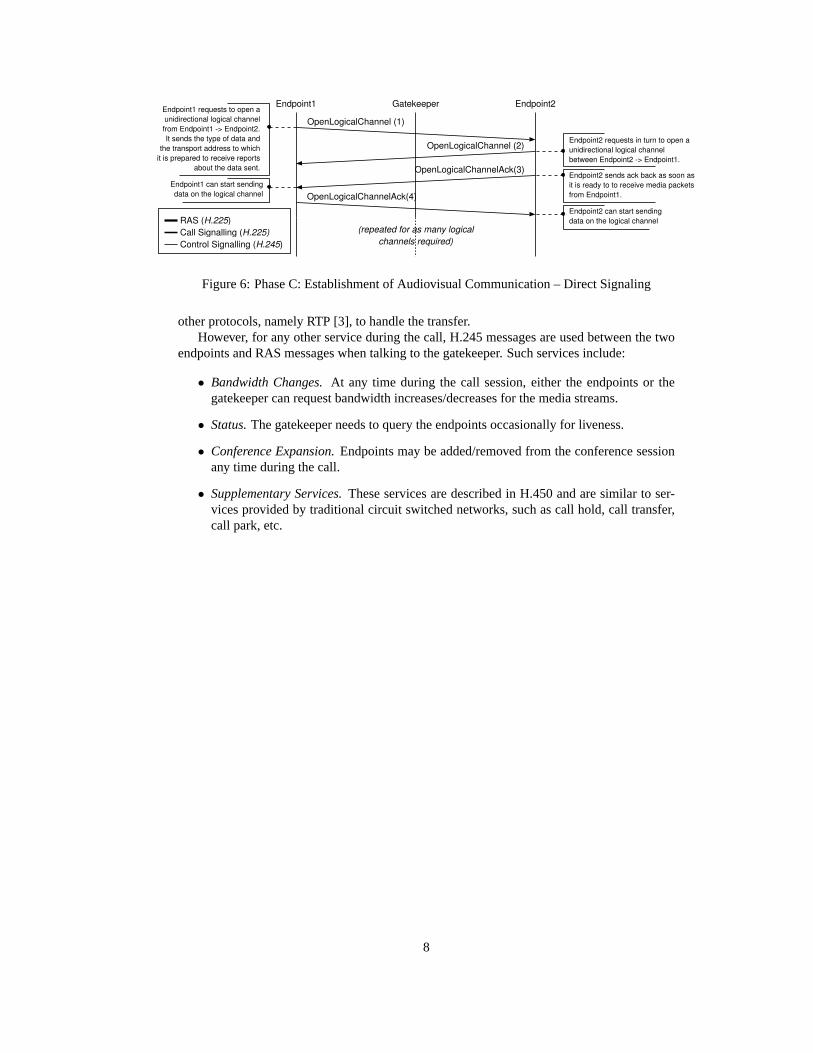
2.3.4 Phase C: Establishment of Audiovisual Communication
At this point, the control channel H.245 has been established, the endpoints know each other’scapabilities and they have determined master/slave relations. The endpoints proceed to openlogical channels for the exchange of media streams.
2.3.5 Phase D: Call Services
Everything is ready for the actual transfer of media packets, whether they are audio, video ordata. The protocol itself is not involved in the exchange of the actual media streams. It lets
7
Endpoint1 Endpoint2Gatekeeper
OpenLogicalChannel (1)
OpenLogicalChannelAck(3)
OpenLogicalChannel (2)
OpenLogicalChannelAck(4)
Endpoint1 requests to open aunidirectional logical channelfrom Endpoint1 -> Endpoint2.It sends the type of data and
the transport address to whichit is prepared to receive reports
about the data sent.
Endpoint1 can start sendingdata on the logical channel
(repeated for as many logicalchannels required)
RAS (H.225)Call Signalling (H.225)Control Signalling (H.245)
Endpoint2 requests in turn to open aunidirectional logical channelbetween Endpoint2 -> Endpoint1.
Endpoint2 sends ack back as soon asit is ready to to receive media packetsfrom Endpoint1.
Endpoint2 can start sendingdata on the logical channel
Figure 6: Phase C: Establishment of Audiovisual Communication – Direct Signaling
other protocols, namely RTP [3], to handle the transfer.However, for any other service during the call, H.245 messages are used between the two
endpoints and RAS messages when talking to the gatekeeper. Such services include:
• Bandwidth Changes.At any time during the call session, either the endpoints or thegatekeeper can request bandwidth increases/decreases for the media streams.
• Status.The gatekeeper needs to query the endpoints occasionally for liveness.
• Conference Expansion.Endpoints may be added/removed from the conference sessionany time during the call.
• Supplementary Services.These services are described in H.450 and are similar to ser-vices provided by traditional circuit switched networks, such as call hold, call transfer,call park, etc.
8

2.3.6 Phase E: Call Termination
Endpoint1 Endpoint2Gatekeeper
CloseLogicalChannel (1)
CloseLogicalChannelAck(3)
CloseLogicalChannel (2)
CloseLogicalChannelAck(4)Endpoint1 can stop listening
for reports on transport address
Endpoint1 seizes to transmit mediaand requests to close a previously
opened unidirectional logical channelbetween Endpoint1 -> Endpoint2.
RAS (H.225)Call Signalling (H.225)Control Signalling (H.245)
Endpoint2 stops listening on transport addressfor logical channel and stops sending receiverreport packets. Sends ack back to indicate this.
Terminating Signalling Channels
Closing of Logical Channels
Endpoint2 requests in turn to close apreviously opened unidirectional logicalchannel between Endpoint2 -> Endpoint1.
Endpoint2 can stop listeningfor reports on transport address
(repeated for as many logicalchannels required)
EndSessionCommand (5)
EndSessionCommand (6)
DCF (10)
ReleaseComplete (7)
DRQ (8)
DCF (11)
DRQ (9)
If the Call Signalling channel H.225 is stillopen then the Endpoint1 who initiated the
call termination sends the finalReleaseComplete message which
tears down the H.225 Channel
Endpoint1 tears down the H.245 channel
Endpoint2 sends the final message and tearsdown the H.245 channel. If the H.225 hasbeen already closed, then this is the lastmessage exchanged between the endpoints.
Endpoint1 sends a Disengage Request tothe Gatekeeper. This message (on the
RAS Channel) serves as a notification thatthe call resources are not longer needed.
The call has finished.
Endpoint1 initates tear down of H.245channel. Will keep listening to transportaddress of channel until peer endpoint
responds with the EndSessionCommand
Endpoint2 sends in turn a DisengageRequest to the Gatekeeper.
Figure 7: Phase E: Call Termination – Direct Signaling
At any point, either endpoint may terminate the call. The endpoints must close all thelogical channels they opened for media exchange, close the H.245 channel, close the H.225channel if still open and inform their respective gatekeepers about the end of the call.
9

Alerting (7)
Connect (8)
Endpoint1 Endpoint2Gatekeeper
Setup (3)
Call Proceeding (4)
ACF/ARJ (2)
ARQ (1)
ACF/ARJ (6)
ARQ (5)
TerminalCapabilitySet (9)
TerminalCapabilitySetAck(10)
TerminalCapabilitySet (11)
TerminalCapabilitySetAck(12)
MasterSlaveDetermination (14)
MasterSlaveDetermination(13)
OpenLogicalChannel (15)
OpenLogicalChannelAck(17)
OpenLogicalChannel (16)
OpenLogicalChannelAck(18)
CloseLogicalChannel (19)
CloseLogicalChannelAck(21)
CloseLogicalChannel (20)
CloseLogicalChannelAck(22)
EndSessionCommand (23)
EndSessionCommand (24)
DCF (28)
ReleaseComplete (25)
DRQ (26)
DCF (29)
DRQ (27)
Phase A: Call Setup
PhaseC: Establishment of Audiovisual communication
PhaseB: Initial Communication and Capability Exchange
PhaseE: Call Termination
RAS (H.225)Call Signalling (H.225)Control Signalling (H.245)
PhaseD: Call Services
(repeated for as many logicalchannels required)
(repeated for as many logicalchannels required)
(media exchange)
Figure 8: Complete Call (All Phases) – Direct Signaling
2.4 Advanced Functionality
In the previous section, we presented the essential functionality of the protocol in a straight-forward but also a somewhat simplistic manner. Without altering the spirit of the protocol, ad-vanced features were introduced at different stages of the protocol’s evolution. These featureshave made it more flexible to administrative control, especially when multiple administrativedomains are involved in a single call, and have succeeding in minimizing the rather large delayincurred during call setup.
10

2.4.1 Routing Signaling through Gatekeeper
So far, we have demonstrated the protocol with direct endpoint call signaling and direct con-trol channel (fig. 2), i . e .both the call signaling channel H.225 and the call control channelH.245 were established directly between the two endpoints, without any intervening entity.The gatekeeper was restricted into admitting and releasing calls.
H.323Gatekeeper
H.323Terminal
H.323Terminal
Control Channel H.245
Logical Channel (media)
RAS Cha
nnel
H.225 RAS Channel H.225
Logical Channel (media)
Call S
ignall
ing C
hann
el H.22
5 Call Signalling Channel H.225
Figure 9: Gatekeeper routed call signaling with direct endpoint control channel.
It is, however, possible to route either or both of the channels through the gatekeepersinvolved in the call. One of the possible alternatives is to route the call signaling channel H.225through the gatekeepers while still establishing a direct call control channel H.245 (fig. 9).In this case, the endpoints establish the call signaling channel H.225 with their respectivegatekeepers, which are responsible for forwarding any call signaling messages received bythem.
Another possible scenario is to route the call control channel H.245 as well through thegatekeepers (fig. 10). In this case, the two endpoints set up both the call signaling and the callcontrol channels with their respective gatekeepers and route all messages through them.
H.323Gatekeeper
H.323Terminal
H.323Terminal
Logical Channel (media)
RAS Cha
nnel
H.225 RAS Channel H.225
Logical Channel (media)
Call S
ignall
ing C
hann
el H.22
5 Call Signalling Channel H.225
Contro
l Cha
nnel
H.245 Control Channel H.245
Figure 10: Gatekeeper routed call signaling and control channel.
In the case where the two endpoints are in different zones, and as a result have differentcontrolling gatekeepers, more alternatives are possible. For example, one of the endpointsmay route all its messages through the gatekeeper of the zone it belongs to (thus using thegatekeeper routed model) while the other endpoint may exchange its messages directly withthe gatekeeper of the first endpoint (thus using the direct model because it bypasses its owngatekeeper).
The reasons for choosing among different routing schemes are multiple. In many cases,imposing constraints on the message routing scheme is necessary for billing and accounting
11

purposes. Or, the gatekeepers need to enforce tight bandwidth policing , or even for traversingfirewalls behind protected domains, etc. We should note here, that it is the gatekeeper whichspecifies the routing scheme, during the call admission phase, that an endpoint must abide toduring a call.
2.4.2 Optimization Techniques
The functionality of the protocol, as presented in section 2.3 involves a large overhead for asingle call, even in the case of a basic point-to-point voice call. The setup of the call session,before which no media content can be exchanged, takes almost 6 to 7 roundtrips. This delay ismost of the times unacceptable.
The call setup overhead incurs because, in order to open a logical channel for the transferof media content, even of the most basic form, the two endpoints must exchange OpenLogi-calChannel messages through an established H.245 call control channel. This channel, in turn,must be established by H.225 messages through the call signaling H.225 channel, which is thefirst channel that the two endpoints attempt to establish.
H.323Gatekeeper
H.323Terminal
H.323Terminal
Call Signalling Channel H.225
Logical Channel (media)
RAS Cha
nnel
H.225 RAS Channel H.225Setup
[OpenLogical Channel]
Connect[OpenLogical Channel]
Figure 11: Fast Connect procedure
The first optimization, the Fast Cconnect procedure, introduced in H.323v2, allows end-points to establish logical channels as soon as they exchange the first two messages that initiatethe call signaling channel. This can be achieved early in the call setup phase (section 2.3.2 dur-ing which the calling endpoint is allowed to include OpenLogicalChannel elements in the ini-tial Setup message. On receipt of the Setup message, the called endpoint can immediately startsending media content on the indicated channels and specifies which channels it accepts byincluding a special element in any message during this phase (i . e .until the Connect messageis sent).
In this fashion, the two endpoints have established media channels before even the com-pletion of phase A, i . e .before the receipt of the Connect message. This means that they canestablish a basic point-to-point call with as few as one roundtrip message exchange.
If the two endpoints need to open additional channels, or need to use enhanced call fea-tures, they need to open a H.245 control channel through the usual procedure (section 2.3.3).Otherwise, they can continue using the channels they opened during FastConnect throughoutthe call and close them when they tear down the call signaling channel at the end of the call.
Another optimization, introduced in H.323v3, is to encapsulate all H.245 control messagesin H.225 messages and send them through the call signaling channel, thus not requiring toestablish a separate H.245 call control channel. This is also known as H.245 tunneling (fig. 12).
In both cases, the H.323 call signaling channel must remain open for the duration of thecall. Note that FastConnect allows only the exchange of specific H.245 messages (only Open-LogicalChannel messages) and only during the first phase of call setup. In contrast, when
12

H.323Gatekeeper
H.323Terminal
H.323Terminal
Call Signalling Channel H.225
Logical Channel (media)
RAS Cha
nnel
H.225 RAS Channel H.225
Control Channel Tunnel H.245
Logical Channel (media)
Figure 12: H.245 tunneling.
H.323Gatekeeper
H.323Terminal
H.323Terminal
Call Signalling Channel H.225
RAS Cha
nnel
H.225 RAS Channel H.225
Control Channel Tunnel H.245
Logical Channel (media)
Setup[OpenLogical Channel]
Connect[OpenLogical Channel]
Figure 13: Fast Connect in parallel with H.245 tunneling.
using H.245 tunneling, the two endpoints behave as if they had indeed established a separateH.245 control channel, with the only difference that before sending a given H.245 message, ithas to be encapsulated into a H.225 message and sent through the call signaling channel.
Occasionally, it may be desirable to combine those two methods and initiate H.245 tunnel-ing in parallel with FastConnect (fig. 13). Since with FastConnect the two endpoints exchangeonly OpenLogicalChannel messages, there is no capability exchange and there are occasionsthat this may be required. Another reason is to have exchanged H.245 setup messages throughthe H.245 tunnel as fast as possible in case the FastConnect procedure fails.
2.4.3 Multiparty Conferencing
H.323 can be used to establish multipoint conferences.–Needs more work.
13

3 SIP Protocol Overview
SIP, which stands for Session Initiation Protocol, is an IETF application layer control protocol,defined in RFC 2543 [4], for the establishment, modification and termination of multimediasessions with one or more participants. SIP makes minimal assumptions about the underlyingtransport and network layer protocol, which can provide either a packet or byte stream servicewith either reliable or unreliable service.
3.1 System Description
Packet BasedNetwork
Domain B
LocationServer
SIP ServerProxy/Redirect
PSTNNetwork
SIPGateway
SIP User Agent(visiting from A)
SIP User Agent(at homel)
Domain A
SIPRegistrar
LocationServer
SIP ServerProxy/Redirect
H.323Network
SIPGateway
SIP User Agent(at home)
SIP User Agent(at home)
SIPRegistrar
Figure 14:
A SIP system is based on a client/server model and is comprised of the following logicalentities:
• A User Agent (UA)is an application that acts on behalf of the user, both as a client (UserAgent Client) and as a server (User Agent Server). As a client it initiates SIP requestsand as a server it accepts calls and responds to SIP requests made by other entities. Theuser agent is usually part of a multimedia terminal whose media capabilities it controlswithout having any media capabilities of its own.
• A Registrar Serveris a SIP server that accepts only registration requests issued by useragents. A registrar server never forwards requests.
• A Location Serveris a server which provides information to a proxy/redirect serverabout the possible current locations of a user. Usually, this entity is part of the proxy/redirectservers.
• A Redirect Serveris a SIP server that provides address mapping services. It respondsto a SIP request destined to an address with a list of new addresses. A redirect serverdoesn’t accept calls, doesn’t forward requests nor does it initiate any of its own.
14

• A Proxy Serveris a SIP server that acts both as a server to user agents by forwardingSIP requests and as a client to other SIP servers by submitting the forwarded requests tothem on behalf of user agents or proxy servers.
With the exception of the user agent, which is usually part of a multimedia terminal, therest of the logical entities (registrar, redirect and proxy servers)a may be combined in a singleapplication. Therefore, a single entity can act either as a proxy or as a redirect server, accordingto the SIP request, and at the same time accept registration requests. A SIP call is defined asthe multimedia conference consisting of all participants invited by a common source.
Although not partitioned formally, the SIP system can be viewed as divided into domainseach serviced by one redirect/proxy server and one registrar. A user agent has usually a homedomain, which is specified by its address, but it can roam and use services in other domains aswell, in which case it is considered to be ’visiting’. Otherwise it is considered to be ”at home”.
3.2 Signaling Approach
The SIP protocol follows a web based approach to call signaling, contrary to traditional telecom-munication protocols. It resembles a client/server model, where SIP clients issue requests andSIP servers return one or more responses. The whole signaling protocol is built on this ex-change of requests and responses, which are grouped into ”transactions”. Many of the SIPentities are comprised of both a client and a server side and the protocol has been designed insuch a way that the entities can be either stateful or stateless.
SIP doesn’t establish separate signaling channels for setting up and controlling the call.Instead, it defines the notion of transactions which consist of one request, sent by a client to aserver, followed by zero or more provisional responses and one final response from the server.All the messages of a transaction share a common unique identifier and traverse the same setof hosts.
There are two types of messages in SIP; requests and responses. Both of them use thetextual representation of the ISO 10646 character set with UTF-8 encoding. The messagesyntax follows HTTP/1.1, but it should be noted that SIP is not an extension to HTTP.
SIP defines a handful of request messages and a hierarchy of SIP responses. Each requestand response method is comprised of header fields, which are either required, optional or notapplicable, and a message body, which may be optional. Most of the times, the header fieldsare the ones that hold most of the information exchanged in the protocol. A subset of theheader fields can be abbreviated by single letters, thus condensing the size of the messages.This form of compression is referred to as ”tokenization”.
When setting up a session, SIP messages need to describe the session characteristics to thepeer user agent. SIP recommends but does not mandate the use of the the Session DescriptionProtocol SDP, defined in RFC 2327 [5]. The session description is used for communicatingthe parameters required to establish the media channels for the transfer of the media contentof the call session.
3.3 Basic Functionality
SIP is used for setting up, managing and tearing down multimedia conferences. It shouldbe stressed that the actual delivery of the media content lies outside the scope of the SIPspecification. SIP addresses the following aspects of multimedia communications:
1. User Location.The system provides means to determine the transport address where theuser agent server of the called SIP endpoint listens for SIP requests.
15
2. User Capabilities.The system is responsible for determining the multimedia capabilitiesof each endpoint participating in the call and should ensure that they can communicatewith each other if their capabilities are compatible.
3. User Availability.The system must determine if the called user is willing to engage intocommunication with the requesting endpoint.
4. Call Setup.The system should alert the user and configure both endpoints in such a waythat the call can proceed.
5. Call Handling. The system, while not responsible for the transfer of the media con-tent, should provide the means to modify the characteristics of the call session, such asadding/deleting media channels or call participants.
6. Call Termination. Finally, the system must terminate the call session upon the user’srequest and ensure that even when some endpoint doesn’t follow the proper terminationprocedure, the call resources are released and the call session terminated.
A typical call session consists of a number of transactions between the user agents and theintervening protocol entities. The requests are issued from a user agent client, a proxy serveracting on behalf of a user agent client or another proxy server. Each request prompts one ormore responses from a user agent server or a proxy/redirect server that received the request.All the messages from the request until the final response constitute a transaction and can beexchanged directly by two entities or traverse one or more proxy servers along the way.
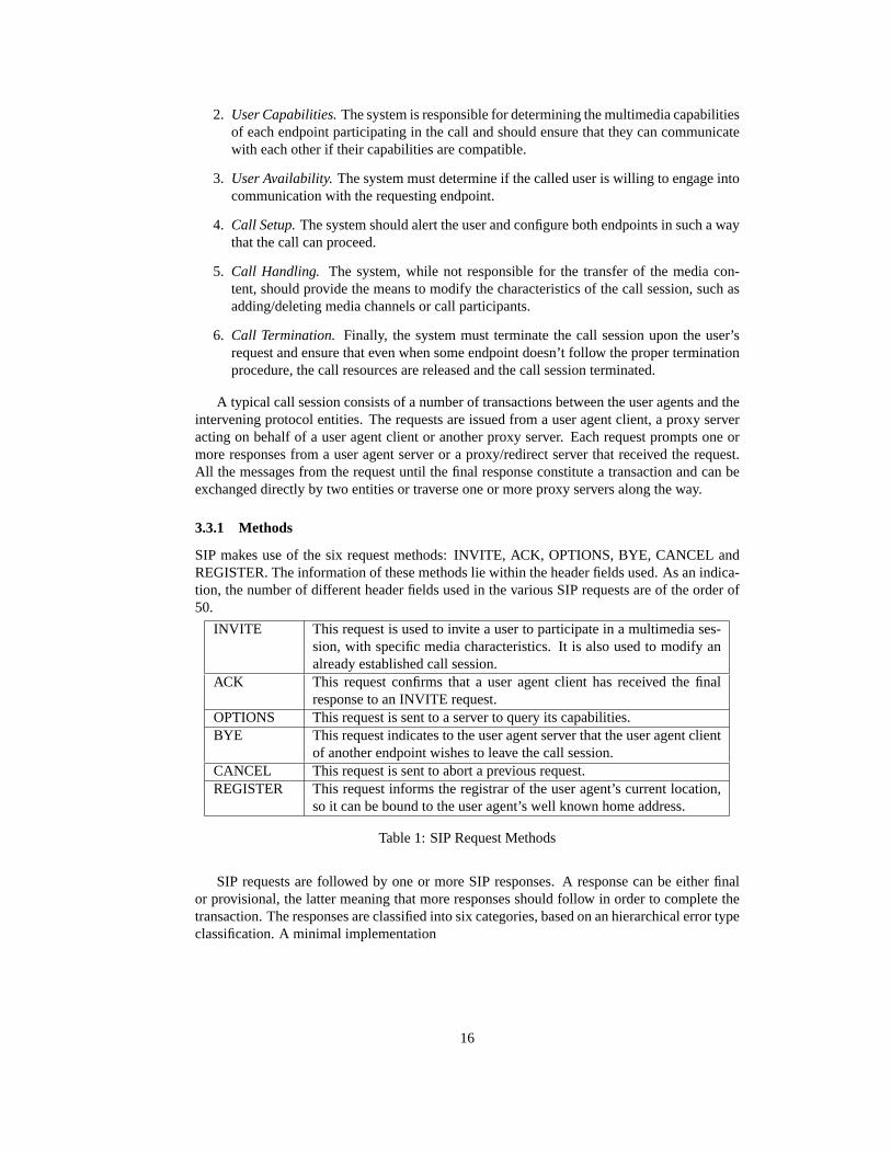
3.3.1 Methods
SIP makes use of the six request methods: INVITE, ACK, OPTIONS, BYE, CANCEL andREGISTER. The information of these methods lie within the header fields used. As an indica-tion, the number of different header fields used in the various SIP requests are of the order of50.
INVITE This request is used to invite a user to participate in a multimedia ses-sion, with specific media characteristics. It is also used to modify analready established call session.
ACK This request confirms that a user agent client has received the finalresponse to an INVITE request.
OPTIONS This request is sent to a server to query its capabilities.BYE This request indicates to the user agent server that the user agent client
of another endpoint wishes to leave the call session.CANCEL This request is sent to abort a previous request.REGISTER This request informs the registrar of the user agent’s current location,
so it can be bound to the user agent’s well known home address.
Table 1: SIP Request Methods
SIP requests are followed by one or more SIP responses. A response can be either finalor provisional, the latter meaning that more responses should follow in order to complete thetransaction. The responses are classified into six categories, based on an hierarchical error typeclassification. A minimal implementation
16

1xx Informational(provisional)
Request received, continuing to process request. The client shouldwait for further responses from the server.
2xx Success(final)
The action was successfully received, understood and accepted.The client must terminate any search.
3xx Redirection(final)
Further action must be taken in order to complete the request. Theclient must terminate any existing search but may initiate a newone.
4xx Client Error(final)
The request contains bad syntax or cannot be fulfilled at thisserver. The client should try another server or alter the requestand retry with the same server.
5xx Server Error(final)
The request cannot be fulfilled at this server because of server er-ror. The client should try with another server.
6xx Global Failure(final)
The request is invalid at any server. The client must abandonsearch.
Table 2: SIP Request Methods
3.3.2 Registrar Discovery and User Agent Registration
UA1("at home" in Domain A)
UA2(in Domain B
"visiting" from Domain A)
SIP RegistrarDomain A
REGISTER
SIP RequestSIP Final ResponseSIP Provisional Response
SIP RegistrarDomain B
REGISTER
REGISTER UA2 also registers with its home domainRegistrar so that any INVITE request for UA2,which would normally reach the proxy serverin domain A, will be redirected or forwardedto the proxy server of domain B.
UA2 is visiting from domain A.It registers with the local SIP registrar inthe domain that it is (domain B) so thatINVITE requests destined for UA2 willreach it if they reach the local Proxy server.
UA1 belongs to domain A, i.e. in itsSIP address, the domain of the UA is
domain A. The implication of this is thatfrom any point of the network, if another
UA wishes to invite UA1 to a session,then its request would normally reach
the proxy server of domain A.
That is why it should register its locationwith the Registrar of its own domain.
This is sufficient, since its location lieswithin its own administrative domain.
Figure 15:
Before receiving any calls through a proxy server, a user agent must register the addresswhere it can be reached. This may be one or more addresses which are not restricted only to SIPaddresses (for example it can point to a web page, email address, voicemail, etc). Furthermore,any call handling preferences may be specified during registration. Registration is required forthe user agent to receive calls at its current location; not necessarily for placing calls. However,if the user agent needs to use the local proxy server for placing a call, the server may refuse tohonor the request depending on its policy.
A user agent should always register its current location with its home registrar, regardless ofthe domain it is currently in. If the user agent is visiting another domain, it must, in addition toits home registrar, also register with the local registrar; otherwise it will not be able to receiveany calls. Usually, a user agent should attempt to register periodically because registrationrequests expire after a specified amount of time.
A user agent needs to locate either the registrar or the proxy server of the domain in whichit attempts to register. Most of the times the proxy server and the registrar are combined in thesame application; otherwise, the proxy server knows how to forward the registration request tothe registrar. So, it suffices for a user agent to locate the proxy server of the domain it wishes
17

to register. Two cases are distinguished, depending on which server the user agent attempts toregister with:
1. Local Server:The user agent should attempt to register with the default outbound proxyserver, if one is configured. If no server has been configured, then the user agent shouldattempt to send a registration request to the well known multicast address of all SIPservers ”sip.mcast.net” but scoped appropriately so it doesn’t leave the local administra-tive domain.
2. Home Server:If the user agent is visiting a different domain, then this server is differentfrom the local server. The user agent should attempt to register with its home server,deriving its address from its home address.
3.3.3 Call Session Establishment and Teardown
UA1 UA2SIP Proxy1 SIP Proxy2
INVITE (1)INVITE (2)
INVITE (3)
180 Ringing (4)180 Ringing (5)
180 Ringing (6)OK (7)
OK (8)OK (9)
ACK (10)
UA1 can indicate to the user that the agentat the other end is "ringing" the called user.
UA1 invites UA2 to participate in a session.UA1 sends its reques to its default outgoing
proxy server Proxy1 which forwars the request to the proxy server in the domain ofUA2, Proxy2. The request contains, except
for the address of the called UA, all the mediatypes that UA1 is willing to receive/send. At thispoint, UA1 must be prepared to receive mediacontent on every advertised transport address.
T1
T1
Call Termination
SIP Call Setup
SIP RequestSIP Final ResponseSIP Provisional Response
BYE (11)
OK (10)T1
Call Handling(media exchange)
UA2 wishes to disengage from the conversationand sends a BYE request to terminate the call.UA2 must stop sending media content to UA1but should still listen for media content from UA1.
UA2 can stop listening for media content fromUA1. The call session has been terminated.
User is willing to accept the call, so the UA2 sendsa final OK response accepting or rejecting specificmedia types offered by UA1 and also lists mediatypes it is willing to receive. UA2 must be ready toreceive media content immediately.To conclude the call setup, UA1 must
acknowledge receipt of OK response, whichconstitutes a transaction of its own.
Note that the ACK can traverse a differentset of hosts than the INVITE requestand can be sent directly to the UA2
Proxy knows the location of UA2 and forwardsthe INVITE request. All subsequent responsesof the transaction will follow the same path.
UA1 has received a BYE request from UA2.That means that UA2 has seized transmiting
media content and UA1 stops transmiting mediacontent itselt. It sends back acknowledgment.
The call session has been terminated.
UA2 receives INVITE request and alerts user.Indicates this fact by sending back the provisionalresponse Ringing. Also, this indicates that mediacapabilites are compatible.
UA1 receives final OK response. Thisconcludes the INVITE transaction.
Figure 16:
In order to place a call, a user agent issues an INVITE request destined for the called useragent. This request is sent either through a default outbound proxy server, regardless of thedestination address, or directly to the proxy server of the called user agent’s home domain.
Each proxy may modify the INVITE request and then forward it or issue new concurrentor sequential multiple INVITE requests to locate a user agent at multiple locations. The IN-VITE request traverses one or more proxy servers before it reaches the destination user agent.Once this happens, the called user agent sends back (through the same route) zero or moreprovisional responses while it attempts to alert the user. Finally, it sends back a final responseindicating the willingness of the user to accept the incoming call. This concludes the first SIPtransaction of the session and has accomplished to locate the called user agent, alert the userand exchange media capabilities through session descriptors. The call is set up once the calleruser agent acknowledges the acceptance of the call.
18

The two endpoints can engage now into conversation. If the call characteristics need to bemodified at mid-session, then further INVITE transactions are needed to convey the new ses-sion description. When the conversation is over, either user agent initiates a BYE transactionwhich terminates the call session.
3.4 Advanced Functionality
3.4.1 Mutliple Redirect and Proxy Servers
UA1 UA2SIP Redirect
Server2
INVITE (1)INVITE (2)
180 Ringing (13)
SIP ProxyServer1
SIP ProxyServer3
SIP ProxyServer4
302 Moved (3)
ACK (5)100 Trying (4)
404 Not Found (9) INVITE (8)
180 Ringing (12)180 Ringing (11)
180 OK (16)
180 OK (15)180 OK(14)
INVITE (7)
INVITE (6)
ACK (10)
ACK (17)
UA1 sends an INVITE request to itsdefault outgoing proxy server Proxy1
Redirect2 returns a list of addresseswhere UA2 might be contacted.
Proxy1 forwards INVITE to redirect server
Proxy1 calculates that it will take longerto contact UA2 and informs UA1
Proxy1 sends two INVITE messages inparallel to Proxy3 and Proxy4 as a result
of the list of addresses it received.
Proxy3 couldn’t locate UA2
Proxy4 located UA2 and forwarded theINVITE message, which prompted the
provisional response 180 Ringing,which is propagated back to the UA2
UA2 accepts the call and sends OK,which ends the transaction initated by
the INVITE request of UA1, which inturn sends an ACK request to confirm
the call setup.
SIP RequestSIP Final ResponseSIP Provisional Response
Figure 17:
So far we have seen the simple case where the intermediate servers always behave asproxy servers and forward the request. Another alternative is for the intermediate server to bea redirect server, in which case the INVITE request is not forwarded, but instead it is respondedto with a list of alternative addresses for the initiating end to try. Whatever the case may be,the request reaches its destination user agent, if the latter has registered properly at its localand home server.
In figure 17 we present the case of two user agents attempting to set up a call sessionbetween them. UA1 sends the INVITE request to its default outbound proxy1. In turn, proxy1forwards the request to redirect2 which instead of further forwarding the request, it returns alist of addresses where UA2 may be contacted. For example, this could be the home serverfor UA2 which is now visiting other domains. Proxy1, on receipt of the list of alternativeaddresses, launches a concurrent search for UA2 by sending INVITE requests to both proxyservers of the destination domains (proxy3, proxy4). Proxy3 denies the request because itcannot locate UA2 but proxy4 locates the called user agent and forwards the INVITE request.In the usual way, UA2 returns one provisional and the final response to UA1 through the sameroute, but UA1 chooses to acknowledge the call setup directly to UA2.
3.4.2 Multiparty Conferencing
SIP can be used to establish multipoint conferences, but for the time being it doesn’t provideany floor control.–Needs more work.
19

4 Related Work
Since both H.323 and SIP have emerged as competing protocol standards, aiming at providingsignaling and call control for IP telephony, it is expected that considerable attention should bedrawn to broad and thorough comparative analysis of the two protocols.
In this section, we will review previous work comparing the two protocols by outliningtheir major points and examining their strengths and weaknesses. Then in the next section wewill describe how we can supplement this work, by providing a more quantitave comparisonof the two protocols using a combination of analysis, measurements and simulation of theprotocol operations.
We will examine three major comparisons that can be found in the literature. The firstwas compiled by Nortel Networks in 2000 and compares the two protocols as candidates forinclusion in UMTS2000. The second is by Dalgic and Fang in 1999 which focus on featuresand characteristics most relevant to IP telephony and the third is by Schulzrinne and Rosenbergin 1998, two of the main contributors to the evolution of SIP.
With the exception of the first comparative work [9], most analyses restrict themselves togeneral conclusions on the various aspects of the two protocols, such as complexity, extensibil-ity, scalability and services. Their conclusions are based largely on comparing, in a qualitativemanner, the two protocols, such as contrasting the required number of round trips for eachoperation, speculating on the processing time of the fields in each protocols’ headers, and stat-ing observations that seem to be based more on the overall protocol behaviour rather than onmeasurements of the specific, real or simulated, protocol operation.
4.1 A Comparison of H.323v4 and SIP
By Nortel Networks, 2000 [9].
This technical report by Nortel Networks, is quite comprehensive and it aims at facilitatingoperators and vendors in selecting a control protocol for UMTS 2000. It compares SIP andH.323 version 4, based on complexity, extensibility, scalability, resource utilization, resourcemanagement, services and also considers how well each can perform in a wireless environ-ment. Their main goal is to establish whether either call control protocol provides a significantadvantage over the other in terms of the various categories mentioned above.
The report starts directly by comparing the two protocols on factors that, according to theauthors, are important when choosing a protocol. The major criteria they use for their analysisare (i) time to market, (ii) estimated quantification of the work effort required and (iii) identifi-cation and quantification of the impact on the various network elements. They do not considerprevious versions of H.323, and they assume that UDP is used in both protocols. Their resultsare quite comprehensive; they provide call flows of each protocol for many services, focusingon the case where a SIP or H.323 entity communicates with a UMTS 2000 entity and also, insome cases, they provide a few numerical results.
4.1.1 Complexity
• Message Set.The two protocols are similar but currently H.323 over UDP is not reliableand the mechanisms of Annex E must be used to provide reliability.
• Encoding and Generation.SIP compression/generation overhead is less (almost by afactor of two) than H.323 ASN.1 PER encoding/generation.
20

Criteria H.323v1 SIP Choice/ReasonMessage Set Complex, many mes-
sages for similar func-tionality
Logically numbered re-sponses for extension,smaller set of messagesfor same functionality.
SIP - Time-to-marketand extensibility
Debugging Have to alter tools oneach extension
Simple Tool developedonce
SIP - Time-to-marketand reduced complex-ity of development.
Re-use of code H.323 and H.32x SIP and Web SIP - more modularService and Proto-col
H.323 and H.32x SIP and Web - moremodular
SIP - more modular
Methods forimplementingservices
Can support all Can support all Equivalent
Distributed CallSignaling
Can Support Can Support SIP - Time-to-market /reduced complexity
Table 3: Complexity: Summary of results.
• Decoding and Parsing.The two protocols have the same overhead. If tokenized com-pression is used in SIP, then the overhead becomes less than that of H.323.
• Debugging. The authors favor SIP which in contrast to H.323 which requires specialdebugging tools, is simple to debug and has reduced complexity for development.
• Implementing Services.H.323 is less flexible than SIP, since H.323 has to add specificfields or parameter values in the signaling. In contrast, SIP combined with SDP for thesession description provides this functionality transparently, due to its modular design.
• Interworking with the PSTN.The authors point out that the choice of signaling proto-col is irrelevant to this issue, since most of the issues being debated concern inbandstreaming and QoS interactions.
• Required Memory.The stack size of SIP is smaller than the H.323 stack, thus loweringthe memory requirements when using SIP.
4.1.2 Extensibility
• Compatibility among versions.SIP doesn’t state explicit requirements for compatibilityamong versions, thus reducing code size and complexity. However it may have theadverse effect of newer versions not supporting features of older versions. H.323 on theother hand requires full backward compatibility, a fact that has resulted in very largecode for H.323 implementations. The authors recommend that new implementationsshould not retain backwards compatibility for versions prior to H.323v4.
• Feature evolution.According to the authors SIP is much more flexible in defining newfeatures and services, since it has built-in extensibility mechanisms, it is text based andis quite modular. On the other hand, H.323 is quite complex in defining new featuresand furthermore requires new vendor codes to be specified, a process that is quite timeconsuming.
• Modularity. SIP provides mainly user location, registration and basic session signaling.For further services and features other protocols can be used with SIP without making
21

Criteria H.323v1 SIP Choice/ReasonVersion Compati-bility
YES YES - the Requires,Supported and Prox-yRequire headers pro-vide more flexibilitythan H.323.
SIP - more flexibilityto support for multiplevariants coexisiting.
Feature Evolution Same as above Same as above Same as aboveOperators incharge of ownservices
Less Ability - morecomplex ASN.1
Higher Ability - textformats and extensionheaders
SIP - Operators will beless dependent in ven-dors to add new ser-vices.
Modularity Umbrella Standard -designed for limitedfeature set.
Modular, designedaround other webtechnologies and cando GSTN services too.
SIP - built for web.H.323 originally de-rived from circuitworld.
Codecs Equivalent Equivalent EquivalentThird party CallControl
Facility redirect Also header Equivalent
Table 4: Extensibility: Summary of results.
any changes to the basic protocol, thus providing large degree of modularity and flexibil-ity, since even new headers can be added and pass through intermediate proxies and useragents. On the other hand, in H.323 there is no clean separation between its numeroussubprotocols, which are closely intertwined to provide most of the built-in services.
• Ability to work with existing an new multimedia codecs.SIP requires the codec to beregistered with IANA before it can be used. Any person or group may register such acodec with IANA. H.323 makes no such requirement and a new codec can be used withno modifications of the H.245 syntax.
• Third-Party Call Control Mechanisms.This can be supported easily and concisely inSIP. While it is also possible to support it in H.323, there is no standard comprehensiveway to do it.
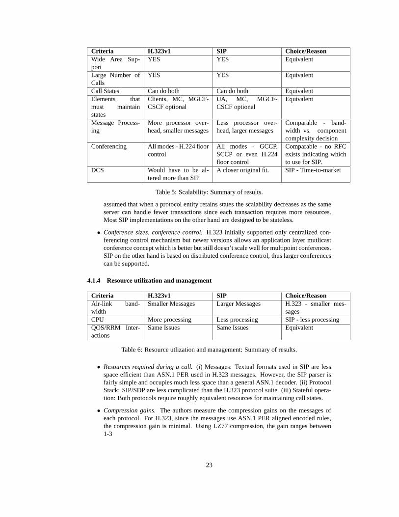
4.1.3 Scalability
• Support of large number of domains.Both protocols seem to be equivalent. In both SIPand H.323 the burden falls on the main network server (proxy server for SIP, gatekeeperfor H.323), the underlying transport layer and the way peer entities communicate. Theyboth accommodate different topologies (flat, hierarchical) and both can make use ofvarious location and translation mechanisms suitable for global deployment.
• Ability to handle large number of calls.The authors note that this is primarily implemen-tation/deployment specific. Both protocols can function in a stateless manner. However,most H.323 implementations are likely to be stateful. They also note that SIP takes lessCPU cycles to generate signaling messages, thus they hypothesize that a server couldhandle more transactions.
• Maintaining of call states effect on scalability.Both protocols support stateless andstateful operation, but most H.323 carrier grade implementations are designed to bestateful and use hot-sparring techniques, which increases the complexity. It is generally
22
Criteria H.323v1 SIP Choice/ReasonWide Area Sup-port
YES YES Equivalent
Large Number ofCalls
YES YES Equivalent
Call States Can do both Can do both EquivalentElements thatmust maintainstates
Clients, MC, MGCF-CSCF optional
UA, MC, MGCF-CSCF optional
Equivalent
Message Process-ing
More processor over-head, smaller messages
Less processor over-head, larger messages
Comparable - band-width vs. componentcomplexity decision
Conferencing All modes - H.224 floorcontrol
All modes - GCCP,SCCP or even H.224floor control
Comparable - no RFCexists indicating whichto use for SIP.
DCS Would have to be al-tered more than SIP
A closer original fit. SIP - Time-to-market
Table 5: Scalability: Summary of results.
assumed that when a protocol entity retains states the scalability decreases as the sameserver can handle fewer transactions since each transaction requires more resources.Most SIP implementations on the other hand are designed to be stateless.
• Conference sizes, conference control.H.323 initially supported only centralized con-ferencing control mechanism but newer versions allows an application layer mutlicastconference concept which is better but still doesn’t scale well for multipoint conferences.SIP on the other hand is based on distributed conference control, thus larger conferencescan be supported.
4.1.4 Resource utilization and management
Criteria H.323v1 SIP Choice/ReasonAir-link band-width
Smaller Messages Larger Messages H.323 - smaller mes-sages
CPU More processing Less processing SIP - less processingQOS/RRM Inter-actions
Same Issues Same Issues Equivalent
Table 6: Resource utlization and management: Summary of results.
• Resources required during a call.(i) Messages: Textual formats used in SIP are lessspace efficient than ASN.1 PER used in H.323 messages. However, the SIP parser isfairly simple and occupies much less space than a general ASN.1 decoder. (ii) ProtocolStack: SIP/SDP are less complicated than the H.323 protocol suite. (iii) Stateful opera-tion: Both protocols require roughly equivalent resources for maintaining call states.
• Compression gains.The authors measure the compression gains on the messages ofeach protocol. For H.323, since the messages use ASN.1 PER aligned encoded rules,the compression gain is minimal. Using LZ77 compression, the gain ranges between1-3
23

In the case of SIP, the authors first used tokenization of the header fields (replacinglong header field strings with one character tokens). They observed a gain ranging be-tween 13-19Then, they applied a common text compression technique and the additionalgains ranged between 18-22SIP the usage of tokenization, since it does not incur addi-tional CPU overhead. However, they recommend against compressing further, sincethey expect the compression/decompression overhead to impose additional burden onthe system.
4.1.5 Services
Criteria H.323v1 SIP Choice/ReasonSupported Ser-vices
H.323 more explicitlydefined
SIP defined in whitepa-pers and drafts
Equivalent but H.323has better standardiza-tion
Delay Times Equivalent - still issueswith use of UDP andreliability
Equivalent Equivalent
Billing Needs work - to be em-bedded in protocol
Needs work - to use aseparate protocol
Comparable
GSTN services YES YES SIP - Time-to-market /less code
CapabilitiesExchange
Better for media -worse for signalingextensibility
Worse for media - bet-ter for signaling exten-sibility
SIP - signaling is moreof an issue
Personal Mobility Added nomadicity inv3 - location based ser-vices still ongoing
Designed for nomadic-ity - location based ser-vices still ongoing
Comparable
Legacy interoper-ability
H.246 Draft status H.323
IP telephony inter-operability
Monolithic / OS bun-dled client
DCSGROUP / MGCP /SDP
SIP
Security H.235 added later.Worse for firewalltraversal using UDP.
Designed for it origi-nally. Better for fire-wall traversal,
Comparable
Table 7: Services: Summary of results.
• Services supported.Both protocols provide almost the same services. In H.323, theservices supported are standardized in the H.450 series of specifications, while in SIPservices are not defined rigorously in the main RFC but are left to white papers and otherinformational RFCs.
• Delay times to acquire services.Using UDP, call setup delay is equivalent in SIP andH.323 if the FastConnect procedure is used in the latter. H.323 differs by setting up inparallel a backup TCP connection while SIP sets up the TCP connection sequentially,after the failure of UDP.
24

4.1.6 Conclusions
The authors then proceed with a list of comparison questions and answers aimed primarily atclarifying and supplementing the analysis in the first part. Many details are provided as wellas quite a few message flows for many of the services. They mainly focus on issues regardinghow each protocol interacts with the UMTS 2000 architecture.
Finally, the authors conclude by recommending SIP as their preference for a control proto-col. They point out that even though H.323, unlike SIP, has currently more enterprise orientedand campus scale products deployed, SIP provides long term benefits which are related to andaffect time to market, extensibility, multi-party service flexibility, ease of interoperability andcomplexity of development.
4.2 Comparison of H.323 and SIP for IP Telephony Signaling
By Dalgic and Fang, 1999 [10].
This paper by Dalgic and Fang is much less comprehensive than [9] but more detailedthan [11]. It compares SIP and H.323 versions 1, 2 and 3, based on functionality, QoS, scal-ability, flexibility, interoperability and ease of implementation. However, it doesn’t containany quantitative results. Most conclusions rely on studying the behaviour of the protocols asdescribed in their specifications; not as they behave in a real or simulated environment.
The paper gives a brief overview of the 2 protocols and then proceeds to compare theprotocols on various categories. In most cases they present the detailed signaling exchangedfor the two protocols for a specific service and then they juxtapose the two behaviours to drawtheir conclusions. Much work has been put into describing the call control services that eachprotocol provides. We summarize the main points of the analysis.
4.2.1 Functionality
• Services.Both protocols provide a rich set of services but each provides it with a differ-ent approach.
• Call Control Services.Most call control services (such as call hold, call transfer, callforwarding, call waiting etc.) are supported by both protocols.
• Third Party Control.Only available in SIP.
• Capability Exchange.The H.323 mechanism for capability exchange is much moreprecise and flexible than the corresponding mechanism in SIP.
4.2.2 QoS
• Admission Control.Provided by H.323v3 but not by SIP
• Resource Reservation.Not supported by any protocol, and both of them recommendusing an external method such as DiffServ or IntServ.
• Call Setup Delay.Very large in H.323v1, shorter in H.323v2 with fast start and compa-rable with SIP in H.323v3. H.323v3 can use both UDP and TCP, making it as fast asSIP.
25

• Error Detection and Correction.Not an issue in H.323 v1 and v2 since TCP, a reli-able transport protocol, is used. In H.323v3, where UDP can be used, a retransmissionscheme is implemented to ensure reliability. In SIP a similar retransmission scheme isused.
• Loop Detection. SIP implements a loop detection algorithm similar to the one usedin BGP (Border Gateway Protocol), which is much more efficient than the simplisticalgorithm used in H.323v3. H.323 v1 and v2 didn’t have any provision for detectingloop paths.
• Fault Tolerance.H.323 v3 provides better fault tolerance than SIP by redundant gate-keepers and endpoints.
4.2.3 Scalability
• Complexity. SIP is simpler to program and maintain than H.323 and therefore morescalable.
• Server Processing.H.323 v1 and v2 rely on TCP for reliability and in consequence mustbe stateful. H.323v3 on the other hand can be stateless, just as SIP, which lowers theserver processing demands.
• Endpoint Location.H.323 uses alias mapped by the gatekeepers, while SIP makes useof a SIP URL.
4.2.4 Flexibility
• Extensibility of Functionality.SIP offers a more flexible extension mechanism throughthe use of a hierarchical namespace of feature names, while in H.323 extensibility isachieved through a vendor defined extension field.
• Ease of Customization.H.323 requires more interactions between its sub-protocols, andits size always increases since backward compatibility is required. On the other hand,SIP uses its header fields encoded in text, making customization much easier in this case.
4.2.5 Interoperability
• Among Versions.H.323 is fully backward compatible with all versions. In SIP newerversions tend to phase out older functionality if it is not used.
• Among Implementations.H.323 provides a ”Implementers Guide” which clarifies thestandard and smoothes interoperability problems among different implementations. SIPdoesn’t provide yet a similar implementation agreement.
• With Other Signaling protocols.The H.32x family of protocols fully specifies standardsto interoperate with other protocols, namely circuit switched networks.
4.2.6 Ease of Implementation
• Development time.H.323 requires a special parser for ASN.1 syntax which complicatesimplementation and debugging. SIP text based message encoding allows easy imple-mentation and debugging.
26
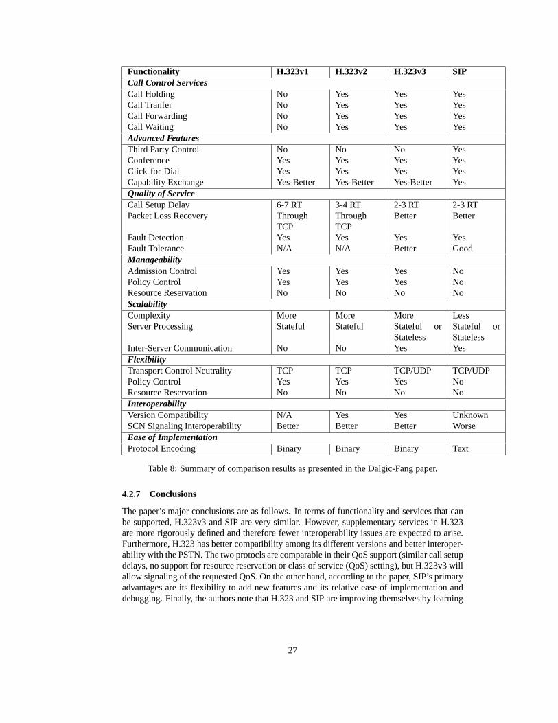
Functionality H.323v1 H.323v2 H.323v3 SIPCall Control ServicesCall Holding No Yes Yes YesCall Tranfer No Yes Yes YesCall Forwarding No Yes Yes YesCall Waiting No Yes Yes YesAdvanced FeaturesThird Party Control No No No YesConference Yes Yes Yes YesClick-for-Dial Yes Yes Yes YesCapability Exchange Yes-Better Yes-Better Yes-Better YesQuality of ServiceCall Setup Delay 6-7 RT 3-4 RT 2-3 RT 2-3 RTPacket Loss Recovery Through
TCPThroughTCP
Better Better
Fault Detection Yes Yes Yes YesFault Tolerance N/A N/A Better GoodManageabilityAdmission Control Yes Yes Yes NoPolicy Control Yes Yes Yes NoResource Reservation No No No NoScalabilityComplexity More More More LessServer Processing Stateful Stateful Stateful or
StatelessStateful orStateless
Inter-Server Communication No No Yes YesFlexibilityTransport Control Neutrality TCP TCP TCP/UDP TCP/UDPPolicy Control Yes Yes Yes NoResource Reservation No No No NoInteroperabilityVersion Compatibility N/A Yes Yes UnknownSCN Signaling Interoperability Better Better Better WorseEase of ImplementationProtocol Encoding Binary Binary Binary Text
Table 8: Summary of comparison results as presented in the Dalgic-Fang paper.
4.2.7 Conclusions
The paper’s major conclusions are as follows. In terms of functionality and services that canbe supported, H.323v3 and SIP are very similar. However, supplementary services in H.323are more rigorously defined and therefore fewer interoperability issues are expected to arise.Furthermore, H.323 has better compatibility among its different versions and better interoper-ability with the PSTN. The two protocls are comparable in their QoS support (similar call setupdelays, no support for resource reservation or class of service (QoS) setting), but H.323v3 willallow signaling of the requested QoS. On the other hand, according to the paper, SIP’s primaryadvantages are its flexibility to add new features and its relative ease of implementation anddebugging. Finally, the authors note that H.323 and SIP are improving themselves by learning
27
from each other, and the differences between them are diminishing with each new version.
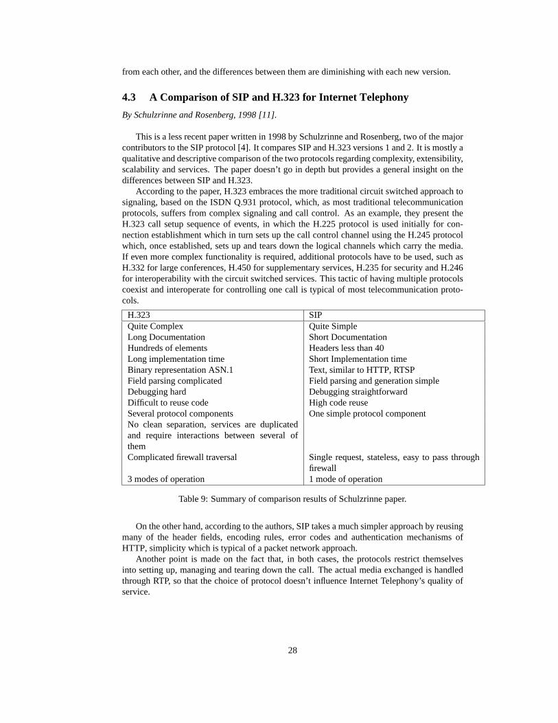
4.3 A Comparison of SIP and H.323 for Internet Telephony
By Schulzrinne and Rosenberg, 1998 [11].
This is a less recent paper written in 1998 by Schulzrinne and Rosenberg, two of the majorcontributors to the SIP protocol [4]. It compares SIP and H.323 versions 1 and 2. It is mostly aqualitative and descriptive comparison of the two protocols regarding complexity, extensibility,scalability and services. The paper doesn’t go in depth but provides a general insight on thedifferences between SIP and H.323.
According to the paper, H.323 embraces the more traditional circuit switched approach tosignaling, based on the ISDN Q.931 protocol, which, as most traditional telecommunicationprotocols, suffers from complex signaling and call control. As an example, they present theH.323 call setup sequence of events, in which the H.225 protocol is used initially for con-nection establishment which in turn sets up the call control channel using the H.245 protocolwhich, once established, sets up and tears down the logical channels which carry the media.If even more complex functionality is required, additional protocols have to be used, such asH.332 for large conferences, H.450 for supplementary services, H.235 for security and H.246for interoperability with the circuit switched services. This tactic of having multiple protocolscoexist and interoperate for controlling one call is typical of most telecommunication proto-cols.
H.323 SIPQuite Complex Quite SimpleLong Documentation Short DocumentationHundreds of elements Headers less than 40Long implementation time Short Implementation timeBinary representation ASN.1 Text, similar to HTTP, RTSPField parsing complicated Field parsing and generation simpleDebugging hard Debugging straightforwardDifficult to reuse code High code reuseSeveral protocol components One simple protocol componentNo clean separation, services are duplicatedand require interactions between several ofthemComplicated firewall traversal Single request, stateless, easy to pass through
firewall3 modes of operation 1 mode of operation
Table 9: Summary of comparison results of Schulzrinne paper.
On the other hand, according to the authors, SIP takes a much simpler approach by reusingmany of the header fields, encoding rules, error codes and authentication mechanisms ofHTTP, simplicity which is typical of a packet network approach.
Another point is made on the fact that, in both cases, the protocols restrict themselvesinto setting up, managing and tearing down the call. The actual media exchanged is handledthrough RTP, so that the choice of protocol doesn’t influence Internet Telephony’s quality ofservice.
28

The authors conclude that SIP provides a similar set of services to H.323, but providesfar lower complexity, rich extensibility, and better scalability. They point out that future workis due to more fully evaluate the protocols, and examine quantitative performance metrics tocharacterize these differences. They also imply that a study measuring the processing overheadof SIP and H.323, would be quite useful.
29

5 Planned Work
By studying three major comparative analyses [9, 10, 11] of H.323 and SIP and an analy-sis of the call setup delay in IP telephony citeeyers00:delay, it became apparent that there isneed for further measurements and quantitative comparison results. The two protocols havebeen compared in a fairly comprehensive manner regarding services supported, extensibility,complexity, functionality and interoperability issues. However, when it comes to Quality ofService, Scalability and Resource utilization and management, the results tend to be based onthe intuitive and expected protocol behaviours.
It seems as a logical extension to supplement this work with a rigorous and thorough com-parative analysis of H.323 and SIP on the aspects of quality of service, scalability and resourceutilization and management. We have followed the guidelines in [12] to perform our perfor-mance analysis.
5.1 Assumptions
In this comparison, we will only focus on H.323v4, and we will use the most efficient way forcall setup that this version provides. We will ignore any issues involving the actual transferof media, since it is irrelevant in both protocols for the call setup. We will be referring to thewhole duration of the multimedia call between two or more users as ”multimedia session” orplainly ”session”.
5.2 Goals
In order to compare H.323 and SIP, the following aspects of each protocol will be evaluatedand then we will compare the corresponding metrics between two protocols. We always referto per session metrics.
1. Call Setup Delay
• How long is it?
• How is it affected by the transport protocol (TCP or UDP)?
• How is it affected by the current load of the intervening protocol entities?
2. CPU and Memory Requirements
• Measure the CPU time for the execution of the protocol at the terminal.
• Measure the aggregate CPU time for the execution of the protocol at all the inter-vening protocol entities.
• Measure the aggregate CPU time for the execution of the protocol at all the inter-vening protocol entities and the participating terminals.
• How is the CPU load affected by:
– Tokenization– Compression after tokenization– Preservation of states
3. Network Resources
• How much bandwidth is consumed?
30
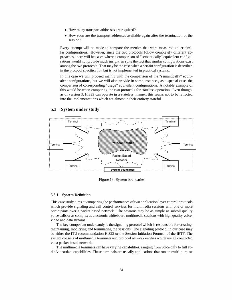
• How many transport addresses are required?
• How soon are the transport addresses available again after the termination of thesession?
Every attempt will be made to compare the metrics that were measured under simi-lar configurations. However, since the two protocols follow completely different ap-proaches, there will be cases where a comparison of ”semantically” equivalent configu-rations would not provide much insight, in spite the fact that similar configurations existamong the two protocols. That may be the case when a certain configuration is describedin the protocol specification but is not implemented in practical systems.
In this case we will proceed mainly with the comparison of the ”semantically” equiv-alent configurations, but we will also provide in some instances, as a special case, thecomparison of corresponding ”usage” equivalent configurations. A notable example ofthis would be when comparing the two protocols for stateless operation. Even though,as of version 3, H.323 can operate in a stateless manner, this seems not to be reflectedinto the implementations which are almost in their entirety stateful.
5.3 System under study
System BoundariesTerminal
Terminal
Terminal
Terminal
Terminal
Terminal
Packet BasedNetwork
Protocol Entities
Figure 18: System boundaries
5.3.1 System Definition
This case study aims at comparing the performances of two application layer control protocolswhich provide signaling and call control services for multimedia sessions with one or moreparticipants over a packet based network. The sessions may be as simple as subtoll qualityvoice calls or as complex as electronic whiteboard multimedia sessions with high quality voice,video and data streams.
The key component under study is the signaling protocol which is responsible for creating,maintaining, modifying and terminating the sessions. The signaling protocol in our case maybe either the ITU recommendation H.323 or the Session Initiation Protocol of the IETF. Thesystem consists of multimedia terminals and protocol network entities which are all connectedvia a packet based network.
The multimedia terminals can have varying capabilities, ranging from voice only to full au-dio/video/data capabilities. These terminals are usually applications that run on multi-purpose
31

computers or on specialized hardware and act as agents on behalf of the user by issuing andresponding to protocol requests.
The protocol network entities are applications running on various machines scattered aroundthe network, whose cooperation is essential for the implementation of the protocol between twoor more terminal endpoints.,
The multimedia terminal endpoints, the protocol entities along with the underlying networkthat interconnects them constitute the system under study.
5.3.2 Services
The system provides signaling and call control services for multimedia sessions between end-point terminals with varying capabilities. In other words, the system is responsible of estab-lishing, managing and terminating multimedia calls between two or more terminal endpoints.
Specifically, we can summarize the services provided by the system as follows.
(a) User Location Discovery.Determination of the endpoint terminal where the user can bereached.
(b) User Availability. Determination of the user’s willingness to engage in communicationwith the calling party.
(c) Terminal Capabilities Exchange.Determination of a minimum common set of capabili-ties required for the call to proceed.
(d) Call Setup.Establishment of a connection between two or more users and setup of therequested/required media channels.
(e) Call Management.Management of an ongoing call by adding/removing endpoints inthe conversation and setting up additional media channels.
(f) Call Termination.Termination of the call session.
Among the servicesnot provided by the system, we should mention the following.
• Resource Reservation.The system does not provide any means for reserving the requirednetwork resources for either the call setup or the media channel setup.
• Media Transfer.The system is responsible for setting up and controlling the multimediacall as well as preparing and negotiating the nature of the requested media channels.However, the actual exchange of the media is not handled by the system itself, as definedin our case study.
5.3.3 Metrics
For each signaling protocol, we will compare the response times, the throughputs and theresources consumed. The resources involved in our system are the computers on which theterminals and the protocol entities run and the network links that interconnect them. Thisleads to the following performance metrics:
I. Response Time
(a) Call Setup Delay.This delay is defined as the interval between the completionof the call request operation by the user (for a conventional telephone or ISDNnetwork this would be the last dialed digit) and receiving ringback.
32

(b) Dial-to-Ring DelayThis delay is informally defined in [13] as the interval betweenthe completion of the call request operation by the user and the moment the callee’sterminal rings. The definition is quite vague however, since the signaling protocolcan start ringing multiple terminals where the user might be either sequentially orin parallel. – Needs further study
II. Throughput
(a) CPU time at terminal.This metric represents the CPU cycles spent, per session,for implementing the signaling protocol at the terminal.
(b) CPU time at protocol entity.This metric represents the CPU cycles spent, persession, for implementing the signaling protocol at a protocol entity.
(c) Aggregate CPU time at protocol entities.This metric represents the CPU cyclesspent, per session, for implementing the signaling protocol across all the interven-ing protocol entities.
(d) Total CPU time.This metric represents the CPU cycles spent, per session, for im-plementing the signaling protocol across all terminal endpoints and the interveningprotocol entities.
III. Resources
(a) Bytes Exchanged.This includes all packets used by the signaling protocol, persession.
(b) Reserved Transport Addresses.This pertains to the number of transport addressesreserved, per session at the terminals and the intervening protocol entities.
(c) Reuse hysteresis of Transport Addresses.Whenever a session terminates, the trans-port addresses it used are not available for reuse immediately. This metric repre-sents the delay between the session termination and the moment the resource isavailable again.
This may not make much sense. I haven’t found any reference discussing this issue,but it seems reasonable to me to look into it a little bit further.
5.3.4 System Parameters
The system parameters that affect the performance of a given signaling protocol, can be sum-marized as follows:
(a) Speed of terminal CPU and available memory
(b) Speed of protocol entity CPU and available memory
(c) Specific implementation of signaling protocol
(d) Operating system overhead for interfacing with the network
(e) Speed of the network
33

5.3.5 Workload Parameters
The workload parameters that affect the performance are the following:
I. Signaling Protocol
(a) Type of signaling protocol.The approach of each signaling protocol may result inincreased or decreased workload for equivalent session signaling.
(b) Type of transport protocol.Since a reliable transport protocol, such as TCP, isdesigned to provide its services to a vast variety of applications, its parameterscould not be possible fine tuned for every application. Thus, if an applicationuses instead, an unreliable transport protocol such as UDP and relies on its owncustomized retransmission scheme for reliability, then the delay performance isexpected to be much better.In our case, it would be interesting to study the performance of the two protocolsin the case of UDP combined with a retransmission scheme to ensure reliabilitywhenever it is explicitly required by the protocols.
(c) Level of compression.Signaling messages can be compressed before transmitted,thus decreasing the amount of traffic exchanged between the terminals and theprotocol entities.It would be interesting to study the tradeoff between smaller traffic and highercomputation at the terminals and the protocol entities.
(d) Number of protocol entities involved.In all but the most basic session configura-tions there is need for at least one intervening protocol entity.It would be desirable to study the effect of an increasing number of interveningentities in each protocol.
(e) Signaling protocol routing scheme.Both protocols provide a few alternatives forthe routing of the signaling messages (directly between endpoints or through inter-vening entities). The actual scheme used may be dictated by the need for a specificfeature or imposed by billing or political reasons.Either way, it would be desirable to compare how each protocol performs withdifferent routing schemes.
(f) Signaling protocol mode of operation.Both protocols support either stateless orstateful operation. By intuition we could argue that a stateless operation results ina higher call throughput for the intervening protocol entities. However, it is notclear how much overhead is added to the terminals, which in some cases may havecomputational and storage limitations. Furthermore, even though a protocol mayhave provisions for operating in a stateless manner, it may not enforce it in practice(H.323 for example).For all those reasons, it would provide us with insight to study the behaviour of thesystem under different modes of operation.
(g) Security measures.Without any security provisions, the messages in both pro-tocols face the risk of being intercepted, modified, dropped or duplicated. Theobvious solution is to apply security mechanisms to ensure integrity, privacy andnon-maleability of the messages. It would be interesting to compare how the over-head of such mechanisms affect the performance of each protocol.
34

II. Call Session
(a) Time between calls.Usually this metric follows a certain distribution that can bemodeled after the behaviour of users in the telephone network, since in our studywe are mostly concerned with calls made by human users.
(b) Duration of call session.This metric follows a certain distribution which can bespeculated by comparing the corresponding distribution of the calls in a telephonenetwork and taking into account the broader capabilities of the call (in contrast tothe voice-only capability of the PSTN).
(c) Session participation.This metric represents the number of participants in the callsession. We are interested in evaluating the effect of this number on the perfor-mance of each protocol.
(d) Session characteristics.This metric is used to convey the type of the call session.In both cases, the signaling protocol messages do not vary much, whether the callsession comprises only of one voice channel or numerous multimedia streams. Theprotocol is not responsible for the transport of the media streams; it merely sets upand prepares the various channels for transport. However, it would be desirable toevaluate the effect of different session types in each protocol.
(e) Characteristics modifications at mid-session.This metric represents the modifica-tions that may happen to the call session after it has been established.
III. Other Loads
(a) Other CPU load at terminal and protocol entitiesWe must take into considerationthat the CPU is not devoted entirely to implementing the signaling protocol.
(b) Other load on the networkWe must take into consideration, that along with thesignaling protocol network traffic, we have also other unrelated traffic.
5.3.6 Factors
The key factors, selected among the system and workload parameters which we wish to vary,are the following:
1. Type of signaling protocol.Two types of signaling protocols, H.323 and SIP will becompared.
2. Level of compression.The messages exchanged between the terminals and protocolentities that implement the protocol can be exchanged in compressed form. We willstudy the effect of using this method.
• For H.323 we will use two levels:
(a) No compression
(b) Compression
• For SIP we will use three levels:
(a) No compression
(b) Compression
(c) Compression after tokenization
35

3. Number of protocol entities involved.Both protocols can work without intervening pro-tocol entities. However, most useful configurations require the cooperation of at leastone protocol entity.
Four levels will be used. One, two, four and six entities.
4. Signaling protocol routing scheme.Both protocols provide different alternatives for therouting of signaling messages through the protocol entities.
• For H.323 we will use three levels:
(a) Gatekeeper routedcall signaling H.225with gatekeeper routedcontrol channel H.245.
(b) Gatekeeper routedcall signaling H.225with direct control channel H.245.
(c) Direct endpoint call signaling H.225anddirect control channel H.245
• For SIP we will use two levels:
(a) Signaling routed through SIP proxy server.
(b) Direct endpoint signaling.
5. Signaling protocol mode of operation.We will use two levels, stateless and statefulmode of operation, which are supported by both protocols.
6. Speed of the network.Since the speed of the network is directly dependent on the dis-tance between endpoints, three levels of distance will be used between endpoint termi-nals involved in the session.
(a) Short distance (in campus)
(b) National long distance (across countries)
(c) International long distance (across continents).
7. Time between callswill follow an appropriate distribution – still under study.
8. Duration of callswill follow an appropriate distribution – still under study.
9. Characteristics of calls.The call sessions we are concerned with can involve any numberof audio/video/data channels. Three levels will be used:
(a) Low complexity,voice only sessions.
(b) Medium complexity,voice and low quality video sessions.
(c) High complexity,full fledged multimedia session.
10. Session participation.The participants in a call session can be two or more. We willbe concerned with two levels of user participation. Call sessions between two users andsessions between four users.
36

5.4 Next Steps
1. Consider and document which combination of methods to use: analytical modelling,measurements or simulation. It seems very plausible to take measurements since realsystems exist and are accessible. Perhaps it would be a good idea to investigate furtherthe analytical part, just for gaining some experience in modelling a real system? Itwill probably not yield tangible results, but it might expose major inefficiencies of theprotocols.
2. Create and document a measurement testbed. The objective is to set up limited real SIPand H.323 networks, decide on a traffic model for the number of incoming calls andtheir duration, supply the input to the real system and take measurements. The testbedwould probably comprise of applications performing the tasks of the terminal endpointsand a few server applications residing on different machines for the intervening entities.We may want to run corresponding entities of the two protocols on the same machinesand supply identical traffic to the two networks (SIP and H.323) simultaneously. Forexample we may have a server in Maryland, a server in Greece and have endpoints com-municate between all sites (MD¡-¿GR, MD¡-¿MD, GR¡-¿GR, GR¡-¿MD). The measure-ments will be highly dependent on the time of day and also from possible downtimes ofthe interconnecting networks. But it is a starting point. –Needs more work
37

6 Measuring SIP and H.323 call setup delay
This section outlines the experiments needed to measure the call setup delay of the SIP andH.323 control protocols in the context of a real system in a WAN environment. These mea-surements will be subsequently used to compare the two control protocols.
Zone A
IPNetworkdomain
Domain A
H.323Gatekeeper H.323
Terminal
H.323Terminal
SIP User Agent(at home)
SIP ServerRegistrar/
Proxy/Redirect
SIP User Agent(at home)
Zone B
IPNetworkdomain
Domain B
H.323GatekeeperH.323
Terminal
H.323Terminal
SIP User Agent(visiting from A)
SIP ServerRegistrar/
Proxy/Redirect
SIP User Agent(at home)
IPNetwork
Figure 19: Testbed - General view
Our course of action will be to create initially two SIP domains and two H.323 zones, withalmost equivalent entities and a pool of user agents/terminals in each case. Then, accordingto a traffic generation scheme, the user agents/terminals will be instructed to attempt to placecalls to other agents/terminals and emulate a call session without actually transferring anymedia content.
In each case, we will be measuring the call setup delay, the distribution of the interarrivaltimes, the sizes and types of requests to each of the intervening entities (proxy servers for SIP,gatekeepers for H.323) as well as the distribution of the UDP roundtrip delay and UDP lossesbetween the two domains/zones.
6.1 Measuring SIP call setup delay
This experiment aims at measuring in an emulated real system the call setup delay incurredby the SIP control protocol. Our main goal is not to estimate an absolute value for the delay,but a relative value against which to compare SIP and H.323. This value can also be used tocompare various modes of operation within SIP, such as stateful vs stateless operation, varyingnumber of intermediate proxies, etc.
Since we will be taking measurements in a WAN environment, it is expected that the valuesmeasured will be statistically correlated to the behaviour of the UDP roundtrip delay and UDPlosses. Therefore, any comparisons of different experiments should be made only when theUDP traffic patterns are highly correlated.
Another interesting point would be to determine if there is a point in the system’s operation,beyond which the behaviour of the call setup delay deviates from the behaviour of the UDPtraffic.
38

In this experiment we are solely concerned about the behaviour of the control protocol, i.e.,we only generate the required traffic on the control channel used to setup a media call betweentwo endpoints. Our system doesn’t generate the actual media traffic exchanged between theterminals, since it doesn’t affect the call setup delay in any way.
6.1.1 Testbed
The measurement testbed comprises of two SIP proxy/registrar servers connected through aWAN and two groups of user agents, each on the same LAN as the SIP servers. All callsshould be routed through the SIP proxies which are stateful, i.e. they retain state informationabout the call requests they receive.
WANSIP
ServerSIP
Server
UserAgent
UserAgent
UserAgent
UserAgent
LAN
UserAgent
UserAgent
UserAgent
UserAgent
LAN
ControllingApplication
Controls the experiment:- Starts/Stops UAs- Starts/Stops SIP servers- Monitors UDP losses/roundtrip delays- Collects and processes statistics
Domain isr.umd.edu Domain di.uoa.gr
Figure 20: SIP Testbed
SIP Servers The SIP servers use location servers (in our case just an sql database) to deter-mine how they should process an incoming call setup request. According to the SIP specifi-cation, the server can act either as a proxy or a redirect server. In the case of a proxy server,the request is forwarded to the suitable user agent if the agent is registered with the currentproxy (regardless of whether it is in its home domain or just visiting). Otherwise, the requestis forwarded to the agent’s domain sip proxy server.
On the other hand, if the sip server acts as a redirect server, then instead of forwarding therequest, it returns a list of locations (sip servers or user agents) where the user agent can befound. In this case, it is up to initiating client to forward requests to the new locations. A sipserver determines whether to act as a proxy or a redirect server based on configuration settingsand directions specified by each user agent during registration.
SIP User Agents Each user agent acts on behalf of a user by placing and receiving mediacalls to and from other user agents. There is no media content exchanged between the useragents, just control messages. Other than the absence of media content, the call will proceed
39

normally. A user agent initiating the call will issue through it’s outbound proxy server an invi-tation to a call session, then the server will proxy the request the suitable user agent, forwardit to another proxy server or return a list of new locations to try.
Once the call is established, the user agent essentially remains idle for the duration of thecall, since in general only media content is exchanged during this time. However, control trafficmay be generated if the call characteristics need to be modified in any way (inviting a thirdparty, altering media channels) or the user agent is responding to new call session invitations(either by placing them in a queue or rejecting them).
In our testbed the users are emulated by a controlling application which will be instructingthe user agents to place calls according to a certain distribution for the time between calls aswell as the duration of the call.
6.1.2 Implementation
Since we are performing measurements of a real system, our results will rely heavily on theimplementation. We will be using software from the University of Columbia, where SIP orig-inated, as well as our own software to implement minimal user agents and the controllingapplication.
SIP Servers We are using the sipd SIP server from Columbia. This is a complete imple-mentation of the specification and can be instructed to keep detailed log files which serves ourpurpose. The server uses a MySql database server for its location service. It has been installedsuccessfully on the isr.umd.edu domain but not yet on the di.uoa.gr domain.
SIP User Agents The initial attempt to use sipc, the SIP user agent from columbia failed.The code is changing continuously and it uses too many other packages for the media sup-port. It turned out that it was not worth the effort and a complete waste of time, since in ourexperiment we are not concerned at all with the media transfer.
Since the solution from Columbia was abandoned, it was necessary to write our own useragent client/server. These user agents should abide at least to the minimal requirements of theSIP standard. Because of the textual nature of the SIP standard the applications are not toohard to write. Basic support should be provided, i.e. support for the requests INVITE, ACK,SDP, BYE and the response classes 1xx, 2xx, 3xx, 4xx, 5xx, 6xx.
Furthermore, the agents contain the added functionality of continuously placing calls ac-cording to an exponential distribution for the time between calls as well as the duration ofthe calls. They also perform complete logging of the SIP activity. However, no support forhandling media is provided.
Controlling application This is not related to the standard, but is used to control the wholeexperiment. It performs the following tasks:
• Starts and stops the user agents in all locations
• Starts and stops the SIP servers in all locations
• Collects statistics about UDP losses and roundtrip delay between the two domains.
• At the end of the experiment it processes the statistics from the various entities.
40

6.1.3 Measurements
We are interested in the following measurements:
• Call setup delay .The main metric we wish to evaluate and use for comparing SIP withH.323 as well as various modes of operations of SIP.
• Distribution of UDP losses and roundtrip delay.We need this in order to make faircomparisons. Furthermore, the call setup delay should be closely correlated and anydeviation should be properly explained.
• Distribution of interarrival times of call requests.
• Distribution of packet sizes of call requests.
Assumptions In this experiment, we assume the following:
1. SIP control protocol.
2. UDP for packet transport.
3. Two SIP servers serving two domains connected through a WAN.
4. The SIP servers are stateful.
5. Calls will have only two participants
6. Call session characteristics will be typical, i.e. involving one audio and one low-bitratevideo media channel. Even though we are not concerned with the media content, wemust handle the negotiation of the session characteristics, since they are part of the callsession control.
Scenarios The following scenarios will be used:
1. Only agents in domainA place calls to agents in domainB, no requests will be redirectedand all agents in domainB are in their home domain.
2. Only agents in domainA place calls to agents in domainB, no requests will be redirectedbut some agents in domainA are visiting from domainB (i.e. Any calls to these agentsfrom domainA, will be served locally by the proxy server of domainA).
In these scenarios, two levels of compression will be used:
• No compression
• Tokenization (substituting long field names with one letter codes)
The number of user agents on each side will be: 20, 40, 60, 80, 100
41

References
[1] I. T. Union, “Packet-based multimedia communication systems,” TelecommunicationStandardization Sector of ITU, Geneva, Switzerland, Recommendation H.323, Nov. 172000.
[2] ——, “Abstract Syntax Notation One (ASN.1): Specification of basic notation,”Telecommunication Standardization Sector of ITU, Geneva, Switzerland, Recommen-dation X.680, Dec. 1997.
[3] H. Schulzrinne, S. Casner, R. Frederick, and V. Jacobson, “RTP: A Transport Protocolfor Real-Time Applications,” Internet Engineering Task Force, Request For Comments1889, Jan. 1996, proposed Standard.
[4] M. Handley, H. Schulzrinne, E. Schooler, and J. Rosenberg, “SIP: Session InitiationProtocol,” Internet Engineering Task Force, Request For Comments 2543, Mar. 1999,proposed Standard.
[5] M. Handley and V. Jacobson, “SDP: Session Description Protocol,” Internet EngineeringTask Force, Request For Comments 2327, Apr. 1998, proposed Standard.
[6] A. B. Johnston,SIP: Understanding the Session Initiation Protocol. Artech House,2001.
[7] J. Rosenberg and H. Schulzrinne, “The IETF internet telephony architecture and proto-cols,” IEEE Network, vol. 13, no. 3, pp. 18–23, May / June 1999.
[8] T. J. Kostas, M. S. Borella, I. Sidhu, G. M. Schuster, J. Grabiec, and J. Mahler, “Real-Time Voice Over Packet-Switched Networks,”IEEE Network, vol. 12, no. 1, pp. 18–27,Jan. 1998.
[9] N. Networks, “A Comparison of H.323v4 and SIP,” 3GPP S2, Tokyo, Japan, TechnicalReport S2-000505, Jan. 5 2000.
[10] I. Dalgic and H. Fang, “Comparison of H.323 and SIP for IP Telephony Signaling,”in Proceedings of SPIE. Multimedia Systems and Applications II, ser. Proceedings ofPhotonics East, Tescher, Vasudev, Bove, and Derryberry, Eds., vol. 3845. Boston,Massachusetts. USA: The Internationl Society for Optical Engineering (SPIE), Sept. 20-22 1999.
[11] H. Schulzrinne and J. Rosenberg, “A Comparison of SIP and H.323 for Internet Tele-phony,” in Proceedings ofThe 8th International Workshop on Network and OperatingSystems Support for Digital Audio and Video (NOSSDAV 98), Cambridge, UK, July 8-101998, pp. 83–86.
[12] R. Jain,The Art of Computer Systems Performance Analysis. John Wiley & Sons, Inc,Dec. 1991.
[13] T. Eyers and H. Schulzrinne, “Predicting Internet Telephony Call Setup Delay,” inPro-ceedings of the 1st IP-Telephony Workshop (IPtel 2000), Berlin, Germany, Apr. 12-132000.
42