a biorobotic model of the suction-feeding system in
TRANSCRIPT

A biorobotic model of the suction-feedingsystem in largemouth bass: the roles of
motor program speed and hyoid kinematicsThe Harvard community has made this
article openly available. Please share howthis access benefits you. Your story matters
Citation Kenaley, Christopher P., and George V. Lauder. 2016. A BioroboticModel of the Suction-Feeding System in Largemouth Bass: TheRoles of Motor Program Speed and Hyoid Kinematics. The Journalof Experimental Biology 219, no. 13: 2048–2059. doi:10.1242/jeb.132514.
Published Version doi:10.1242/jeb.132514
Citable link http://nrs.harvard.edu/urn-3:HUL.InstRepos:30650482
Terms of Use This article was downloaded from Harvard University’s DASHrepository, and is made available under the terms and conditionsapplicable to Other Posted Material, as set forth at http://nrs.harvard.edu/urn-3:HUL.InstRepos:dash.current.terms-of-use#LAA

RESEARCH ARTICLE
A biorobotic model of the suction-feeding system in largemouthbass: the roles of motor program speed and hyoid kinematicsChristopher P. Kenaley*,‡ and George V. Lauder
ABSTRACTThe vast majority of ray-finned fishes capture prey through suctionfeeding. The basis of this behavior is the generation of subambientpressure through rapid expansion of a highly kinetic skull. Over thelast four decades, results from in vivo experiments have elucidatedthe general relationships between morphological parameters andsubambient pressure generation. Until now, however, researchershave been unable to tease apart the discrete contributions of, andcomplex relationships among, the musculoskeletal elements thatsupport buccal expansion. Fortunately, over the last decade,biorobotic models have gained a foothold in comparative researchand show great promise in addressing long-standing questions invertebrate biomechanics. In this paper, we present BassBot, abiorobotic model of the head of the largemouth bass (Micropterussalmoides). BassBot incorporates a 3D acrylic plastic armature of theneurocranium, maxillary apparatus, lower jaw, hyoid, suspensoriumand opercular apparatus. Programming of linear motors permitsprecise reproduction of live kinematic behaviors including hyoiddepression and rotation, premaxillary protrusion, and lateralexpansion of the suspensoria. BassBot reproduced faithfulkinematic and pressure dynamics relative to live bass. We showthat motor program speed has a direct relationship to subambientpressure generation. Like vertebrate muscle, the linear motors thatpowered kinematics were able to produce larger magnitudes of forceat slower velocities and, thus, were able to accelerate linkages morequickly and generate larger magnitudes of subambient pressure. Inaddition, we demonstrate that disrupting the kinematic behavior of thehyoid interferes with the anterior-to-posterior expansion gradient.This resulted in a significant reduction in subambient pressuregeneration and pressure impulse of 51% and 64%, respectively.These results reveal the promise biorobotic models have for isolatingindividual parameters and assessing their role in suction feeding.
KEY WORDS: Fish, BassBot, Robotics, Pressure
INTRODUCTIONThe majority of ray-finned fishes (actinopterygians) capture preyby suction feeding, a behavior dependent on the generation ofsubambient pressure through rapid expansion of the buccal cavity(Fig. 1). For nearly half a century, the biomechanical basis of aquaticsuction feeding in fishes has attracted the attention of comparativebiologists. As a result, there exists a generalized understanding of thefunctional role played by major musculoskeletal units of the teleost
head (for reviews, see Ferry-Graham and Lauder, 2001; Westneat,2005; Day et al., 2015). Rapid expansion of the buccal cavity resultsfrom orchestrated movements of linkages that form a highly kineticskull, including rotation of the lower jaw, ventral rotation anddepression of the hyoid apparatus, lateral expansion of thesuspensoria, and dorsal rotation of the cranium about the axialskeleton (Alexander, 1967; Lauder, 1980a, 1985).
This model of suction feeding is based largely on data from in vivoexperimentation on a number of ray-finned fishes, in addition tomorerecent work on selected elasmobranchs (e.g. Motta and Wilga, 2000;Nauwelaerts et al., 2008; Wilga and Sanford, 2008). Feedingsequences of live animals have been analyzed for kinematic, pressureand water-flow patterns, as well as other variables linked to suctionperformance (e.g. Grubich and Wainwright, 1997; Lauder et al.,1986; Sanford and Wainwright, 2002; Day et al., 2007). As acomplement to in vivo experimentation, a few studies have involvedcomputational models of the teleost suction-feeding system (e.g.Carroll et al., 2004; Drost et al., 1988; Holzman et al., 2012; Osse andMuller, 1980; Van Wassenbergh and Aerts, 2009), and surgicalalterations of head morphology have provided further insights intothe functional relationships among mechanical linkages (e.g. Lauder,1980b, 1983; Liem, 1970). As a whole, experimental and modelingapproaches have yielded important insights into the mechanisticrelationships between morphological parameters and suctionperformance. Despite this, there remain fundamental questionssurrounding several aspects of suction feeding in ray-finned fishes.Because of the complexity of the interactions among the manyskeletal and muscular elements of the head, it has provenexceptionally difficult to tease apart the contributions of individualmechanical linkages to suction-feeding performance. In particular,the relationship between the complex motion of musculoskeletalelements in the head and negative pressure generation inside thebuccopharyngeal cavity, as well as the discrete contributions tosuction generation of each musculoskeletal unit, is still not clear(Sanford andWainwright, 2002;Wainwright et al., 2007). To addressquestions such as these and understand the influence of individualcomponents of suction-feeding systems of fishes, it is clear that a newline of attack is required. Studies of feeding systems in live animalsare limited in their ability to determine causal relationships betweenkinematics and suction performance.
Fortunately, a promising avenue of research in vertebratebiomechanics has risen to the fore over the last decade: bioroboticmodels. Based on abstractions of morphological details and precisemotion programs, biorobotic models of vertebrate musculoskeletalsystems permit isolation of individual parameters and evaluation ofa broad parameter space. The application of biorobotic models hasproven particularly illuminating in the study of fish locomotorsystems and aquatic propulsion, permitting researchers to evaluatehow fishes generate thrust, the manner of hydrodynamic interactionsbetween sets of fins, and how inherent material properties andkinematic programs affect locomotor efficiency (Esposito et al.,Received 23 September 2015; Accepted 21 April 2016
Museum of Comparative Zoology, Harvard University, Cambridge, MA 02138, USA.*Present address: Department of Biology, Boston College, Chestnut Hill, MA 02467,USA.
‡Author for correspondence ([email protected])
C.P.K., 0000-0003-3832-7001
2048
© 2016. Published by The Company of Biologists Ltd | Journal of Experimental Biology (2016) 219, 2048-2059 doi:10.1242/jeb.132514
Journal
ofEx
perim
entalB
iology

2012; Lauder et al., 2007, 2011). Perhaps as a result of the skeletaland kinematic complexity of the actinopterygian head, nobiorobotic models have been developed for any fish feedingsystem. The development of robotic feeding models will permitscientists to study feeding in novel ways. Comparative studies offeeding in fishes, although likely to continue yielding valuable data,are limited by an inability to control non-feeding variables thatdiffer between species and an inability to isolate any onemorphological variable. In addition, in vivo experimentation isoften confounded by idiosyncratic feeding behavior (e.g. loss ofmotivation during feeding; Lauder, 1980b).In this paper, we present the design of ‘BassBot’, a first-
generation biorobotic model of the ray-finned fish suction-feedingsystem based on the morphology of the largemouth bass(Micropterus salmoides Lacépede). BassBot incorporates a 3Darmature of the bass head fabricated from acrylic plastic. The hardanatomy of the model represents the functional units of theactinopterygian head including the neurocranium, maxillaryapparatus, lower jaw, hyoid, suspensorium and opercularapparatus (Fig. 1). Constrained by the properties and positions ofjoints found in the bass skull and actuated by motors representingthe muscles that power buccal expansion, the 3D kinematic profilesof these units are precisely controlled. Programming of motorspermits precise simulation of kinematic behaviors, including hyoiddepression and rotation, premaxillary protrusion, and lateralexpansion of the suspensoria. The goal of developing thisprototype was to fabricate a robotic system that producesbehaviors generally similar in kinematics and negative-pressuregeneration to those of a largemouth bass. We simultaneously set outto demonstrate the promise of biorobotic feeding models by firstcomparing model behavior and pressure performance with dataobtained from in vivo feeding experiments in unrestrained bass, andthen addressing several longstanding questions in suction feedingthrough experiments that isolate and alter model parameters. Our
specific experimental goals were (1) to evaluate the relationshipbetween the speed of buccal expansion and suction performance,and (2) to assess the contribution of the hyoid apparatus tosubambient pressure generation.
MATERIALS AND METHODSStudy species and specimensOur robotic system was modeled after the largemouth bass, aspecies readily available in collections and from commercialsources. This facilitated easy acquisition of specimens formorphological characterization and feeding experiments. Inaddition, this species has been the subject of previous analyses,including the classic paper by Nyberg (1971) and a number ofstudies that evaluated the functional role of musculoskeletal units infeeding (e.g. Camp and Brainerd, 2014; Camp et al., 2015; Lauder,1983; Richard and Wainwright, 1995; Wainwright and Richard,1995) and several that explored the relationship betweenmusculoskeletal morphology, kinematics and suction generation(e.g. Carroll et al., 2004; Grubich and Wainwright, 1997; Highamet al., 2006a,b). Thus, the choice of this species permittedmanageable integration of morphological data with kinematic,behavioral and pressure performance data that together informedthe design requirements of our robotic model.
Feeding experiments were based on three individuals (14.7, 18.4and 19.9 cm standard length, SL) purchased from WiiningAquaculture (Gardner, MA, USA), and kept in individual 40 laquaria under a 12 h:12 h light:dark cycle. Fish were fedearthworms daily until 2–3 days before feeding experiments. Fishwere handled ethically according to Harvard University InstitutionalAnimal Care and Use Committee guidelines, protocol 20-03.
Morphological data for model design came from analyses ofpreserved specimens. A 3D model of the skeletal structure of asingle specimen, MCZ (Museum of Comparative Zoology,Harvard University) 48917 (17.8 cm SL), was reconstructed
A
B
C
i
E
ljbh
ur
qu
ii
D
lj
pm
bhur
or
qupm
Fig. 1. The species modeled in robot development, thelargemouth bass (Micropterus salmoides). (A–C) Theskeletal units of the cranium with left lower jaw, suspensoriumand opercular apparatus removed. Black arrows represent thetypical kinematic trajectories during suction feeding.Neurocranium, blue; maxillary apparatus, red; lower jaw, yellow;hyoid apparatus, purple; opercular apparatus, orange; pectoralgirdle, green. (A) Left-lateral view, (B) anterior view and (C)ventral view. (D) Lateral and (E) ventral frames captured fromhigh-speed videography of a feeding experiment withlandmarks indicated by red dots: anteroventral tip of the lowerjaw (lj), anterior-most point of the premaxilla (pm), ventral-mostpoint along the fleshy orbit (or), ventral margin of the quadrate(qu) between the quadrato-articular joint and anteroventral tip ofthe preopercle, anterior basihyal (bh) and anterior urohyal (ur).
2049
RESEARCH ARTICLE Journal of Experimental Biology (2016) 219, 2048-2059 doi:10.1242/jeb.132514
Journal
ofEx
perim
entalB
iology

from micro-computed tomography (µCT) analysis (Fig. 1A–C).Scan parameter values for amperage, voltage, exposure time andimage rotation were 60 µA, 130 kV, 625 ms and 0.5 deg,respectively. The scan produced images with a voxel size of38 µm. After slice reconstruction in NRecon (Micro Photonics,Inc., Allentown, PA, USA), volume was rendered in Mimics 15.0(Materialise, Leuven, Belgium). Additional skeletal data wereobtained from a 21.2 cm skeletonized specimen (MCZ 154227).Muscle geometry, including positions of origin and insertion,was recorded from dissections of four specimens (MCZ 48917,15.3–19.4 cm SL).
Feeding kinematicsThe motions of musculoskeletal units of the bass feeding systemwere studied by filming each of three individuals with two PhotronFastcam PCI-2014 cameras (resolution: 1024×1024 pixels;Photron, San Francisco, CA, USA) in lateral and ventral views.Both cameras filmed at a rate of 1000 frames s−1 and were digitallysynchronized. Each bass was fed five times over the course of asingle series of trials in a 28×28×80 cm (width×depth×length) tankfor a total of 15 trials. Feedings were initiated at approximately10 min intervals by dropping a small (1.5 cm) piece of earthwormthrough a tube 2.5 cm in diameter.For each trial, six points on the bass head were digitized in lateral
and ventral views (Fig. 1D–E): anteroventral tip of the lower jaw (1),anterior-most point of the premaxilla (2), ventral-most point along thefleshy orbit (3), ventral margin of the quadrate between the quadrato-articular joint and anteroventral tip of the preopercle (4), anteriorbasihyal (5) and anterior urohyal (6). These points were digitallycalibrated with Hedrick’s (2008) custom-written MatLab program(The Mathworks, Natick, MA, USA) to produce 3D representationsof their position in ventral and lateral views. From these data, wecalculated the following kinematic variables as 3D Euclideandistances: gape (premaxilla to tip of lower jaw); premaxillaryprotrusion (eye to tip of premaxilla); anterior hyoid depression(basihyal to eye); and posterior hyoid depression (urohyal to eye).Suspensorial expansion was calculated as the minimum normaldistance between the anguloarticular joint and a plane defined by thebasihyal, urohyal and lower jaw. Calculations of kinematic variableswere undertaken in R (http://www.R-project.org/).
Robotic design and performance objectivesThe design and behavioral objectives for BassBot were based uponour in vivo feeding experiments and the results of previous studiesinvestigating the feeding kinematics and suction performance ofthe largemouth bass (e.g. Camp and Brainerd, 2014; Carroll et al.,2004; Grubich and Wainwright, 1997; Higham et al., 2006a,b). Inparticular, we set out to design a prototype that (1) comprised themajor musculoskeletal units involved in suction feeding, (2)produced kinematic profiles similar to live bass, and (3) generatedpressure profiles similar in magnitude and shape to those recordedin these previous in vivo studies. We required that BassBot includethe following structural elements: neurocranium, lower jaw, maxillaand premaxilla, hyoid apparatus and suspensorium. Motion profileobjectives included lower jaw rotation about the quadrate of thesuspensorium, premaxillary protrusion powered by rotation of thelower jaw, hyoid rotation and retraction, and suspensorial abductiondriven by retraction of the hyoid and lateral rotation of the hyoidbars. Actuation was implemented with individually programmablelinear motors attached to cables that mimic lines of action of themuscles involved in suction: the adductor mandibulae, levatoroperculi, sternohyoideus and axial muscles.
Robot experimentationTwo sets of experiments were undertaken with BassBot: forexperiment I, we assessed the effect of motor-program speed onkinematic behavior and pressure performance, while in experimentII we assessed the contribution of hyoid kinematics to subambientpressure generation. In experiment I, we compared kinematicvariables and subambient pressure within the buccal cavity in a setof control trials (N=5) with those for a set of trials in which the timeto peak linear-motor displacement was increased by 25% (‘slow’,N=5; Fig. 2). The relative timing of individual motor programs thatcontrol the kinematic profiles of the robotic functional units wasbased upon the results of our in vivo feeding experiments. Becauseof performance limitations of the linear motors, the absolute timingof control trials could not be reproduced with similar absolutevalues to live bass in terms of mouth opening speed. Thus, ourexperimental focus in these initial trials was to evaluate the effect ofkinematic speed on negative pressure generation under relativekinematic timing patterns similar to a live bass.
In experiment II, we compared negative-pressure generationbetween a set of control trials (N=5) and a set of trials in which hyoidmotion was restricted (N=5). For the control trials of this secondexperiment, we implemented a motor program with displacementsidentical to the control of our first experiment; however, time topeak linear-motor displacement was decreased by 50% to permitmore forceful motor input. In our second set of trials for thisexperiment, we restricted movements of the hyoid apparatus byplacing a stiff rubber band around the ventral processes of therobotic quadrates. This permitted hyoid depression relative to theneurocranium, but limited hyoid rotation relative to the lower jawand abduction of the suspensoria through the action of the hyoidbars.
The motion of BassBot was analyzed by filming each feedingsimulation at 500 frames s−1 with a single Photron camera shootingin lateral view. The ventral view of BassBot was captured by placinga mirror below the model at 45 deg relative to vertical. For each trial,we digitized six points on the robotic system that correspond to thesame points analyzed in the in vivo experiments (see below). 2Danalysis of these points was undertaken with MTrackJ (Meijeringet al., 2012), as implemented in ImageJ (http://imagej.nih.gov/ij/).From these data, we calculated the same kinematic variables as forthe in vivo experiments, with one exception: suspensorial expansionwas calculated as the distance between the ventral processes of
0 100 200 300 400 500 6000
1
2
3
4
Time (ms)
Pos
ition
(cm
)
SALOAM
Fig. 2. Plot of displacement versus time for linear motors duringbiorobotic experiment I. In trials 6–10 (i.e. ‘slow’ trials), velocity for all threemotor programs was increased 25% over control trials 1–5. The linear motorsfunction as the adductor mandibulae complex (AM), sternohyoideus-axialmusculature (SA) and levator operculi (LO).
2050
RESEARCH ARTICLE Journal of Experimental Biology (2016) 219, 2048-2059 doi:10.1242/jeb.132514
Journal
ofEx
perim
entalB
iology

robotic quadrate bones. We were able to digitize the kinematicvariables in 2D (as opposed to 3D in the live bass) because themodel was positioned precisely parallel to the camera. We also usedthe 2D coordinates of the robotic landmarks in each plain fromexperiment I to estimate the percentage change in volume betweenopen and closed positions of BassBot. The robotic units oftenundertook excursions of extremely low velocity near peakdisplacement. To remove this noise, we computed peakdisplacement by comparing slopes over a sliding window of10 ms and considered displacement to be at the peak when slopeangle exceeded 45 deg.Suction performance in BassBot was assessed with two catheter-
tip pressure transducers (model SPR-S24, Millar Instruments,Houston, TX, USA) that were passed through cannulae placedthrough the neurocranium: one in the anterior and one in theposterior region of the buccal cavity (Fig. 3A). Pressure data weredigitized at a rate of 1000 Hz through a Powerlab 8SP dataacquisition system (ADInstruments, Colorado Springs, CO, USA),passed to LabChart (ADInstruments) and synchronized with a 3 Vsignal from the motor controllers. High-frequency noise in thepressure data was removed with a 10 Hz low-pass filter in LabChart.From these pressure data, we calculated the time to peak subambientpressure, the magnitude of peak subambient pressure, and impulse.
Impulse was calculated as the area within the subambient pressuretrace and represents an estimation of the energy imparted to water byrobotic movement (see Lauder and Shaffer, 1985; Lauder et al.,1986). Variable means for each treatment within experiments I andII were compared with a two-sample Student’s t-test.
RESULTSRobot design and fabricationOur initial goal of fabricating a biomimetic robotic model of thelargemouth bass was realized in our BassBot prototype. BassBot(Fig. 3) consists of a skeletal armature cut from polymethylmethacrylate (PMMA) transparent thermoplastic using a Zing 1640 W laser cutter (Epilog, Golden, CO, USA). Shapes of eachfunctional unit were informed by data taken from skeletonized anddissected specimens in addition to the µCT 3D models. The lowerjaw consists of two symmetrical pieces of PMMA articulating at ananterior symphysis via a pinless polypropylene hinge (Super FlexPoly Hinge, Super-Tronics, Elkins Park, PA, USA; Fig. 1B). Topermit off-axis rotation and suspensorial abduction/adduction, thelower jaw articulates to the ventromedial tip of the suspensorium viaan aluminium ball joint (model S592, Sullivan Products, Baltimore,MD, USA; Fig. 1E). The suspensorium articulates with theneurocranium via two Super Flex pinless hinges along a
C D
E
B
Aac
as
p1
phpm
pm
mx
mx nrnr
nslo
nr
am
op
op
ss
ssbh
bh
lj
lj
hb
hb
ub
ub
sh
sh
hbr
pc
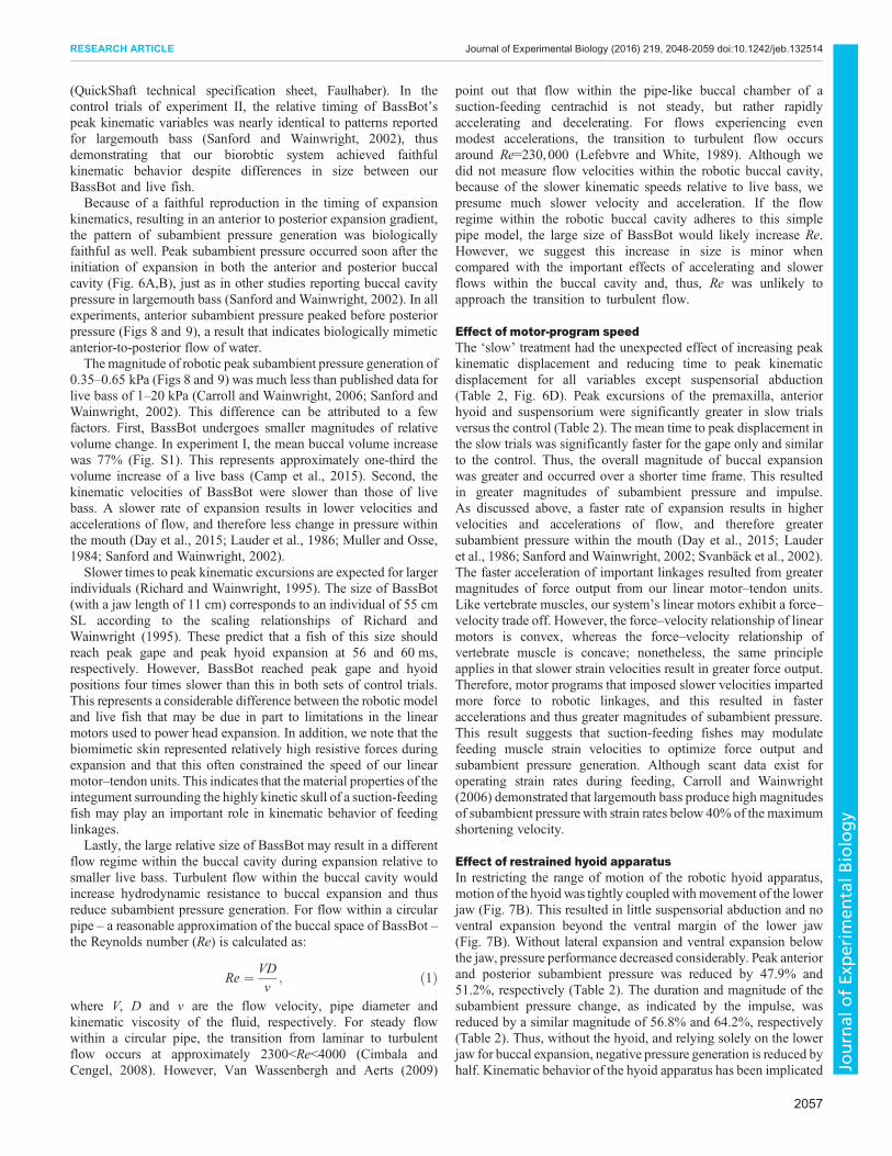
Fig. 3. Bioroboticmodel of the suction-feeding systemofthe largemouth bass (M. salmoides). (A) Lateral view ofthe robotic cranium mounted to an aluminium axial skeleton(as) and pectoral girdle (p1) with biomimetic skin coveringhard skeletal elements cut from PMMA thermoplastic.Anterior and posterior canulae (ac and pc, respectively) passinto the oral cavity and accept two catheter-tipped pressuretransducers. (B) Ventral view of the lower jaw (lj) and hyoidand branchial apparatus, including hyoid bars (hb); basihyal(bh), urohyal-basibranchial unit (ub) and hypobranchial(hbr); a Teflon-coated wire tendon passes through theposterior urohyal and is attached to a pair of linear motorsrepresenting the sternohyoideus-hypaxial muscle complex(sh). The protractor hyoideus (ph) is represented by a latexband anchored to the lower jaw near the mandibularsymphysis and to the anterior hyoid bars. (C) Lateral view ofthe dorsal maxillary apparatus composed of the premaxilla(pm) and maxilla (mx) pivoting about the robotic nasal bone(ns) via a ball joint. (D) Lateral view of the roboticposterolateral neurocranium (nr) about which the dorsalsuspensorium (ss) abducts; the dorsal opercular apparatus(op) articulates with the suspensorium at a ball joint,permitting rotation in the sagittal plane driven by a motor andwire–tendon unit representing the levator operculi (lo).(E) Lateral view of the mandibular-maxillary articulation,quadrato-articular joint, ventral opercular apparatus andhyoid apparatus. A wire–tendon unit inserting along theposteromedial face of the lower jawand originating at a linearmotor represents the adductor mandibulae (am) musclesthat adduct the lower jaw.
2051
RESEARCH ARTICLE Journal of Experimental Biology (2016) 219, 2048-2059 doi:10.1242/jeb.132514
Journal
ofEx
perim
entalB
iology

dorsoposterior flange meant to represent the articulating surfaces ofthe pterotic and sphenotic bones (Fig. 3D). The maxilla articulateswith the lower jaw via a socket-head bolt (Fig. 3B,E) and with theneurocranium via a swivel-ball joint representing the articulatingsurface of the nasal (Fig. 3C), thus permitting anterior–posteriorrotation and lateral abduction. Motion along the mandibular-maxillary articulation is constrained by a bolt in a C-shaped groovewithin the ventral heads of the maxilla and premaxilla (Fig. 3E). Thehyoid apparatus rotates ventrally about 12.7 mm low-densitypolyethylene (LDPE) spacers that represent the interhyals(Fig. 3B,E). The LDPE interhyals are fixed to the suspensoriumby a bolt and articulate with a ball joint of a 59 mm turnbuckle(model RVXL/SLH, Traxxas, Plano, TX, USA) that represents thebones of the hyoid bar (i.e. epihyal, ceratohyal and hypohyal). Attheir anterior ends, the ball joints of the two hyoid bars articulatewith a PMMA basihyal (Fig. 3B,E). In addition to permitting ventralrotation, ball joints at either end of the hyoid bar turnbuckle permit
lateral abduction of the posterior head of the bars and, through theirfixed interhyal linkages, lateral abduction of the suspensoria. Theentire robotic head is fixed to an aluminium spine (Fig. 3A).
The basihyal articulates with a PMMA urohyal-basibranchial unitvia two halves of a Super Flex hinge (Fig. 3B). The urohyal-basibranchial unit articulates with a triangular unit representing thehypobranchials of the gill arches via one half of a Super Flex hinge(Fig. 3B,C). The PMMA hypobranchial unit articulates with asquare-shaped PMMA ceratobranchial unit, in which are cut twoopen hemispheres (Fig. 4). This ceratobranchial unit articulateswith a PMMA epibranchial that has a single hemisphere cutwithin it (Fig. 4). Both the hypobranchial-ceratobranchial andceratobranchial-epibranchial articulations are secured withwaterproof Fix-It Tape (Top Tape & Label, Wheatfield, NY,USA). Each open hemisphere is covered on its posterior face with avalve cut from 0.102 mm tan polyester shim stock, thus restrictingthe posterior to anterior flow of water into the buccal cavity during
BA eb
hb
cv
ev
cb
cb
hb
cv
eveb
Fig. 4. Schematic representation of the branchialapparatus of a biorobotic model of the suction-feedingsystem of the largemouth bass (M. salmoides). Posteriorview (A) and schematic diagram (B) of the PMMAthermoplastic hypobranchial (hb), ceratobranchial (cb) andepibranchial (eb) units. The open areas in the ceratobranchial(cb) and epibranchial (eb) units are covered on their posteriorfaces by a ceratobranchial (cv) and epibranchial valve (ev),respectively.
0
0.25
0.50
0.75
0
0.2
0.4
0.6
0.8
0
0.2
0.4
0.6
0 10 20 30 40 50 0 20 40 60
0 25 50 75Time (ms)
Dis
plac
emen
t (cm
)
GapePremaxilla
Anterior hyoidPosterior hyoidSuspensorium
GapePremaxilla
Anterior hyoidPosterior hyoidSuspensorium
GapePremaxilla
Anterior hyoidPosterior hyoidSuspensorium
Bass 1
Bass 2
Bass 3
50 75 100
GapePremaxillaAnterior hyoidPosterior hyoidSuspensorium
DC
A B
Dis
plac
emen
t (cm
)
Fig. 5. Plots of kinematic variables during feeding in live largemouth bass. (A–C) Kinematic profiles of buccal expansion during feeding in each of the threebass specimens studied (bass 1–3, respectively). (D) Bar plot of time to peak displacement for each kinematic variable for each of the three bass specimens.N=5feeding events. Data points and whiskers in plots represent the mean±1 s.e.m.
2052
RESEARCH ARTICLE Journal of Experimental Biology (2016) 219, 2048-2059 doi:10.1242/jeb.132514
Journal
ofEx
perim
entalB
iology

expansion (Fig. 4). The epibranchial unit is fixed to the posteriorface of a hemispherical tube that forms the roof of the buccal cavity(Fig. 3). This effectively isolates the buccal cavity and followsLauder (1983), who found that pressure changes in the opercularcavity did not alter pressure in the buccal cavity during suctionfeeding. Furthermore, because the buccal cavity is isolated and itshydrodynamics are independent of an opercular cavity, we did notinclude a functional opercular chamber in our model.Five Quickshaft linear DC servomotors (model LM 2070-80-1,
Faulhaber, Schönaich, Germany) are integrated as the muscularactuation. Two linear motors function as the adductor mandibulaecomplex (AM), two as the sternohyoideus-hypaxial musculature(SA) and one as the levator operculi (LO).Motors are affixed to theirinsertion points via tendons consisting of 0.5 mm diameter Teflon-coated stainless-steel wire passed through flexible cable housing.Tendon geometry is based on data recorded from dissections ofpreserved specimens and µCT analysis. The AMmotor tendons pass
through a nylon control-horn bracket (model DUB559, Du Bro RC,Wauconda, IL, USA) on the medial faces of the PMMA suspensoriaand insert on the medial face of the mandible. The LO motortendons emerge from control-horn brackets on the posterodorsalaspect of the PMMA neurocranium and insert on to the dorsal edgeof the PMMA opercular unit. The SAM motor tendons originatefrom an aluminium pectoral girdle (Fig. 3A) and insert on theventral aspect of the urohyal (Fig. 2B). Speed and position of eachmechanical unit is programmable with a customized AdvancedSerial Write and Read virtual instrument in LabView (NationalInstruments, Austin, TX, USA).
The entire head of the robotic model is enveloped in ultrathin,150 µm thick, natural rubber latex to represent the skin (Fig. 3A).This skin analog is attached in two symmetrical pieces to thePMMA skeleton by waterproof Fix-It Tape. These two contralateralpieces are joined at a seam oriented along the ventral midline of therobotic jaw and hyoid apparatus, and adhere posteriorly to the lateral
0
1
2
3
0 100 200 300 400 500 0 100 200 300 400 500Time (ms)
Dis
plac
emen
t (cm
)
GapePremaxillaAnterior hyoidPosterior hyoidSuspensorium
Anterior pressurePosterior pressure
C
lj
pm
ahph
or
qu
or
qu
A B
D
Gape
Premaxilla
Anterior hyoid
Posterior hyoid
Suspensorium
Gape
Premaxilla
Anterior hyoid
Posterior hyoid
Suspensorium
200 300 400 500 600 700Time (ms)
Control
Slow
–0.6
–0.4
–0.2
0
Pre
ssur
e (k
Pa)
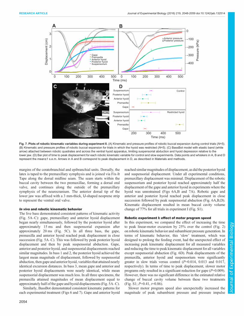
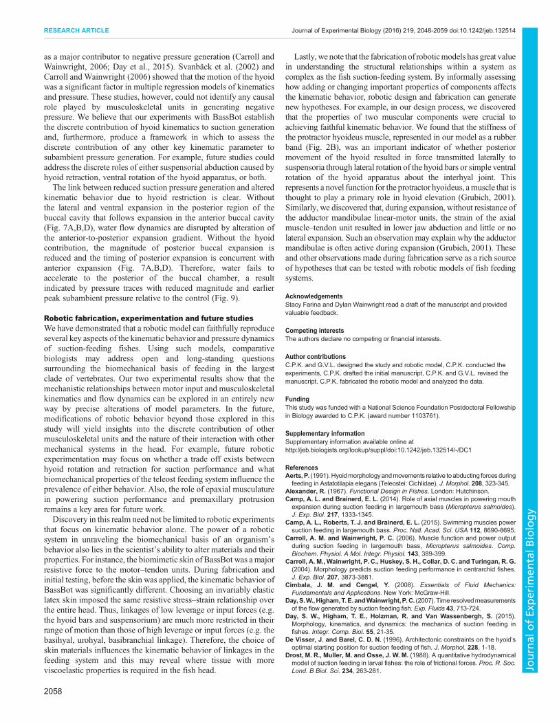
Fig. 6. Plots of robotic kinematic variables during experiment I. (A) Kinematic and pressure profiles of robotic buccal expansion during ‘control’ trials(N=5). (B) Kinematic and pressure profiles of robotic buccal expansion for trials in which the velocity of the three linear motor units was decreased 25% relative tocontrol trials (i.e. ‘slow’ trials, N=5). (C) BassBot model showing the position of points recorded for kinematic variables: anteroventral tip of the lower jaw (lj),anterior-most point of the premaxilla (pm), ventral orbit (or), ventral margin of the robotic quadrate (qu), anterior hyoid (ah) and posterior hyoid (ph). (D) Bar plot oftime to peak displacement for each robotic kinematic variable for control and slow experiments. Data points and whiskers in A, B and D represent the mean±1s.e.m. Arrows in A and B correspond to peak displacement as described in Materials and methods.
Table 1. Pressure variable comparison for robotic experiment I in which time to peak motor excursion was increased 25%
Time to peak (ms) Peak pressure (Pa) Impulse (N s)
Anterior Posterior Anterior Posterior Anterior Posterior
Control 95.8±4.4 101.8±5.1 −442.9±4.5 −405.9±31.5 44.1±26.1 44.1±6.2Slow 87.8±0.6 95.4±0.4 −639.2±1.2 −618.7±15.5 63.0±22.0 86.3±1.9Change −80.0 −6.4 −196.3 −212.8 18.9 42.2t 1.82 1.25 5.59 6.24 4.07 6.53P 0.14 0.279 0.002 <0.001 0.012 0.002
Data for control and slow trials are means±s.e.m. Variable means were compared with a two-sample Student’s t-test.
2053
RESEARCH ARTICLE Journal of Experimental Biology (2016) 219, 2048-2059 doi:10.1242/jeb.132514
Journal
ofEx
perim
entalB
iology
margins of the ceratobranchial and epibranchial units. Dorsally, thelatex is taped to the premaxillary symphysis and is joined via Fix-ItTape along the dorsal midline seam. The seam starts within thebuccal cavity between the two premaxillae, forming a dorsal oralvalve, and continues along the outside of the premaxillarysymphysis of the neurocranium. The anterior dorsal tip of thelower jaw was affixed with a 3 mm-thick, U-shaped neoprene stripto represent the ventral oral valve.
In vivo and robotic kinematic behaviorThe live bass demonstrated consistent patterns of kinematic activity(Fig. 5A–C): gape, premaxillary and anterior hyoid displacementbegan nearly simultaneously, followed by the posterior hyoid afterapproximately 15 ms and then suspensorial expansion afterapproximately 20 ms (Fig. 5C). In all three bass, the gape,premaxilla and anterior hyoid reached peak displacement in closesuccession (Fig. 5A–C). This was followed by peak posterior hyoiddisplacement and then by peak suspensorial abduction. Gape,anterior and posterior hyoid, and suspensorial displacements reachedsimilar magnitudes. In bass 1 and 2, the posterior hyoid achieved thelargest mean magnitude of displacement, followed by suspensorialabduction, then gape and anterior hyoid, variables that attained nearlyidentical excursion distances. In bass 3, mean gape and anterior andposterior hyoid displacements were nearly identical, while meansuspensorial displacement was much less. In all three specimens, thepremaxilla attained magnitudes of mean displacement equal toapproximately half of the gape and hyoid displacements (Fig. 5A–C).Similarly, BassBot demonstrated consistent kinematic patterns for
each experimental treatment (Figs 6 and 7). Gape and anterior hyoid
reached similarmagnitudes of displacement, as did the posterior hyoidand suspensorial displacement. Under all experimental conditions,premaxillary displacement was minimal. Displacement of the roboticsuspensorium and posterior hyoid reached approximately half thedisplacement of the gape and anterior hyoid in experiments where thehyoid was unrestrained (Figs 6A,B and 7A). Robotic gape andanterior and posterior hyoid reached peak displacement in closesuccession followed by peak suspensorial abduction (Fig. 6A,B,D).Kinematic displacement resulted in mean buccal cavity volumechange of 77% for all trials in experiment I (Fig. S1).
Robotic experiment I: effect of motor program speedIn this experiment, we compared the effect of increasing the timeto peak linear-motor excursion by 25% over the control (Fig. 2)on robotic kinematic behavior and subambient pressure generation. Interms of kinematic behavior, this ‘slow’ treatment, which wasdesigned to prolong the feeding event, had the unexpected effect ofincreasing peak kinematic displacement for all measured variablesand reducing the time to peak kinematic displacement for all variablesexcept suspensorial abduction (Fig. 6D). Peak displacements of thepremaxilla, anterior hyoid and suspensorium were significantlygreater in slow trials versus control (P=0.014, 0.013 and 0.017,respectively). In terms of time to peak displacement, slower motorprograms only resulted in a significant reduction for gape (P=0.009).However, there was no significant difference in the estimated relativechange of buccal cavity volume between these two treatments(Fig. S1; P=0.41, t=0.86).
Slower motor program speed also unexpectedly increased themagnitude of peak subambient pressure and pressure impulse
0
1
2
3
0 100 200 300 400 500 0 100 200 300 400 500Time (ms)
Dis
plac
emen
t (cm
)
200 300 400 500Time (ms)
C
A B
D
Gape
Premaxilla
Anterior hyoid
Posterior hyoid
Suspensorium
Gape
Premaxilla
Anterior hyoid
Posterior hyoid
Suspensorium
Control
Restricted hyoid
GapePremaxillaAnterior hyoidPosterior hyoidSuspensorium –400
–300
–200
–100
0
Pre
ssur
e (k
Pa)
Anterior pressurePosterior pressure
Fig. 7. Plots of robotic kinematic variables during experiment II. (A) Kinematic and pressure profiles of robotic buccal expansion during control trials (N=5).(B) Kinematic and pressure profiles of robotic buccal expansion for trials in which the hyoid was restricted (N=5). (C) BassBot model with elastic band (whitearrow) attached between robotic quadrates and across the ventral hyoid apparatus, limiting suspensorial abduction and hyoid depression relative to thelower jaw. (D) Bar plot of time to peak displacement for each robotic kinematic variable for control and slow experiments. Data points and whiskers in A, B and Drepresent the mean±1 s.e.m. Arrows in A and B correspond to peak displacement in D, as described in Materials and methods.
2054
RESEARCH ARTICLE Journal of Experimental Biology (2016) 219, 2048-2059 doi:10.1242/jeb.132514
Journal
ofEx
perim
entalB
iology

(Figs 6A,B, 8). Time to peak subambient pressure did not changesignificantly in both the anterior and posterior buccal cavity(P=0.14 and 0.279; Table 1). With slower motor speed, anterior andposterior magnitudes of peak subambient pressure increasedsignificantly (P =0.002 and <0.001, respectively; Table 1). A25% increase in time to peak motor excursion resulted in asignificant increase in anterior and posterior impulse.
Robotic experiment II: effect of restrained hyoid apparatusIn experiment II, we compared the effect of restricting hyoidmovement on kinematic behavior and subambient pressuregeneration. Under these conditions, hyoid retraction was
permitted; however, hyoid rotation relative to the lower jaw andlateral expansion and abduction of the suspensoria were limited. Asintended, restriction of the hyoid significantly limited peakdisplacement of the anterior and posterior hyoid and abduction ofthe suspensoria (all P<0.001). Peak displacement of the anterior andposterior hyoid was reduced by 0.94 cm (37%) and 0.77 cm (46%),respectively, while peak displacement of the suspensoria wasreduced by 1.78 cm (93%). In contrast, restriction of the hyoidincreased the peak displacement of the gape 0.52 cm (24%) andpremaxilla 0.04 cm (44%); however, only the change in gape wassignificant (P=0.026). Time to peak displacement was unchangedfor the anterior and posterior hyoid and suspensorium (P=0.846,
Anterior Posterior
–600
–400
–200
0
0 100 200 300 400 5000 100 200 300 400 500
Pre
ssur
e (P
a)
ControlSlow
Time (ms)
Control Slow Control Slow
Pea
k pr
essu
re (P
a)
405060708090
−600
−500
−400
Impu
lse
(N s
)
Fig. 8. Negative pressure-generation performance resulting fromchanges in linear motor program speed during suction feeding. In trials6–10 (slow), velocity for all three motor programs was decreased by 25%relative to trials 1–5 (control). Solid circles in the upper panel represent meanvalues; ±1 s.e.m. is shown in a lighter color for each curve. Solid circles in thelower panel represent the change in mean peak subambient pressure andimpulse between the control and slow experiments (±1 s.e.m.).
Table 2. Pressure variable comparison for robotic experiment II in which movement of the hyoid apparatus was restricted
Time to peak (ms) Peak pressure (Pa) Impulse (N s)
Anterior Posterior Anterior Posterior Anterior Posterior
Control 163.8±5.5 181.4±3.3 −380.9±1.8 −453.3±14.5 59.9±9.6 55.7±0.8Restricted hyoid 134.2±1.2 145.6±1 −198.3±1.3 −221.2±3.7 25.9±5.6 19.9±0.6Change −29.6 −35.8 182.5 232.2 −34.0 −35.8t 5.22 10.24 −12.22 −20.99 −15.52 −35.1P 0.005 <0.001 <0.001 <0.001 <0.001 <0.001
Data for control and slow trials are means±s.e.m. Variable means were compared with a two-sample Student’s t-test.
Control Restrictedhyoid
Control Restrictedhyoid
Anterior Posterior
−400
−300
−200
−100
0
0 100 200 300 400 500 0 100 200 300 400 500Time ( ms)
Pre
ssur
e (P
a)
ControlRestrictedhyoid
Pea
k pr
essu
re (P
a)Im
puls
e (N
s)
20
30
40
50
60
−400
−300
−200
Fig. 9. The effect of restricted hyoid movement on robotic negativepressure generation performance during suction feeding. Solid circles inthe upper panel represent the represent mean values; ±1 s.e.m. is shown in alighter color for each curve. Solid circles in the lower panel represent thechange in mean peak subambient pressure and impulse when movement ofthe robotic hyoid was restricted (±1 s.e.m.).
2055
RESEARCH ARTICLE Journal of Experimental Biology (2016) 219, 2048-2059 doi:10.1242/jeb.132514
Journal
ofEx
perim
entalB
iology
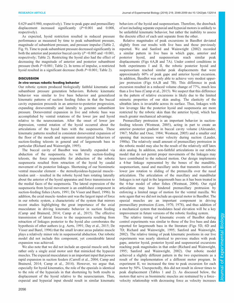
0.629 and 0.980, respectively). Time to peak gape and premaxillarydisplacement increased significantly (P=0.001 and 0.008,respectively).As expected, hyoid restriction resulted in reduced pressure
performance as measured by time to peak subambient pressure,magnitude of subambient pressure, and pressure impulse (Table 2,Fig. 9). Time to peak subambient pressure decreased significantly inboth the anterior and posterior buccal cavity (P =0.005 and <0.001,respectively; Table 2). Restricting the hyoid also had the effect ofdecreasing the magnitude of anterior and posterior subambientpressure (both P<0.001; Table 2). In terms of impulse, a restrictedhyoid resulted in a significant decrease (both P<0.001; Table 2).
DISCUSSIONIn vivo versus robotic feeding behaviorOur robotic system produced biologically faithful kinematic andsubambient pressure generation behaviors. Robotic kinematicbehavior was similar to live bass behavior and generalizedkinematic patterns of suction feeding fishes in that the buccalcavity expansion proceeds in an anterior-to-posterior progression,expanding dorsoventrally and laterally to generate subambientpressure. Dorsoventral expansion in live and robotic bass wasaccomplished by ventral rotations of the lower jaw and hyoidrelative to the neurocranium. After the onset of lower jawdepression, ventral rotation of the hyoid occurred about thearticulations of the hyoid bars with the suspensoria. Thesekinematic patterns resulted in consistent dorsoventral expansion ofthe floor of the mouth and represent stereotypical behaviors ofsuction-feeding teleosts in general and of largemouth bass inparticular (Richard and Wainwright, 1995).The buccal cavity of BassBot was laterally expanded via
abduction of the suspensoria. As with live suction-feedingteleosts, the force responsible for abduction of the roboticsuspensoria resulted from retraction of the hyoid by caudalmovement of its posterior linkages. Shortening of our biomimeticventral muscular element – the sternohyoideus-hypaxial muscle–tendon unit – resulted in the robotic hyoid bars rotating laterallyabout the anterior of the hyoid apparatus and force transmission tothe medial faces of the suspensoria. The lateral expression of thesuspensoria from hyoid movement is an established component insuction-feeding fishes (Aerts, 1991; De Visser and Barel, 1996). Inaddition, the axial muscle–tendon unit was the largest input of forcein our robotic system, a characteristic of the system that mirrorsrecent studies highlighting the great importance of the axialmusculature in driving kinematic behavior in suction feeding(Camp and Brainerd, 2014; Camp et al., 2015). The effectivetransmission of lateral forces to the suspensoria resulting fromretraction of linkages posterior to the hyoid also corroborates thehypothesis of other authors (e.g. Aerts, 1991; Day et al., 2015; DeVisser and Barel, 1996) that the small levator arcus palatini muscleplays a relatively minor role in suspensorial abduction. Our roboticmodel did not include this component, yet considerable lateralexpansion was achieved.We also note that we did not include an epaxial muscle unit, but
rather only a single axial motor unit that mimicked the hypaxialmuscles. The expaxial musculature is an important input that powersrapid expansion in suction feeders (Carroll et al., 2004; Camp andBrainerd, 2014; Camp et al., 2014). However, we argue that,especially for hyoid kinematics, the role of the epaxials is identicalto the role of the hypaxials in that shortening by both results indisplacement of the hyoid relative to the neurocranium. Thus,expaxial and hypaxial input should result in similar kinematic
behaviors of the hyoid and suspensorium. Therefore, the drawbackof not including separate expaxial and hypaxial motors is unlikely tobe unfaithful kinematic behavior, but rather the inability to assessthe discrete effect of each unit separate from the other.
Relative magnitudes of peak excursions in BassBot deviatedslightly from our results with live bass and those previouslyreported. We and Sanford and Wainwright (2002) recordeda similar pattern in live bass in which gape, anterior andposterior hyoid, and suspensorium reach similar peakdisplacements (Figs 6A,B and 7A). Under control conditions inboth experiments I and II, the robotic posterior hyoid andsuspensorium reached similar peak displacements that wereapproximately 60% of peak gape and anterior hyoid excursion.In addition, BassBot was only able to achieve very modest upper-jaw protrusion (Figs 6A,B and 7B). This difference in peakexcursion resulted in a reduced volume change of 77%, much lessthan a live bass (Camp et al., 2015). We suspect that this differencein the pattern of relative excursions is likely due to the limitedmimetic properties of our skin analog. The elasticity of theultrathin latex is invariable across its surface. Thus, linkages withlow leverage like the posterior hyoid and suspensoria are morerestricted by the robotic skin than the anterior hyoid, which hasmuch greater mechanical advantage.
Premaxillary protrusion is an important behavior in suction-feeding teleosts (Westneat, 2005), acting in part to create ananterior–posterior gradient in buccal cavity volume (Alexander,1967; Muller and Osse, 1984; Westneat, 2005) and a smaller oralopening that increases water velocity during suction (Lauder,1980a). The relatively small amount of premaxillary protrusion inthe robotic model may also be the result of the relatively stiff latexskin analog. In addition, non-faithful articulations in our roboticmodel that do not permit proper movements of the linkages mayhave contributed to the reduced motion. Our design implementsa 4-bar linkage represented by the bones of the mandible,suspensorium, nasal and maxillary units that transmits motion oflower jaw rotation to sliding of the premaxilla over the nasalarticulation. The articulation of the maxillary and mandibularlinkages is not rigid in the largemouth bass as it has been treated inthe 4-bar model of other fishes (Westneat, 2004). Our rigidarticulation may have hindered premaxillary protrusion byenforcing a limited range of motion for the ventral maxilla. Wenote again that we did not include an epaxial motor in BassBot. Theepaxial muscles are an important component in drivingpremaxillary protrusion (Liem, 1970, 1978), and thus addition ofa mechanical system that modulates head elevation will be a keyimprovement in future versions of the robotic feeding system.
The relative timing of kinematic events of BassBot duringcontrol experiments was similar to those of the live bass and datareported for largemouth bass in the literature (Figs 5D, 6D and7D; Richard and Wainwright, 1995; Sanford and Wainwright,2002). The relative timing of peak kinematic positions in our liveexperiments was nearly identical to previous studies with peakgape, anterior hyoid, posterior hyoid and suspensorial excursionsreaching peak magnitudes in that order (Richard and Wainwright,1995; Sanford and Wainwright, 2002). Our robotic modelachieved a slightly different pattern in the two experiments as aresult of the implementation of a different motor program. Inexperiment II, we increased the time to peak excursion for eachmotor by 50%. Unexpectedly, this did not result in slower times topeak displacement (Tables 1 and 2). As discussed below, themotors that serve as biomimetic muscles are restrained by a force–velocity relationship with decreasing force as velocity increases
2056
RESEARCH ARTICLE Journal of Experimental Biology (2016) 219, 2048-2059 doi:10.1242/jeb.132514
Journal
ofEx
perim
entalB
iology
(QuickShaft technical specification sheet, Faulhaber). In thecontrol trials of experiment II, the relative timing of BassBot’speak kinematic variables was nearly identical to patterns reportedfor largemouth bass (Sanford and Wainwright, 2002), thusdemonstrating that our biorobtic system achieved faithfulkinematic behavior despite differences in size between ourBassBot and live fish.Because of a faithful reproduction in the timing of expansion
kinematics, resulting in an anterior to posterior expansion gradient,the pattern of subambient pressure generation was biologicallyfaithful as well. Peak subambient pressure occurred soon after theinitiation of expansion in both the anterior and posterior buccalcavity (Fig. 6A,B), just as in other studies reporting buccal cavitypressure in largemouth bass (Sanford and Wainwright, 2002). In allexperiments, anterior subambient pressure peaked before posteriorpressure (Figs 8 and 9), a result that indicates biologically mimeticanterior-to-posterior flow of water.The magnitude of robotic peak subambient pressure generation of
0.35–0.65 kPa (Figs 8 and 9) was much less than published data forlive bass of 1–20 kPa (Carroll and Wainwright, 2006; Sanford andWainwright, 2002). This difference can be attributed to a fewfactors. First, BassBot undergoes smaller magnitudes of relativevolume change. In experiment I, the mean buccal volume increasewas 77% (Fig. S1). This represents approximately one-third thevolume increase of a live bass (Camp et al., 2015). Second, thekinematic velocities of BassBot were slower than those of livebass. A slower rate of expansion results in lower velocities andaccelerations of flow, and therefore less change in pressure withinthe mouth (Day et al., 2015; Lauder et al., 1986; Muller and Osse,1984; Sanford and Wainwright, 2002).Slower times to peak kinematic excursions are expected for larger
individuals (Richard and Wainwright, 1995). The size of BassBot(with a jaw length of 11 cm) corresponds to an individual of 55 cmSL according to the scaling relationships of Richard andWainwright (1995). These predict that a fish of this size shouldreach peak gape and peak hyoid expansion at 56 and 60 ms,respectively. However, BassBot reached peak gape and hyoidpositions four times slower than this in both sets of control trials.This represents a considerable difference between the robotic modeland live fish that may be due in part to limitations in the linearmotors used to power head expansion. In addition, we note that thebiomimetic skin represented relatively high resistive forces duringexpansion and that this often constrained the speed of our linearmotor–tendon units. This indicates that the material properties of theintegument surrounding the highly kinetic skull of a suction-feedingfish may play an important role in kinematic behavior of feedinglinkages.Lastly, the large relative size of BassBot may result in a different
flow regime within the buccal cavity during expansion relative tosmaller live bass. Turbulent flow within the buccal cavity wouldincrease hydrodynamic resistance to buccal expansion and thusreduce subambient pressure generation. For flow within a circularpipe – a reasonable approximation of the buccal space of BassBot –the Reynolds number (Re) is calculated as:
Re ¼ VD
v; ð1Þ
where V, D and v are the flow velocity, pipe diameter andkinematic viscosity of the fluid, respectively. For steady flowwithin a circular pipe, the transition from laminar to turbulentflow occurs at approximately 2300<Re<4000 (Cimbala andCengel, 2008). However, Van Wassenbergh and Aerts (2009)
point out that flow within the pipe-like buccal chamber of asuction-feeding centrachid is not steady, but rather rapidlyaccelerating and decelerating. For flows experiencing evenmodest accelerations, the transition to turbulent flow occursaround Re=230,000 (Lefebvre and White, 1989). Although wedid not measure flow velocities within the robotic buccal cavity,because of the slower kinematic speeds relative to live bass, wepresume much slower velocity and acceleration. If the flowregime within the robotic buccal cavity adheres to this simplepipe model, the large size of BassBot would likely increase Re.However, we suggest this increase in size is minor whencompared with the important effects of accelerating and slowerflows within the buccal cavity and, thus, Re was unlikely toapproach the transition to turbulent flow.
Effect of motor-program speedThe ‘slow’ treatment had the unexpected effect of increasing peakkinematic displacement and reducing time to peak kinematicdisplacement for all variables except suspensorial abduction(Table 2, Fig. 6D). Peak excursions of the premaxilla, anteriorhyoid and suspensorium were significantly greater in slow trialsversus the control (Table 2). The mean time to peak displacement inthe slow trials was significantly faster for the gape only and similarto the control. Thus, the overall magnitude of buccal expansionwas greater and occurred over a shorter time frame. This resultedin greater magnitudes of subambient pressure and impulse.As discussed above, a faster rate of expansion results in highervelocities and accelerations of flow, and therefore greatersubambient pressure within the mouth (Day et al., 2015; Lauderet al., 1986; Sanford and Wainwright, 2002; Svanbäck et al., 2002).The faster acceleration of important linkages resulted from greatermagnitudes of force output from our linear motor–tendon units.Like vertebrate muscles, our system’s linear motors exhibit a force–velocity trade off. However, the force–velocity relationship of linearmotors is convex, whereas the force–velocity relationship ofvertebrate muscle is concave; nonetheless, the same principleapplies in that slower strain velocities result in greater force output.Therefore, motor programs that imposed slower velocities impartedmore force to robotic linkages, and this resulted in fasteraccelerations and thus greater magnitudes of subambient pressure.This result suggests that suction-feeding fishes may modulatefeeding muscle strain velocities to optimize force output andsubambient pressure generation. Although scant data exist foroperating strain rates during feeding, Carroll and Wainwright(2006) demonstrated that largemouth bass produce high magnitudesof subambient pressure with strain rates below 40% of the maximumshortening velocity.
Effect of restrained hyoid apparatusIn restricting the range of motion of the robotic hyoid apparatus,motion of the hyoid was tightly coupled with movement of the lowerjaw (Fig. 7B). This resulted in little suspensorial abduction and noventral expansion beyond the ventral margin of the lower jaw(Fig. 7B). Without lateral expansion and ventral expansion belowthe jaw, pressure performance decreased considerably. Peak anteriorand posterior subambient pressure was reduced by 47.9% and51.2%, respectively (Table 2). The duration and magnitude of thesubambient pressure change, as indicated by the impulse, wasreduced by a similar magnitude of 56.8% and 64.2%, respectively(Table 2). Thus, without the hyoid, and relying solely on the lowerjaw for buccal expansion, negative pressure generation is reduced byhalf. Kinematic behavior of the hyoid apparatus has been implicated
2057
RESEARCH ARTICLE Journal of Experimental Biology (2016) 219, 2048-2059 doi:10.1242/jeb.132514
Journal
ofEx
perim
entalB
iology
as a major contributor to negative pressure generation (Carroll andWainwright, 2006; Day et al., 2015). Svanbäck et al. (2002) andCarroll and Wainwright (2006) showed that the motion of the hyoidwas a significant factor in multiple regression models of kinematicsand pressure. These studies, however, could not identify any causalrole played by musculoskeletal units in generating negativepressure. We believe that our experiments with BassBot establishthe discrete contribution of hyoid kinematics to suction generationand, furthermore, produce a framework in which to assess thediscrete contribution of any other key kinematic parameter tosubambient pressure generation. For example, future studies couldaddress the discrete roles of either suspensorial abduction caused byhyoid retraction, ventral rotation of the hyoid apparatus, or both.The link between reduced suction pressure generation and altered
kinematic behavior due to hyoid restriction is clear. Withoutthe lateral and ventral expansion in the posterior region of thebuccal cavity that follows expansion in the anterior buccal cavity(Fig. 7A,B,D), water flow dynamics are disrupted by alteration ofthe anterior-to-posterior expansion gradient. Without the hyoidcontribution, the magnitude of posterior buccal expansion isreduced and the timing of posterior expansion is concurrent withanterior expansion (Fig. 7A,B,D). Therefore, water fails toaccelerate to the posterior of the buccal chamber, a resultindicated by pressure traces with reduced magnitude and earlierpeak subambient pressure relative to the control (Fig. 9).
Robotic fabrication, experimentation and future studiesWe have demonstrated that a robotic model can faithfully reproduceseveral key aspects of the kinematic behavior and pressure dynamicsof suction-feeding fishes. Using such models, comparativebiologists may address open and long-standing questionssurrounding the biomechanical basis of feeding in the largestclade of vertebrates. Our two experimental results show that themechanistic relationships between motor input and musculoskeletalkinematics and flow dynamics can be explored in an entirely newway by precise alterations of model parameters. In the future,modifications of robotic behavior beyond those explored in thisstudy will yield insights into the discrete contribution of othermusculoskeletal units and the nature of their interaction with othermechanical systems in the head. For example, future roboticexperimentation may focus on whether a trade off exists betweenhyoid rotation and retraction for suction performance and whatbiomechanical properties of the teleost feeding system influence theprevalence of either behavior. Also, the role of epaxial musculaturein powering suction performance and premaxillary protrusionremains a key area for future work.Discovery in this realm need not be limited to robotic experiments
that focus on kinematic behavior alone. The power of a roboticsystem in unraveling the biomechanical basis of an organism’sbehavior also lies in the scientist’s ability to alter materials and theirproperties. For instance, the biomimetic skin of BassBot was amajorresistive force to the motor–tendon units. During fabrication andinitial testing, before the skin was applied, the kinematic behavior ofBassBot was significantly different. Choosing an invariably elasticlatex skin imposed the same resistive stress–strain relationship overthe entire head. Thus, linkages of low leverage or input forces (e.g.the hyoid bars and suspensorium) are much more restricted in theirrange of motion than those of high leverage or input forces (e.g. thebasihyal, urohyal, basibranchial linkage). Therefore, the choice ofskin materials influences the kinematic behavior of linkages in thefeeding system and this may reveal where tissue with moreviscoelastic properties is required in the fish head.
Lastly,we note that the fabrication of roboticmodels has great valuein understanding the structural relationships within a system ascomplex as the fish suction-feeding system. By informally assessinghow adding or changing important properties of components affectsthe kinematic behavior, robotic design and fabrication can generatenew hypotheses. For example, in our design process, we discoveredthat the properties of two muscular components were crucial toachieving faithful kinematic behavior. We found that the stiffness ofthe protractor hyoideus muscle, represented in our model as a rubberband (Fig. 2B), was an important indicator of whether posteriormovement of the hyoid resulted in force transmitted laterally tosuspensoria through lateral rotation of the hyoid bars or simple ventralrotation of the hyoid apparatus about the interhyal joint. Thisrepresents a novel function for the protractor hyoideus, amuscle that isthought to play a primary role in hyoid elevation (Grubich, 2001).Similarly, we discovered that, during expansion, without resistance ofthe adductor mandibulae linear-motor units, the strain of the axialmuscle–tendon unit resulted in lower jaw abduction and little or nolateral expansion. Such an observation may explain why the adductormandibulae is often active during expansion (Grubich, 2001). Theseand other observations made during fabrication serve as a rich sourceof hypotheses that can be tested with robotic models of fish feedingsystems.
AcknowledgementsStacy Farina and Dylan Wainwright read a draft of the manuscript and providedvaluable feedback.
Competing interestsThe authors declare no competing or financial interests.
Author contributionsC.P.K. and G.V.L. designed the study and robotic model, C.P.K. conducted theexperiments, C.P.K. drafted the initial manuscript, C.P.K. and G.V.L. revised themanuscript. C.P.K. fabricated the robotic model and analyzed the data.
FundingThis study was funded with a National Science Foundation Postdoctoral Fellowshipin Biology awarded to C.P.K. (award number 1103761).
Supplementary informationSupplementary information available online athttp://jeb.biologists.org/lookup/suppl/doi:10.1242/jeb.132514/-/DC1
ReferencesAerts, P. (1991). Hyoidmorphologyandmovements relative toabducting forces during
feeding in Astatotilapia elegans (Teleostei: Cichlidae). J. Morphol. 208, 323-345.Alexander, R. (1967). Functional Design in Fishes. London: Hutchinson.Camp, A. L. and Brainerd, E. L. (2014). Role of axial muscles in powering mouth
expansion during suction feeding in largemouth bass (Micropterus salmoides).J. Exp. Biol. 217, 1333-1345.
Camp, A. L., Roberts, T. J. and Brainerd, E. L. (2015). Swimming muscles powersuction feeding in largemouth bass. Proc. Natl. Acad. Sci. USA 112, 8690-8695.
Carroll, A. M. and Wainwright, P. C. (2006). Muscle function and power outputduring suction feeding in largemouth bass, Micropterus salmoides. Comp.Biochem. Physiol. A Mol. Integr. Physiol. 143, 389-399.
Carroll, A. M., Wainwright, P. C., Huskey, S. H., Collar, D. C. and Turingan, R. G.(2004). Morphology predicts suction feeding performance in centrarchid fishes.J. Exp. Biol. 207, 3873-3881.
Cimbala, J. M. and Cengel, Y. (2008). Essentials of Fluid Mechanics:Fundamentals and Applications. New York: McGraw-Hill.
Day,S.W.,Higham,T.E.andWainwright,P.C. (2007).Time resolvedmeasurementsof the flow generated by suction feeding fish. Exp. Fluids 43, 713-724.
Day, S. W., Higham, T. E., Holzman, R. and Van Wassenbergh, S. (2015).Morphology, kinematics, and dynamics: the mechanics of suction feeding infishes. Integr. Comp. Biol. 55, 21-35.
De Visser, J. and Barel, C. D. N. (1996). Architectonic constraints on the hyoid’soptimal starting position for suction feeding of fish. J. Morphol. 228, 1-18.
Drost, M. R., Muller, M. and Osse, J. W. M. (1988). A quantitative hydrodynamicalmodel of suction feeding in larval fishes: the role of frictional forces. Proc. R. Soc.Lond. B Biol. Sci. 234, 263-281.
2058
RESEARCH ARTICLE Journal of Experimental Biology (2016) 219, 2048-2059 doi:10.1242/jeb.132514
Journal
ofEx
perim
entalB
iology

Esposito, C. J., Tangorra, J. L., Flammang, B. E. and Lauder, G. V. (2012). Arobotic fish caudal fin: effects of stiffness and motor program on locomotorperformance. J. Exp. Biol. 215, 56-67.
Ferry-Graham, L. A. and Lauder, G. V. (2001). Aquatic prey capture in ray-finnedfishes: a century of progress and new directions. J. Morphol. 248, 99-119.
Grubich, J. R. (2001). Prey capture in actinopterygian fishes: a review of suctionfeeding motor patterns with new evidence from an elopomorph fish, Megalopsatlanticus. Am. Zool. 41, 1258-1265.
Grubich, J. R. and Wainwright, P. C. (1997). Motor basis of suction feedingperformance in largemouth bass,Micropterus salmoides. J. Exp. Zool. 277, 1-13.
Hedrick, T. L. (2008). Software techniques for two- and three-dimensional kinematicmeasurements of biological and biomimetic systems. Bioinspir. Biomim. 3,034001.
Higham, T. E., Day, S. W. and Wainwright, P. C. (2006a). Multidimensionalanalysis of suction feeding performance in fishes: fluid speed, acceleration, strikeaccuracy and the ingested volume of water. J. Exp. Biol. 209, 2713-2725.
Higham, T. E., Day, S. W. andWainwright, P. C. (2006b). The pressures of suctionfeeding: the relation between buccal pressure and induced fluid speed incentrarchid fishes. J. Exp. Biol. 209, 3281-3287.
Holzman, R., Collar, D. C., Mehta, R. S. and Wainwright, P. C. (2012). Anintegrative modeling approach to elucidate suction-feeding performance. J. Exp.Biol. 215, 1-13.
Lauder, G. V. (1980a). Hydrodynamics of prey capture by teleost fishes. Biofluid.Mech. 2, 161-181.
Lauder, G. V. (1980b). The suction feeding mechanism in sunfishes (Lepomis): anexperimental analysis. J. Exp. Biol. 88, 49-72.
Lauder, G. V. (1983). Prey capture hydrodynamics in fishes: experimental tests oftwo models. J. Exp. Biol. 104, 1-13.
Lauder, G. V. (1985). Aquatic feeding in lower vertebrates. In Functional VertebrateMorphology (ed. M. Hildebrand, D. M. Bramble, K. F. Liem and D. B. Wake), pp.210-229. Cambridge: Harvard University Press.
Lauder, G. V. and Shaffer, H. B. (1985). Functional morphology of the feedingmechanism in aquatic ambystomatid salamanders. J. Morphol. 185, 297-326.
Lauder, G. V., Wainwright, P. C. and Findeis, E. (1986). Physiologicalmechanisms of aquatic prey capture in sunfishes: functional determinants ofbuccal pressure changes. Comp. Biochem. Physiol. A Physiol. 84, 729-734.
Lauder, G. V., Anderson, E. J., Tangorra, J. and Madden, P. G. A. (2007). Fishbiorobotics: kinematics and hydrodynamics of self-propulsion. J. Exp. Biol. 210,2767-2780.
Lauder, G. V., Lim, J., Shelton, R. andWitt, C. (2011). Robotic models for studyingundulatory locomotion in fishes. Mar. Tech. 45, 41-55.
Lefebvre, P. J. andWhite, F. M. (1989). Experiments on transition to turbulence in aconstant-acceleration pipe flow. J. Fluids Eng. 111, 428-432.
Liem, K. F. (1970). Comparative functional anatomy of the Nandidae (Pisces:Teleostei). Fieldiana Zool. 56, 1-166.
Liem, K. F. (1978). Modulatory multiplicity in the functional repertoire of the feedingmechanism in cichlid fishes. I. Piscivores. J. Morphol. 158, 323-360.
Meijering, E., Dzyubachyk, O. and Smal, I. (2012). Methods for cell and particletracking. Methods Enzymol. 504, 183-200.
Motta, P. J. and Wilga, C. D. (2000). Advances in the study of feeding behaviors,mechanisms, and mechanics of sharks. Environ. Biol. Fish. 20, 1-26.
Muller, M. and Osse, J. W. M. (1984). Hydrodynamics of suction feeding in fish.Trans. Zool. Soc. Lond. 37, 51-135.
Nauwelaerts, S., Wilga, C. D., Lauder, G. V. and Sanford, C. P. (2008). Fluiddynamics of feeding behaviour in white-spotted bamboo sharks. J. Exp. Biol. 211,3095-3102.
Nyberg, D. W. (1971). Prey capture in the largemouth bass. Am. Midl. Nat. 86,128-144.
Osse, J. W. and Muller, M. (1980). A model of suction feeding in teleostean fisheswith some implications for ventilation. In Environmental Physiology of Fishes(ed. M. A. Ali), pp. 335-352. New York: Plenum.
Richard, B. and Wainwright, P. (1995). Scaling the feeding mechanism oflargemouth bass (Micropterus salmoides): kinematics of prey capture. J. Exp.Biol. 198, 419-433.
Sanford, C. P. J. and Wainwright, P. C. (2002). Use of sonomicrometrydemonstrates the link between prey capture kinematics and suction pressure inlargemouth bass. J. Exp. Biol. 205, 3445-3457.
Svanback, R., Wainwright, P. C. and Ferry-Graham, L. A. (2002). Linking cranialkinematics, buccal pressure, and suction feeding performance in largemouthbass. Physiol. Biochem. Zool. 75, 532-543.
Van Wassenbergh, S. and Aerts, P. (2009). Aquatic suction feeding dynamics:insights from computational modelling. J. R. Soc. Interface 6, 149-158.
Wainwright, P. and Richard, B. (1995). Scaling the feeding mechanism of thelargemouth bass (Micropterus salmoides): motor pattern. J. Exp. Biol. 198,1161-1171.
Wainwright, P., Carroll, A. M., Collar, D. C., Day, S. W., Higham, T. E. andHolzman, R. A. (2007). Suction feeding mechanics, performance, and diversity infishes. Integr. Comp. Biol. 47, 96-106.
Westneat,M.W. (2004). Evolution of levers and linkages in the feedingmechanismsof fishes. Integr. Comp. Biol. 44, 378-389.
Westneat, M. W. (2005). Skull biomechanics and suction feeding in fishes. In FishBiomechanics (ed. R. E. Shadwick and G. V. Lauder), pp. 29-75. San Diego:Elsevier.
Wilga, C. D. and Sanford, C. P. (2008). Suction generation in white-spottedbamboo sharks Chiloscyllium plagiosum. J. Exp. Biol. 211, 3128-3138.
2059
RESEARCH ARTICLE Journal of Experimental Biology (2016) 219, 2048-2059 doi:10.1242/jeb.132514
Journal
ofEx
perim
entalB
iology