901 - ceragon - qinq cfg - pdf v1.5
DESCRIPTION
901 CERAGAONTRANSCRIPT

1
Ceragon Networks Ltd. (NASDAQ/TASE: CRNT) is a leading provider of highsolutions for cellular and fixed wireless operators, enterprises and government organizations. Ceragon’s FibeAirfamily offers scalable solutions for wireless transport of broadband services. Operating across multiple frequencies for IP and SONET/SDH protocols, FibeAir systems support the emerging needs of nextall-IP based services. Ceragon leads theefficient, robust connectivity required for LTE, WiMAX and converged networks.
Ceragon’s solutions are deployed by more than 150 service providers of all sizes, as well as in in nearly 100 countries. More information is available at www.ceragon.com
The Ceragon logo and FibeAir® are registered trademarks of Ceragon Networks Ltd. This brochure is being provided for informatcontained in this document, including product and feature specifications, are subject to change without notice. This brochureanyone a specific product or set of features related thereto.
www.ceragon.com
Q-in-Q Configuration
Ceragon Training Procedure
Ceragon Networks Ltd. (NASDAQ/TASE: CRNT) is a leading provider of high-capacity LTEsolutions for cellular and fixed wireless operators, enterprises and government organizations. Ceragon’s FibeAir
lutions for wireless transport of broadband services. Operating across multiple frequencies for IP and SONET/SDH protocols, FibeAir systems support the emerging needs of next-generation networks that are evolving to
IP based services. Ceragon leads the market in IP backhaul, offering a unique, native IP solution that provides the efficient, robust connectivity required for LTE, WiMAX and converged networks.
Ceragon’s solutions are deployed by more than 150 service providers of all sizes, as well as in hundreds of private networks, in nearly 100 countries. More information is available at www.ceragon.com
The Ceragon logo and FibeAir® are registered trademarks of Ceragon Networks Ltd. This brochure is being provided for informational purposes only. The contained in this document, including product and feature specifications, are subject to change without notice. This brochure shall not bind Ceragon to provide to anyone a specific product or set of features related thereto.
Q Configuration
v1.5
capacity LTE-ready wireless backhaul solutions for cellular and fixed wireless operators, enterprises and government organizations. Ceragon’s FibeAir® product
lutions for wireless transport of broadband services. Operating across multiple frequencies for IP generation networks that are evolving to
market in IP backhaul, offering a unique, native IP solution that provides the
hundreds of private networks,
ional purposes only. The details shall not bind Ceragon to provide to
2009
Q Configuration

2 Ceragon Training Procedure v1.5
Q-in-Q Configuration • Based on IP-10G IDU version 3.0.97, IP-10 IDU 2.8.25
1.0 Scope of paper
• Explain the process of configuring IP-10 to support Q-in-Q (S-VLAN + C-VLAN) using IP-10G EMS and N2X tester
2.0 Prerequisites
• Fully understand 802.1q protocol (including Q-in-Q, a.k.a VLAN Stacking)
• Be familiar with IP-10G basic configuration
• Be familiar with IP-10G switch configuration
• Be familiar with N2X configuration
3.0 Required Equipment
ITEM Quantity
IP-10 IDU 2
ODU 2
SMA RF COAX cables 1
30dB attenuators 2
IF cables (IDU-ODU) 2
Straight ETH cables 7
ETH switch 1
N2X (or other) Traffic Generator and Analyzer 1
PC with EMS 1

3 Ceragon Training Procedure v1.5
4.0 CLI settings for craft connection
• Baud - 115200
• Data bits - 8
• Parity – None
• Stop bits – 1
• Flow Control – None
• Username: admin
• Password: admin
5.0 README
1. It is recommended to refresh the EMS screen before reading and analyzing certain parameters.
2. Configuring preliminary actions are not explained in this paper. The engineer handling this procedure is assumed to have sufficient experience to handle such scenarios.
3. When test action requires transmission rate of 0 bps, reduce rate while setup is under
test. Do not stop the test to re-configure the streams.
6.0 Table of Contents
Step Description Page
7.0 Setup #1: Simple 802.1q (Managed Switch) 4
7.1 Setup Description 4
7.2 Setup Diagram 5
7.3 Setup Configuration 6
7.4 N2X Configuration 8
8.0 Setup #2: CN-PN-PN-CN (Metro Switch) 9
8.1 Setup Description 9
8.2 Setup Diagram 10
8.3 Setup Configuration 11
8.4 Actions and Results 13
8.5 N2X Results (screenshots) 14
9.0 Setup #3: CN-PN-PN-PN (Metro Switch) 15
9.1 Setup Description 15
9.2 Setup Diagram 16
9.3 Setup Configuration 17
9.4 N2X Configuration 18
9.5 Actions and Results 19
9.6 N2X Results (screenshots) 20

4 Ceragon Training Procedure v1.5
7.0 Setup #1: 802.1q (Managed Switch)
7.1 Setup Description
The purpose of this step is to verify that physical connections are properly set up.
The setup depicts a simple 802.1q configuration:
We transmit 2 tagged streams via GbE / FE ports (2&3) and receive the 2 streams through a single trunk on the other side of the radio link (port #2 of IDU-B).
Both IDUs are managed out of band by IP-10G EMS.
EMS PC is connected to the L2 switch.
(Diagram may not show properly when printed in B&W)
Port #2 as
Trunk (VID 10)
Radios as Trunk
Port #2 as
Trunk (VID 10,
VID 20)
Port #3 as
Trunk (VID 20)
IDU-B
IDU-A

5 Ceragon Training Procedure v1.5
7.2 Setup Diagram
Port 101/3: 2 streams -
Stream #1:
• Frame size 100 bytes
• 10,000 frames per second
• VID 20
• Layer 2
• SA – 00:00:C0:01:01:11
• DA – 00:00:C0:01:01:01
• Destination port: 101/1
Stream #2:
• Frame size 100 bytes
• 10,000 frames per second
• VID 10
• Layer 2
• SA – 00:00:C0:01:01:12
• DA – 00:00:C0:01:01:02
• Destination port: 101/2
192.168.1.11 192.168.1.1
ODU ODU 2 7
N2X Port 3
Rj45
Port 2
Rj45
ETH
cable
SMA RF cables +
30dB Attenuators
8
Port 101/1 Stream #1:
• Frame size 100 bytes
• 10,000 frames per second
• VID 20
• Layer 2
• SA – 00:00:C0:01:01:01
• DA – 00:00:C0:01:01:11
• Destination port: 101/3
Port 101/2 Stream #2:
• Frame size 100 bytes
• 10,000 frames per second
• VID 10
• Layer 2
• SA – 00:00:C0:01:01:02
• DA – 00:00:C0:01:01:12
• Destination port: 101/3
IDU-A IDU-B
T (10)
VID 10, VID 20
VID 10
3
T (20)
T (10, 20)
2 7 8 3
T (10, 20)
T (10, 20)
Port 1
Rj45
VID 20
EMS
Out of
band MNG Switch
192.168.1.123

6 Ceragon Training Procedure v1.5
7.3 Setup Configuration
1. Check SW versions of all IDUs. Correct version should read 3.0.97-1.
2. Set all IDUs to factory defaults.
3. Set IP addresses per IDU as given in the diagram
4. Set Management to Out-Of-Band (2 ports enabled, 2Mbps)
5. Verify Radio link is up with similar settings on both ends (frequencies, MRMC=367Mbps, MAC Header Compression, ATPC)
6. Set Switch to Managed Mode
7. Create VID 10 and VID 20
8. IDU-A: Enable port #2 as a Trunk, VID 10 allowed
9. IDU-A: Enable port #3 as a Trunk , VID 20 allowed
10. IDU-B: Enable port #2 as a Trunk, VID 10 and 20 allowed
11. Configure N2X as shown in the setup diagram above. You may use the next section as a reference.
12. Verify that all streams are transmitted and received properly without losses.

7 Ceragon Training Procedure v1.5
7.4 N2X Configuration
1. Enable 3 ports: 101/1, 101/2 and 101/3
2. Disable ARPs for all ports (Link Layer, Ethernet Tab)
3. Configure ports as RJ45 full duplex (“Link Layer”)
4. When all ports configured correctly, you should observe the following (port state is green):
5. Add streams per port as described in the setup diagram. For example, the following
image shows the 2 streams of port 101/3:
(Note that the images show the TX rate per port. This is achieved by setting the profile properties as explained in the next page).

8 Ceragon Training Procedure v1.5
6. Configure 802.1q attributes of each stream according to the setup diagram. The following screen shot shows port 101/1 and 101/2 as an example :
7. Configure the properties of each profile (set of streams) according to the setup diagram.
(Ports 101/1 and port 101/2 transmit 10Kfps, port 101/3 transmit 20Kfps):
Port 101/1:
VID 20
Ether-Type 0x8100
Destination Port: 101/3
(not shown in image)
Port 101/2:
VID 10
Ether-Type 0x8100
Destination Port: 101/3
(not shown in image)

9 Ceragon Training Procedure v1.5
8.0 Setup #2: CN-PN-PN-CN (Metro Switch)
8.1 Setup Description
In this setup we configure basic scenario for Q-in-Q:
IDU-A receives two customer trunks (CN-Customer Network), each identified by a unique C-
VLAN ID.
The Radio link is configured as PN (Provider Network) with S-Tag set to 200
(Ether-Type can be set 0x88A8, 0x8100, 0x9100 or 0x9200).
IDU-B removes S-VLAN and delivers both C-VLANs on port #2.
N2X is used to generate and receive L2 streams.
Both IDUs are managed out of band by IP-10 EMS (connected via a switch).
(Some attributes may not appear properly when printed in B&W)
CN Port
#2
PN Port
#8
CN Port
#3
CN Port
#2
PN Port
#8
IDU-B
IDU-A

10 Ceragon Training Procedure v1.5
8.2 Setup Diagram
Port 101/3: 2 streams
Stream #1:
• Frame size 100 bytes
• 10,000 frames per second
• VID 20
• Layer 2
• SA – 00:00:C0:01:01:11
• DA – 00:00:C0:01:01:01
• Destination port: 101/1
Stream #2:
• Frame size 100 bytes
• 10,000 frames per second
• VID 10
• Layer 2
• SA – 00:00:C0:01:01:12
• DA – 00:00:C0:01:01:02
• Destination port: 101/2
192.168.1.11 192.168.1.1
ODU ODU 2 7
N2X Port 3
Rj45
Port 2
Rj45
ETH
cable
SMA RF cables +
30dB Attenuators
8
Port 101/1 Stream #1:
• Frame size 100 bytes
• 10,000 frames per second
• VID 20
• Layer 2
• SA – 00:00:C0:01:01:01
• DA – 00:00:C0:01:01:11
• Destination port: 101/3
Port 101/2 Stream #2:
• Frame size 100 bytes
• 10,000 frames per second
• VID 10
• Layer 2
• SA – 00:00:C0:01:01:02
• DA – 00:00:C0:01:01:12
• Destination port: 101/3
IDU-A IDU-B
CN
VID 10, VID 20
VID 10
3
CN
PN (200)
2 7 8 3
CN
PN (200)
Port 1
Rj45
VID 20
EMS
Out of band MNG
Switch
192.168.1.123

11 Ceragon Training Procedure v1.5
8.3 Setup Configuration
1. Set Switch to Metro Mode (IDUs will reset automatically)
2. Create VID 200 on both switches (both IDUs)
3. IDU-A: Enable port #2 as CN, default VID =200 (EVC name = “c-tag 10”)
• Make sure Port Learning is enabled (Go to Configuration / Interfaces / Ethernet Ports)
4. IDU-A: Enable port #3 as CN, default VID=200, Port Learning Enabled and EVC name =
“c-tag 20”
5. IDU-A: Set port #8 as PN, make sure Port Learning is Enabled, VID 200 is allowed

12 Ceragon Training Procedure v1.5
6. IDU-B: Set port #8 as PN
7. IDU-B: Enable port #2 as CN, default VID = 200
8. Configure N2X streams and ports as shown in the setup diagram above (same
configuration as before)
13 Ceragon Training Procedure v1.5
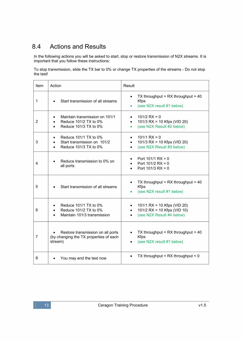
8.4 Actions and Results
In the following actions you will be asked to start, stop or restore transmission of N2X streams. It is important that you follow these instructions:
To stop transmission, slide the TX bar to 0% or change TX properties of the streams - Do not stop the test!
Item Action Result
1 • Start transmission of all streams
• TX throughput = RX throughput = 40 Kfps
• (see N2X result #1 below)
2
• Maintain transmission on 101/1
• Reduce 101/2 TX to 0%
• Reduce 101/3 TX to 0%
• 101/2 RX = 0
• 101/3 RX = 10 Kfps (VID 20)
• (see N2X Result #2 below)
3
• Reduce 101/1 TX to 0%
• Start transmission on 101/2
• Reduce 101/3 TX to 0%
• 101/1 RX = 0
• 101/3 RX = 10 Kfps (VID 20)
• (see N2X Result #3 below)
4 • Reduce transmission to 0% on
all ports
• Port 101/1 RX = 0
• Port 101/2 RX = 0
• Port 101/3 RX = 0
5 • Start transmission of all streams
• TX throughput = RX throughput = 40 Kfps
• (see N2X result #1 below)
6
• Reduce 101/1 TX to 0%
• Reduce 101/2 TX to 0%
• Maintain 101/3 transmission
• 101/1 RX = 10 Kfps (VID 20)
• 101/2 RX = 10 Kfps (VID 10)
• (see N2X Result #4 below)
7 • Restore transmission on all ports
(by changing the TX properties of each stream)
• TX throughput = RX throughput = 40 Kfps
• (see N2X result #1 below)
8 • You may end the test now • TX throughput = RX throughput = 0

14 Ceragon Training Procedure v1.5
8.5 N2X Results (Screenshots)
N2X Result #1:
Port 101/1 ON
Port 101/2 ON
Port 101/3 ON
N2X Result #2:
Port 101/1 ON
Port 101/2 OFF
Port 101/3 OFF
N2X Result #3:
Port 101/1 OFF
Port 101/2 ON
Port 101/3 OFF
N2X Result #4:
Port 101/1 OFF
Port 101/2 OFF
Port 101/3 ON

15 Ceragon Training Procedure v1.5
9.0 Setup #3: CN-PN-PN-PN (Metro Switch)
9.1 Setup Description
In this setup we configure basic scenario for Q-in-Q:
IDU-A receives two customer trunks (CN-Customer Network), each identified by a unique C-
VLAN ID.
The Radio link is configured as PN (Provider Network) with S-Tag set to 200
(Ether-Type can be set to 0x88A8, 0x8100, 0x9100 or 0x9200).
IDU-B removes S-VLAN and delivers both C-VLANs on port #2.
N2X is used to generate and receive L2 streams.
Both IDUs are managed out of band by IP-10 EMS (connected via a switch).
(Some attributes may not appear properly when printed in B&W)
CN Port
#2
PN Port #8
(S-VLAN
200)
PN Port #8
(S-VLAN
200)
CN Port
#3
PN Port #2
(S-VLAN
200)
IDU-A
IDU-B

16 Ceragon Training Procedure v1.5
9.2 Setup Diagram
Port 101/3: 2 streams:
(N2X as a PN port…)
Stream #1:
• Frame size 100 bytes
• 1st tag: S-VLAN 200
• 2nd tag: VID 20
• Layer 2
• SA – 00:00:C0:01:01:11
• DA – 00:00:C0:01:01:01
• Destination port: 101/1
Stream #2:
• Frame size 100 bytes
• 1st tag: S-VLAN 200
• 2nd tag: VID 10
• Layer 2
• SA – 00:00:C0:01:01:12
• DA – 00:00:C0:01:01:02
• Destination port: 101/2
192.168.1.11 192.168.1.1
ODU ODU 2 7
N2X Port 3
Rj45
Port 2
Rj45
ETH
cable
SMA RF cables +
30dB Attenuators
8
Port 101/1 Stream #1:
• Frame size 100 bytes
• 10,000 frames per second
• VID 20
• Layer 2
• SA – 00:00:C0:01:01:01
• DA – 00:00:C0:01:01:11
• Destination port: 101/3
Port 101/2 Stream #2:
• Frame size 100 bytes
• 10,000 frames per second
• VID 10
• Layer 2
• SA – 00:00:C0:01:01:02
• DA – 00:00:C0:01:01:12
• Destination port: 101/3
IDU-A IDU-B
CN
VID 200
VID 10
3
CN
PN (200)
2 7 8 3
PN (200)
PN (200)
Port 1
Rj45
VID 20
EMS
Out of
band MNG Switch
192.168.1.123

17 Ceragon Training Procedure v1.5
9.3 Setup Configuration
1. Switch mode remains in Metro Mode (no change from previous setup)
2. Create VID 200 on both switches (no change from previous setup)
3. IDU-A: Enable port #2 as CN, default VID =200 (no change from previous setup)
4. IDU-A: Enable port #3 as CN, default VID=200 (no change from previous setup)
5. IDU-A: Set port #8 as PN (no change from previous setup)
6. IDU-B: Set port #8 as PN (no change from previous setup)
7. IDU-B: Enable port #2 as PN, allow VID 200, make sure Port Learning is Enabled
8. To configure the N2X, continue to next step

18 Ceragon Training Procedure v1.5
9.4 N2X Configuration
1. Port 101/1 and Port 101/2 remain with no change
2. Port 101/3 needs to be configured as PN. You need to add S-VLAN to each stream. Use the following screen shots as reference:
Port 101/3 stream 2
S-VLAN = 200
Ether-Type 0x88A8
(Make sure EMS settings correlate)
C-VLAN = 10
Ether-Type 0x8100
Port 101/3 stream 1
S-VLAN = 200
Ether-Type 0x88A8
(Make sure EMS settings correlate)
C-VLAN = 20
Ether-Type 0x8100

19 Ceragon Training Procedure v1.5
9.5 Actions and Results
In the following actions you will be asked to start, stop or restore transmission of N2X streams. It is important that you follow these instructions:
To stop transmission, slide the TX bar to 0% or change TX properties of the streams - Do not stop the test!
Item Action Result
1 • Start transmission on all streams
• TX throughput = RX throughput = 40 Kfps
• See N2X result #1 below
2
• Maintain transmission for 101/1
• Maintain transmission for 101/2
• Reduce 101/3 TX to 0%
• Port 101/1 RX = 0
• Port 101/2 RX = 0
• Port 101/3 RX = 20 Kfps
• See N2X result #2 below
3 • Restore transmission on all
streams
• TX throughput = RX throughput = 40 Kfps
• See N2X result #1 below
4
• Reduce 101/1 TX to 0%
• Reduce 101/2 TX to 0%
• Maintain 101/3 transmission
• 101/2 RX = 10 Kfps
• 101/2 RX = 10 Kfps
• 101/3 RX = 0
• See N2X Result #3 below
5 • Restore transmission on all
streams
• TX throughput = RX throughput = 40 Kfps
• See N2X result #1 below
6
• Maintain 101/1 TX to 10 Kfps
• Reduce 101/2 TX to 0%
• Maintain 101/3 transmission
• 101/2 RX = 10 Kfps
• 101/2 RX = 10 Kfps
• 101/3 RX = 10 Kfps
• See N2X Result #4 below
5 • Restore transmission on all
streams
• TX throughput = RX throughput = 40 Kfps
• See N2X result #1 below
6
• Maintain 101/1 TX to 10,000 fps
• Reduce 101/2 TX to 0%
• Reduce 101/2 TX to 0%
• 101/2 RX = 0
• 101/2 RX = 0
• 101/3 RX = 10 Kfps
• See N2X Result #5 below
7 • You may end the test now • TX throughput = RX throughput = 0

20 Ceragon Training Procedure v1.5
9.6 N2X Results (Screenshots)
N2X Result #1:
Port 101/1 ON
Port 101/2 ON
Port 101/3 ON
N2X Result #2:
Port 101/1 ON
Port 101/2 ON
Port 101/3 OFF
N2X Result #3:
Port 101/1 OFF
Port 101/2 OFF
Port 101/3 ON
N2X Result #4:
Port 101/1 ON
Port 101/2 OFF
Port 101/3 ON

21 Ceragon Training Procedure v1.5
N2X Result #5:
Port 101/1 ON
Port 101/2 OFF
Port 101/3 OFF