90-01/690-01 (page 1) standards* 150 class 300 class class end ... cc maximum grooved end — —...
TRANSCRIPT
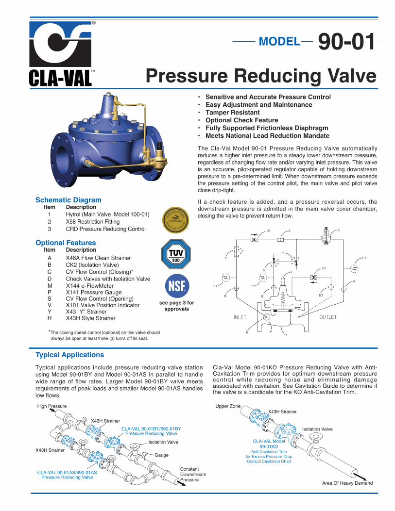
Pressure Reducing Valve
Typical Applications
Typical applications include pressure reducing valve stationusing Model 90-01BY and Model 90-01AS in parallel to handlewide range of flow rates. Larger Model 90-01BY valve meetsrequirements of peak loads and smaller Model 90-01AS handleslow flows.
Schematic Diagram Item Description
1 Hytrol (Main Valve Model 100-01) 2 X58 Restriction Fitting 3 CRD Pressure Reducing Control
Optional Features Item Description
A X46A Flow Clean Strainer B CK2 (Isolation Valve) C CV Flow Control (Closing)* D Check Valves with Isolation Valve
M X144 e-FlowMeter
P X141 Pressure Gauge S CV Flow Control (Opening) V X101 Valve Position Indicator Y X43 "Y" Strainer H X43H Style Strainer
*The closing speed control (optional) on this valve shouldalways be open at least three (3) turns off its seat.
High Pressure
Isolation Valve
Gauge
ConstantDownstreamPressure
CLA-VAL 90-01BY/690-01BYPressure Reducing Valve
CLA-VAL 90-01AS/690-01AS Pressure Reducing Valve
X43H Strainer
• Sensitive and Accurate Pressure Control
• Easy Adjustment and Maintenance
• Tamper Resistant
• Optional Check Feature
• Fully Supported Frictionless Diaphragm
• Meets National Lead Reduction Mandate
The Cla-Val Model 90-01 Pressure Reducing Valve automaticallyreduces a higher inlet pressure to a steady lower downstream pressure,regardless of changing flow rate and/or varying inlet pressure. This valveis an accurate, pilot-operated regulator capable of holding downstreampressure to a pre-determined limit. When downstream pressure exceedsthe pressure setting of the control pilot, the main valve and pilot valveclose drip-tight.
If a check feature is added, and a pressure reversal occurs, thedownstream pressure is admitted in the main valve cover chamber,closing the valve to prevent return flow.
Upper Zone
Isolation Valve
Area Of Heavy Demand
X43H Strainer
CLA-VAL Model90-01KO
Anti-Cavitation Trimfor Excess Pressure DropConsult Cavitation Chart
Cla-Val Model 90-01KO Pressure Reducing Valve with Anti-Cavitation Trim provides for optimum downstream pressurecontrol while reducing noise and eliminating damageassociated with cavitation. See Cavitation Guide to determine ifthe valve is a candidate for the KO Anti-Cavitation Trim.
MODEL 90-01
SUD
see page 3 for
approvals
X43H Strainer
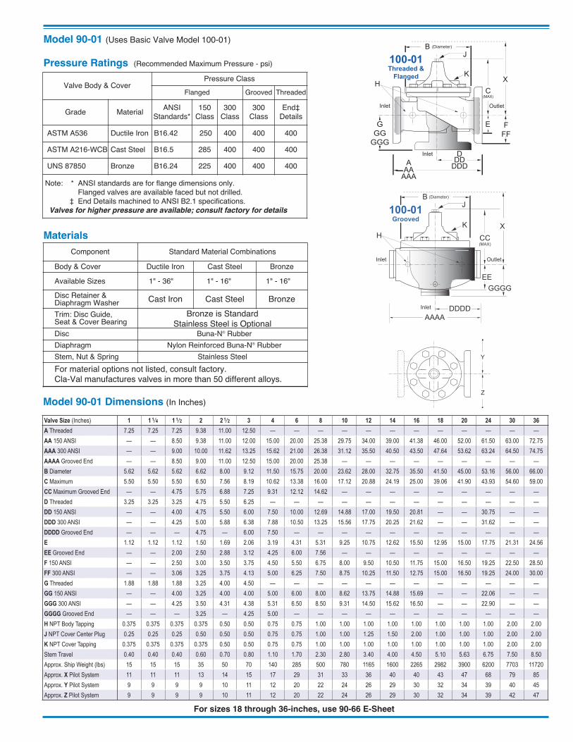
For sizes 18 through 36-inches, use 90-66 E-Sheet
Model 90-01 (Uses Basic Valve Model 100-01)
Model 90-01 Dimensions (In Inches)
Component Standard Material Combinations
Body & Cover Ductile Iron Cast Steel Bronze
Available Sizes 1" - 36" 1" - 16" 1" - 16"
Disc Retainer &Diaphragm Washer Cast Iron Cast Steel BronzeTrim: Disc Guide, Seat & Cover Bearing
Bronze is StandardStainless Steel is Optional
Disc Buna-N® RubberDiaphragm Nylon Reinforced Buna-N® RubberStem, Nut & Spring Stainless SteelFor material options not listed, consult factory.Cla-Val manufactures valves in more than 50 different alloys.
Materials
GGGG
DDDDInlet
AAAA
X
100-01Grooved
EE
CC(MAX)
K
J
H
Inlet Outlet
B (Diameter)
Y
Z
GGGGGG
DInletDDDDD
FFF
X
100-01Threaded &
Flanged
A
E
C(MAX)
K
J
H
Inlet Outlet
AAAAA
B (Diameter)
Valve Body & CoverPressure Class
Flanged Grooved Threaded
Grade Material ANSIStandards*
150Class
300Class
300Class
End‡Details
ASTM A536 Ductile Iron B16.42 250 400 400 400
ASTM A216-WCB Cast Steel B16.5 285 400 400 400
UNS 87850 Bronze B16.24 225 400 400 400
Note: * ANSI standards are for flange dimensions only. Flanged valves are available faced but not drilled. ‡ End Details machined to ANSI B2.1 specifications.
Valves for higher pressure are available; consult factory for details
Pressure Ratings (Recommended Maximum Pressure - psi)
Valve Size (Inches) 1 1 1⁄4 1 1⁄2 2 2 1⁄2 3 4 6 8 10 12 14 16 18 20 24 30 36A Threaded 7.25 7.25 7.25 9.38 11.00 12.50 — — — — — — — — — — — —AA 150 ANSI — — 8.50 9.38 11.00 12.00 15.00 20.00 25.38 29.75 34.00 39.00 41.38 46.00 52.00 61.50 63.00 72.75AAA 300 ANSI — — 9.00 10.00 11.62 13.25 15.62 21.00 26.38 31.12 35.50 40.50 43.50 47.64 53.62 63.24 64.50 74.75AAAA Grooved End — — 8.50 9.00 11.00 12.50 15.00 20.00 25.38 — — — — — — — — —B Diameter 5.62 5.62 5.62 6.62 8.00 9.12 11.50 15.75 20.00 23.62 28.00 32.75 35.50 41.50 45.00 53.16 56.00 66.00C Maximum 5.50 5.50 5.50 6.50 7.56 8.19 10.62 13.38 16.00 17.12 20.88 24.19 25.00 39.06 41.90 43.93 54.60 59.00CC Maximum Grooved End — — 4.75 5.75 6.88 7.25 9.31 12.12 14.62 — — — — — — — — —D Threaded 3.25 3.25 3.25 4.75 5.50 6.25 — — — — — — — — — — — —DD 150 ANSI — — 4.00 4.75 5.50 6.00 7.50 10.00 12.69 14.88 17.00 19.50 20.81 — — 30.75 — —DDD 300 ANSI — — 4.25 5.00 5.88 6.38 7.88 10.50 13.25 15.56 17.75 20.25 21.62 — — 31.62 — —DDDD Grooved End — — — 4.75 — 6.00 7.50 — — — — — — — — — — —E 1.12 1.12 1.12 1.50 1.69 2.06 3.19 4.31 5.31 9.25 10.75 12.62 15.50 12.95 15.00 17.75 21.31 24.56EE Grooved End — — 2.00 2.50 2.88 3.12 4.25 6.00 7.56 — — — — — — — — —F 150 ANSI — — 2.50 3.00 3.50 3.75 4.50 5.50 6.75 8.00 9.50 10.50 11.75 15.00 16.50 19.25 22.50 28.50FF 300 ANSI — — 3.06 3.25 3.75 4.13 5.00 6.25 7.50 8.75 10.25 11.50 12.75 15.00 16.50 19.25 24.00 30.00G Threaded 1.88 1.88 1.88 3.25 4.00 4.50 — — — — — — — — — — — —GG 150 ANSI — — 4.00 3.25 4.00 4.00 5.00 6.00 8.00 8.62 13.75 14.88 15.69 — — 22.06 — —GGG 300 ANSI — — 4.25 3.50 4.31 4.38 5.31 6.50 8.50 9.31 14.50 15.62 16.50 — — 22.90 — —GGGG Grooved End — — — 3.25 — 4.25 5.00 — — — — — — — — — — —H NPT Body Tapping 0.375 0.375 0.375 0.375 0.50 0.50 0.75 0.75 1.00 1.00 1.00 1.00 1.00 1.00 1.00 1.00 2.00 2.00J NPT Cover Center Plug 0.25 0.25 0.25 0.50 0.50 0.50 0.75 0.75 1.00 1.00 1.25 1.50 2.00 1.00 1.00 1.00 2.00 2.00K NPT Cover Tapping 0.375 0.375 0.375 0.375 0.50 0.50 0.75 0.75 1.00 1.00 1.00 1.00 1.00 1.00 1.00 1.00 2.00 2.00Stem Travel 0.40 0.40 0.40 0.60 0.70 0.80 1.10 1.70 2.30 2.80 3.40 4.00 4.50 5.10 5.63 6.75 7.50 8.50Approx. Ship Weight (lbs) 15 15 15 35 50 70 140 285 500 780 1165 1600 2265 2982 3900 6200 7703 11720Approx. X Pilot System 11 11 11 13 14 15 17 29 31 33 36 40 40 43 47 68 79 85Approx. Y Pilot System 9 9 9 9 10 11 12 20 22 24 26 29 30 32 34 39 40 45Approx. Z Pilot System 9 9 9 9 10 11 12 20 22 24 26 29 30 32 34 39 42 47
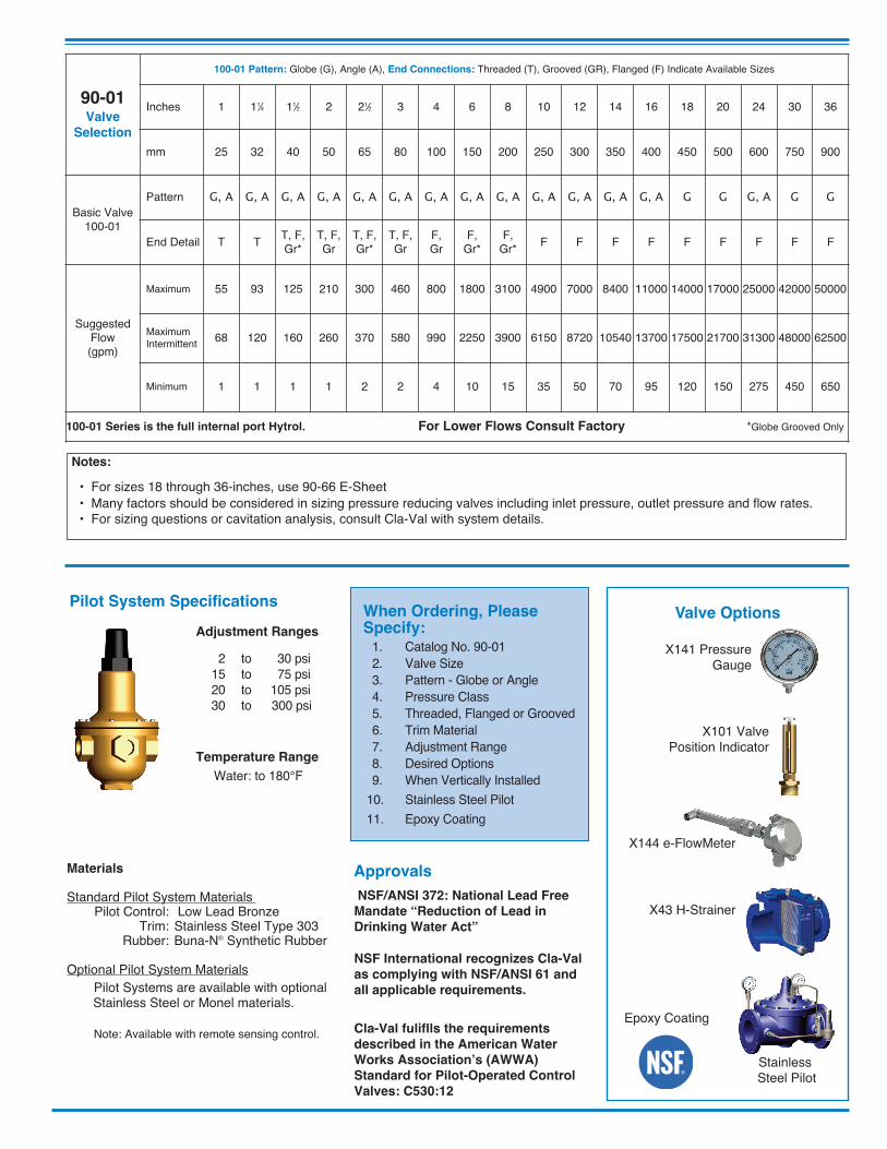
90-01Valve
Selection
100-01 Pattern: Globe (G), Angle (A), End Connections: Threaded (T), Grooved (GR), Flanged (F) Indicate Available Sizes
Inches 1 11⁄4 11⁄2 2 21⁄2 3 4 6 8 10 12 14 16 18 20 24 30 36
mm 25 32 40 50 65 80 100 150 200 250 300 350 400 450 500 600 750 900
Basic Valve100-01
Pattern G, A G, A G, A G, A G, A G, A G, A G, A G, A G, A G, A G, A G, A G G G, A G G
End Detail T T T, F,Gr*
T, F,Gr
T, F,Gr*
T, F,Gr
F, Gr
F, Gr*
F, Gr* F F F F F F F F F
Suggested Flow (gpm)
Maximum 55 93 125 210 300 460 800 1800 3100 4900 7000 8400 11000 14000 17000 25000 42000 50000
Maximum Intermittent 68 120 160 260 370 580 990 2250 3900 6150 8720 10540 13700 17500 21700 31300 48000 62500
Minimum 1 1 1 1 2 2 4 10 15 35 50 70 95 120 150 275 450 650
100-01 Series is the full internal port Hytrol. For Lower Flows Consult Factory *Globe Grooved Only
Adjustment Ranges
2 to 30 psi 15 to 75 psi 20 to 105 psi 30 to 300 psi
Temperature Range
Water: to 180°F
Materials
Standard Pilot System Materials Pilot Control: Low Lead Bronze Trim: Stainless Steel Type 303 Rubber: Buna-N® Synthetic Rubber
Optional Pilot System Materials Pilot Systems are available with optional Stainless Steel or Monel materials. Note: Available with remote sensing control.
When Ordering, PleaseSpecify: 1. Catalog No. 90-01 2. Valve Size 3. Pattern - Globe or Angle 4. Pressure Class 5. Threaded, Flanged or Grooved 6. Trim Material 7. Adjustment Range 8. Desired Options 9. When Vertically Installed10. Stainless Steel Pilot11. Epoxy Coating
Pilot System Specifications
Notes:
• For sizes 18 through 36-inches, use 90-66 E-Sheet • Many factors should be considered in sizing pressure reducing valves including inlet pressure, outlet pressure and flow rates.• For sizing questions or cavitation analysis, consult Cla-Val with system details.
Valve Options
Cla-Val fuliflls the requirements
described in the American Water
Works Association’s (AWWA)
Standard for Pilot-Operated Control
Valves: C530:12
NSF International recognizes Cla-Val
as complying with NSF/ANSI 61 and
all applicable requirements.
NSF/ANSI 372: National Lead Free
Mandate “Reduction of Lead in
Drinking Water Act”
Approvals
X141 PressureGauge
X101 ValvePosition Indicator
X144 e-FlowMeter
X43 H-Strainer
StainlessSteel Pilot
Epoxy Coating

FunctionThe Pressure Reducing Valve shall maintain a constantdownstream pressure regardless of changing flow rate and/orinlet pressure.
"Tying" of equipment into packages for the purpose of thwartingcompetition shall be considered to be in non-compliance withthese specifications. Manufacturers shall price items underdifferent subsections or sections separately.
Main ValveThe valve shall be hydraulically operated, single diaphragm-actuated, globe or angle pattern. The valve shall consist of threemajor components: the body, with seat installed; the cover, withbearings installed; and the diaphragm assembly. The diaphragmassembly shall be the only moving part and shall form a sealedchamber in the upper portion of the valve, separating operatingpressure from line pressure. Packing glands and/or stuffing boxesare not permitted and there shall be no pistons operating the mainvalve or pilot controls.
Main Valve BodyNo separate chambers shall be allowed between the main valvecover and body. Valve body and cover shall be of cast material.Ductile Iron is standard and other materials shall be available. Nofabrication or welding shall be used in the manufacturing process.Total shipping weight shall be equal or greater in all respects tothe Hytrol 100-01 body.
The valve shall contain a resilient, synthetic rubber disc, with arectangular cross-section contained on three and one-half sidesby a disc retainer and forming a tight seal against a singleremovable seat insert. No O-ring type discs (circular, square, orquad type) shall be permitted as the seating surface. The discguide shall be of the contoured type to permit smooth transition offlow and shall hold the disc firmly in place.
The disc retainer shall be of a sturdy one-piece design capable ofwithstanding opening and closing shocks. It must have straightedge sides and a radius at the top edge to prevent excessivediaphragm wear as the diaphragm flexes across this surface. Nohourglass-shaped disc retainers shall be permitted and no V-typeor slotted type disc guides shall be used.
The diaphragm assembly containing a non-magnetic 303stainless steel stem with sufficient diameter to withstand highhydraulic pressures shall be fully guided at both ends by abearing in the valve cover and an integral bearing in the valveseat. No center guides shall be permitted. The stem shall bedrilled and tapped in the cover end to receive and affix suchaccessories as may be deemed necessary. The diaphragmassembly shall be the only moving part and shall form a sealedchamber in the upper portion of the valve, separating operatingpressure from line pressure.
The flexible, non-wicking, FDA approved diaphragm shall consistof nylon fabric bonded with synthetic rubber compatible with theoperating fluid. The center hole for the main valve stem must besealed by the vulcanized process or a rubber grommet sealingthe center stem hole from the operating pressure. The diaphragmmust withstand a Mullins Burst Test of a minimum of 600 psi perlayer of nylon fabric and shall be cycle tested 100,000 times toensure longevity.
The diaphragm shall not be used as the seating surface. Thediaphragm shall be fully supported in the valve body and cover bymachined surfaces which support no less than one-half of thetotal surface area of the diaphragm in either the fully opened orfully closed position.
Bellofram type rolling diaphragms shall not be permitted.
The main valve seat and the stem bearing in the valve cover shallbe removable. The cover bearing and seat in 6" and smaller sizevalves shall be threaded into the cover and body. The valve seatin 8" and larger size valves shall be retained by flat head machinescrews for ease of maintenance. The lower bearing of the valvestem shall be contained concentrically within the seat and shall beexposed to the flow on all sides to avoid deposits. To insureproper alignment of the valve stem, the valve body and covershall be machined with a locating lip. No "pinned" covers to thevalve body shall be permitted. Cover bearing, disc retainer, andseat shall be made of the same material.
All necessary repairs and/or modifications other than replacementof the main valve body shall be possible without removing thevalve from the pipeline. Packing glands and/or stuffing boxesshall not be permitted.
The valve manufacturer shall warrant the valve to be free ofdefects in material and workmanship for a period of three yearsfrom date of shipment, provided the valve is installed and used inaccordance with all applicable instructions. Electrical componentsshall have a one year warranty.
The valve manufacturer shall be able to supply a complete line ofequipment from 1 1/4" through 36" sizes and a complete selectionof complementary equipment. The valve manufacturer shall alsoprovide a computerized cavitation chart which show flow rate,differential pressure, percentage of valve opening, Cv factor,system velocity, and if there will be cavitation damage.
Pilot Control SystemThe pressure reducing pilot control shall be a direct-acting,adjustable, spring-loaded, normally open, diaphragm valvedesigned to permit flow when controlled pressure is less than thespring setting. The pilot control is held open by the force of thecompression on the spring above the diaphragm, and it closeswhen the delivery pressure acting on the underside of thediaphragm exceeds the spring setting. The pilot control systemshall include a fixed orifice. No variable orifices shall be permitted.The pilot system shall include an opening speed control on allvalves 3" and smaller for the model 90-01 as standard equipment.
The pilot control shall have a second downstream sensing portwhich can be utilized to install a pressure gauge. A full range ofspring settings shall be available in ranges of 0 to 450 psi.
A direct factory representative shall be made available for start-upservice, inspection and necessary adjustments.
This valve shall be a Cla-Val Co. Model No. 90-01 PressureReducing Valve. As manufactured by Cla-Val Co. Costa Mesa,CA 92627.
Model 90-01 Purchase Specifications
CLA-VAL 1701 Placentia Ave • Costa Mesa CA 92627 • Phone: 949-722-4800 • Fax: 949-548-5441 • E-mail: [email protected] • www.cla-val.com Copyright Cla-Val 2016 • Printed in USA • Specifications subject to change without notice.©
E-90-01 (R-02/2016)