9 user’s manual 21pmx18-2a pmx18-5a pmx35-1a pmx35-3a pmx70-1a pmx110-0.6a pmx250-0.25a...
TRANSCRIPT

PMX18-2APMX18-5APMX35-1APMX35-3APMX70-1APMX110-0.6APMX250-0.25APMX350-0.2APMX500-0.1A
User’s ManualRegulated DC Power SupplyPMX-A Series
Search by Topic 5Component Names 6
Preparation 9Connecting the Power Cord 10
Turning the Power On 11Load Considerations 13
Load Cables 16Connecting to the Output Terminals 17
Sensing 18
Basic Functions 21Measured Value Display and Setting
Display 22Panel Operations 23
Output Operations 23CC Power Supply and CC Power Supply
24Using the PMX-A Series as a CV or CC
Power Supply 26Protection Functions and Alarms 27
CONFIG Settings 31Preset Memory Function 39
Locking Panel Controls (Key lock) 41Remote Control 41
Factory Default Settings (Initialization)42
External Control 43General Description 44
About the J1 Connector 44Output Terminal Insulation 46
Output Voltage Control 49Output Current Control 51
Controlling the Output On and Off States53
External Monitoring 55
Parallel/Series Operation 57Parallel Operation 58
Series Operation 61
Maintenance 65Calibration 66
Specifications 71
AppendixOptions 86
Troubleshooting 88
Part No. IB027387Nov 2019

2 PMX-A
These manuals are intended for users of the Regulated DCPower Supply and their instructors. It is assumed that thereader has knowledge about electrical aspects of regulatedDC power supplies.
Manual construction Safety information
This document contains general safety precautions for thisproduct. Keep them in mind and make sure to observethem.
User’s manual (this manual, PDF)This document is intended for first-time users of this prod-uct. It provides an overview of the product and notes onusage. It also explains how to configure the product, oper-ate the product, perform maintenance on the product, spec-ifications the product, and so on. To effectively use theproduct features, read this document from beginning to end.We recommend that you read it thoroughly before using thisproduct for the first time.If you forget how to use the product or if a problem occurs,we recommend that you refer to this document again.
Quick referenceThis document explains Panel description and operationbriefly.
Communication Interface Manual (HTML, PDF)This document explains how to control the product remotelyusing commands.The interface manual is written for readers with sufficientbasic knowledge of how to control power supplies using aPC.
PDF and HTML files are included in the accompanying CD-ROM.Adobe Reader is required to view the PDF files.Microsoft Internet Explorer or Google Chrome is required toview the HTML files.The newest version of the manual can be downloaded fromDownload service of Kikusui website.
If you find any misplaced or missing pages in the manuals,they will be replaced. If the manual gets lost or soiled, a newcopy can be provided for a fee. In either case, please contactyour Kikusui agent or distributor. At that time, inform youragent or distributor of the “Part No.” written on the front coverof this manual.Every effort has been made to ensure the accuracy of thismanual. However, if you have any questions or find any errorsor omissions, please contact your Kikusui agent or distributor.After you have finished reading this manual, store it so thatyou can use it for reference at any time.
Firmware versions that this manual coversThis manual covers IFC firmware versions 1.5X, IOC firmwareversions 1.1X.When contacting us about the product, please provide us with:
The model (marked in the top section of the front panel)The firmware version (see page 11)The serial number (marked on the rear panel)
TrademarksMicrosoft, Windows, and Visual Basic are registered trade-marks of Microsoft Corporation in the United States and/orother countries.All company names and product names used in this manualare trademarks or registered trademarks of their respectivecompanies.
CopyrightsThe contents of this guide may not be reproduced, in whole orin part, without the prior consent of the copyright holder.The specifications of this product and the contents of thisguide are subject to change without prior notice.Copyright © 2013 Kikusui Electronics Corporation
About the PMX-A Manuals

PMX-A 3
The PMX-A Series is a lineup of easy-to-use, compact regu-lated DC power supplies.It can be controlled remotely through the standard-equippedcommunication feature.
FeaturesCommunication feature
RS232C, USB, and LAN interfaces are all installed as stan-dard.The remote interfaces comply with IEEE Std 488.2-1992and SCPI Specification 1999.0.Because the LAN interface complies with the LXI standard,the construction of a highly cost-effective system is possi-ble.
Setting preset featureYou can save up to three sets of output settings (the combi-nation of the voltage value and current value). You can sim-ply select a set of output settings that you want to use ratherthan having to specify each setting every time.
External controlExternal analog signals can be used to control the outputvoltage and current, turn the output on and off, and monitorthe operation mode.
Remote sensing (equipped on models whose rated output voltage is 18 V or 35 V)
Remote sensing stabilizes the output voltage across theload by reducing the influence of voltage drops and othereffects caused by the load cable resistance.
Standard protection functionsThe PMX-A series is equipped with standard overvoltageprotection (OVP), overcurrent protection (OCP), and over-heat protection (OHP) functions. When a protection functionis activated, the cause of it is indicated on the front paneldisplay area. The output is turned off to protect the productand the load.
When using this product, be sure to observe the “SafetyPrecautions” in the Safety information manual.
When installing this product, be sure to observe the“Precautions Concerning Installation Location” in theSafety information manual. The following precautionspertain only to this product.• When installing this product, be sure to observe the tem-
perature and humidity ranges indicated below.Operating temperature range: 0 °C to +40 °C (32 °F to 104 °F)Operating humidity range: 20 %rh to 85 %rh (no condensation)
• When storing this product, be sure to observe the tempera-ture and humidity ranges indicated below.Storage temperature range: -25 °C to +70 °C (-13 °F to 158 °F)Storage humidity range: 90 %rh or less (no condensation)
• In this manual, the PMX-A Series Regulated DC PowerSupply is referred to as the “PMX-A.”
• The term “PC” is used to refer generally to both personalcomputers and workstations.
• The screen captures used in this manual may differ from theactual screens that appear on the PMX-A series. Thescreen captures are merely examples.
• The following markings are used in the explanations in thismanual.
Indicates a potentially hazardous situation which, ifignored, could result in death or serious injury.
Indicates a potentially hazardous situation which, ifignored, may result in damage to the product or otherproperty.
Indicates information that you should know.
Explanation of terminology or operation principle.
Indicates a reference to detailed information.
Indicates a reference to a manual containing detailedinformation.
CFxx:x“CF” indicates that this is a CONFIG parameter. The twodigits after CF indicate the CONFIG parameter number.The value after the colon indicates the selected setting.
SHIFT+key name (blue letters)Indicates an operation that requires you to press a keyindicated in blue characters (below the key) while holdingdown the SHIFT key.
Indicates useful information.
Model Maximum operatingcurrent
Maximum operatingvoltage
Power
PMX18-2A 2 A 18 V 36 WPMX18-5A 5 A 18 V 90 WPMX35-1A 1 A 35 V 35 WPMX35-3A 3 A 35 V 105 WPMX70-1A 1 A 70 V 70 WPMX110-0.6A 0.6 A 110 V 66 WPMX250-0.25A 0.25 A 250 V 62.5 WPMX350-0.2A 0.2 A 350 V 70 WPMX500-0.1A 0.1 A 500 V 50 W
Product Overview
Safety Precautions
Precautions ConcerningInstallation Location
Notations Used in This Guide
WARNING
CAUTION
DESCRIPTION
See
Memo

4 PMX-A
Contents
About the PMX-A Manuals ....................2Product Overview ..................................3Safety Precautions .................................3Precautions Concerning Installation Loca-tion .........................................................3Notations Used in This Guide ................3Search by Topic......................................5Component Names .................................6
1 PreparationConnecting the Power Cord........................ 10Turning the Power On................................. 11
Turning the POWER switch on ............ 11Turning the POWER switch off ............ 12
Load Considerations................................... 13Load Cables................................................ 16Connecting to the Output Terminals ........... 17Sensing....................................................... 18
Local sensing ....................................... 18Remote sensing (equipped only on models whose rated output voltage is 18 V or 35 V) .................................................... 18
2 Basic FunctionsMeasured Value Display and Setting Display.. 22Panel Operations ........................................ 23Output Operations ...................................... 23CC Power Supply and CC Power Supply ... 24Using the PMX-A Series as a CV or CC Power Supply......................................................... 26Protection Functions and Alarms................ 27
Alarm occurrence and clearing alarms 27Protection function activation ............... 28
CONFIG Settings........................................ 31CONFIG parameter details .................. 35
Preset Memory Function............................. 39Saving settings to preset memory........ 39Recalling preset memory entries ......... 40
Locking Panel Controls (Key lock).............. 41Remote Control........................................... 41Factory Default Settings (Initialization) ....... 42
3 External ControlGeneral Description .................................... 44About the J1 Connector .............................. 44Output Terminal Insulation.......................... 46
When the output terminal is not grounded (floating) .............................................. 46When the output terminal is grounded 47Cautions when using the external voltage (Vext)................................................... 48
Output Voltage Control .............................. 49Control using an external voltage (Vext) ... 49Control using an external resistance (Rext) 50
Output Current Control............................... 51Control using an external voltage (Vext) ... 51Control using an external resistance (Rext) 52
Controlling the Output On and Off States .. 53External Monitoring .................................... 55
4 Parallel/Series Opera-tionParallel Operation ...................................... 58
Parallel operation features .................. 58Parallel operation connection.............. 59Parallel operation settings................... 60Starting parallel operation ................... 60
Series Operation ........................................ 61Series operation features .................... 61Series operation connection................ 62Series operation settings..................... 63Starting series operation ..................... 63
5 MaintenanceCalibration.................................................. 66
Calibration overview............................ 66Calibration procedure.......................... 67
6 SpecificationsPMX18-2A/ PMX18-5A/ PMX35-1A/ PMX35-3A........................................... 72PMX70-1A/ PMX110-0.6A/ PMX250-0.25A/ PMX350-0.2A/ PMX500-0.1A.. 78
AppendixA Options .................................. 86
B Troubleshooting..................... 88

PMX-A 5
Search by Topic
TroubleshootingSee “Troubleshooting” on page 88.
• I want to check the accessories. →See the included packing list. —• The installation space is limited, so I want
to check the installation conditions.→See the included “Safety information”
document, or the electronic version of the document on the CD-ROM.
—
• How do I connect the AC power supply? →“Connecting the Power Cord” p.10• What kind of load cables should I use? →“Load Cables” p.16• How do I ensure stable voltage when the
cables connected to the load are long (the distance to the load is long)?
→“Sensing”p.18
• How do I rack mount the PMX-A series? What kind of parts are needed?
→“Rack mount option” p.86
• How do I use remote sensing to stabilize the PMX-A series?
→“Sensing” p.18
• How do I set the protection functions to prevent damage to the load?
→“Protection Functions and Alarms” p.27
• After a protection function has been acti-vated, how do I restart tests automatically when the cause of the alarm is fixed?
→“Alarm occurrence and clearing alarms”p.27
• How do I set the communication condi-tions for remote control?
→See the Communication Interface Man-ual on the included CD-ROM. —
• How do I check the settings in preset memory?
→“Recalling preset memory entries” p.40
• How do I reset the PMX-A series to its fac-tory default settings?
→“Factory Default Settings (Initialization)” p.42
• How do I use the PMX-A series as a con-stant voltage power supply (CV mode)?
→“Using the PMX-A Series as a CV or CC Power Supply”
p.26• How do I use the PMX-A series as a con-
stant current power supply (CC mode)?• How do I operate the PMX-A series at a
specific current? How do I save current values to the preset memory?
→“Preset Memory Function”p.39
• How do I control the output voltage with an external DC voltage?
→“Output Voltage Control” p.49
• How do I monitor the output voltage and output current?
→“External Monitoring” p.55
• How do I prevent the settings from being changed?
→“Locking Panel Controls (Key lock)” p.41
• How do I clean the PMX-A series? →See the included “Safety information” document, or the electronic version of the document on the CD-ROM.
—
• How do I calibrate the PMX-A series? →“Calibration” p.66
Preparation
Setup
Operation
Maintenance

6 PMX-A
Component Names
Front Panel
ON
SENSING
AWG20-14
+S
-S
STRIP- GAUGE
7mm
PMX35-3A 0-35V 3A
REGULATED DC POWER SUPPLY
CBA SHIFTALM CLR
FINE
FINE
CURRENT
VOLTAGE
OVP・OCPSET LOCKCONFIG LOCAL
OUTPUTCV
CC
A
V
REMOTELAN LOCKALARM
PRESET B CA
CV
CC
A
V
REMOTELAN LOCKALARM
PRESET B CA
DC OUTPUT0-35V
3A OFF
CV
CC
A
V
REMOTELAN LOCKALARM
PRESET B CA
4
20
2221
23
24
25
89101112
6
1 3
5
19
7
16 17 181514
13
2
4
8910
6
1 3
25
5
7
16 17 181514
13
2
PMX18-2A, PMX18-5A, PMX35-1A, PMX35-3A
PMX70-1A, PMX110-0.6A,PMX250-0.25A, PMX350-0.2A,PMX500-0.1A
Display area (Common)
Display area
Display area
PMX-A 7
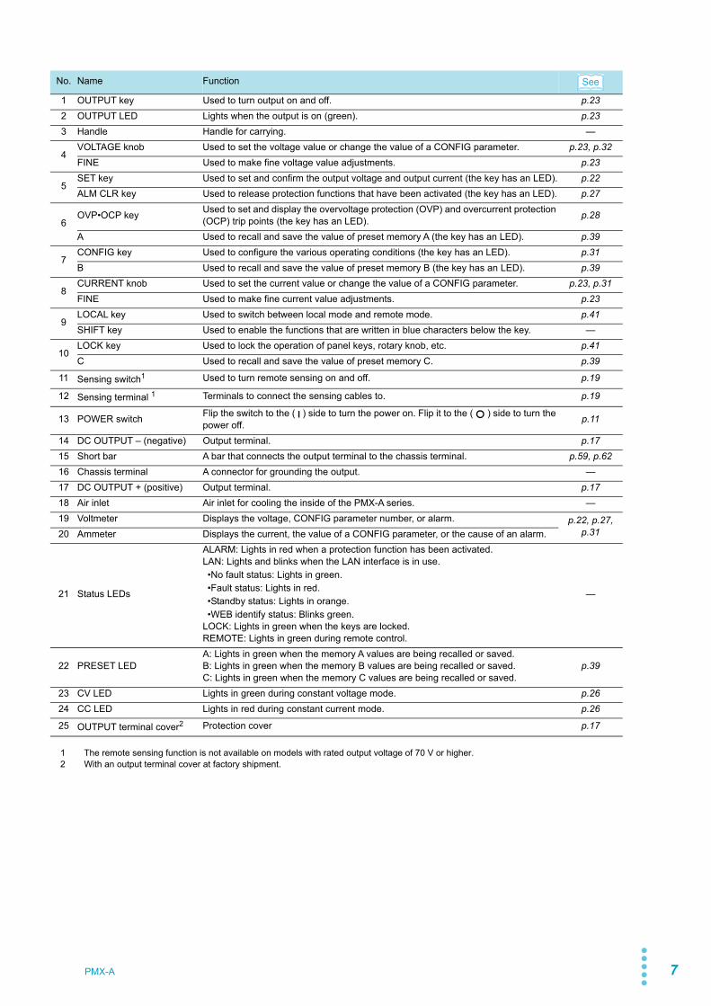
No. Name Function
1 OUTPUT key Used to turn output on and off. p.232 OUTPUT LED Lights when the output is on (green). p.233 Handle Handle for carrying. —
4VOLTAGE knob Used to set the voltage value or change the value of a CONFIG parameter. p.23, p.32FINE Used to make fine voltage value adjustments. p.23
5SET key Used to set and confirm the output voltage and output current (the key has an LED). p.22ALM CLR key Used to release protection functions that have been activated (the key has an LED). p.27
6OVP•OCP key Used to set and display the overvoltage protection (OVP) and overcurrent protection
(OCP) trip points (the key has an LED). p.28
A Used to recall and save the value of preset memory A (the key has an LED). p.39
7CONFIG key Used to configure the various operating conditions (the key has an LED). p.31B Used to recall and save the value of preset memory B (the key has an LED). p.39
8CURRENT knob Used to set the current value or change the value of a CONFIG parameter. p.23, p.31FINE Used to make fine current value adjustments. p.23
9LOCAL key Used to switch between local mode and remote mode. p.41SHIFT key Used to enable the functions that are written in blue characters below the key. —
10LOCK key Used to lock the operation of panel keys, rotary knob, etc. p.41C Used to recall and save the value of preset memory C. p.39
11 Sensing switch1
1 The remote sensing function is not available on models with rated output voltage of 70 V or higher.
Used to turn remote sensing on and off. p.19
12 Sensing terminal 1 Terminals to connect the sensing cables to. p.19
13 POWER switch Flip the switch to the ( ) side to turn the power on. Flip it to the ( ) side to turn the power off. p.11
14 DC OUTPUT – (negative) Output terminal. p.1715 Short bar A bar that connects the output terminal to the chassis terminal. p.59, p.6216 Chassis terminal A connector for grounding the output. —17 DC OUTPUT + (positive) Output terminal. p.1718 Air inlet Air inlet for cooling the inside of the PMX-A series. —19 Voltmeter Displays the voltage, CONFIG parameter number, or alarm. p.22, p.27,
p.3120 Ammeter Displays the current, the value of a CONFIG parameter, or the cause of an alarm.
21 Status LEDs
ALARM: Lights in red when a protection function has been activated.LAN: Lights and blinks when the LAN interface is in use. •No fault status: Lights in green. •Fault status: Lights in red. •Standby status: Lights in orange. •WEB identify status: Blinks green.LOCK: Lights in green when the keys are locked.REMOTE: Lights in green during remote control.
—
22 PRESET LEDA: Lights in green when the memory A values are being recalled or saved.B: Lights in green when the memory B values are being recalled or saved.C: Lights in green when the memory C values are being recalled or saved.
p.39
23 CV LED Lights in green during constant voltage mode. p.2624 CC LED Lights in red during constant current mode. p.26
25 OUTPUT terminal cover2
2 With an output terminal cover at factory shipment.
Protection cover p.17
See

8 PMX-A
No. Name Function
1 USB USB port for controlling the PMX-A series remotely.
Interface manual2 RS232C RS232C port for controlling the PMX-A series remotely.3 LAN Ethernet port for controlling the PMX-A series remotely.4 Air outlet Air outlet for cooling the inside of the PMX-A series. —5 AC INPUT AC inlet. p.106 J1 External control connector. p.44
7 S1 Maintenance switch.1
1 Kikusui service engineers use this switch only during maintenance and servicing. Normally, the LED is off when the switch is on the opposite side of .
—
J1RS232C LANUSBS1
AC INPUT
LINEVOLTAGE
100V
117V
200V217V
234V
SETTINGSUPPLY
5
6
7
31 2
4
Rear Panel
See
PreparationThis chapter describes how to turn on thePMX-A series, what kind of load cables touse, and how to connect cables to the out-put connectors.For information about installing and movingthis product, see “Precautions ConcerningInstallation Location” and “Precautions toBe Taken When Moving the Product” in theSafety information manual.When using or storing this product, be sureto observe the temperature and humidityranges. For environmental conditions, see“General specifications“ (p.77, p.83).If you want to mount the product on a rack,see “Rack mount option“ (p.86).

10 PMX-A
Connecting the Power Cord
This product conforms to IEC Overvoltage Category II (energy-consuming equipment that issupplied from a fixed installation).
1 Check that the AC power line meets the nominal input rating of the product.The nominal input rating of this product is indicated on the rear panel. The productaccepts 50 Hz or 60 Hz.
The supply voltage is set before factory shipment by a Kikusui ser-vice engineer. If the voltage is set to another setting, a mark will beindicated to the left of the appropriate voltage.Be sure to check the nominal input rating before connecting thepower cord.
The example of supply voltage 100 Vac
2 Check that the POWER switch is turned off.
3 Connect the power cord to the AC inlet on the rear panel.
4 Insert the power plug into a grounded outlet.
WARNING Risk of electric shock.• This product conforms to IEC Safety Class I (equipment that has a protective con-
ductor terminal). Be sure to earth ground the product to prevent electric shock.• The product is grounded through the power cord ground wire. Connect the protec-
tive conductor terminal to earth ground.
• Use the supplied power cord to connect to the AC line.If the supplied power cord cannot be used because the rated voltage or the plug shape is incompatible, have a qualified engineer replace it with an appropriate power cord that is 3 m or less in length. If obtaining a power cord is difficult, contact your Kikusui agent or dis-tributor.
• The power cord with a plug can be used to disconnect the PMX-A series from the AC power line in an emergency. Connect the plug to an easily accessible power outlet so that the plug can be removed from the outlet at any time. Be sure to provide adequate clear-ance around the power outlet.
• Do not use the supplied power cord with other instruments.
LINEVOLTAGE
100V
117V
200V217V
234V
SETTINGSUPPLY
●

PMX-A 11
Prep
arat
ion
1
Turning the Power On
Turning the POWER switch on
p.42 When you turn the POWER switch on for the first time after purchase, the PMX-A seriesstarts with its factory default settings. Subsequent times that you turn the PMX-A series on, itstarts with the panel settings (excluding the output on/off setting) that were in use immedi-ately before the POWER switch was turned off.
p.35 You can use the CONFIG settings (CF01) to select the output state of the PMX-A series whenthe POWER switch is turned on.
1 Check that the power cord is connected correctly.
2 Turn the POWER switch on ( ).All the LEDs light, and then the voltmeter and the ammeter display the followingsequence of information: the rated voltage and rated current, the IOC firmware ver-sion, the IFC firmware version, and then the selected interface. Each item is displayedfor approximately 1 second. Two firmware versions, IOC and IFC, are displayed.After a few seconds, the PMX-A series enters the operation standby state (the outputvalue is displayed).
p.88, p.90 If you select the LAN interface and the interface display remains showing (for approximately30 seconds) when the POWER switch is turned on, the PMX-A series is waiting for aresponse from the DHCP server.
Inrush current
p.72, p.78 When the POWER switch is turned on, an inrush current flows. Check that sufficient currentcapacity is available in the AC power line or the switchboard, particularly if you are using mul-tiple PMX-As and turning on their POWER switches simultaneously.For the inrush current of each model, “Specifications“.
CAUTION You can use the CONFIG settings to set how the PMX-A series starts when you turn the POWER switch on. Depending on the setting, the output may be turned on automatically when the POWER switch is turned on. If you connect a load without setting OVP and OCP to the appropriate values, the load may be damaged if output automatically turns on when the power is turned on.
See
See
CV
CC
A
V
CV
CC
A
V
CV
CC
A
V
CV
CC
A
V
IOC firmware version display(Version 1.10 in this example)
Rated voltage and rated current display(PMX18-5A in this example)
IFC firmware version display(Version 1.00 in this example)
Interface display(The LAN interface is selected in this example.)
See
See

12 PMX-A
Turning the Power On
Turning the POWER switch off
Flip the POWER switch to the ( ) side to turn the PMX-A series off.The PMX-A series saves the panel settings (except the output on/off setting) that were in useimmediately before the POWER switch was turned off.
p.35 You can use the CONFIG settings (CF01) to select how the PMX-A series starts when thePOWER switch is turned on.If the POWER switch is turned off immediately after the settings have been changed, the lastsettings may not be stored.
See
CAUTION After you turn the POWER switch off, wait at least 10 seconds after the panel display turns off before you turn the POWER switch back on. Repeatedly turning the POWER switch on and off at short intervals can cause damage to the inrush current limiter. Furthermore, this will shorten the service life of the POWER switch and the internal input fuse.

PMX-A 13
Prep
arat
ion
1
Load Considerations
Note that the output will become unstable if the following types of loads are connected.
Loads with peak current or pulse-shaped currentThe PMX-A series only indicates mean values. Even when the indicated value is less than orequal to the set constant current, the peak values may exceed the set constant current. If thishappens, the PMX-A series is instantaneously put into constant-current mode, and the outputvoltage drops.For these types of loads, you must increase the set constant current or increase the currentcapacity.
Loads that generate reverse current to the power supplyThe PMX-A series cannot absorb reverse current from the load. Therefore, if a regenerativeload (such as an inverter, converter, or transformer) is connected, the output voltageincreases and becomes unstable. This can cause a malfunction. For these types of loads, connect a resistor (RD) as shown in the following figure to bypassthe reverse current. However, the amount of current to the load decreases by Irp.
Load current with peaks Pulse-shaped load current
Constant current settingAmmeter reading (mean value)
Constant current settingAmmeter reading (mean value)
IO
RDEO
Equivalent circuit of the PMX-A Regenerative load
− +
0
Reverse current-IO
+IO
Irp
RD[Ω] ≤
RD: Reverse current bypass dummy loadEO: Output voltageIrp: Maximum reverse current
Load
EO[V]Irp[A]
Out
put c
urre
nt
wav
efor
m
CAUTION Use a resistor with sufficient rated power for RD. If a resistor with insufficient rated power for the circuit is used, resistor RD will burn out.

14 PMX-A
Load Considerations
Loads with accumulated energyConnecting a load with accumulated energy, such as a battery, to the PMX-A series maycause current to flow from the load to the internal circuit of the PMX-A series. This currentmay damage the PMX-A series or reduce the life of the load.For this type of load, connect a reverse-current-prevention diode (DRP) between the PMX-Aseries and the load in series as shown in the following figure.This cannot be used in conjunction with remote sensing.
PMX-A Load with accumulated energy
DRP: Reverse-current-protection diodeDRP
CAUTION • To protect the load and the PMX-A series, use a DRP that conforms to the following specifi-cations.Reverse voltage withstand capacity: At least twice the rated output voltage of the PMX-A series.Forward current capacity: 3 to 10 times the rated output current of the PMX-A series.A diode with small loss.
• Be sure to take into account the heat generated by DRP. DRP will burn out with inadequate heat dissipation.

PMX-A 15
Load Considerations
Prep
arat
ion
1
Sink current from an external voltage sourceDirectly connecting an external voltage source to the PMX-A series may cause sink current toflow from the internal breeder circuit of the PMX-A series. This current may damage the PMX-A series or reduce the life of the load.For this type of sink current, you need to connect a diode to the load cable or mechanicallyseparate the load cable from the PMX-A series with a switch or the like.Depending on the power-off or output-off state, the sink current that flows when an externalvoltage source is connected will vary.The sink current is reduced at a low output terminal voltage. Hardly any sink current flowsnear 0 V. The sink currents indicated here are standard values.
Sink current from an external voltage source when the power is off or theoutput is off
Vout = Output terminal voltage
Vout = Output terminal voltage
Vout = Output terminal voltage
Vout = Output terminal voltage
Vout = Output terminal voltage
Vout = Output terminal voltage
Vout = Output terminal voltage
Model State UnitSink current
1 Vout 2 Vout 5 Vout 10 Vout 15 Vout 18 VoutPMX18-2APMX18-5A
POWER offmA
4.2 8.6 21.9 44.1 66.4 79.8Output off 4.2 8.3 20.6 41.2 61.8 74.2
Model State UnitSink current
2 Vout 5 Vout 10 Vout 15 Vout 20 Vout 25 Vout 30 Vout 35 VoutPMX35-1APMX35-3A
POWER offmA
6.3 16.2 32.7 49.2 65.7 82.3 99.2 119.0Output off 6.0 15.0 30.0 45.0 60.0 75.0 90.0 106.0
Model State UnitSink current
5 Vout 10 Vout 20 Vout 30 Vout 40 Vout 50 Vout 60 Vout 70 VoutPMX70-1A POWER off
mA1.0 2.1 4.2 6.4 8.5 10.6 12.8 14.9
Output off 37.0 39.0 41.0 43.0 45.0 48.0 50.0 53.0
Model State UnitSink current
5 Vout 10 Vout 20 Vout 30 Vout 40 Vout 50 Vout 100 Vout 110 VoutPMX110-0.6A
POWER offmA
1.1 2.1 4.1 6.1 8.2 10.2 20.4 22.4Output off 1.1 2.1 4.1 6.1 8.2 10.2 20.4 22.4
Model State UnitSink current
10 Vout 20 Vout 30 Vout 50 Vout 100 Vout 150 Vout 200 Vout 250 VoutPMX250-0.25A
POWER offmA
0.45 0.92 1.4 2.3 4.6 7.0 9.3 11.6Output off 0.45 0.92 1.4 2.3 4.6 7.0 9.3 11.6
Model State UnitSink current
10 Vout 20 Vout 50 Vout 100 Vout 200 Vout 250 Vout 300 Vout 350 VoutPMX350-0.2A
POWER offmA
0.16 0.32 0.8 1.6 3.2 4.0 4.8 5.6Output off 23.0 24.0 25.0 28.0 35.0 38.0 40.0 43.0
Model State UnitSink current
20 Vout 50 Vout 100 Vout 200 Vout 300 Vout 400 Vout 500 VoutPMX500-0.1A
POWER offmA
0.23 0.57 1.2 2.3 3.5 4.6 5.8Output off 9.0 9.0 10.0 11.0 12.0 13.0 14.0

16 PMX-A
Load Cables
The cables’ allowable current depends on the insulation’s maximum allow-able temperature.
A cable’s temperature is determined by the resistive loss based on the current, the ambienttemperature, and the cable’s external thermal resistance. The following table shows the cur-rent capacity of heat-resistant vinyl wires that have a maximum allowable temperature of60 °C when one of the wires is separated and stretched out horizontally in air in an ambienttemperature of 30 °C. The current capacity must be reduced under certain conditions, suchas when vinyl cables that have a low heat resistance are used, when the ambient tempera-ture is 30 °C or greater, or when cables are bundled together and little heat is radiated.
Taking measures against noiseWhen connecting cables that have the same heat resistance, separating the cables as muchas possible to increase heat radiation enables a greater amount of current to flow. However,wiring the + (positive) and - (negative) output wires of the load cable side by side or bundlingthem together is more effective against unwanted noise. The Kikusui-recommended currentsshown in the above table are allowable currents that have been reduced in consideration ofthe potential bundling of load cables. Use these values as a guideline when connectingcables.
Limitations of the remote sensingAll wires have resistance. As the wire becomes longer or the current becomes larger, the volt-age drop in the wire becomes greater. This results in a smaller voltage being applied at theload end. The PMX-A series has a sensing function that compensates for this voltage drop upto approximately 0.6 V for a single line (equipped only on models with a rated output voltageof 18 V or 35 V.) If the voltage drop exceeds this level, use wires that have a greater cross-sectional area.
WARNING Risk of fire.• Use load cables whose capacity is adequate for the PMX-A series’ rated output cur-
rent.• The output connector and its surrounding area become very hot. Use cables whose
covers have heat resistance at 85 °C and higher.Risk of electric shock.
• Use load cables with a voltage rating that meets or exceeds the PMX-A series’ isola-tion voltage. For the PMX-A series’ isolation voltage, “Specifications” on page 71.
Nominal cross-sec-tional area (mm2)
AWG (reference cross-sectional area; mm2)
Allowable current1 (A)(Ta = 30 °C)
1 Excerpt from Japanese laws related to electrical equipment.
Kikusui-recommended current (A)
0.9 18 (0.82) 17 41.25 16 (1.31) 19 62 14 (2.08) 27 103.5 12 (3.31) 37 -5.5 10 (5.26) 49 20

PMX-A 17
Prep
arat
ion
1
Connecting to the Output Terminals
When the PMX-A series is shipped from the factory, covers are attached to the output termi-nals. If they are damaged or lost, contact your Kikusui agent or distributor.
1 Turn the POWER switch off.
2 Attach crimping terminals to the load cables.
3 Remove the output terminal cover and Knobs, and attach the loadcables to the output terminals.Connect the short bar to the negative or positive output terminal.If you are not grounding the output terminals (leaving them floating), refer to “OutputTerminal Insulation“ on page 46 before use.To reduce the influence of noise on the output, keep the wires as short as possible. Ifpossible, twist the positive and negative load wires.
4 Attach the output terminal cover and Knobs.
Models with a rated output voltage is 70 V or higher
Models with a rated output voltage of 18 V or 35 V
WARNING Risk of electric shock.• Turn the POWER switch off before you touch the OUTPUT terminals.• Do not use them with the terminal cover removed.• Regardless of whether load cables are connected to the output terminals, be sure to
attach the output terminal cover before turning the POWER switch on.
M6 crimping terminal
Output terminal
Output terminal KnobOutput terminal cover
The example of models whose rated output voltage is 18 V or 35 V
18 PMX-A
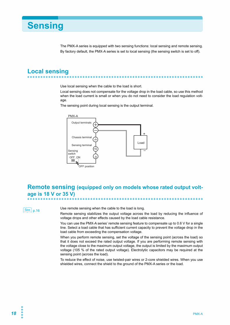
Sensing
The PMX-A series is equipped with two sensing functions: local sensing and remote sensing.By factory default, the PMX-A series is set to local sensing (the sensing switch is set to off).
Local sensing
Use local sensing when the cable to the load is short.Local sensing does not compensate for the voltage drop in the load cable, so use this methodwhen the load current is small or when you do not need to consider the load regulation volt-age.The sensing point during local sensing is the output terminal.
Remote sensing (equipped only on models whose rated output volt-age is 18 V or 35 V)
p.16 Use remote sensing when the cable to the load is long.Remote sensing stabilizes the output voltage across the load by reducing the influence ofvoltage drops and other effects caused by the load cable resistance.You can use the PMX-A series’ remote sensing feature to compensate up to 0.6 V for a singleline. Select a load cable that has sufficient current capacity to prevent the voltage drop in theload cable from exceeding the compensation voltage.When you perform remote sensing, set the voltage of the sensing point (across the load) sothat it does not exceed the rated output voltage. If you are performing remote sensing withthe voltage close to the maximum output voltage, the output is limited by the maximum outputvoltage (105 % of the rated output voltage). Electrolytic capacitors may be required at thesensing point (across the load).To reduce the effect of noise, use twisted-pair wires or 2-core shielded wires. When you useshielded wires, connect the shield to the ground of the PMX-A series or the load.
SensingswitchOFF ON
+
–+S
-S
Output terminals
Chassis terminal
Sensing terminal
PMX-A
Load
OFF position
See
PMX-A 19
Sensing
Prep
arat
ion
1
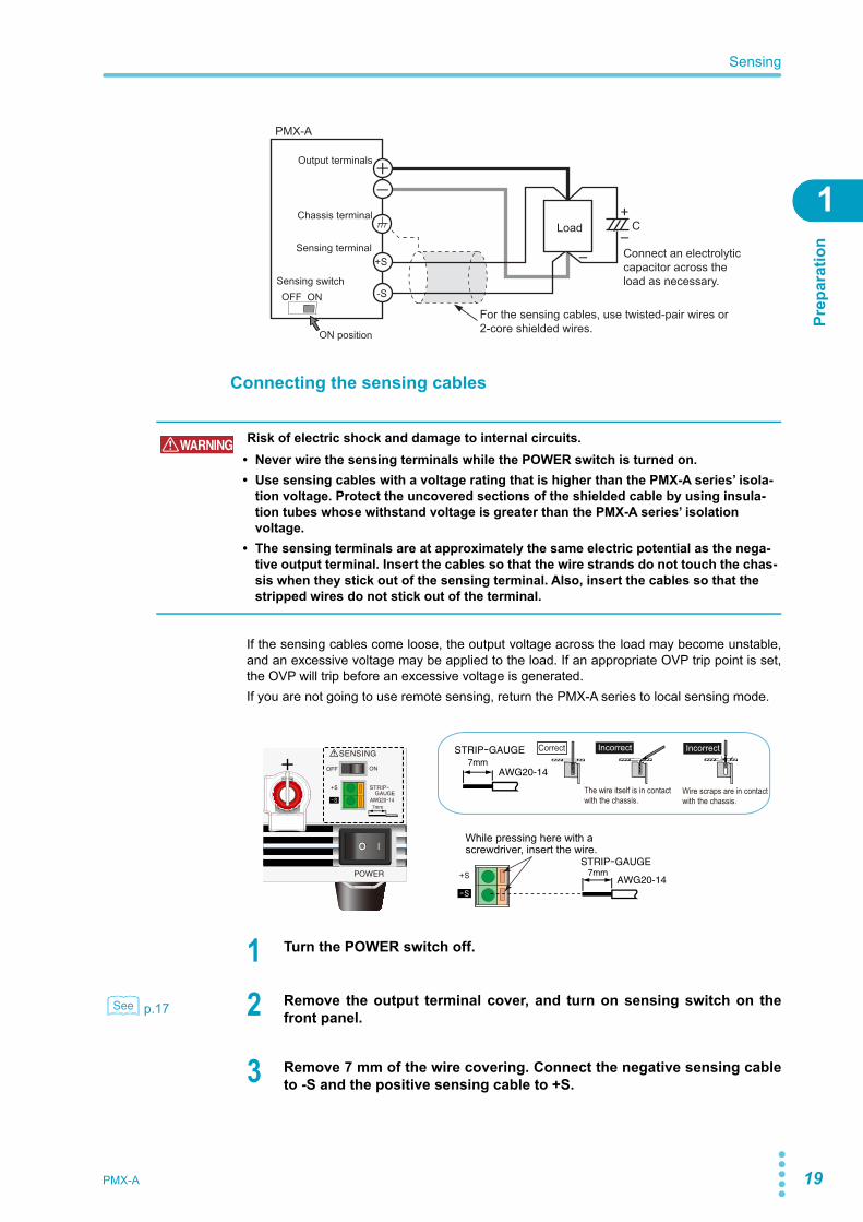
Connecting the sensing cables
If the sensing cables come loose, the output voltage across the load may become unstable,and an excessive voltage may be applied to the load. If an appropriate OVP trip point is set,the OVP will trip before an excessive voltage is generated.If you are not going to use remote sensing, return the PMX-A series to local sensing mode.
1 Turn the POWER switch off.
p.17 2 Remove the output terminal cover, and turn on sensing switch on thefront panel.
3 Remove 7 mm of the wire covering. Connect the negative sensing cableto -S and the positive sensing cable to +S.
++
––
C
+S
-SSensing switchOFF ON
Connect an electrolytic capacitor across the load as necessary.
Output terminals
Chassis terminal
Sensing terminal
PMX-A
Load
For the sensing cables, use twisted-pair wires or2-core shielded wires.ON position
WARNING Risk of electric shock and damage to internal circuits.• Never wire the sensing terminals while the POWER switch is turned on.• Use sensing cables with a voltage rating that is higher than the PMX-A series’ isola-
tion voltage. Protect the uncovered sections of the shielded cable by using insula-tion tubes whose withstand voltage is greater than the PMX-A series’ isolation voltage.
• The sensing terminals are at approximately the same electric potential as the nega-tive output terminal. Insert the cables so that the wire strands do not touch the chas-sis when they stick out of the sensing terminal. Also, insert the cables so that the stripped wires do not stick out of the terminal.
+S
-S
Incorrect IncorrectCorrect
The wire itself is in contact with the chassis.
Wire scraps are in contact with the chassis.
7mmSTRIP-GAUGE
AWG20-14
7mmAWG20-14
STRIP-GAUGE
While pressing here with a screwdriver, insert the wire.
ONOFF
SENSING
AWG20-14
+S
-S
STRIP- GAUGE
7mm
See

20 PMX-A
Sensing
4 Pull out the sensing wires horizontally from the side of the output termi-nal cover, and attach the output terminal cover.
5 Turn the POWER switch on.
If the wiring inductance component is large, the following symptoms may appear.• The PMX-A series oscillates
If the wires used to connect to the load are long, the wiring inductance and capacitancecan cause phase shifting at a level that can not be ignored. This may lead to oscillation.
• The output fluctuatesIf the load current changes drastically in a pulse-shaped pattern, the output voltage maybecome large due to the wiring’s inductance component.
You can reduce the inductance component by twisting the load cables, which stabilizes thevoltage. However, if this does not correct the problem, connect an electrolytic capacitoracross the load.• Electrolytic capacitor to connect across the load
Capacitance: 0.1 µF to a few hundred µFWithstand voltage: At least 120 % of the rated output voltage of the PMX-A series
If you are inserting a mechanical switch between the PMX-A series and theload
If you want to connect and disconnect the load using a mechanical switch that is insertedbetween the PMX-A series and the load, be sure to include switches in the sensing cables asshown in the following figure and turn on and off the load cable and the sensing cables simul-taneously. Before you turn the mechanical switch on or off, be sure to turn the output or thePOWER switch off.
Pull out the sensing wires from here, and attach the output terminal cover.
Load
S
+
–C
+
–
+S
–S
+
–

Basic FunctionsThis chapter describes how to turn the out-put on and off and the basic operations thatyou can perform from the front panel.

22 PMX-A
Measured Value Display and Setting Display
The voltage and current displays have the following two states.• Measured value display• Setting display
In addition to the voltmeter and ammeter, the PMX-A series can display the set OVP or OCP,and the system configuration.
Measured value display
p.26 The present output voltage and output current are displayed. Inthis situation, the SET key is off. You can change the output volt-age and output current in the measured value display.
Setting display
p.49, p.51 Press SET to light its LED and display the present set outputvoltage and output current settings.Press SET again to return to the measured value display.When you recall a preset memory entry, the values stored in thepreset memory entry are displayed on the panel.The display is different when the PMX-A series is being con-trolled externally.
During external voltage control, the voltmeter displays . During external currentcontrol, the ammeter displays .
Overvoltage protection and overcurrent protection setting displayPress OCP•OVP to light its LED and display the present overcur-rent protection and overvoltage protection settings.
System configuration setting displayPress CONFIG to light its LED and display the current systemconfiguration settings.
See
CBA SHIFTALM CLR
SET LOCKCONFIG LOCAL
OUTPUTCV
CC
A
V
REMOTELAN LOCKALARM
PRESET B CA
See
CBA SHIFTALM CLR
SET LOCKCONFIG LOCAL
OUTPUTCV
CC
A
V
REMOTELAN LOCKALARM
PRESET B CA
Lit
CBA SHIFTALM CLR
SET LOCKCONFIG LOCAL
OUTPUTCV
CC
A
V
REMOTELAN LOCKALARM
PRESET B CA
Lit
CBA SHIFTALM CLR
SET LOCKCONFIG LOCAL
OUTPUTCV
CC
A
V
REMOTELAN LOCKALARM
PRESET B CA
Lit

PMX-A 23
Bas
ic F
unct
ions
2
Panel Operations
Measured value display, setting display, and set OVP/OCP displayTurn the VOLTAGE knob to change the voltage. Turn theCURRENT knob to change the current.You can set these values while output is on or off.Press SET to switch to the setting display, and thenchange the output while you view the actual voltage orcurrent settings.
Fine adjustmentYou can change the resolution of the VOLTAGE and CURRENT knobs. Hold down SHIFTwhile you turn the VOLTAGE knob or CURRENT knob to make small changes to the value.When the output is on, the displayed current or voltage may not change even if you turn theVOLTAGE or CURRENT knob. In this situation, the values are being changed at a finer reso-lution than that which is being displayed. The display will change when the amount that youchange the value by reaches the smallest display digit of the set voltage or current.The amount of change varies depending on whether the output is on or off.
Output Operations
The output turns on and off each time that you press OUT-PUT. When output is on, the OUTPUT LED lights. When theoutput is off, the OUTPUT LED turns off.When the output is on, output is generated at the currently setvalues. If you change the settings while the output is on, thechanges are applied to the output.
,p.36, p.53 You can use external control to turn the output on and off.
Output on or off when the PMX-A series turns on
p.42 By factory default, the output is off when the PMX-A series turns on. Using a CONFIG param-eter (CF01: Forc), you can set the PMX-A series so that output is turned on at power-on.
p.28 If you set the PMX-A series so that output is turned on at power-on, be sure to check the OVPtrip point setting before you turn the PMX-A series off.
CURRENT
VOLTAGE
FINE
FINE
CBA SHIFTALM CLR
SET LOCKCONFIG LOCAL
OUTPUTCV
CC
A
V
REMOTELAN LOCKALARM
PRESET B CA
IncreaseDecrease
IncreaseDecrease
MemoWhen you set a value, it is convenient to first use normal resolution to set the value roughly and then switch to fine resolu-tion to set it precisely.
When the output is on1
1 Note that, because smaller digits that are not displayed are also set, the actual setting may bedifferent from the displayed value.
Changes are made at 1/10th the resolution of the minimum digit on the voltmeter or ammeter.
When the output is off Changes are made at increments of 1 in the minimum digit on the voltme-ter or ammeter.
CBA SHIFTALM CLR
SET LOCKCONFIG LOCAL
OUTPUTCV
CC
A
V
REMOTELAN LOCKALARM
PRESET B CA
Lit
Output on
See
See
See
CAUTION If you change the load, it may be damaged if the PMX-A series’ OVP and OCP settings are not correct.

24 PMX-A
CC Power Supply and CC Power Supply
The PMX-A series has features that makes it possible to function as a constant-voltagesource and constant-current source even when the load is changed. The constant-voltagesource operation is referred to as constant-voltage (CV) mode. The constant-current sourceoperation is referred to as constant-current (CC) mode. The operation mode is determined bythe following three values.
• Output voltage setting (Vs)• Output current setting (Is)• Load resistance (RL)
The operation modes are described below.
The above figure shows the PMX-A series operation modes. The load resistance is denotedas RL. The resistance, which is denoted as Rc, is calculated from the set voltage and current(Rc = Vs/Is). The power supply is designed so that it operates in CV mode in area and CCmode in area . The boundary is the line defined by RL = Rc. This line represents the load atwhich the output voltage and the set voltage are equal and the output current and the set cur-rent are equal. If load resistance RL is greater than resistance Rc, the operating point is inarea , and the PMX-A series operates in CV mode (point p). In this case, the set current Isequals the current limit.When the PMX-A series is operating in CV mode, the output voltage is maintained at the setvoltage. Output current I is determined by the equation I = Vs/RL and is a current that is lessthan current limit Is. The actual current that flows is not necessarily equal to the specifiedvalue.For loads in which transient peak current flows, current limit Is must be set higher than thepeak value.
Conversely, if load resistance RL is less than resistance Rc, the operating point is in area ,and the PMX-A series operates in CC mode (point q). In this case, set voltage Vs equals thevoltage limit.When the PMX-A series is operating in CC mode, the output current is maintained at the setcurrent. Output voltage V is determined by the equation V = Is x RL and is a voltage that isless than voltage limit Vs. The actual voltage that is applied is not necessarily equal to thespecified value.
Crossover pointThe PMX-A series switches automatically between CV mode and CC mode according to thechanges in the load. A crossover point is the point at which the mode switches.For example, when operating in CV mode, if the load changes and the output current reachesthe current limit, the PMX-A series automatically switches to CC mode to protect the load.Likewise, when operating in CC mode, if the output voltage reaches the voltage limit, thePMX-A series switches to CV mode.
0 ImaxIs
Vs
Vmax
Output current Iout
Crossover point
A = CV mode area B = CC mode area
Vs = Set voltageIs = Set currentRc = Vs/Is (Ohm’s Law)RL = Load resistanceVmax = Maximum settable voltageImax = Maximum settable current
RL=RcRL>Rc
RL<Rc
p
q
A
B
Out
put v
olta
ge V
out
AB
A
B

PMX-A 25
CC Power Supply and CC Power Supply
Bas
ic F
unct
ions
2
CV mode and CC mode operation exampleThis section uses a power supply (PMX35-3A) with a rated output voltage of 35 V and a ratedoutput current of 3 A as an example.A load resistance (RL) of 60 Ω is connected to the output terminals of the power supply. Theoutput voltage and output current are set to 20 V and 0.5 A, respectively. In this case, Rc = 20V/0.5 A = 40 Ω. Because 60 Ω is greater than 40 Ω (RL > Rc), the power supply operates inCV mode. When you want to increase the voltage in CV mode, you can increase the voltageup to the voltage defined by the following equation: Vs = Is x RL. Substituting the values, weobtain Vs = 0.5 A x 60 Ω = 30 V. If you try to increase the voltage above this point, the cross-over point is reached, and the power supply automatically switches to CC mode. To maintainoperations in CV mode, increase the current limit.Next, a load resistance (RL) of 25 Ω is connected to the output terminals of the power supply.The output voltage and output current are set to 20 V and 0.5 A, respectively. In this case, Rc= 20 V/0.5 A = 40 Ω. Because 40 Ω is greater than 25 Ω (RL < Rc), the power supply operatesin CC mode. When you want to increase the current in CC mode, you can increase the cur-rent up to the current defined by the following equation: Is = Vs/RL. Substituting the values,we obtain Is = 20 V/25 Ω = 0.8 A. If you try to increase the current above this point, the cross-over point is reached, and the power supply automatically switches to CV mode. To maintainoperations in CC mode, increase the voltage limit.

26 PMX-A
Using the PMX-A Series as a CV or CC Power Supply
When the PMX-A series is used as a constant-voltage power supply, the set current is thelimit to the current that can flow through the load.When the PMX-A series is used as a constant-current power supply, the set voltage is thelimit to the voltage that can be applied to the load.
If the specified limit is reached, the PMX-A series automatically switches its operation mode.When the PMX-A series switches its operation mode, the lit LED in the display area (CV LEDor CC LED) changes to indicate the switch.
1 Turn the POWER switch off.
p.17 2 Connect the load to the output terminals.
3 Turn the POWER switch on.If the OUTPUT LED in the display area is lit, press OUTPUT to turn the output off.
4 Press SET to change to the setting display.The SET key lights.
p.23 5 Turn the VOLTAGE knob to set the voltage.
6 Turn the CURRENT knob to set the current.
7 Press OUTPUT to turn output on.The SET key turns off, and the OUTPUT LED in the display area lights. The voltageand current are generated from the output terminals. When the PMX-A series is oper-ating as a constant-voltage power supply, the CV LED in the display area lights. Whenthe PMX-A series is operating as a constant-current power supply, the CC LED lights.
Even when the output is on, you can set the voltage and current by carrying out step 5 andstep 6 while checking the actual output voltage or current.
p.36 You can use the CONFIG settings to set the output-on startup state (CF08: prioritize CC orCV).Set this according to the operation mode that you are using. You can prevent overshootfrom occurring when the output is turned on by prioritizing CV when using the PMX-A seriesas a constant-voltage power supply and by prioritizing CC when using the PMX-A series as aconstant-current power supply.If external control is in progress, you cannot set the output-on startup state (prioritize CC/ pri-oritize CV).
See
See
PMX18-2A 0 V to 18.9 V PMX70-1A 0 V to 73.5 V
PMX18-5A 0 V to 18.9 V PMX110-06A 0 V to 115.5 V
PMX35-1A 0 V to 36.75 V PMX250-0.25A 0 V to 262.5 V
PMX35-3A 0 V to 36.75 V PMX350-0.2A 0 V to 367.5 V
PMX500-0.1A 0 V to 525.0 V
PMX18-2A 0 A to 2.1 A PMX70-1A 0 A to 1.05 A
PMX18-5A 0 A to 5.25 A PMX110-06A 0 A to 0.63 A
PMX35-1A 0 A to 1.05 A PMX250-0.25A 0 A to 0.262 A
PMX35-3A 0 A to 3.15 A PMX350-0.2A 0 A to 0.21 A
PMX500-0.1A 0 A to 0.105 A
See

PMX-A 27
Bas
ic F
unct
ions
2
Protection Functions and Alarms
The PMX-A series is equipped with the following protection functions.• Overvoltage protection (OVP)• Overcurrent protection (OCP)• Overheat protection (OHP)
Alarm occurrence and clearing alarms
Alarm occurrenceWhen a protection function is activated, the PMX-Aseries behaves as follows.
•Output Off•The ALARM LED in the front panel display area lights toindicate that an alarm has occurred. The voltmeter indi-cates the cause of the alarm.
•The alarm signal is generated from pin 13 of the J1 connector.
Clearing alarms
Press ALM CLR (SHIFT + SET) or turn off the POWER switch. Fix the problem that causedthe alarm, and turn the POWER switch back on.
If an alarm still occurs even after you have corrected all the causes of alarms, the PMX-Aseries may be malfunctioning. Stop using it immediately, and contact your Kikusui agent ordistributor.
For an explanation of the problems that cause the alarms, see the explanation of each pro-tection function.
Alarm signalThe alarm signal is isolated from other ter-minals through an open collector photo-coupler.The CV, CC, output-on, and power-on sig-nals share a common ground.
CBA SHIFTALM CLR
SET CONFIG LOCAL
OUTPUTCV
CC
A
V
REMOTELAN LOCKALARM
PRESET B CA
Lit
OHP alarm indication
13
25
J1 connector
ALM STATUS
STATUS COM
PMX-A
Maximum voltage: 30 VMaximum current: 8 mA

28 PMX-A
Protection Functions and Alarms
Protection function activation
Overvoltage protection (OVP) and overcurrent protection (OCP)The overvoltage protection function is activated when the output terminal voltage exceeds theset voltage (OVP trip point).
The overcurrent protection function is activated when the output current exceeds the set cur-rent (OCP trip point).
The OVP and OCP trip points need to be set to appropriate values. Immediately after youpurchase the PMX-A series or immediately after a load is changed, set the OVP and OCP trippoints to values that are appropriate for the load.
Setting the OVP and OCP trip pointsThe PMX-A series’ OVP operates according tothe output terminal voltage. If you want to acti-vate the protection function according to the volt-age across the load, take the voltage drop in theload cable into consideration when you set theOVP trip point.
1 Press OVP • OCP.The OCP • OVP key lights, and the OVP trip point and OCP trip point are displayed inthe display area.
2 While viewing the panel display, turn the VOLTAGE knob to set the OVPtrip point or the CURRENT knob to set the OCP trip point.
p.23 Hold down SHIFT while you turn the VOLTAGE knob or CURRENT knob to make smallchanges to the value.OVP setting range: 10 % to 110 % of the rated output voltage
OCP setting range: 10 % to 110 % of the rated output current
3 Press OCP • OVP to finalize the setting.The OCP • OVP key turns off, and the PMX-A series returns to the measured value dis-play.
CURRENT
VOLTAGE
FINE
FINE
CBA SHIFTALM CLR
SET LOCKCONFIG LOCAL
OUTPUTCV
CC
A
V
REMOTELAN LOCKALARM
PRESET B CA
Lit
OCP trip point
OVP trip point
OVP and OCP trip point displays
See
OVP setting OCP settingPMX18-2A 1.8 V to 19.8 V 0.2 A to 2.2 APMX18-5A 1.8 V to 19.8 V 0.5 A to 5.5 APMX35-1A 3.5 V to 38.5 V 0.1 A to 1.1 APMX35-3A 3.5 V to 38.5 V 0.3 A to 3.3 APMX70-1A 7.0 V to 77.0 V 0.1 A to 1.1 APMX110-0.6A 11.0 V to 121.0 V 0.06 A to 0.66 APMX250-0.25A 25.0 V to 275.0 V 0.025 A to 0.275 APMX350-0.2A 35.0 V to 385.0 V 0.02 A to 0.22 APMX500-0.1A 50.0 V to 550.0 V 0.01 A to 0.11 A

PMX-A 29
Protection Functions and Alarms
Bas
ic F
unct
ions
2
Checking OVP and OCP operation
To check the operation of the OVP function, carry out the procedure below.
1 Check that the OUTPUT LED in the display area is turned off.
2 Set the output voltage to a value lower than the OVP trip point.
3 Press OUTPUT to turn output on.The OUTPUT LED lights.
4 Slowly turn the VOLTAGE knob clockwise.When the output voltage exceeds the OVP trip point, the front panel display area’sALARM LED lights to indicate that the OVP function has been activated.
5 Check that output has turned off.
6 Turn the POWER switch off.
To check the operation of the OCP function, carry out the procedure below.
1 Short the output terminals.
2 Turn the POWER switch on.
3 Check that the OUTPUT LED in the display area is turned off.
4 Set the output current to a value lower than the OCP trip point.
5 Press OUTPUT to turn output on.The OUTPUT LED lights.
6 Slowly turn the CURRENT knob clockwise.When the output current exceeds the OCP trip point, the front panel display area’sALARM LED lights to indicate that the OCP function has been activated.
7 Check that output has turned off.
If you do not change the output settings, the OVP or OCP function will be activated again.
CBA SHIFTALM CLR
SET LOCKCONFIG LOCAL
OUTPUTCV
CC
A
V
REMOTELAN LOCKALARM
PRESET B CA
LitOVP activation alarm indication
CBA SHIFTALM CLR
SET LOCKCONFIG LOCAL
OUTPUTCV
CC
A
V
REMOTELAN LOCKALARM
PRESET B CA
LitOCP activation alarm indication

30 PMX-A
Protection Functions and Alarms
Overheat protection (OHP)The overheat protection function is activated when the PMX-A series’ internal temperaturerises to an abnormal level.
• When the PMX-A series is used in an environment that exceeds its operating ambienttemperature range (0 °C to +40 °C).
• When the PMX-A series is used with its air inlet or outlet port blocked.• When the fan motor has stopped.
If you do not fix the problem that caused the OHP to be activated, OHP will be activated againeven if you turn the POWER switch off and on.

PMX-A 31
Bas
ic F
unct
ions
2
CONFIG Settings
Use the CONFIG settings to set the PMX-A series’ system configuration. You can set anddisplay the following parameters in the CONFIG settings.
In the “Note” column, “A” indicates a parameter that is applied when the PMX-A series exits from CON-FIG settings, “B” indicates a parameter that is applied when the PMX-A series is turned on, and “C” indi-cates a parameter that is applied when CF34 is executed.
Display switching
Parameter number
Setting or display description Note
SYSTEM CF00 Resets the panel settings A
CF01 Power-on output status parameter B
CF02 Memory content display parameter A
CF03 Key lock parameter A
CF041 2
1 This parameter affects the PMX-A series when the panel settings are reset (CF00).2 The item can be configured only when the output is off.
CC control using an external voltage or external resistance A
CF051 2 CV control using an external voltage or external resistance A
CF061 2 External control parameter for turning output on and off A
CF072 External control logic parameter for turning output on and off A
CF083
3 This parameter cannot be set if external control is in progress.
Output-on startup state parameter A
INTERFACE CF20 Remote interface parameter B
CF21 SCPI communication error display parameter A
LAN CF30 DHCP parameter B or C
CF31 AUTO IP address parameter B or C
CF32 MANUAL IP address parameter B or C
CF33 Resets the LAN interface settings (LCI) A
CF34 Restarts the LAN interface (REBOOT) A
CF35 IP address display (1) —
CF36 IP address display (2) —
CF37 IP address display (3) —
CF38 IP address display (4) —
CF39 MAC address display (1) and (2) —
CF40 MAC address display (3) and (4) —
CF41 MAC address display (5) and (6) —
USB CF50 VID (vendor ID) display —
CF51 PID (product ID) display —
CBA SHIFTALM CLR
SET LOCKCONFIG LOCAL
OUTPUTCV
CC
A
V
REMOTELAN LOCKALARM
PRESET B CA
LitBlinking
Parameter number CF (CONFIG) + a two-digit number
Value display
CONFIG setting and display examples

32 PMX-A
CONFIG Settings
Setting and viewing CONFIG parameters
CF00, CF33, and CF34 are used to execute operations. CF35 to CF41, CF50, and CF51 areused to display the status of the PMX-A series. You cannot set the values of any of theseCONFIG parameters.For CF00, CF33, and CF34, the SET key is used to apply the settings. The settings have notyet been applied when the SET key is blinking.
CONFIG key
CONFIG key
CONFIG key
CONFIG key
CURRENT
VOLTAGE
FINE
FINE
CBA SHIFTALM CLR
SET LOCKCONFIG LOCAL
OUTPUTCV
CC
A
V
REMOTELAN LOCKALARM
PRESET B CA
Measured value display
System settings
Interface settings
Interface-specific settings LAN(CF20: LAn)
USB(CF20: uSb)
RS232C(CF20: 232)
CF00CF01
CF08
CF20CF21
CF30CF31
CF41
CF50CF51
VOLTAGEknob
VOLTAGEknob
VOLTAGE knob
VOLTAGE knobSelect the parameter number.
CONFIG keySelect the parameter number.
CURRENT knobChange the parameter value.

PMX-A 33
CONFIG Settings
Bas
ic F
unct
ions
2
Specifying the CONFIG settings(Excluding resetting the settings, resetting the LAN interface settings, and restarting the LAN interface)
1 Press CONFIG.The CONFIG key lights and the SET key blinks. The voltmeter displays the parameternumber (CF00) . The ammeter displays the corresponding setting(rST) .
2 Press CONFIG or turn the VOLTAGE knob to select the number of theparameter that you want to set.When you press CONFIG, the PMX-A series switches between the parameter num-bers in the following order. The displayed parameter numbers vary depending on theinterface that you select.
LAN: CF00 → CF20 → CF30 → measured value displayUSB: CF00 → CF20 → CF50 → measured value displayRS232C: CF00 → CF20 → measured value display
When you turn the VOLTAGE knob, the PMX-A switches between the parameter num-bers. The parameter numbers that are displayed when you turn the VOLTAGE knobare those within the ranges defined by the parameter numbers that pressing the CON-FIG key switches between.
3 Turn the CURRENT knob to change the value of the parameter.
p.31 There are parameters whose values are applied immediately, those whose values areapplied after the power is turned off and then back on, and those whose values areapplied when CF33 or CF34 is executed.
4 To specify or display other parameters, repeat step 2 and step 3.To stop specifying CONFIG settings, proceed to step 5.
5 Hold down CONFIG until the measured value display appears, orLOCAL.The PMX-A series exits from CONFIG settings.If you changed a parameter with the “Note” column indicated as “A” in the CONFIGlist on page 31 , the change is applied.
You can also press SET to exit from CONFIG settings.
Resetting the settings (CF00)
1 Press CONFIG once (CF00).The CONFIG key lights and the SET key blinks.
The voltmeter displays the parameter number (CF00) . The ammeter displaysthe corresponding setting (rST) .
2 Press SET, which is blinking, again.The settings are applied. The measured value display appears.While the parameter number and the setting are blinking, no new settings will beapplied until you press SET.
MemoPress CONFIG or turn the VOLTAGE knob to switch between the parameter numbers. These two methods switch between the parameter numbers differently.
See
MemoYou can cancel the set-tings using CONFIG.

34 PMX-A
CONFIG Settings
Resetting the LAN interface settings (CF33) and restarting (CF34)
1 Press CONFIG twice to select the LAN interface , and then press itagain.The CONFIG key lights.
The voltmeter displays the parameter number (CF30) . The ammeter displaysthe corresponding setting (on) .
2 Turn the VOLTAGE knob to select the number of the parameter you wantto set.If you are resetting the LAN interface settings, the voltmeter displays “CF33 ,”the ammeter displays “LCi ,” and the SET key blinks.If you are restarting, the voltmeter displays “CF34 ,” the ammeter displays“boot ,” and the SET key blinks.
3 Press SET.The CONFIG key turns off. The SET key and the displayed settings blink.
4 Press SET again.The settings are applied.The SET key and displayed settings stop blinking (remain lit), and the OVP • OCP andCONFIG keys light.After approximately 4 to 5 seconds, the measured value display appears, and the set-tings are applied.
MemoIf you want to cancel the settings, press CONFIG before you press SET.
CBA SHIFTALM CLR
SET LOCKCONFIG LOCAL
OUTPUTCV
CC
A
V
REMOTELAN LOCKALARM
PRESET B CA
Lit CBA SHIFTALM CLR
SET LOCKCONFIG LOCAL
OUTPUTCV
CC
A
V
REMOTELAN LOCKALARM
PRESET B CA
Lit
Display exam-ple of CF34 being applied
Display example of CF33 being

PMX-A 35
CONFIG Settings
Bas
ic F
unct
ions
2
CONFIG parameter details
The CONFIG parameters are explained in detail below.
CF00 Resets the panel settings
Communication Inter-face Manual
Resets the panel settings. The following settings will be reset. When the settings are reset,the PMX-A series’ settings take on the same values as they do when an *RST command isreceived.
• Output voltage • Output on/off at power-on• Output current • Constant current control using an external volt-
age or external resistance (CF04)• Overvoltage protection • Constant voltage control using an external volt-
age or external resistance (CF05)• Overcurrent protection • External control for turning output on and off
(CF06)
CF01 Power-on output status parameter
p.11 Sets the output condition that the PMX-A series will be in when the power is turned on. Whenyou are using an external contact to turn the output off, this parameter is invalid.This parameter is applied when you turn the POWER switch off and on.
CF02 Memory content display parameter
p.40 Sets whether to display the saved contents in the preset memory before recalling them.You can use this CONFIG parameter if you forget what settings have been saved or if youwant to view the saved settings.
CF03 Key lock parameter
p.41 The key lock feature locks the panel. Select from the following three values.
See
Display Description
rSt Resets the panel settings
See
Value Description
SAFE The PMX-A series starts with the output turned off (factory default set-ting).
Auto The PMX-A series starts with the output set to the condition that was used immediately before the POWER switch was turned off.
ForC The PMX-A series starts with the output turned on.
See
Value Description
oFF The saved contents of preset memory will be recalled without display-ing them.
on The saved contents of preset memory will be displayed and then recalled after confirmation (factory default setting).
See
Value Description
Loc1 Only the OUTPUT key and recalling of settings using memory keys A, B, and C are allowed.
Loc2 Only the OUTPUT key can be used.
Loc3 All keys and rotary operations are disabled (factory default setting).

36 PMX-A
CONFIG Settings
CF04 CC control using an external voltage or external resistance
p.35, p.40, p.51
Selects whether the output current will be controlled by an external voltage or external resis-tance (the J1 connector). This is set to “nonE” when the panel settings are reset (CF00).The item can be configured only when the output is off.
CF05 CV control using an external voltage or external resistance
p.49 Selects whether the output voltage will be controlled by an external voltage or external resis-tance (the J1 connector). This is set to “nonE” when the panel settings are reset (CF00).The item can be configured only when the output is off.
CF06 External control parameter for turning output on and off
p.53 Selects whether an external contact (the J1 connector) will be used to turn output on and off.This is set to “oFF” when the panel settings are reset (CF00).The item can be configured only when the output is off.
CF07 External control logic parameter for turning output on and off
p.53 Sets the logic that is used when an external contact (the J1 connector) is used to turn outputon and off. The item can be configured only when the output is off.
CF08 Output-on startup state parameter
p.26 Sets the operation mode to be prioritized when the output is turned on.This parameter cannot be set if external control is in progress.
See
Value Description
nonE CC control is not performed (factory default setting).
VoLt CC control using external voltage will be performed.
rES CC control using external resistance will be performed.
See
Value Description
nonE CV control is not performed (factory default setting).
VoLt CV control using external voltage will be performed.
rES CV control using external resistance will be performed.
See
Value Description
oFF External control is not performed (factory default setting).
on External control is performed.
See
Value Description
Lo The output is turned on with a low signal (0 V to 0.5 V) or short circuit (factory default setting).
Hi The output is turned on with a high signal (4.5 V to 5 V) or open circuit.
See
Value Parameter description
CC CC (constant current) is prioritized.
CV CV (constant voltage) is prioritized (factory default setting).

PMX-A 37
CONFIG Settings
Bas
ic F
unct
ions
2
CF20 Remote interface parameterSelects the remote interface that you want to use.This parameter is applied when you turn the POWER switch off and on.
CF21 SCPI communication error display parameterSelects whether to display communication errors. The errors are only displayed when you areusing the SCPI language.
CF30 DHCP parameterSelects whether or not to obtain an IP address from a DHCP server. If you are using a fixedIP address, set this to oFF.This parameter is applied when you turn the POWER switch off and on or when you restartthe LAN interface (CF34).
CF31 AUTO IP address parameterSet whether to automatically attain an IP address when you are not using or can not use aDHCP server. The address that is assigned by the AUTO IP function is 169.254.x.x (where xis a number between 0 and 254). If you are using a fixed IP address, set this to oFF. Thisparameter is applied when you turn the POWER switch off and on or when you restart theLAN interface (CF34).
CF32 MANUAL IP address parameterSet whether to manually specify an IP address when you are not using or can not use aDHCP server. If you are using a fixed IP address, set this to on.This parameter is applied when you turn the POWER switch off and on or when you restartthe LAN interface (CF34).
Value Description
LAn LAN will be used (factory default setting).
uSb USB will be used.
232 RS232C is used.
Value Description
oFF SCPI communication errors are not displayed (factory default setting).
on SCPI communication errors are displayed.
Value Description
oFF A DHCP server is not used.
on A DHCP server is used (factory default setting).
Value Description
oFF The AUTO IP function will not be used.
on The AUTO IP function will be used (factory default setting).
Value Description
oFF The MANUAL IP function will not be used (factory default setting).
on The MANUAL IP function will be used.

38 PMX-A
CONFIG Settings
CF33Resetting the LAN interface settings (LCI)
p.42 This parameter resets the LAN interface settings to their factory default settings. You can usethis if you forget the security password or IP address.
CF34 Restarts the LAN interface (REBOOT)This parameter restarts the LAN interface. The LAN interface settings that you have specifieddo not change.
CF35 to CF38 IP address displayThese parameters display the set IP addresses. These parameters are only displayed whenyou are using the LAN interface.The IP addresses are just displayed; they cannot be set from the panel. To set a fixed IPaddress, access the PMX-A series through a Web browser. When you access the PMX-Aseries through a Web browser, do so under conditions in which a DHCP server or AUTO IPcan be used.For details on the Web interface, see the Communication Interface Manual.
CF39 to CF41 MAC address displayThese parameters display the set MAC addresses.The MAC addresses are just displayed; they cannot be set from the panel.MAC addresses are set to 00.0F.CE.xx.xx.xx (where x is a hexadecimal number between 0and F).
CF50 Vendor ID (VID) displayThis displays the USB vendor ID.
See
Display Description
LCi The LAN interface settings will be reset to their factory default settings.
Display Description
boot The LAN interface settings are saved, and the interface is restarted.
Parameter number Display Description
CF35 0 to 255 Displays the first IP address number
CF36 0 to 255 Displays the second IP address number
CF37 0 to 255 Displays the third IP address number
CF38 0 to 255 Displays the fourth IP address number
Parameter number Display Description
CF39 00.0F Displays the first and second MAC address numbers
CF40 CE.xx Displays the third and fourth MAC address numbers
CF41 xx.xx Displays the fifth and sixth MAC address numbers
CV
CC
A
VCV
CC
A
VCV
CC
A
VDisplay example of the MAC address “00.0F.CE.11.22.33:"
CF39: 00.0F CF41: 22.33CF40: CE.11
Display Description
0b3E 0x0B3E

PMX-A 39
Preset Memory Function
Bas
ic F
unct
ions
2
CF51 Product ID displayThis displays the USB product ID.
Preset Memory Function
The PMX-A series has three preset memory entries (A, B, and C) where you can save combi-nations of voltage and current settings. Saved settings can be recalled from the preset mem-ory when needed. To select the preset memory entry to save to or recall from, hold downSHIFT and press A, B, or C.Recalling is executed immediately when a preset memory entry is specified. If you keepspecifying a preset memory entry by holding down the keys, the present settings are saved tothe entry area.
Saving settings to preset memory
1 Press SET.The SET key lights, and the present voltage and current settings are displayed on thepanel.
2 While viewing the values displayed on the panel, turn the VOLTAGEknob to set the preset memory voltage and turn the CURRENT knob toset the preset memory current.
3 Press SHIFT+the memory key that corresponds to the memory entry thatyou want to save the settings to (A, B, or C). Hold the keys down untilthe corresponding PRESET LED turns on.The PRESET A, PRESET B, or PRESET C LED in the display area—whichever one cor-responds to the memory entry that you selected—lights to indicate that the presetmemory entry has been saved.
By following step 3, you can save preset memory entries when the output is on and the mea-sured value display is being shown (the SET key is off). After you save a preset memoryentry, press SET to view the preset memory.
Display Description
1029 0x1029
When you save settings to a preset memory entry, release the memory key first.If you release SHIFT first, the operation indicated in black characters above the key will be activated.

40 PMX-A
Preset Memory Function
Recalling preset memory entries
You can recall memory entries from the measured value display (when the SET key is off)and from the setting display (when the SET key is lit).On the measured value display, the measured values continue to be displayed even after therecalling of the preset memory entry is complete.On the setting display, the settings recalled from the preset memory are displayed.If the output is on, the values in the preset memory entry are applied to the output themoment that the preset memory entry is recalled (the moment that the settings are applied).
p.35 There are two methods to recall a preset memory entry. One method is to display the savedcontents for confirmation and then recall (CF02: on). The other is to recall immediately with-out displaying the contents (CF02: oFF).
Displaying the saved contents for confirmation and then recalling
1 While holding down SHIFT, press the appropriate memory key (A, B, orC).The SET key, the PRESET LED of the memory to recall from (A, B, or C), and the con-tents (voltage and current) of the recalled preset memory that are shown in the displayarea blink. If you press another memory key while holding down SHIFT, the contents ofthe corresponding memory appear blinking.
2 Check the displayed settings, and then press SET.The LED that corresponds to the preset memory entry that you have recalled (PRESETA, B, or C) lights.
Recalling without displaying the saved contents
1 Use the CONFIG settings to set the PMX-A series to hide the saved con-tents of preset memory entries (CF02: oFF).
2 While holding down SHIFT, press the appropriate memory key (A, B, orC).The LED that corresponds to the preset memory entry that you have recalled (PRESETA, B, or C) lights.
See
If you hold down SHIFT+the memory key (A, B, or C) that corresponds to the preset memory entry that you want to recall from, the preset values in use will be saved to the preset mem-ory entry instead.
MemoPress LOCAL to cancel recalling.
MemoThe one-step recall fea-ture is convenient when you know the contents that have been saved to the memory.

PMX-A 41
Bas
ic F
unct
ions
2
Locking Panel Controls (Key lock)
The PMX-A series’ key lock function prevents you from acci-dentally changing the settings.
p.35 The following three key lock modes are available. Use CONFIG parameter CF03 to set themode.
• Key lock 1 (Loc1): Lock all keys except the OUTPUT and memory A, B, and C keys.• Key lock 2 (Loc2): Locks all keys except the OUTPUT key.• Key lock 3 (Loc3): Lock all keys and the rotary knob.
1 Configure all the settings, such as the output voltage and output cur-rent, as necessary.
2 Hold down LOCK until the LOCK LED in the display area lights.When the LOCK LED lights, the keys are locked.
To unlock the keys, hold down LOCK again until the LOCK LED turns off.
Remote Control
You can remotely control the product from a PC using SCPI commands through the RS232C, LAN, or USB interface. Moreover, with the LAN interface, you can use the Web browser inter-face to remotely control the product from a virtual front panel. For details on remote control, see the Communication Interface Manual.
Switching from Remote Mode to Local ModeTo switch the PMX-A series to local mode from the front panel,press LOCAL.
CBA SHIFTALM CLR
SET LOCKCONFIG LOCAL
OUTPUTCV
CC
A
V
REMOTELAN LOCKALARM
PRESET B CA
Lit
See
CBA SHIFTALM CLR
OVP•OCPSET LOCKCONFIG LOCAL
OUTPUTCV
CC
A
V
REMOTELAN LOCKALARM
PRESET B CA

42 PMX-A
Factory Default Settings (Initialization)
If you hold down LOCK and LOCAL and turn the POWER switch on, the PMX-A series will bereset to the factory default settings.The factory default settings are shown below.
Basic settings
CONFIG settings
Basic item Description
Output voltage 0 V
Output current Maximum settable current
OVP (overvoltage protection) 110 % of the rated output voltage
OCP (overcurrent protection) 110 % of the rated output current
Preset memory valules A/ B/ C Voltage: 0 V, Current: Maximum settable current
Parameter number CONFIG parameter Description
CF01 Power-on output status parameter SAFE (the PMX-A series starts with the output turned off)
CF02 Memory content display parameter ON (displayed)
CF03 Key lock parameter LOC3 (all keys and the rotary knob are locked)
CF04 CC control using an external voltage or external resistance
NONE (disabled)
CF05 CV control using an external voltage or external resistance
NONE (disabled)
CF06 External control parameter for turning output on and off
OFF (disabled)
CF07 External control logic parameter for turning output on and off
LO (a low signal turns output on)1
1 LOW: 0 V to 0.5 V, or a short circuit
CF08 Output-on startup state parameter CV (CV is prioritized)
CF20 Remote interface parameter LAN
CF21 SCPI communication error display parame-ter
OFF (not displayed)
CF30 DHCP parameter ON (a server is used)
CF31 AUTO IP address parameter ON (the AUTO IP function is used)
CF32 MANUAL IP address parameter OFF (the MANUAL IP address function is not used)

External ControlThis chapter explains external control andexternal monitoring using the J1 connector.

44 PMX-A
General Description
You can use the J1 connector on the rear panel of the PMX-A series to perform the followingtypes of external control.• Output voltage control
Control using an external voltage or external resistance• Output current control
Control using an external voltage or external resistance• Turning output on and off using an external contact• Monitoring operation modes
About the J1 Connector
The PMX70-1A, PMX110-0.6A, PMX250-0.25A, PMX350-0.2A, andPMX500-0.1A are factory shipped with a cover is attached to the J1connector. If it is damaged or lost, contact your Kikusui agent or distributor.
The J1 connector for external control is the D-sub 25-pin connector on the rear panel.The cable is not supplied with the product. It must be obtained separately.
• Connector on the rear panelD-sub 25-pin female connectorMade by TE Connectivity (former AMP)
• Compatible connector (plug)D-sub 25-pin male plug, with fix screw
To avoid malfunctions caused by noise, use shielded D-sub 25-pin connectors and a cablethat is 3 m or less in length.
p. 87 A connector kit option, OP01-PMX (749809-9 DB25), is available for connecting to the J1connector. The connector kit is constructed of connector parts made by TE Connectivity (for-mer AMP). For information about how to use these components, see the TE Connectivity (for-mer AMP) catalogs.For information about how to obtain these tools or replacement parts, contact your Kikusuiagent or distributor.
J1 connector cover
WARNING Risk of electric shock.For safety reasons, Be sure to attach the cover when you are not using the J1 connec-tor.
AC INPUT 50
IF THIS COLUMN IS BLANK,THE UNIT IS WIRED IN 100V
LINEVOLTAGE
STANDARD 100V
120V
200V
230V
SETTINGSUPPLY
J1 connectorD-sub 25 pin female
#4-40UNCinch screw
See
Connector type 5747461-3 [ made by TE Connectivity (former AMP) ]
Plug type 745211-7 [ made by TE Connectivity (former AMP) ]
Wire diameter AWG26 to AWG22
Manual pressure welding tool
Handle assembly 58074-1 [ made by TE Connectivity (former AMP) ]Head assembly 58063-2 [ made by TE Connectivity (former AMP) ]
Insertion/extraction tool 91232-1 [ made by TE Connectivity (former AMP) ] or equivalent

PMX-A 45
About the J1 Connector
Exte
rnal
Con
trol
3
J1 connector pin arrangement
12345678910111213
141516171819202122232425
J1
Pin number positions when you are facing the rear panel
PinNo. Signal name Description
1 VMON Output voltage monitor; outputs 0 V to 10 V for 0 % to 100 % of the rated output voltage.
2 IMON Output current monitor; outputs 0 V to 10 V for 0 % to 100 % of the rated output current.
3 ACOM External signal common for pins 1, 2, 4, and 14. 1
4 EXT-V CV CONT Output voltage control using external voltage; receives 0 V to 10 V to output 0 % to 100 % of the rated voltage.
5 ACOM External signal common for pins 1, 2, 4, and 14. 1
6 EXT-R CV CONT Output voltage control using external resistance; uses 0 Ω to 10 kΩ to output 0 % to 100 % of the rated voltage.
7 EXT-R CV CONT COM Common for output voltage control using external resistance.
8 N.C. Not connected.
9 N.C. Not connected.
10 N.C. Not connected.
11 CV STATUS On when the PMX-A series is in CV mode (open-collector output from a photocoupler).2
12 CC STATUS On when the PMX-A series is in CC mode (open-collector output from a photocoupler). 2
13 ALM STATUS On when a protection function (OVP, OCP, or OHP) is activated (open-collector output from a pho-tocoupler).2
14 EXT-V CC CONT Output current control using external voltage; receives 0 V to 10 V to output 0 % to 100 % of the rated current.
15 ACOM External signal common for pins 1, 2, 4, and 14.1
16 EXT-R CC CONT Output current control using external resistance; uses 0 Ω to 10 kΩ to output 0 % to 100 % of the rated current.
17 EXT-R CC CONT COM Common for output current control using external resistance.
18 OUT ON/OFF CONT Output on/off control using external contact input.
19 DCOM External signal common for pin 18.1
20 N.C. Not connected.
21 N.C. Not connected.
22 N.C. Not connected.
23 OUT ON STATUS On when output is on (output through an open-collector photocoupler).2
24 PWR ON STATUS On when the power is on (output through an open-collector photocoupler).2
25 STATUS COM Status signal common for pins 11, 12, 13, 23, and 24.
1 During remote sensing, this is the negative electrode (-S) of sensing input. When remote sensing is not being performed, this isconnected to the negative output.
2 Open collector output: maximum voltage 30 V, maximum current (sink) 8 mA;the status common is floating (isolation voltage or less), it is isolated from the control circuit.

46 PMX-A
Output Terminal Insulation
The cable and load that are connected to the output terminal (including the sensing terminal)must have an insulation capacity that is greater than or equal to the isolation voltage of thePMX-A series with respect to the chassis. Isolation voltage indicates the maximum allowedvoltage that appears across the output terminal of the power supply unit and the protectiveconductor terminal (chassis terminal).
When the output terminal is not grounded (floating)
The output terminal of the PMX-A series is isolated from the protective conductor terminal. Ifyou connect the GND wire of the power cord to the ground terminal of the switchboard, thechassis of the PMX-A series is set to ground potential.Pins 1 to 7 and 14 to 19 (for external control and output monitoring) of the rear panel J1 con-nector are at approximately the same electric potential as the PMX-A series’ negative outputterminal. Cables and devices that are connected to these pins must have an insulationcapacity greater than or equal to the isolation voltage of the PMX-A series.
WARNING Risk of electric shock. For safety reasons, even if the output terminal is grounded, make sure that the insulation capacity of the output terminal (including the sensing terminal) is greater than or equal to the isolation voltage of the PMX-A series.For the isolation voltage of each model, “Specifications” on page 71.If you cannot obtain a cable with sufficient rated voltage, secure adequate withstand voltage by passing the cable through an insulation tube with a withstand voltage greater than the isolation voltage of the PMX-A series.
CAUTION The signal cable may burn out. If the PMX-A series is to be controlled through an external voltage (Vext), do not ground the external voltage (leave it floating).
+–
+–
+
+S
–S
–+–
15161718
14
20212223
19
3456
1213
1110987
12
2425
ACINPUT
DCOUTPUT
J1
SENS
L
N
Approximately the same electric potential as the negative output terminal
Approximately the same electric potential as the negative output terminal
NC
NC
Isolated from the negative output terminal
Isolated from the negative output terminal
Load
Rext
PMX-A
Vext
RextVext
Because the output terminal is floating, the section shown on a gray background must have an insulation capacity greater than or equal to the PMX-A series’ isolation voltage.
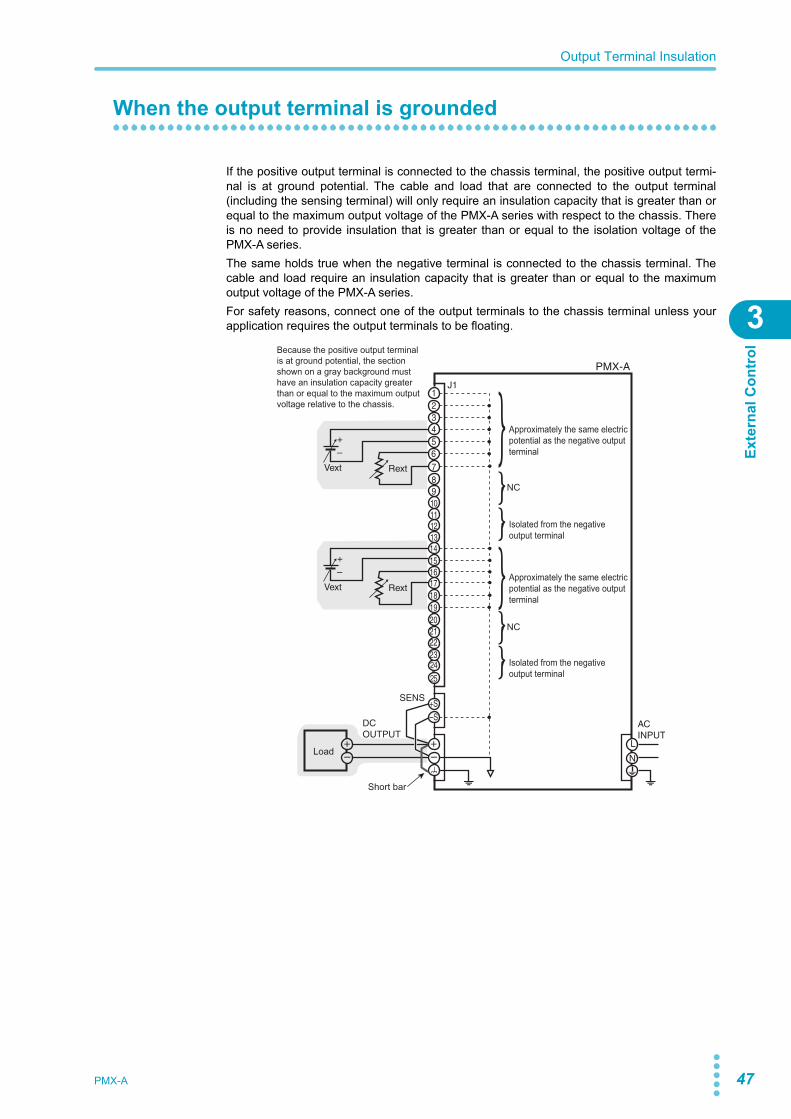
PMX-A 47
Output Terminal Insulation
Exte
rnal
Con
trol
3
When the output terminal is grounded
If the positive output terminal is connected to the chassis terminal, the positive output termi-nal is at ground potential. The cable and load that are connected to the output terminal(including the sensing terminal) will only require an insulation capacity that is greater than orequal to the maximum output voltage of the PMX-A series with respect to the chassis. Thereis no need to provide insulation that is greater than or equal to the isolation voltage of thePMX-A series.The same holds true when the negative terminal is connected to the chassis terminal. Thecable and load require an insulation capacity that is greater than or equal to the maximumoutput voltage of the PMX-A series.For safety reasons, connect one of the output terminals to the chassis terminal unless yourapplication requires the output terminals to be floating.
+–
+–
+
+S
–S
–+–
15161718
14
20212223
19
3456
1213
1110987
12
2425
ACINPUT
DCOUTPUT
J1
SENS
L
N
Approximately the same electric potential as the negative output terminal
Approximately the same electric potential as the negative output terminal
NC
NC
Isolated from the negative output terminal
Isolated from the negative output terminal
Load
Rext
PMX-A
Vext
RextVext
Because the positive output terminal is at ground potential, the section shown on a gray background must have an insulation capacity greater than or equal to the maximum output voltage relative to the chassis.
Short bar

48 PMX-A
Output Terminal Insulation
Cautions when using the external voltage (Vext)
Connect the cables so that output is not shorted. See the following figures for examples ofshorted output.
A connection in which the output is shorted by the grounding of Vext (example of a prohib-ited connection)
A connection in which the output is shorted by the shield (example of a prohibited connec-tion)
CAUTION The signal cable may burn out.• Do not connect the Vext output, that is, leave it floating.• If you are connecting the shield to the Vext side, do not connect the shield to the output ter-
minal of the PMX-A series.
+
+
–
+
–
–
2-core shielded wireVext PMX-A
Output is shortedby the grounding of Vextcausing current to flow.
Ground thepositive output terminal.
Approximately the same electric potential as the negative output terminal
Prohibited×
J1
+
+
–
+
–
–
2-core shielded wireVext PMX-A
Output is shortedby the shieldcausing current to flow.
Ground thepositive output terminal.
Prohibited ×
J1
Approximately the sameelectric potential as the negative output terminal
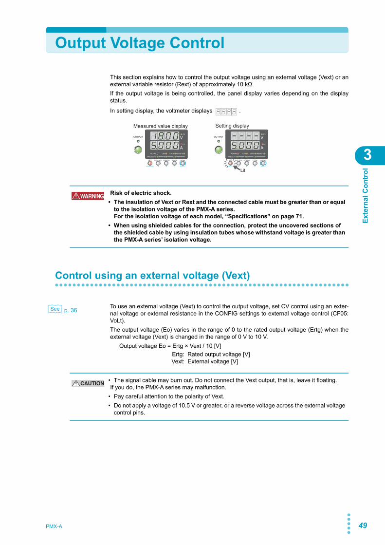
PMX-A 49
Exte
rnal
Con
trol
3
Output Voltage Control
This section explains how to control the output voltage using an external voltage (Vext) or anexternal variable resistor (Rext) of approximately 10 kΩ.If the output voltage is being controlled, the panel display varies depending on the displaystatus.
In setting display, the voltmeter displays .
Control using an external voltage (Vext)
p. 36 To use an external voltage (Vext) to control the output voltage, set CV control using an exter-nal voltage or external resistance in the CONFIG settings to external voltage control (CF05:VoLt).The output voltage (Eo) varies in the range of 0 to the rated output voltage (Ertg) when theexternal voltage (Vext) is changed in the range of 0 V to 10 V.
Output voltage Eo = Ertg × Vext / 10 [V]Ertg: Rated output voltage [V]Vext: External voltage [V]
CBA SHIFTALM CLR
OVP・OCPSET LOCKCONFIG LOCAL
OUTPUT
CBA SHIFTALM CLR
OVP・OCPSET LOCKCONFIG LOCAL
OUTPUTCV
CC
A
V
REMOTELAN LOCKALARM
PRESET B CA
CV
CC
A
V
REMOTELAN LOCKALARM
PRESET B CA
Lit
Measured value display Setting display
WARNING Risk of electric shock.• The insulation of Vext or Rext and the connected cable must be greater than or equal
to the isolation voltage of the PMX-A series.For the isolation voltage of each model, “Specifications” on page 71.
• When using shielded cables for the connection, protect the uncovered sections of the shielded cable by using insulation tubes whose withstand voltage is greater than the PMX-A series’ isolation voltage.
See
CAUTION • The signal cable may burn out. Do not connect the Vext output, that is, leave it floating.If you do, the PMX-A series may malfunction.
• Pay careful attention to the polarity of Vext.• Do not apply a voltage of 10.5 V or greater, or a reverse voltage across the external voltage
control pins.

50 PMX-A
Output Voltage Control
External voltage (Vext) connectionUse a low-noise, stable voltage sourcefor Vext. The noise in Vext is multipliedby the amplification factor of the PMX-A series and appears in the output.Therefore, the output ripple noise maynot meet the specifications of thePMX-A series.To reduce the influence of noise on theoutput, connect a 2-core shielded wireor a twisted-pair wire across Vext, and keep the wire as short as possible. If the wiringbetween the PMX-A series and the external contact is long, it becomes easy for noise to influ-ence the operation of the PMX-A series. Even if you use cables that are designed to sup-press noise, the PMX-A series may not operate properly.
p. 48 If you use a shielded cable, connect the shield to the negative output terminal. If the shieldneeds to be connected to the Vext side, see “Cautions when using the external voltage(Vext)” .Use pins 4 and 5 of the J1 connector.
Control using an external resistance (Rext)
p. 36 By using an external resistance (Rext) to change the reference voltage’s voltage-divider ratio,you can change the output voltage (Eo) to a value in the range of 0 to the 100 % of the ratedoutput voltage (Ertg).To use an external resistance (Rext) to control the output voltage, set CV control using anexternal voltage or external resistance in the CONFIG settings to external resistance control(CF05: rES).The output voltage (Eo) varies in the range of 0 to the rated output voltage (Ertg) when theexternal resistance (Rext) is changed in the range of 0 Ω to 10 kΩ.
Output voltage Eo = Ertg × Rext / 10 [V]Ertg: Rated output voltage [V]Rext: External resistance [kΩ]
External resistance (Rext) connection
For Rext, use a resistor that is rated atapproximately 10 kΩ, 1/2 W or greater,that has a low temperature coefficient,and that will change little over time.Examples of such resistors are metalfilm or wire wound resistors.To reduce the influence of noise on theoutput, connect a 2-core shielded wireor a twisted-pair wire across Rext, andkeep the wire as short as possible. If the wiring between the PMX-A series and the externalcontact is long, it becomes easy for noise to influence the operation of the PMX-A series.Even if you use cables that are designed to suppress noise, the PMX-A series may not oper-ate properly.If you use a shielded cable, connect the shield to the negative output terminal.Use pins 6 and 7 of the J1 connector.
2-core shielded wire ortwisted-pair wire
Vext +–
Output terminals
J14
5
PMX-A
See
See
Connect the external resistor securely.If the external resistor (Rext) becomes loose, an excessive voltage may be applied to the load.
2-core shielded wire ortwisted-pair wire
Output terminals
J16
7
PMX-A
Rext

PMX-A 51
Exte
rnal
Con
trol
3
Output Current Control
This section explains how to control the output current using an external voltage (Vext) or anexternal variable resistor of approximately 10 kΩ (Rext).If the output current is being controlled, the panel display varies depending on the display sta-tus.
In setting display, the ammeter displays .
Control using an external voltage (Vext)
p. 36 To use an external voltage (Vext) to control the output current, set CC control using an exter-nal voltage or external resistance in the CONFIG settings to external voltage control (CF04:VoLt).The output current (Io) varies in the range of 0 to the rated output current (Irtg) when theexternal voltage (Vext) is changed in the range of 0 V to 10 V.
Output current Io = Irtg × Vext / 10 [A]Irtg: Rated output current [A]Vext: External voltage [V]
CBA SHIFTALM CLR
OVP・OCPSET LOCKCONFIG LOCAL
OUTPUT
CBA SHIFTALM CLR
OVP・OCPSET LOCKCONFIG LOCAL
OUTPUTCV
CC
A
V
REMOTELAN LOCKALARM
PRESET B CA
CV
CC
A
V
REMOTELAN LOCKALARM
PRESET B CA
Lit
Measured value display Setting display
WARNING Risk of electric shock.• The insulation of Vext or Rext and the connected cable must be greater than or equal
to the isolation voltage of the PMX-A series.For the isolation voltage of each model, “Specifications” on page 71.
• When using shielded cables for the connection, protect the uncovered sections of the shielded cable by using insulation tubes whose withstand voltage is greater than the PMX-A series’ isolation voltage.
See
CAUTION • The signal cable may burn out. Do not connect the Vext output, that is, leave it floating.If you do, the PMX-A series may malfunction.
• Pay careful attention to the polarity of Vext.• Do not apply a voltage of 10.5 V or greater, or a reverse voltage across the external voltage
control pins.

52 PMX-A
Output Current Control
External voltage (Vext) connectionConnect a low-noise, stable voltagesource to Vext. The noise in Vext is mul-tiplied by the amplification factor of thePMX-A series and appears in the output.Therefore, the output ripple noise maynot meet the specifications of the PMX-Aseries.To reduce the influence of noise on theoutput, connect a 2-core shielded wire ora twisted-pair wire across Vext, and keep the wire as short as possible. If the wiring betweenthe PMX-A series and the external contact is long, it becomes easy for noise to influence theoperation of the PMX-A series. Even if you use cables that are designed to suppress noise,the PMX-A series may not operate properly.
p. 48 If you use a shielded cable, connect the shield to the negative output terminal. If the shieldneeds to be connected to the Vext side, see “Cautions when using the external voltage(Vext)” .Use pins 14 and 15 of the J1 connector.
Control using an external resistance (Rext)
p. 36 By using an external resistance (Rext) to change the reference voltage’s voltage-divider ratio,you can change the output current (Io) to a value in the range of 0 to the 100 % of the ratedoutput current (Irtg).To use an external resistance (Rext) to control the output current, set CC control using anexternal voltage or external resistance in the CONFIG settings to external resistance control(CF04: rES).The output current (Io) varies in the range of 0 to the rated output current (Irtg) when theexternal resistance (Rext) is changed in the range of 0 Ω to 10 kΩ.
Output current Io = Irtg × Rext / 10 [A]Irtg: Rated output current [A]Rext: External resistance [kΩ]
External resistance (Rext) connection
For Rext, use a resistor that is rated atapproximately 10 kΩ, 1/2 W or greater,that has a low temperature coefficient,and that will change little over time. Exam-ples of such resistors are metal film orwire wound resistors.To reduce the influence of noise on theoutput, connect a 2-core shielded wire ora twisted-pair wire across Rext, and keepthe wire as short as possible. If the wiring is long, it becomes easy for noise to influence theoperation of the PMX-A series. Even if you use wires that are designed to suppress noise, thePMX-A series may not operate properly.If you use a shielded cable, connect the shield to the negative output terminal.Use pins 16 and 17 of the J1 connector.
2-core shielded wire ortwisted-pair wire
Vext +–
Output terminals
J114
15
PMX-A
See
See
Connect the external resistor securely.If the external resistor (Rext) becomes loose, an excessive voltage may be applied to the load.
2-core shielded wire ortwisted-pair wire
Output terminals
J116
17
PMX-A
Rext

PMX-A 53
Exte
rnal
Con
trol
3
Controlling the Output On and Off States
This section explains how to use an external contact to control the output on and off states.
To reduce the influence of noise on the output, connect a 2-core shielded wire or a twisted-pair wire across the external contact, and keep the wire as short as possible. If the wiring islong, it becomes easy for noise to influence the operation of the PMX-A series. Even if youuse cables that are designed to suppress noise, the PMX-A series may not operate properly.If you use a shielded cable, connect the shield to the negative output terminal.
p. 36 To use an external contact to control the output on and off states, set the appropriate CON-FIG parameter (CF06: on). Then, select the logic setting from the following two options.• Turn the output on at the falling edge of the LOW signal (CF07: Lo)
Output is turned on when a low (0 V to 0.5 V) signal is applied to pin 18 of the J1 connec-tor or the pin is shorted.
• Turn the output on at the rising edge of the HIGH signal (CF07: Hi)Output is turned on when a high (4.5 V to 5 V) signal is applied to pin 18 of the J1 connec-tor or the pin is opened.
Output on/off control is performed by detecting rising edges or falling edges. Because it is nota level detection, if you want to turn on the output at startup, you need to apply a signal sothat an edge is detected.
Because output off is prioritized, if the output is turned off with an external contact, the OUT-PUT key and OUTP command are disabled.
Controlling the output on and off states (in this example, a high signal is used to turn theoutput on)
WARNING Risk of electric shock.• The insulation of the external contact (S) and the connected cable must be greater
than or equal to the isolation voltage of the PMX-A series.For the isolation voltage of each model, “Specifications” on page 71.
• When using shielded cables for the connection, protect the uncovered sections of the shielded cable by using insulation tubes whose withstand voltage is greater than the PMX-A series’ isolation voltage.
See
On
Off
H = On
L = Off
▼

54 PMX-A
Controlling the Output On and Off States
External contact connectionUse pins 18 and 19 of the J1 connector.The open-circuit voltage across pins 18and 19 is approximately 5 V. The short-cir-cuit current across pins 18 and 19 isapproximately 0.25 mA.Use external contacts that have a contactrating greater than or equal to 0.25 mA at5 Vdc.If two or more units are floating, and youare using a single external contact to clear alarms, use a relay or similar device for the exter-nal contact signal to isolate the signal transmitted to each unit.
For long-distance wiringWhen you are wiring over a great distance, usea small relay and extend the coil side of therelay.
2-core shielded wire ortwisted-pair wire
Output terminals
J118
19
PMX-A
S
S
Extend this line. Relay

PMX-A 55
Exte
rnal
Con
trol
3
External Monitoring
External monitoring of the output voltage and output currentThe J1 connector has monitor outputs for the output voltage and the output current.
Monitor output ratingOutput impedance: 1 kΩ or less, maximum output current: approx. 1 mA
The monitor output signals are used to monitor the DC voltage (mean value). They cannot beused to accurately monitor the AC components (such as ripple and transient response wave-form) of the actual output voltage or current.
External monitoring of the operation statusThe J1 connector has status outputs that can be used to externally monitor the operation sta-tus of the PMX-A series. The following five items make up the status outputs.The outputs are open collector outputs of photocouplers; they are isolated from the internalcircuits of the PMX-A series.The status common is floating (that is, it has an isolation voltage or less).
The maximum ratings of the signal terminals are as follows:Maximum voltage 30 V, maximum current (sink) 8 mA
Pin no. Signal name Description
1 VMON Monitor output of output voltage0 to approx. 10 V for 0 to rated output voltage
2 IMON Monitor output of output current0 to approx. 10 V for 0 to rated output current
3, 5, 15 ACOM Remote control input commonOutput monitor common
CAUTION Shorting VMON and IMON to ACOM may damage the PMX-A series.
Pin no. Signal name Description Circuit
25 STATUS COM Status output common.Photocoupler emitter output.
11 CV STATUS This is set to low level when the PMX-A series is in constant voltage mode.Photocoupler open collector output.
12 CC STATUS This is set to low level when the PMX-A series is in constant current mode.Photocoupler open collector output.
13 ALM STATUS This is set to low level when a protection function is activated.Photocoupler open collector output.
23 OUT ON STATUS This is set to low level when the output is turned on.Photocoupler open collector output.
24 PWR ON STATUS This is set to low level when the POWER switch is turned on.
2511
12
13
23
24

56 PMX-A
This page has been intentionally left blank.

Parallel/Series OperationThis chapter describes the functions of par-allel operation and series operations aswell as the connection, setup, and opera-tion procedures.

58 PMX-A
Parallel Operation
You can connect multiple PMX-As in parallel to increase the current capacity.You cannot perform master-slave series operation, which would enable you to control multi-ple slave units from a single master unit.Specify the same output setting for the power supplies that are connected in parallel.
Parallel operation features
Voltage display and current displayThe voltage or current is displayed on each unit.The voltmeter displays the voltage at the output terminals of each device.To calculate the total output current, add the current values of each unit.
Remote sensing (only on models whose rated output voltage is 18 V or 35 V)
p. 18 This is available.
External control
chapte 3 This is available.
External monitoring
p. 55 • External monitoring of the output voltage (VMON)You can monitor the output voltage of each unit.
• External monitoring of the output current (IMON)You can monitor the output current of each unit. To determine the total output current, addthe value displayed on the ammeter of each unit together.
• Status monitorsYou can monitor the status of the following items from each unit: constant-voltage mode(CV STATUS), constant-current mode (CC STATUS), output on (OUTON STATUS),POWER switch on (POWERON STATUS), and alarms (ALM STATUS).
CAUTION Otherwise, the PMX-A series may not operate properly. Use the same models for parallel operation.
OUTPUTCV
CC
A
V
REMOTELAN LOCKALARM
PRESET B CA
Example of the panel displays when two units operate in parallel
OUTPUTCV
CC
A
V
REMOTELAN LOCKALARM
PRESET B CA
Unit 1 Unit 2
CAUTION Do not connect the common wire (ACOM and DCOM) of each device together. If the load wire comes loose, the common wire may break.
See
See
See

PMX-A 59
Parallel Operation
Para
llel/S
erie
s O
pera
tion
4
AlarmThe alarms that are detected on a single unit are also detected during parallel operation.
Clearing alarms
p. 27 Press ALM CLR (SHIFT + SET) or turn off the POWER switch. Fix the problem that causedthe alarm, and turn the POWER switch back on.
Parallel operation connection
Connecting the load
See
WARNING Risk of electric shock. Turn the POWER switch off before you touch the output termi-nals.
CAUTION • When you connect the output terminals to the chassis terminals, be sure to connect the same polarity output terminals (positive or negative) to the chassis terminals. If you con-nect different polarity output terminals to the chassis terminal, the output will be grounded through the power cord’s GND wire. Not only will this make the output incorrect, it will also cause the chassis terminal cable to burn out.
• To prevent oscillation, connect an electrolytic capacitor with a capacitance of a few hundred µF to a few ten thousand µF across the load as necessary. If the wires are long, the wiring inductance and capacitance can cause phase shifting at a level that can not be ignored. This may lead to oscillation.Use an electrolytic capacitor that has a withstand voltage that is at least 120 % of the rated output voltage.
• Twist the positive and negative cables together, and make the connection to the load as short as possible. Oscillation may occur as a result of wiring inductance.
Load orrelay terminal block
Connect the short bar to the negativeor positive output terminal.For all power supplies, connect to the same polarity.
Unit 1
PMX-A
PMX-A
Unit 2
Output terminals
Chassis terminal
Output terminals
Chassis terminal
Load connections for parallel operation of two units (In this example, the negative side is connected to the chassis terminal.)

60 PMX-A
Parallel Operation
1 Turn off all the PMX-As that you want to connect in parallel.
2 Connect the load cables to the output terminals of each unit.
p. 16 3 Connect the load cables of each unit to the load. If you are going to usea relay terminal block, make sure that the wires used to connect theunits are as short as possible.Use load cables that have sufficient current capacity. Use load cables of equivalentlength and cross-sectional area to connect to each unit, and wire the cables so thatthey are as short as possible.
4 Connect the output terminals (positive or negative) of the units you wantto operate in parallel to the chassis terminals.Connect the same polarity output terminals on each unit.If you are using the units under floating conditions, do not connect the terminals.
Parallel operation settings
Setting the voltage and currentSet the voltage and current on each unit. The current that is output is the total of the currentsof all the units.Set the voltage and current to the same values on each unit.
Setting the overvoltage protection (OVP) and overcurrent protec-tion (OCP)
p. 28 You have to set the overvoltage protection (OVP) and overcurrent protection (OCP) on bothunits.Specify the same values on each unit.
Starting parallel operation
Turning the power on and offTurn on or off the POWER switch of each unit.
Turning the output on and offTurn on or off the OUTPUT switch of each unit.
See
See
CAUTION After you turn the POWER switch off, wait at least 10 seconds after the panel display turns off before you turn the POWER switch back on. Repeatedly turning the POWER switch on and off at short intervals, this will shorten the service life of the POWER switch, internal input fuse, and other components.

PMX-A 61
Para
llel/S
erie
s O
pera
tion
4
Series Operation
You can connect multiple PMX-As in series to increase the output voltage.The number of units that can be connected in series depends on the output voltage and theisolation voltage of each unit. The total of the output voltages of the power supplies con-nected in series will be applied to the load.
Number of power supplies to connect in seriesThe number of units that can be connected in series depends on the output voltage and theisolation voltage of each model.
Example For the PMX18-5A, the isolation voltage is 70 V. The maximum number of unitsis determined as 70/18 = 3.888, so up to 3 units can be connected.
Series operation features
Voltage display and current displayThe voltage or current is displayed on each unit. To calculate the total output voltage, add thevoltage values of each unit.
Remote sensingThis is not available.
External control
chapter 3 This is available.
WARNING Risk of electric shock.Make sure that the maximum output voltage of the power supplies connected in series does not exceed the isolation voltage. Always observe the maximum number of units connected in series. For details on the isolation voltage of each model see the specifications.
OUTPUTCV
CC
A
V
REMOTELAN LOCKALARM
PRESET B CA
Unit 1 Unit 2
Example of the panel displays when two units operate in series
OUTPUTCV
CC
A
V
REMOTELAN LOCKALARM
PRESET B CA
See
CAUTION Do not connect the common wire (ACOM and DCOM) of each device together. The common potential of each unit is different during series operation.

62 PMX-A
Series Operation
External monitoring
p. 55 • External monitoring of the output voltage (VMON)You can monitor the output voltage of each unit.To calculate the total output voltage, add the monitored values of each unit.
• External monitoring of the output current (IMON)You can monitor the output current of each unit.
• Status monitorsYou can monitor the status of the following items from each unit: constant-voltage mode(CV STATUS), constant-current mode (CC STATUS), output on (OUTON STATUS),POWER switch on (POWERON STATUS), and alarms (ALM STATUS).
AlarmAll the alarms that are detected on a single unit are also detected during series operation.
Clearing alarms
p. 27 Press ALM CLR (SHIFT + SET) or turn off the POWER switch. Fix the problem that causedthe alarm, and turn the POWER switch back on.
Series operation connection
Connecting the load
WARNING When monitoring is in progress, be careful of shorts and electric shocks. When moni-toring the output voltage or output current during series operation, the electric poten-tial of the common of each unit’s monitor signal is different.
See
See
WARNING Risk of electric shock. Turn the POWER switch off before you touch the output termi-nals.
CAUTION To prevent oscillation, connect an electrolytic capacitor with a capacitance of a few hundred µF to a few ten thousand µF across the load as necessary. If the wires are long, the wiring inductance and capacitance can cause phase shifting at a level that can not be ignored. This may lead to oscillation.Use an electrolytic capacitor with a withstand voltage that is 120% or more of the total of the rated output voltages of the PMX-As that are connected in series.
Load orrelay terminal block
Unit 1
PMX-A
PMX-A
Unit 2
Output terminals
Chassis terminal
Output terminals
Chassis terminalConnect the short bar to any one unit. Connect it to the negative or positive output terminal.

PMX-A 63
Series Operation
Para
llel/S
erie
s O
pera
tion
4
1 Turn off all the PMX-As that you want to connect in series.
p. 16 2 Use load cables to connect each unit to the load or relay terminal block.Use load cables that have sufficient current capacity. Wire the load cables so that theyare as short as possible. If the voltage drop in the load cable is large, the difference inelectric potential between power supply units and the load regulation become large.
3 Connect the output terminals of each unit in series.
4 Connect the positive or negative output terminal of one of the units tothe chassis terminal with the short bar.
Series operation settings
Setting the voltage and currentSet the voltage and current on each unit. The voltage that is output is the total of the voltagesof all the units.Set the current to the same value on each unit.
Setting the overvoltage protection (OVP) and overcurrent protec-tion (OCP)
p. 28 You have to set the overvoltage protection (OVP) and overcurrent protection (OCP) on bothunits.Specify the same values on each unit.
Starting series operation
Turning the power on and offTurn on or off the POWER switch of each unit.
Turning the output on and offTurn on or off the OUTPUT key of each unit.
See
See
CAUTION After you turn the POWER switch off, wait at least 10 seconds after the panel display turns off before you turn the POWER switch back on. Repeatedly turning the POWER switch on and off at short intervals, this will shorten the service life of the POWER switch, internal input fuse, and other components.

64 PMX-A
This page has been intentionally left blank.

MaintenanceThis chapter explains how to perform cali-bration.

66 PMX-A
Calibration
The product is calibrated before shipment. To maintain long-term performance, we recom-mend periodic calibration.If you are going to calibrate the product, follow the procedure below.
Calibration overview
The following 10 parameters can be calibrated.Calibration is performed for 1 % and 100 % full scale.• Output voltage offset (1 %) • Output voltage full scale (100 %)• Voltmeter offset (1 %) • Voltmeter full scale (100 %)• Output current offset (1 %) • Output current full scale (100 %)• Ammeter offset (1 %) • Ammeter full scale (100 %)• Overvoltage protection (OVP) • Overcurrent protection (OCP)
Required devices• A DC voltmeter (DVM) with a measurement accuracy of 0.02 % or better• A shunt resistor with an accuracy of 0.1 % or better, or an ammeter that can supply the
rated output current of the PMX-A series to be calibrated
EnvironmentPerform calibration in the following environment.
• Temperature: 23 °C ± 5 °C• Humidity: 80 %rh or less
To minimize the calibration error due to initial drift, warm up the PMX-A series for at least30 minutes before calibration. In addition, warm up the DVM and shunt resistor for as long asis necessary.

PMX-A 67
Calibration
Mai
nten
ance
5
Calibration procedure
There are voltage system and current system calibration parameters.During calibration, you can change the resolution.While holding down LOCAL, turn the CURRENT knob to reduce the amount of change.
1 While holding down SET and LOCAL, turn the POWER switch on.The calibration screen appears.
2 Turn the Voltage knob to select a calibration parameter.Each time you turn the Voltage knob, the calibration parameter changes.
3 Press SET to save the calibration settings and end calibration. PressLOCK to not save the calibration settings and end calibration.
Calibration mode display
The voltmeter displays the calibration parameter,and the ammeter displays the calibration data.The calibration parameters change in the followingorder.
WARNING Risk of electric shock.• Turn the POWER switch off before you touch the output terminals.• Be sure to connect the output terminal to the chassis terminal.
Output voltage offset▼
Output voltage full scale▼
Output current offset▼
Output current full scale▼
Voltmeter offset▼
Voltmeter full scale▼
Ammeter offset▼
Ammeter full scale▼
Overvoltage protection (OVP)▼
Overcurrent protection (OCP)
CV
CC
A
V
REMOTELAN LOCKALARM
PRESET B CA
Calibration data
Calibration parameter

68 PMX-A
Calibration
Voltage system calibration
1 Turn the POWER switch off.
2 Connect a DVM to the output terminals.
Output voltage offsetUse the VOLTAGE knob to select the item, and turn on the output. Turn the CURRENTknob to set the DVM’s output voltage reading to 1 % of the rated voltage.
Output voltage full scaleUse the VOLTAGE knob to select the item, and turn on the output. Turn the CURRENTknob to set the DVM’s output voltage reading to 100 % of the rated voltage.
Voltmeter offsetBe sure to calibrate the output voltage before calibrating the voltmeter.
1 Use the VOLTAGE knob to select the item, and turn on the output.
2 Press OVP•OCP.
3 While viewing the PMX-A voltmeter, turn the CURRENT knob to matchthe PMX-A voltage reading to the DVM reading.
Voltmeter full scaleBe sure to calibrate the output voltage before calibrating the voltmeter.
1 Use the VOLTAGE knob to select the item, and turn on the output.
2 Press OVP•OCP.
3 Turn the CURRENT knob to match the PMX-A voltage reading to the DVMreading.
Overvoltage protection (OVP)
1 Use the VOLTAGE knob to select the item, and turn on the output.
2 Press OVP•OCP.The OVP•OCP key lights, and automatic calibration starts.
3 When the calibration is complete, the OVP • OCP key turns off.
DVMPMX-A
HILO
Output terminals
Chassis terminal
If you press LOCK during calibration (while the SET key is lit), the calibration will end without the calibration settings being saved.

PMX-A 69
Calibration
Mai
nten
ance
5
Current system calibration
1 Turn the POWER switch off.
2 Connect a shunt to the output termi-nals, and connect a DVM across theshunt.
Output current offsetUse the VOLTAGE knob to select the item, and turn on the output. Turn the CURRENTknob to set the DVM’s output current reading (converted current value) to 1 % of therated current.
Output current full scaleUse the VOLTAGE knob to select the item, and turn on the output. Turn the CURRENTknob to set the DVM’s output current reading (converted current value) to 100 % of therated current.
Ammeter offsetBe sure to calibrate the output current before calibrating the ammeter.
1 Use the VOLTAGE knob to select the item, and turn on the output.
2 Press OVP•OCP.
3 While viewing the PMX-A ammeter, turn the CURRENT knob to match thePMX-A current reading to the DVM reading.
Ammeter full scaleBe sure to calibrate the output current before calibrating the ammeter.
1 Use the VOLTAGE knob to select the item, and turn on the output.
2 Press OVP•OCP.
3 Turn the CURRENT knob to match the PMX-A current reading to the DVMreading (converted current value).
Overcurrent protection (OCP)
1 Use the VOLTAGE knob to select the item, and turn on the output.
2 Press OVP•OCP.The OVP•OCP key lights, and automatic calibration starts.
3 When the calibration is complete, the OVP • OCP key turns off.
Shunt or ammeter
DVM
PMX-A
HILO
Output terminals
Chassis terminal
If you press LOCK during calibration (while the SET key is lit), the calibration will end without the calibration settings being saved.

70 PMX-A
This page has been intentionally left blank.
SpecificationsThis chapter describes the specificationsand gives the dimensions of the PMX-A.

72 PMX-A
PMX18-2A/ PMX18-5A/ PMX35-1A/ PMX35-3A
Unless specified otherwise, the specifications are for the following settings and conditions.
• Loads are pure resistive loads.• The warm-up time is 30 minutes (with current flowing).• Negative output is connected to the chassis terminal using the short bar.• Values indicated by “TYP” are typical values. They are not guaranteed performance val-
ues.• Values indicated by “rating” are rated values.• Values indicated by “setting” are setting values.• Values indicated by “reading” are readout values.• Rated load and no load are defined as follows:
In constant-voltage mode (when the output current is set to a value greater than or equalto the maximum output current with rated output voltage)
Rated load: Refers to a resistive load that, when the rated output voltage is applied,makes the flowing current 95 % to 100 % of the maximum output currentwith rated output voltage.
No load: Refers to a load through which no output current flows. In other words,refers to an open load (no load being connected).
In constant-current mode (when the output voltage is set to a value greater than or equalto the maximum output voltage with rated output current)
Rated load: Refers to a resistive load that, when the rated output current flows, makesthe voltage drop to 95 % to 100 % of the maximum output voltage withrated output current.Including the voltage drop in the load cables, the PMX-A output voltagemust not exceed the maximum output voltage with rated output current.
No load: Refers to a resistive load that, when the rated output current flows, makesthe voltage drop to 10 % of the maximum output voltage with rated outputcurrent or 1 V whichever is higher.
PMX18-2A/ PMX18-5A/ PMX35-1A/ PMX35-3A
AC input
PMX18-2A PMX18-5A PMX35-1A PMX35-3A
Nominal input rating 100 Vac1, 50 Hz/ 60 Hz, single phase
1 117 Vac, 200 Vac, 217 Vac and 234 Vac are factory options.
Input voltage range ± 10 %
Input frequency range 47 Hz to 63 Hz
Inrush current (MAX)2
2 Excludes the charge current component that flows through the capacitor of the internal EMC filtercircuit immediately after the POWER switch is turned on (for approximately 1 ms).
50 Amax or less 60 Amax or less 45 Amax or less 60 Amax or less
Power (MAX)3
3 With the rated load.
150 VA 310 VA 150 VA 310 VA
PMX18-2A/ PMX18-5A/ PMX35-1A/ PMX35-3A
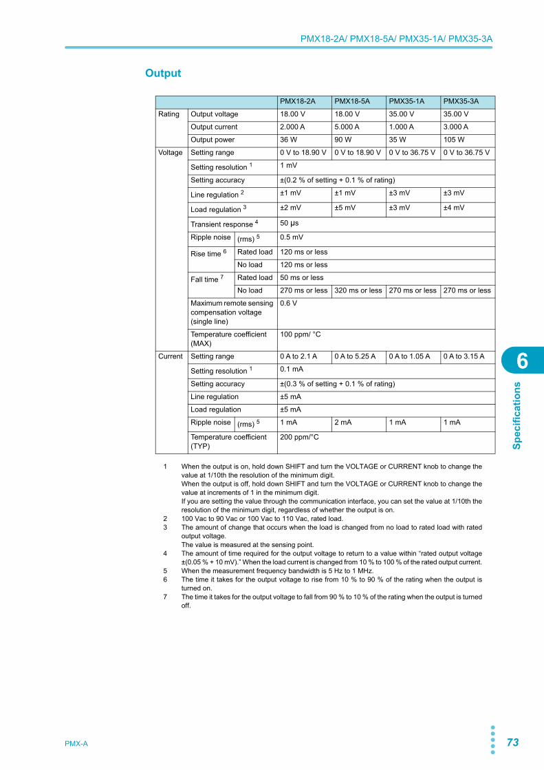
PMX-A 73
PMX18-2A/ PMX18-5A/ PMX35-1A/ PMX35-3A
Spec
ifica
tions
6
Output
PMX18-2A PMX18-5A PMX35-1A PMX35-3A
Rating Output voltage 18.00 V 18.00 V 35.00 V 35.00 V
Output current 2.000 A 5.000 A 1.000 A 3.000 A
Output power 36 W 90 W 35 W 105 W
Voltage Setting range 0 V to 18.90 V 0 V to 18.90 V 0 V to 36.75 V 0 V to 36.75 V
Setting resolution 1
1 When the output is on, hold down SHIFT and turn the VOLTAGE or CURRENT knob to change thevalue at 1/10th the resolution of the minimum digit.When the output is off, hold down SHIFT and turn the VOLTAGE or CURRENT knob to change thevalue at increments of 1 in the minimum digit.If you are setting the value through the communication interface, you can set the value at 1/10th theresolution of the minimum digit, regardless of whether the output is on.
1 mV
Setting accuracy ±(0.2 % of setting + 0.1 % of rating)
Line regulation 2
2 100 Vac to 90 Vac or 100 Vac to 110 Vac, rated load.
±1 mV ±1 mV ±3 mV ±3 mV
Load regulation 3
3 The amount of change that occurs when the load is changed from no load to rated load with ratedoutput voltage.The value is measured at the sensing point.
±2 mV ±5 mV ±3 mV ±4 mV
Transient response 4
4 The amount of time required for the output voltage to return to a value within “rated output voltage±(0.05 % + 10 mV).” When the load current is changed from 10 % to 100 % of the rated output current.
50 µs
Ripple noise (rms) 5
5 When the measurement frequency bandwidth is 5 Hz to 1 MHz.
0.5 mV
Rise time 6
6 The time it takes for the output voltage to rise from 10 % to 90 % of the rating when the output isturned on.
Rated load 120 ms or less
No load 120 ms or less
Fall time 7
7 The time it takes for the output voltage to fall from 90 % to 10 % of the rating when the output is turnedoff.
Rated load 50 ms or less
No load 270 ms or less 320 ms or less 270 ms or less 270 ms or less
Maximum remote sensing compensation voltage (single line)
0.6 V
Temperature coefficient (MAX)
100 ppm/ °C
Current Setting range 0 A to 2.1 A 0 A to 5.25 A 0 A to 1.05 A 0 A to 3.15 A
Setting resolution 1 0.1 mA
Setting accuracy ±(0.3 % of setting + 0.1 % of rating)
Line regulation ±5 mA
Load regulation ±5 mA
Ripple noise (rms) 5 1 mA 2 mA 1 mA 1 mA
Temperature coefficient (TYP)
200 ppm/°C

74 PMX-A
PMX18-2A/ PMX18-5A/ PMX35-1A/ PMX35-3A
Display function
Protection functions
PMX18-2A PMX18-5A PMX35-1A PMX35-3A
Voltage display Maximum display 99.99 (fixed decimal point)
Display accuracy 1
1 Ambient temperature at 23 °C ±5 °C.
±(0.5 % of reading + 2 digits)
Current display Maximum display 9.999 (fixed decimal point)
Display accuracy 1 ±(1 % of reading + 5 digits)
Operation display
OUTPUT ON/OFF Output on: OUTPUT LED lights in green.Output off: OUTPUT LED turns off.
CV operation CV LED lights in green.
CC operation CC LED lights in red.
Alarm operation ALARM LED lights in red when a protection function has been activated.
Remote operation REMOTE LED lights in green during remote control.
LAN operation
LAN LED lights or blinks depending on the LAN communica-tion status.
No fault status: Lights in green.Fault status: Lights in red.Standby status: Lights in orange.WEB identify status: Blinks green.
Key lock operation LOCK LED lights in green when the keys are locked.
Preset memory When a preset memory entry is being used, the PRESET A, B, or C LED lights in green.
PMX18-2A PMX18-5A PMX35-1A PMX35-3A
Overvoltage protection (OVP)
Operation Turns the output off, displays OVP, and lights ALARM
Setting range
1.8 V to 19.8 V 1.8 V to 19.8 V 3.5 V to 38.5 V 3.5 V to 38.5 V
(10 % to 110 % of the rated output voltage)
Setting accuracy
±(1 % of rating)
Overcurrent protection (OCP)
Operation 1
1 This does not protect against the discharge current peak that is generated from the capacitors insidethe PMX-A output section when the load is changed suddenly.
Turns the output off, displays OCP, and lights ALARM
Setting range
0.2 A to 2.2 A 0.5 A to 5.5 A 0.1 A to 1.1 A 0.3 A to 3.3 A
(10 % to 110 % of the rated output current)
Setting range
±(1 % of rating)
Overheat protection (OHP)
Operation Turns the output off, displays OHP, and lights ALARM

PMX-A 75
PMX18-2A/ PMX18-5A/ PMX35-1A/ PMX35-3A
Spec
ifica
tions
6
Signal output
Control features
Other features
Common specifications
Monitor signal output1 2
1 When remote sensing is used, connect the monitor signal's common line to the negative S terminalof the sensing terminal. When remote sensing is not used, connect it to the negative output terminal.
2 J1 connector on the rear panel
Voltage monitor (VMON)
At rated voltageoutput
10.00 V ±0.1 V
At 0 V output 0.00 V ±0.1 V
Current monitor (IMON)
At rated currentoutput
10.00 V ±0.1 V
At 0 A output 0.00 V ±0.1 V
Status signal output 2 3
3 Photocoupler open collector output;maximum voltage 30 V, maximum current (sink) 8 mA; isolated from the output and control circuits;status commons are floating (isolation voltage or less); and status signals are not mutually isolated.
OUTON STATUS Turns on when the output is on
CV STATUS Turns on during CV operation
CC STATUS Turns on during CC operation
ALM STATUS Turns on when an alarm has been activated
PWR ON STATUS Turns on when the power is turned on
Common specifications
External control 1
1 J1 connector on the rear panel
EXT-V CV CONT (CV external voltage control)
0 % to 100 % of the rated output voltage in the range of 0 V to 10 V.
Accuracy 1 % of rating +10 mV
EXT-R CV CONT(CV external resistance control)
0 % to 100 % of the rated output voltage in the range of 0 Ω to 10 kΩ.
Accurac 1 % of rating +10 mV
EXT-V CC CONT (CC external voltage control)
0 % to 100 % of the rated output current in the range of 0 V to 10 V
Accuracy 1 % of rating +5 mV
EXT-R CC CONT(CC external resistance control)
0 % to 100 % of the rated output current in the range of 0 Ω to 10 kΩ.
Accurac 1 % of rating +5 mV
OUTPUT ON/OFF CONT(Output on/off control)
Possible logic selections:Turn the output on using a LOW (0 V to 0.5 V) or short-cir-cuit, turn the output off using a HIGH (4.5 V to 5 V) or open-circuit.Turn the output on using a HIGH (4.5 V to 5 V) or open-cir-cuit, turn the output off using a LOW (0 V to 0.5 V) or short-circuit.
Common specifications
Preset memory Up to three sets of the following settings can be saved: the set voltage and the set current.
Key lock Select from the following three modes.Loc1: Locks the operation of all keys except the OUTPUT key and the preset memory A, B, and C keys.Loc2: Locks the operation of all keys except than the OUTPUT key.Loc3: Locks the operation of all keys and the rotary knob.

76 PMX-A
PMX18-2A/ PMX18-5A/ PMX35-1A/ PMX35-3A
Interface
Common specifications
Common specifications
Software protocol IEEE Std 488.2-1992
Command language Complies with SCPI Specification 1999.0
RS232C Hardware Complies with the EIA232D specifications
D-SUB9 pin connector (male) 1
1 Use a cross cable (null modem cable).
Baud rate: 19200 bps fixed
Data length: 8 bits, Stop bits: 1 bit, Parity bit: None
No flow control
Program message terminator
LF during reception, LF during transmission
USB Hardware Complies with the USB 2.0 specifications. Baud rate:12 Mbps (full speed).
Socket B Type
Program message terminator
LF or EOM during reception, LF + EOM during transmission
Device class Complies with the USBTMC-USB488 device class specifica-tions
LAN Hardware IEEE 802.3 100Base-TX/10Base-T EthernetComplies with the LXI 1.4 Core 2011
IPv4, RJ-45 connector 2
2 Category 5; use a straight cable.
Communication protocol
VXI-11, HiSLIP, or SCPI-RAW
Program message terminator
VXI-11 and HiSLIP:LF or END during reception, LF + END during transmissionSCPI-RAW:LF during reception, LF during transmission

PMX-A 77
PMX18-2A/ PMX18-5A/ PMX35-1A/ PMX35-3A
Spec
ifica
tions
6
General specifications
PMX18-2A PMX18-5A PMX35-1A PMX35-3A
Weight (main unit only) Approxi-mately 5 kg (11.02 lb)
Approxi-mately 6 kg (13.23 lb)
Approxi-mately 5 kg (11.02 lb)
Approxi-mately 6 kg (13.23 lb)
Dimensions See the outline drawing
Environ-mental conditions
Operating environment Indoor use, overvoltage category II
Operating temperature 0 °C to +40 °C (32 °F to +104 °F)
Operating humidity 20 %rh to 85 %rh (no condensation)
Storage temperature −25 °C to +70 °C (−13 °F to +158 °F)
Storage humidity 90 %rh or less (no condensation)
Altitude Up to 2000 m
Cooling method Forced air cooling using fan
Grounding polarity Negative grounding or positive grounding possible
Isolation voltage ±70 Vdc
With-stand voltage
Between input and FG No abnormalities at 1500 Vac for 1 minute
Between input and output No abnormalities at 2100 Vac for 1 minute
Between output and FG No abnormalities at 1600 Vdc for 1 minute
Insulation resistance
Between input and FG 500 Vdc, 30 MΩ or more
Between input and output 500 Vdc, 30 MΩ or more
Between input and output 500 Vdc, 30 MΩ or more
Electromagnetic compatibility 1 2
1 Does not apply to specially ordered or modified PMX-As.2 Limited to products that have the CE mark on their panels.
CE mark does not apply unless you use a USB cable with a ferrite core.[Kikusui-recommended ca-ble: Elecom U2C-BF series USB cable with a ferrite core, less than 3 m]
Complies with the requirements of the following directive and standards.EMC Directive 2014/30/EUEN 61326-1 (Class A3)
EN 55011 (Class A3, Group 14)EN 61000-3-2EN 61000-3-3
Applicable under the following conditionsThe maximum length of all cabling and wiring connected to the PMX-A must be less than 3 m.
3 This is a Class A equipment. The PMX-A is intended for use in an industrial environment. This prod-uct may cause interference if used in residential areas. Such use must be avoided unless the usertakes special measures to reduce electromagnetic emissions to prevent interference to the recep-tion of radio and television broadcasts.
4 This is a Group 1 equipment. The PMX-A does not generate and/or use intentionally radio-frequencyenergy, in the from of electromagnetic radiation, inductive and/or capacitive coupling, for the treat-ment of material or inspection/analysis purpose.
Safety 1 Complies with the requirements of the following directive and standard. Low Voltage Directive 2014/35/EU2
EN 61010-1 (Class I5, Pollution degree 26)
5 This is a Class I equipment. Be sure to ground the PMX-A's protective conductor terminal. The safe-ty of this product is only guaranteed when the product is properly grounded.
6 Pollution is addition of foreign matter (solid, liquid or gaseous) that may produce a reduction of di-electric strength or surface resistivity. Pollution Degree 2 assumes that only non-conductive pollu-tion will occur except for an occasional temporary conductivity caused by condensation.
Accesso-ries
Power cord 1 pc.
Packing list 1 copy
Quick reference Japanese:1 copy, English:1 copy, Chinese:1 copy
Safety precautions 1 copy
CD-ROM 1 disc

78 PMX-A
PMX70-1A/ PMX110-0.6A/ PMX250-0.25A/ PMX350-0.2A/ PMX500-0.1A
PMX70-1A/ PMX110-0.6A/ PMX250-0.25A/ PMX350-0.2A/ PMX500-0.1A
AC input
PMX70-1A PMX110-0.6A PMX250-0.25A PMX350-0.2A PMX500-0.1A
Nominal input rating 100 Vac1, 50 Hz/ 60 Hz, single phase
Input voltage range ± 10 %
Input frequency range 47 Hz to 63 Hz
Inrush current (MAX)2 65 Amax or less 55 Amax or less 40 Amax or less 55 Amax or less 40 Amax or less
Power (MAX)3 230 VA 210 VA 210 VA 230 VA 170 VA
1 117 Vac, 200 Vac, 217 Vac and 234 Vac are factory options.2 Excludes the charge current component that flows through the capacitor of the internal EMC filter circuit immediately
after the POWER switch is turned on (for approximately 1 ms).3 With the rated load.
PMX70-1A/ PMX110-0.6A/ PMX250-0.25A/ PMX350-0.2A/ PMX500-0.1A

PMX-A 79
PMX70-1A/ PMX110-0.6A/ PMX250-0.25A/ PMX350-0.2A/ PMX500-0.1A
Spec
ifica
tions
6
Output
PMX70-1A PMX110-0.6A PMX250-0.25A PMX350-0.2A PMX500-0.1A
Rating Output voltage 70.00 V 110.0 V 250.0 V 350.0 V 500.0 V
Output current 1.000 A 0.600 A 0.250 A 0.200 A 0.100 A
Output power 70 W 66 W 62.5 W 70 W 50 W
Voltage Setting range 0 V to 73.5 V 0 V to 115.5 V 0 V to 262.5 V 0 V to 367.5 V 0 V to 525.0 V
Setting resolution 1 2 mV 10 mV
Setting accuracy ±(0.2 % of setting + 0.1 % of rating)
Line regulation 2 ±5 mV ±7 mV ±15 mV ±25 mV ±30 mV
Load regulation 3 ±5 mV ±7 mV ±15 mV ±25 mV ±30 mV
Transient response 4 100 µs
Ripple noise (rms) 5 1 mV 2 mV 3 mV 5 mV 10 mV
Rise time 6 Rated load 150 ms or less 120 ms or less 120 ms or less 150 ms or less 120 ms or less
No load 150 ms or less 120 ms or less 120 ms or less 150 ms or less 120 ms or less
Fall time 7 Rated load 50 ms or less 50 ms or less 50 ms or less 80 ms or less 50 ms or less
No load 270 ms or less 120 ms or less8 120 ms or less8 220 ms or less 60 ms or less
Maximum remote sensing compensation voltage (single line)9
--
Temperature coefficient (MAX)
100 ppm/ °C
Current Setting range 0 A to 1.050 A 0 A to 0.630 A 0 A to 0.262 A 0 A to 0.210 A 0 A to 0.105 A
Setting resolution 1 0.1 mA
Setting accuracy ±(0.3 % of setting + 0.1 % of rating)
Line regulation ±2 mA ±2 mA ±1 mA ±1 mA ±1 mA
Load regulation ±5 mA ±5 mA ±5 mA ±5 mA ±3 mA
Ripple noise (rms) 5 1 mA
Temperature coefficient (TYP)
200 ppm/°C
1 When the output is on, hold down SHIFT and turn the VOLTAGE or CURRENT knob to change the value at 1/10th the res-olution of the minimum digit. However, when you set the voltage on the PMX70-1A, the value changes at 1/5th the resolutionof the minimum digit.When the output is off, hold down SHIFT and turn the VOLTAGE or CURRENT knob to change the value at increments of1 in the minimum digit.If you are setting the value through the communication interface, you can set the value at 1/10th the resolution of the min-imum digit, regardless of whether the output is on.
2 100 Vac to 90 Vac or 100 Vac to 110 Vac, rated load.3 The amount of change that occurs when the load is changed from no load to rated load with rated output voltage.
The value is measured at the sensing point.4 The amount of time required for the output voltage to return to a value within “rated output voltage ±(0.05 % + 10 mV).”
When the load current is changed from 10 % to 100 % of the rated output current.5 When the measurement frequency bandwidth is 5 Hz to 1 MHz.6 The time it takes for the output voltage to rise from 10 % to 90 % of the rating when the output is turned on.7 The time it takes for the output voltage to fall from 90 % to 10 % of the rating when the output is turned off.8 At the rated output voltage. The fall time increases at voltages less than the rated output voltage.9 The remote sensing function is not available.

80 PMX-A
PMX70-1A/ PMX110-0.6A/ PMX250-0.25A/ PMX350-0.2A/ PMX500-0.1A
Display function
Protection functions
PMX70-1A PMX110-0.6A PMX250-0.25A PMX350-0.2A PMX500-0.1A
Voltage display
Maximum display 99.99 (fixed decimal point))
999.9 (fixed decimal point)
Display accuracy 1 ±(0.5 % of reading + 2 digits)
Current display
Maximum display 9.999 (fixed decimal point)
Display accuracy 1 ±(1 % of reading + 5 digits)
Operation display
OUTPUT ON/OFF Output on: OUTPUT LED lights in green.Output off: OUTPUT LED turns off.
CV operation CV LED lights in green.
CC operation CC LED lights in red.
Alarm operation ALARM LED lights in red when a protection function has been activated.
Remote operation REMOTE LED lights in green during remote control.
LAN operation
LAN LED lights or blinks depending on the LAN communication status.No fault status: Lights in green.Fault status: Lights in red.Standby status: Lights in orange.WEB identify status: Blinks green.
Key lock operation LOCK LED lights in green when the keys are locked.
Preset memory When a preset memory entry is being used, the PRESET A, B, or C LED lights in green.
1 Ambient temperature at 23 °C ±5 °C.
PMX70-1A PMX110-0.6A PMX250-0.25A PMX350-0.2A PMX500-0.1A
Overvoltageprotection (OVP)
Operation Turns the output off, displays OVP, and lights ALARM
Setting range
7 V to 77.00 V 11 V to 121.0 V 25 V to 275.0 V 35 V to 385.0 V 50 V to 550.0 V
(10 % to 110 % of the rated output voltage)
Setting accuracy
±(1 % of rating)
Overcurrent protection (OCP)
Operation1
Turns the output off, displays OCP, and lights ALARM
Setting range
0.100 A to 1.100 A
0.060 A to 0.660 A
0.025 A to 0.275 A
0.020 A to 0.220 A
0.010 A to 0.110 A
(10 % to 110 % of the rated output current)
Setting range
±(1 % of rating)
Overheat protection (OHP)
Operation Turns the output off, displays OHP, and lights ALARM
1 This does not protect against the discharge current peak that is generated from the capacitors inside the PMX-A outputsection when the load is changed suddenly.

PMX-A 81
PMX70-1A/ PMX110-0.6A/ PMX250-0.25A/ PMX350-0.2A/ PMX500-0.1A
Spec
ifica
tions
6
Signal output
Control features
Other features
Common specifications
Monitor signal output1 2
1 When remote sensing is used, connect the monitor signal's common line to the negative S terminalof the sensing terminal. When remote sensing is not used, connect it to the negative output terminal.
2 J1 connector on the rear panel
Voltage monitor (VMON)
At rated voltageoutput
10.00 V ±0.1 V
At 0 V output 0.00 V ±0.1 V
Current monitor (IMON)
At rated currentoutput
10.00 V ±0.1 V
At 0 A output 0.00 V ±0.1 V
Status signal output 2 3
3 Photocoupler open collector output;maximum voltage 30 V, maximum current (sink) 8 mA; isolated from the output and control circuits;status commons are floating (isolation voltage or less); and status signals are not mutually isolated.
OUTON STATUS Turns on when the output is on
CV STATUS Turns on during CV operation
CC STATUS Turns on during CC operation
ALM STATUS Turns on when an alarm has been activated
PWR ON STATUS Turns on when the power is turned on
Common specifications
External control 1
1 J1 connector on the rear panel
EXT-V CV CONT (CV external voltage control)
0 % to 100 % of the rated output voltage in the range of 0 V to 10 V.
Accuracy 1 % of rating
EXT-R CV CONT(CV external resistance control)
0 % to 100 % of the rated output voltage in the range of 0 Ω to 10 kΩ.
Accurac 1 % of rating
EXT-V CC CONT (CC external voltage control)
0 % to 100 % of the rated output current in the range of 0 V to 10 V
Accuracy 1 % of rating
EXT-R CC CONT(CC external resistance control)
0 % to 100 % of the rated output current in the range of 0 Ω to 10 kΩ.
Accurac 1 % of rating
OUTPUT ON/OFF CONT(Output on/off control)
Possible logic selections:Turn the output on using a LOW (0 V to 0.5 V) or short-cir-cuit, turn the output off using a HIGH (4.5 V to 5 V) or open-circuit.Turn the output on using a HIGH (4.5 V to 5 V) or open-cir-cuit, turn the output off using a LOW (0 V to 0.5 V) or short-circuit.
Common specifications
Preset memory Up to three sets of the following settings can be saved: the set voltage and the set current.
Key lock Select from the following three modes.Loc1: Locks the operation of all keys except the OUTPUT key and the preset memory A, B, and C keys.Loc2: Locks the operation of all keys except than the OUTPUT key.Loc3: Locks the operation of all keys and the rotary knob.
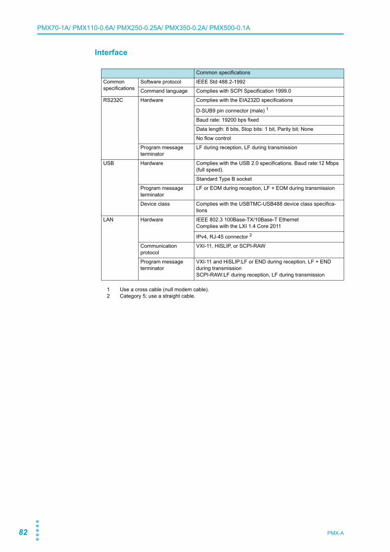
82 PMX-A
PMX70-1A/ PMX110-0.6A/ PMX250-0.25A/ PMX350-0.2A/ PMX500-0.1A
Interface
Common specifications
Common specifications
Software protocol IEEE Std 488.2-1992
Command language Complies with SCPI Specification 1999.0
RS232C Hardware Complies with the EIA232D specifications
D-SUB9 pin connector (male) 1
1 Use a cross cable (null modem cable).
Baud rate: 19200 bps fixed
Data length: 8 bits, Stop bits: 1 bit, Parity bit: None
No flow control
Program message terminator
LF during reception, LF during transmission
USB Hardware Complies with the USB 2.0 specifications. Baud rate:12 Mbps (full speed).
Standard Type B socket
Program message terminator
LF or EOM during reception, LF + EOM during transmission
Device class Complies with the USBTMC-USB488 device class specifica-tions
LAN Hardware IEEE 802.3 100Base-TX/10Base-T EthernetComplies with the LXI 1.4 Core 2011
IPv4, RJ-45 connector 2
2 Category 5; use a straight cable.
Communication protocol
VXI-11, HiSLIP, or SCPI-RAW
Program message terminator
VXI-11 and HiSLIP:LF or END during reception, LF + END during transmissionSCPI-RAW:LF during reception, LF during transmission

PMX-A 83
PMX70-1A/ PMX110-0.6A/ PMX250-0.25A/ PMX350-0.2A/ PMX500-0.1A
Spec
ifica
tions
6
General specifications
PMX70-1A PMX110-0.6A PMX250-0.25A PMX350-0.2A PMX500-0.1A
Weight (main unit only) Approximately 6 kg (13.23 lb)
Dimensions See the outline drawing
Environ-mental conditions
Operating environment Indoor use, overvoltage category II
Operating temperature 0 °C to +40 °C (32 °F to +104 °F)
Operating humidity 20 %rh to 85 %rh (no condensation)
Storage temperature −25 °C to +70 °C (−13 °F to +158 °F)
Storage humidity 90 %rh or less (no condensation)
Altitude Up to 2000 m
Cooling method Forced air cooling using fan
Grounding polarity Negative grounding or positive grounding possible
Isolation voltage ±550 Vdc
With-stand voltage
Between input and FG No abnormalities at 1500 Vac for 1 minute
Between input and output No abnormalities at 2100 Vac for 1 minute
Between output and FG No abnormalities at 2000 Vdc for 1 minute
Insulation resistance
Between input and FG 1000 Vdc, 30 MΩ or more
Between input and output 1000 Vdc, 30 MΩ or more
Between input and output 1000 Vdc, 30 MΩ or more
Electromagnetic compatibility 1 2 Complies with the requirements of the following directive and standards.EMC Directive 2014/30/EUEN 61326-1 (Class A3)
EN 55011 (Class A3, Group 14)EN 61000-3-2EN 61000-3-3
Applicable under the following conditionsThe maximum length of all cabling and wiring connected to the PMX-A must be less than 3 m.
Safety 1 Complies with the requirements of the following directive and standard. Low Voltage Directive 2014/35/EU2
EN 61010-1 (Class I5, Pollution degree 26)
Accesso-ries
Power cord 1 pc.
Packing list 1 copy
Quick reference Japanese:1 copy, English:1 copy, Chinese:1 copy
Safety precautions 1 copy
CD-ROM 1 disc
1 Does not apply to specially ordered or modified PMX-As.2 Limited to products that have the CE mark on their panels.
CE mark does not apply unless you use a USB cable with a ferrite core. [Kikusui-recommended cable: Elecom U2C-BF seriesUSB cable with a ferrite core, less than 3 m]
3 This is a Class A equipment. The PMX-A is intended for use in an industrial environment. This product may cause interferenceif used in residential areas. Such use must be avoided unless the user takes special measures to reduce electromagneticemissions to prevent interference to the reception of radio and television broadcasts.
4 This is a Group 1 equipment. The PMX-A does not generate and/or use intentionally radio-frequency energy, in the from of electromagnetic radiation, inductive and/or capacitive coupling, for the treatment of material or inspection/analysis purpose.
5 This is a Class I equipment. Be sure to ground the PMX-A's protective conductor terminal. The safety of this product is only guaranteed when the product is properly grounded.
6 Pollution is addition of foreign matter (solid, liquid or gaseous) that may produce a reduction of dielectric strength or surface resistivity. Pollution Degree 2 assumes that only non-conductive pollution will occur except for an occasional temporary con-ductivity caused by condensation.

84 PMX-A
PMX70-1A/ PMX110-0.6A/ PMX250-0.25A/ PMX350-0.2A/ PMX500-0.1A
Dimensions
PMX-A series outline drawing Unit: mm (inch)
70 (2.7
6)
57 (2.24) 230 (9.06)
18.5
(0.7
3)18
.5(0
.73)
MAX355 (13.98)
315 (12.40)MAX25(0.98)107 (4.21)
MAX
150
(5.9
1)
MAX
15(0
.59)
124
(4.8
8)
Diameter: 21 x 4(Rubber foot diameter)
M3 screw holes x 4Max. screw insertion depth: 4 mm (0.16 inches)

AppendixA OptionsB Troubleshooting

86 PMX-A
A Options
The PMX-A series has the following options.For information about options, contact your Kikusui agent or distributor.
Rack mount option
Remove the handle and rubber feet before you mount the PMX-A to a rack.For information on rack mounting, see the KRA3 or KRA150 operation manual.To support the main unit, attach an angle support to it that is appropriate for the rack.We recommend that you keep all pieces that you have removed from the PMX-A. You willneed these pieces if you remove the PMX-A from the rack.If you remove the PMX-A from the rack, re-attach the original rubber feet.
Name Model Note
Rack mount adapter KRA3 For EIA inch racks
KRA150 For JIS millimeter racks
Blank panel KBP3-2 (1/2 width) For both EIA inch racksand JIS millimeter racksKBP3-4 (1/4 width)
BP191 (-M) 1
1 The “-M” at the end of the model name indicates a mesh type.
For EIA inch racks
BP1H (-M) 1 For JIS millimeter racks
149
(5.8
7)
100
(3.9
4)24
.5 (0
.96)
460 (18.11)480 (18.9)
260 (10.24)
KRA150
37.7
5 (1
.49)
57
(2.2
4)
132.
5 (5
.22)
460 (18.11)482 (18.98)
260 (10.24)
KRA3
Unit: mm (inches)

PMX-A 87
App
Removing the handle and feet
1 Unfasten the two M4 screws, and remove the entire handle.
2 Unfasten the four M3 screws, and remove the four rubber feet.
Connector kit OP01-PMX (749809-9 DB25)
p.44 A connector kit for connecting to the J1 connector toexternally control the PMX-A.
Terminal unit TU01-PMXA terminal unit for converting the J1 connector of thisproduct to the J2 connector of the Kikusui PMC-A SeriesRegulated DC Power Supply.
To reinstall the handle that has been removed, use screw locking agent (e.g., 1401B by ThreeBond International, Inc.) to prevent screws from loosening..
Four feet
Four M3 screws
Two M4 screws
Two bracketsHandle
See

88 PMX-A
B Troubleshooting
This section introduces troubleshooting measures. Typical symptoms are listed. Checkwhether any of the items listed below apply to your case. In some cases, the problem can besolved quite easily.
p.42 If none of the items apply to your case, we recommend that you initialize the PMX-A series toits factory default settings. If the remedy does not correct the problem, contact your Kikusuiagent or distributor..
The power does not turn on
No output is generated
See
Symptom Items to check Remedy
The PMX-A series does not operate when the POWER switch is turned on.
Is the power cord broken? Exchange the power cord with a new one. p.10
Is the power cord connected cor-rectly?
Yes Exchange the power cord with a new one.
No Connect the power cord correctly.
When the POWER switch is turned on, it takes time before the operation-ready screen appears.
Is the PMX-A series configured to use a DHCP server for the LAN interface?
If a DHCP server is not available or if the network environment is not in good condi-tion, it may take time for the PMX-A series to start. Configure the PMX-A series to not use a DHCP server in the CONFIG set-tings (CF30: oFF), or consult your network administrator.
p.37
Symptom Items to check Remedy
No output is generated even when the OUTPUT switch is turned on.
Is the output voltage set to 0 V and the output current set to 0 A?
Turn the knobs to set the output voltage and output current to the required values.
p.23
Are you using an external con-tact to turn output on and off?
Yes Use the external contact to turn output on. p.53
No Set the external control parameter for turn-ing output on and off to “off” (CF06: oFF).
p.36
Even when the PMX-A series is configured so that output is turned on at power-on, the output is turned off immediately after the power is turned on.
Has the overvoltage protection (OVP) function been activated?
Set the OVP value higher than the voltage setting.
p.28
Has the overheat protection (OHP) func-tion been activated?
The internal temperature is abnormally high. Check the operating conditions. After you have removed the cause of the abnor-mal temperature, turn the power switch on.
p.30
The air inlet (louver) may be clogged, or the fan may be broken. Check these items.
—
See
See

PMX-A 89
App
The output is unstable
The output ripple is large
Unable to perform panel operations
Symptom Items to check Remedy
When the output is on, turn-ing the VOLTAGE knob or CURRENT knob results in unstable output.
Is the operation mode switching from CV to CC or CC to CV?
Change the setting (output voltage or out-put current) that is limiting the output to a value greater than the present setting. If the setting is at maximum, you must use a power supply that has a larger output volt-age or current.
p.26
The output voltage or output current fluctuates.
Is the remote sensing feature turned on? When you are not using remote sensing, turn off the sensing switch.
p.18
Are both the CV and CC LEDs turned on? If the output is oscillating when you are using remote sensing, insert a capacitor across the load.The circuit may be malfunctioning. Imme-diately stop using the PMX-A series, and have it repaired.
p.18
Do the sensing cables or load cables have poor contact, or are the cables broken?
Turn the POWER switch off, and check the wiring.
p.16p.18
Does the load current have peaks, or is it pulse shaped?
The peak values may be exceeding the set constant current. Increase the set con-stant current or increase the current capacity.
p.13p.26
The output voltage is offset from the voltage that the PMX-A series was generat-ing when it was turned on.
Has 30 minutes passed since the power was turned on?
Warm up the PMX-A series for at least 30 minutes.
—
Symptom Items to check Remedy
The ripple sometimes becomes large.
Is the input voltage outside the range? Apply a voltage that is within the input volt-age range.
SPEC
The ripple increased when the PMX-A series was installed in a different loca-tion.
Is something nearby generating a strong magnetic or electrical field?
Take measures such as moving the PMX-A series away from the field sources or twisting the cables connected to the PMX-A series.
—
The output ripple is large during external control.
Is there a large amount of external voltage noise?
Take measures against noise. —
The ripple increased when the load cable was changed.
Are the remote sensing cables con-nected?
When you are not using remote sensing, disconnect the remote sensing cables.
p.18
Symptom Items to check Remedy
Unable to perform panel operations.
Is the LOCK LED lit? Release the panel operation lock. p.41
Is the REMOTE LED lit? To control the PMX-A series from the panel, press the LOCAL switch to switch to local mode.
p.41
Is the PMX-A series being controlled via the RS232C, USB, or LAN interface?
The PMX-A series does not switch to local mode even when the LOCAL switch is pressed.
Was a local lockout (llo) command sent through the communication interface?
Send the “SYST:LOC” communication command to clear the local lockout (llo) status. —
See
See
See

90 PMX-A
The ALARM LED lights when the OUTPUT switch is turned on
Unable to perform remote control
Symptom Items to check Remedy
The ALARM LED lights when the OUTPUT switch is turned on.
Is the OVP activation point set to a value less than the output voltage?
Set the OVP activation point to a value higher than the output voltage.
p.28
Is the OCP activation point set to a value less than the output current?
Set the OCP activation point to a value higher than the output current.
Is the remote sensing feature turned on? When you are not using remote sensing, turn off the sensing switch.
p.18
Set up the environment so that the voltage drop in each load cable is within the com-pensation voltage range (0.6 V for a single line).
p.18
Are the polarities of the remote sensing cables connected in reverse?
The polarities of the remote sensing cables may be connected in reverse, or the ends of the cables may be shorted. Check the load cables.
p.18
Are you using external control with a loose control cable?
Connect the cable correctly. p.44
Is the external voltage excessive during external control?
Apply the correct voltage. p.49p.51
Is the internal temperature too high? The overheat protection function (OHP) has been activated. Check the operating environment.
p.30
SPEC
The louver may be clogged, or the fan may be broken. Check these items. —
The ALARM LED lights when the load is changed.
Is a large external voltage, such as that of a battery load, being applied?
The overvoltage protection function (OVP) or the overcurrent protection function (OCP) may have been activated. Check these items.The PMX-A series may be overloaded. Check the load.
p.27
Is the actual output voltage higher than the set voltage that is displayed on the panel?
Is a special load connected? The PMX-A series may be overloaded. Check the load.
—
Symptom Items to check Remedy
Remote control through the communication interface cannot be performed.
Have you selected the communication interface that you want to use in the CON-FIG settings?
Select the remote control communication interface (CF20).
p.37
When the LAN interface is in use, the DHCP server’s automatic IP address assignment cannot be final-ized.
When the POWER switch is turned on, does the LAN interface display persist for more than 30 seconds?
A timeout may have occurred while the PMX-A series was waiting for a response from the DHCP server or because no response was received. Consult your net-work administrator.
p.11
When the LAN interface is in use, the IP address cannot be obtained from the DHCP server.
Is the LAN LED lit in orange or red? If it is lit in orange, the PMX-A series is waiting for a response from the DHCP server.If it turns red afterward, the PMX-A series may have timed out.Consult your network administrator.
p.37
See
See

PMX-A 91
Aalarm
clearing ......................................................... 27display .......................................................... 28occurrence .................................................... 27
alarm signal ............................................................. 27
CCC control setting .................................................... 36CC mode .................................................................. 24constant-current mode ............................................. 24constant-voltage mode ............................................ 24CV control setting .................................................... 36CV mode .................................................................. 24
DDHCP ....................................................................... 37Dimensions .............................................................. 84
Eexternal monitoring .................................................. 55
Ffactory default settings ............................................. 42firmware version ........................................................ 2front panel ................................................................. 6
Iinitialization .............................................................. 42IP address display ................................................... 38IP address, auto ....................................................... 37IP address, manual .................................................. 37
JJ1 connector pin arrangement ................................. 45
Kkey lock function ...................................................... 41
LLAN interface
resetting ........................................................ 38restart ........................................................... 38
MMAC address display ............................................... 38memory contents, display ........................................ 35
OOCP ......................................................................... 28
OHP ......................................................................... 30output on and off
external control ............................................. 36external control logic .................................... 36
output-on startup state ............................................. 36OVP ......................................................................... 28
Ppower-on status ....................................................... 35product ID display .................................................... 39protection function
overcurrent protection .................................. 28overheat protection ...................................... 30overvoltage protection .................................. 28
Rrear panel ................................................................. 8remote interface ....................................................... 37remote sensing ........................................................ 18
SSCPI communication error display .......................... 37settings, reset .......................................................... 35SHIFT ....................................................................... 3
Ttroubleshooting ........................................................ 88
Vvendor ID display ..................................................... 38version ....................................................................... 2
Index

92 PMX-A
This page has been intentionally left blank.


KIKUSUI ELECTRONICS CORP.
www.kikusui.co.jp/en
1-1-3 Higashiyamata, Tsuzuki-ku, Yokohama, 224-0023, JapanTel: +81-45-482-6353Fax: +81-45-482-6261