8.1 universal serial lnterface (uss) - sam себе plc...
TRANSCRIPT

10.2001 Communication / USS
Siemens AG 6SE7087-6QX60 (Version AE)SIMOVERT MASTERDRIVES Compendium Vector Control 8.1-1
8.1 Universal Serial lnterface (USS)
This documentation describes the application of the Universal SerialInterface Protocol (USS) for SIMOVERT MASTERDRIVES MC and VC.
The USS protocol is a simple serial data transfer protocol, defined bySiemens AG, which is fully tailored to the requirements of drivetechnology. A detailed description of the protocol specifications, thephysical interface, the bus structure as well as a definition of thetransferred net data for drive applications are documented in thespecification "Universal serial interface protocol USS protocol"(Order No. E20125-D0001-S302-A1).
Using the USS protocol, a user can establish a serial bus link betweena higher-level master system and several slave systems. Mastersystems can be, for example, PLCs or PCs. SIMOVERTMASTERDRIVES drive converters are always the slaves on the bussystem. Furthermore, SIMOVERT MicroMaster, SIMOVERT P 6SE21and 6RA23 and 6RA24 drive converters can be operated as slaves onthe USS bus.
The USS protocol allows the user to implement both automation taskswith cyclical telegram traffic (⇒ a fixed telegram length is necessary) aswell as visualization tasks. In this case, the protocol with variabletelegram length is advantageous, as texts and parameter descriptionscan be transferred in one telegram without chopping up the information.
Introduction
NOTE

Communication / USS 10.2001
6SE7087-6QX60 (Version AE) Siemens AG8.1-2 Compendium Vector Control SIMOVERT MASTERDRIVES
8.1.1 Protocol specification and bus structure
The USS protocol has the following significant features:
♦ Supports a multi-point-capable link, e.g. EIA RS 485 hardware or apoint-to-point link, e.g. EIA RS 232.
♦ Master-slave access technique
♦ Single-master system
♦ Maximum 32 nodes (max. 31 slaves)
♦ Operation with variable or fixed telegram length
♦ Simple, reliable telegram frames
♦ The same bus mode of operation as with the PROFIBUS(DIN 19245 Part 1)
♦ Data interface to the basic unit according to PROFILE variable-speed drives. This means that, when the USS is being used,information is transferred to the drive in the same way as with thePROFIBUS-DP.
♦ Can be used for start-up, service and automation
♦ PC-based service tools (e.g. SIMOVIS) for SIMOREG andSIMOVERT
♦ Can be easily implemented in customized systems
8.1.1.1 Protocol specification
The USS protocol defines an access technique according to themaster-slave principle for communications via a serial bus. The point-to-point link is included as a sub-quantity.
One master and a maximum of 31 slaves can be connected to the bus.The individual slaves are selected by the master using an addresscharacter in the telegram. A slave can never transmit without first beinginitiated by the master so that direct information transfer betweenindividual slaves is not possible. Communication takes place in the half-duplex mode.
The master function cannot be transferred (single-master system).
The following illustration shows a bus configuration using drivetechnology as an example.
Features
Introduction

10.2001 Communication / USS
Siemens AG 6SE7087-6QX60 (Version AE)SIMOVERT MASTERDRIVES Compendium Vector Control 8.1-3
SIMOVERTMASTERDRIVES
"Slave"
Higher-levelcomputer
"Master"
SIMOVERTMASTERDRIVES
"Slave"
SIMOVERTMASTERDRIVES
"Slave"
SIMOVERTMASTERDRIVES
"Slave"
Fig. 8.1-1 Serial linking of SIMOREG/SIMOVERT drive converter (slaves) with ahigher-level computer as the master
Each telegram begins with the start character STX (= 02 hex), followedby the length information (LGE) and the address byte (ADR). The netcharacters then follow. The telegram is terminated by the BCC (BlockCheck Character).
STX LGE ADR 1. 2. n BCC
Net characters
Fig. 8.1-2 Telegram structure
For single-word data (16 bit) in the net data block (= net characterblock), the high byte (first character) is always sent and then the lowbyte (second character). The same applies to double-word data: thehigh word is sent first followed by the low word.
The protocol does not identify tasks in the net characters. The contentsof the net data for SIMOVERT MASTERDRIVES drive converters isdealt with in Section 8.1.3.
Information is coded as follows:
♦ STX (start of text)ASCII characters: 02 hexadecimal
♦ LGE (telegram length)1 byte, contains the telegram length
♦ ADR (address byte)1 byte, contains the slave address and the telegram type(binary coded)
♦ Net charactersEach one byte, contents are task-dependent
♦ BCC1 byte, Block Check Character
Telegram structure
Data coding

Communication / USS 10.2001
6SE7087-6QX60 (Version AE) Siemens AG8.1-4 Compendium Vector Control SIMOVERT MASTERDRIVES
In the address byte, information other than the node number is coded:
The individual bits in the address byte are assigned as follows:
= 0: No mirror telegram
Bit No. 7 6 5 4 3 2 1 0
STX LGE ADR 1. 2. n BCC
Net characters
Slave nodes No. 0 to 31
= 1: Mirror telegram
= 1: Special telegram (for an explanation, see below)= 0: Standard; bits 0 to 6 are valid and must be evaluated
= 0: No broadcast= 1: Broadcast, address bits (No. 0 to 4) are not evaluated
Fig. 8.1-3 Assignment of the address byte (ADR)
The master ensures cyclical telegram data transfer. The masteraddresses all of the slave nodes one after the other with a tasktelegram. The addressed nodes respond with a reply telegram. Inaccordance with the master-slave procedure, the slave, after receivingthe task telegram, must send the reply telegram to the master beforethe master can address the next slave node.
The sequence of the addressed slave nodes can be specified, forexample, by entering the node numbers (ADR) in a circulating list(polling list) in the master. If it is necessary to address several slaves ina faster cycle than the other slaves, their node number can occurseveral times in the circulating list. A point-to-point link can beimplemented by means of the circulating list, in which case only onenode is entered into the circulating list.
Assigning theaddress byte (ADR)
Data transferprocedure
Handling datatransfer

10.2001 Communication / USS
Siemens AG 6SE7087-6QX60 (Version AE)SIMOVERT MASTERDRIVES Compendium Vector Control 8.1-5
1 3 57 21 0
Master
0
1
3
5
0
7
2 1
1
3
5
0
1
0
1
7
2 1
Example of configuration
Circulating list in the master
SIMOVERT MASTERDRIVES with the addresses 0, 1, 3, 5, 7 and 21
Nodes 0 and 1 are signalled twice as often as others
Fig. 8.1-4 Circulating list
The length of a cycle time is determined by the time needed for thesequential occurrence of data exchange with the individual nodes.
0 0 1 1 0 0 t
Cycle time
Telegram run time for reply from node 1
Reply delay time from node 1
Telegram run time for task for node 1
Processing time in the master
Fig. 8.1-5 Cycle time
Due to inconstant reply delay and processing times, the cycle time isnot fixed.
Cycle time
Communication / USS 10.2001
6SE7087-6QX60 (Version AE) Siemens AG8.1-6 Compendium Vector Control SIMOVERT MASTERDRIVES
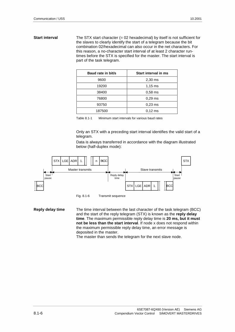
The STX start character (= 02 hexadecimal) by itself is not sufficient forthe slaves to clearly identify the start of a telegram because the bitcombination 02/hexadecimal can also occur in the net characters. Forthis reason, a no-character start interval of at least 2 character run-times before the STX is specified for the master. The start interval ispart of the task telegram.
Baud rate in bit/s Start interval in ms
9600 2,30 ms
19200 1,15 ms
38400 0,58 ms
76800 0,29 ms
93750 0,23 ms
187500 0,12 ms
Table 8.1-1 Minimum start intervals for various baud rates
Only an STX with a preceding start interval identifies the valid start of atelegram.
Data is always transferred in accordance with the diagram illustratedbelow (half-duplex mode):
STX LGE ADR 1. n BCC
STX LGE ADR 1. BCCBCC
STX
Start pause
Master transmits Slave transmits
Start pause
Reply delaytime
Fig. 8.1-6 Transmit sequence
The time interval between the last character of the task telegram (BCC)and the start of the reply telegram (STX) is known as the reply delaytime. The maximum permissible reply delay time is 20 ms, but it mustnot be less than the start interval. If node x does not respond withinthe maximum permissible reply delay time, an error message isdeposited in the master.The master than sends the telegram for the next slave node.
Start interval
Reply delay time

10.2001 Communication / USS
Siemens AG 6SE7087-6QX60 (Version AE)SIMOVERT MASTERDRIVES Compendium Vector Control 8.1-7
8.1.1.2 Bus structure
The data transfer medium and the physical bus interface are essentiallydetermined by what the bus system is used for.
The physical interface of the USS protocol is based on the"Recommended Standard RS-485". For point-to-point links, a sub-quantity of EIA RS-232 (CCITT V.24), TTY (20 mA current loop) orfiber-optic cables can be used as the physical interface.
The interfaces for SIMOVERT MASTERDRIVES are always RS 485with 2-wire cable.
Exception: Either RS 485 or RS 232 can be connected at the 9-pinSUB D socket connector on the PMU (operator controland parameterizing unit) of the basic units.
This section describes how a USS field bus has to be structured inorder to ensure reliable data transfer via the transfer medium instandard applications. Under special conditions of use, additionalfactors must be taken into account which require further measures orrestrictions that are not described in this document.
The USS bus is based on a linear topology without branches.
Both ends of the line terminate at a node.
The maximum cable length and therefore the maximum distancebetween the master and the last slave is limited by the characteristicsof the cable, the ambient conditions and the data transfer rate. With adata transfer rate of < 100 kbit/s, a maximum length of 1200 m ispossible.
The number of nodes is limited to a maximum of 33(1 master, 32 slaves).
MASTER
SLAVE SLAVEMaximum 32 slaves
Last nodeFirst node
SLAVE
Fig. 8.1-7 USS bus topology
NOTICE
Topology

Communication / USS 10.2001
6SE7087-6QX60 (Version AE) Siemens AG8.1-8 Compendium Vector Control SIMOVERT MASTERDRIVES
The two ends of a bus line (first node and last node) must beterminated with bus terminating networks.Point-to-point connections are handled just like bus connections. Onenode has the master function and the other has the slave function.
Data is transferred in accordance with Standard EIA 485. RS 232 canbe used for point-to-point links. Data transfer is always half-duplex −i.e. alternating between transmitting and receiving − and it must becontrolled by the software. The half-duplex technique allows the samecables to be used for both data-transfer directions. This permits simpleand inexpensive bus cabling, operation in environments subject tointerference and a high data transfer rate.
A shielded, twisted two-wire cable is used as the bus cable.
Conductor diameter ∅ 2 × ≈ 0,5 mm2
Conductor ≥ 16 x ≤ 0,2 mm
Lay ratio ≥ 20 twists / m
Overall shield Braided, tin-plated copper wire, diameter ∅ ≥ 1,1 mm2
85 % optical coverage
Overall diameter∅ ≥ 5 mm
External sheath Depending on the requirements regarding flameretardation, deposits after burning etc.
Table 8.1-2 Structural data
All information should only be considered as a recommendation.Deviations or different measures may be required depending on theparticular requirements, the specific application and the conditions onsite.
Cable resistance (20°C) ≤ 40 Ω/km
Insulation resistance (20°C) ≥ 200 MΩ/km
Operating voltage (20°C) ≥ 300 V
Test voltage (20°C) ≥ 1500 V
Temperature range -40 °C ≤ T ≥ 80 °C
Load capability ≥ 5 A
Capacitance ≤ 120 pF/m
Table 8.1-3 Thermal and electrical characteristics
Data transfertechnology
Cablecharacteristics
NOTE
Thermal andelectricalcharacteristics

10.2001 Communication / USS
Siemens AG 6SE7087-6QX60 (Version AE)SIMOVERT MASTERDRIVES Compendium Vector Control 8.1-9
Single bending: ≤ 5 x outer diameter
Repeated bending: ≤ 20 x outer diameter
1. Standard, without any special requirements:Two-core, flexible, shielded conductor in accordance with VDE 0812,with colored PVC sheath.PVC insulation resistant to oil and petroleum products.
♦ Type: LIYCY 2 x 0,5 mm2
e.g. Metrofunk Kabel-Union GmbHPostfach 41 01 09, 12111 BerlinTel 030-831 40 52, Fax: 030-792 53 43
2. Halogen-free cable (no hydrochloric acid is generated when thecable burns):Halogen-free, highly flexible, resistant to extreme heat and cold.Sheath manufactured from a special ASS silicon-based composite.
♦ Type: ASS 1 x 2 x 0,5 mm2
e.g. Metrofunk Kabel-Union GmbHPostfach 41 01 09, 12111 BerlinTel 030-831 40 52, Fax: 030-792 53 43
3. Recommended if halogen-free and silicon-free cables are required:
♦ Type: BETAflam G-M/G-G-B1 flex. 2 x 0,5 mm2
e.g. Studer-Kabel-AG, CH 4658 Däniken
The cable length is dependent on the data transfer rate and the numberof connected nodes. The following cable lengths are possible given thespecified cable characteristics:
Data transfer rate Max. number of nodes Max. cable length
9.6 kbit/s 32 1200 m
19.2 kbit/s 32 1200 m
93.75 kbit/s 32 1200 m
187.5 kbit/s 30 1000 m
Table 8.1-4 Cable lengths
Mechanicalcharacteristics
Recommendations
Cable lengths

Communication / USS 10.2001
6SE7087-6QX60 (Version AE) Siemens AG8.1-10 Compendium Vector Control SIMOVERT MASTERDRIVES
8.1.2 The structure of net data
Information which, for example, a SIMATIC S5 control unit (= master)sends to a drive (= slave) or the drive sends to the control unit is placedin the net-data area of each telegram.
8.1.2.1 General structure of the net-data block
The net-data block is divided into two areas:
♦ the PKW (parameter ID value) range
♦ the PZD (process data) range
The structure of the net data in the USS-protocol telegram is shownbelow.
Protocol frame
STX LGE ADR
Net data
Parameter(PKW)
Process data(PZD)
BCC
PKW: Parameter ID value(parameter area)
PZD: Process data(process-data area)
♦ The PKW area relates to the handling of the parameter ID value(PKW) interface. The PKW interface is not a physical interface but amechanism which handles parameter transfer between twocommunication partners (e.g. control unit and drive). This involves,for example, reading and writing parameter values and readingparameter descriptions and associated texts.All tasks which are performed via the PKW interface essentiallyinvolve operator control and visualization, service and diagnosis.
♦ The PZD area contains the signals required for the automationsystem:
• Control word(s) and setpoint(s) from the master to the slave
• Status word(s) and actual value(s) from the slave to the master.
PKW area PZD area
PKE IND PKW elements PZD1 • • • PZD16
Variable length Variable length
The two areas together make up the net data block. This structureapplies to telegrams from the master to the slave and vice versa.
Introduction
Telegram structure
Structure of thePKW and PZD areas

10.2001 Communication / USS
Siemens AG 6SE7087-6QX60 (Version AE)SIMOVERT MASTERDRIVES Compendium Vector Control 8.1-11
8.1.2.2 PKW area
With the help of the PKW mechanism, the following tasks can beperformed via any serial interface with the USS protocol:
♦ Reading and writing parameters in the basic unit and, if available,parameters on a technology board, e.g. T100
♦ Reading the description of a parameter(applies to parameters of the basic unit and of technology boards)
♦ Reading of texts assigned to the indices of an indexed parameter.(Applies to parameters of the basic unit and of the technologymodules.)
♦ Reading of texts assigned to the values of a parameter.(Applies to parameters of the basic unit and of the technologymodules.)
The PKW area can be varied. Depending on the particular requirement,3-word, 4-word or variable word lengths can be parameterized.
The following is an example of a structure when access (write/read) ismade to single-word (16 bit) parameter values:
1st word 2nd word 3rd word
PKE IND PWE1
Parameter ID Index Parameter value 1
The PKW area must be permanently set to 3 words at the master andthe slave. This setting is made during start-up and should not be alteredany more during bus operation.
The following is an example of a structure when access (write/read) ismade to double-word (32 bit) parameter values:
1st word 2nd word 3rd word 4th word
PKE IND PWE1 PWE2
High-Word Low Word
Parameter ID Index Parameter value (double word)
Parameterization to a fixed length of 4 words applies to telegrams fromthe master to the slave and from the slave to the master. The settingmust be made both at the master and at the slave and can no longer bealtered during bus operation.
Settings in the PKWarea
PKW areaparameterized for 3words
PKW areaparameterized to 4words

Communication / USS 10.2001
6SE7087-6QX60 (Version AE) Siemens AG8.1-12 Compendium Vector Control SIMOVERT MASTERDRIVES
1st word 2nd word 3rd word 4th word (m+2) word
PKE IND PWE1 PWE2 • • • PWEm
With:
♦ 1 word ≤ m ≤ 110 words (maximum) when 16 PZD words(maximum) are contained in the net data block.
♦ 1 word ≤ m ≤ 126 words (maximum) when there is no PZD.
Telegram data transfer with variable telegram length means that theslave responds to a telegram from the master with a telegram whoselength does not have to be the same length as the telegram from themaster to the slave. The length of elements PEW 1 to PWE m in thereply telegram and what is contained in them depends on the taskissued by the master. Variable length means that only the number ofwords necessary to pass on the appropriate information is transferred.The minimum length, however. is always 3 words.
If a slave, for example, transfers a parameter value which is a 16-bitquantity (e.g. the output voltage in parameter r003), then only 3 wordsof the PKW area are sent in the telegram from the slave to the master.With regard to the MASTERDRIVES MC/VC for example, if the currentspeed (parameter r002) is to be read, the PKW area in the telegramfrom the slave to the master is 4 words long since the speed is storedas a 32-bit quantity in parameter r002. Variable word-lengthparameterization is mandatory if, for example, all values are to be readat once from an "indexed" parameter or if the parameter description ofa parameter is to be partially or completely read. This setting to variableword-length is made during start-up.
Do not use a variable word length if a SIMATIC S5 or SIMATIC S7 isthe master.
PKW areaparameterized withvariable word length
NOTICE

10.2001 Communication / USS
Siemens AG 6SE7087-6QX60 (Version AE)SIMOVERT MASTERDRIVES Compendium Vector Control 8.1-13
Parameter ID 1st word
Bit No.: 15 12 11 10 0
AK SPM PNU
Parameter index 2nd word
Bit No.: 15 8 7 0
Index High Index Low
Parameter value
Parameter value High (PWE1) 3rd word
Parameter value Low (PWE2) 4th word
AK: Task or reply ID
SPM: Toggle bit for processing of parameter-change reports
PNU: Parameter number
The PKW area is transferred in increasing order, always starting withthe 1st word.
Structure of theparameter area(PKW)
NOTE

Communication / USS 10.2001
6SE7087-6QX60 (Version AE) Siemens AG8.1-14 Compendium Vector Control SIMOVERT MASTERDRIVES
The parameter ID (PKE) is always one word (16-bit quantity).
Bits 0 to 10 (PNU), together with bit 15 of the parameter index, make upthe number of the desired parameter (see parameter list).
Number PKE: Bits 0 to 10(PNU)
Index: Bit 15
1 - 999 1 - 999 0 Basic unit
2000 - 2999 0 - 999 1 Basic unit
1000 - 1999 1000 - 1999 0 Technology module
3000 - 3999 1000 - 1999 1 Technology module
Bit 11 (SPM) is the toggle for parameter-change reports.MASTERDRIVES do not support parameter change reports.
Bits 12 to 15 (AK) contain the task or reply ID.
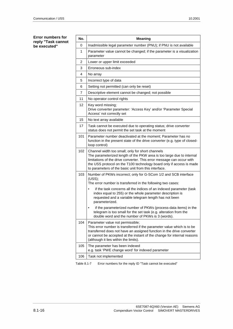
The task IDs are sent in the telegram from the master to the slave. Themeaning of the IDs is given in Table 8.1-5. Correspondingly, the replyIDs are transferred at this position in the telegram from the slave to themaster (see Table 8.1-6). Depending on the task ID, only certain replyIDs are possible. If the reply ID is 7 (task cannot be executed), then anerror number is entered in parameter value 2 (PWE2). The errornumbers are shown in Table 8.1-7.
Task ID Meaning Reply ID
positive negative
0 No task 0 7 or 8
1 Request parameter value 1 or 2 ↑
2 Change parameter value (word) 1
3 Change parameter value (double word) 2
4 Request descriptive element 1 3
6 Request parameter value (array)1 4 or 5
7 Change parameter value (array, word)2 4
8 Change parameter value (array, double word)2 5
9 Request the number of array elements 6
10 Reserved -
11 Change parameter value (array, double word) and save in EEPROM 2 5
12 Change parameter value (array, word) and save in EEPROM 2 4
13 Change parameter value (double word) and save in EEPROM 2
14 Change parameter value (word) and save in EEPROM 1 ↓
15 Read or change text (only supported via OP or SIMOVIS) 15 7 or 8
1 The required element of the parameter description is specified in IND (2nd word)2 The required element of the indexed parameter is specified in IND (2nd word)
Table 8.1-5 Task IDs (master -> drive converter)
Parameter ID (PKE),1st word

10.2001 Communication / USS
Siemens AG 6SE7087-6QX60 (Version AE)SIMOVERT MASTERDRIVES Compendium Vector Control 8.1-15
Reply ID Meaning
0 No reply
1 Transfer parameter value (word)
2 Transfer parameter value (double word)
3 Transfer descriptive element 1
4 Transfer parameter value (array, word) 2
5 Transfer parameter value (array, double word) 2
6 Transfer the number of array elements
7 Task cannot be executed (with error number)
8 No control/change rights for the PKW interface
9 Parameter change report (word)
10 Parameter change report (double word)
11 Parameter change report (array, word) 2
12 Parameter change report (array, double word) 2
13 Reserved
14 Reserved
15 Transfer text
* For table footnotes 1 and 2, see Table 8.1-5
Table 8.1-6 Reply IDs (drive converter -> master)
Source for the ON/OFF1 command (control word1, bit 0):P554 (=22A hex) Change parameter value (array, word) and save inthe EEPROM.
Parameter ID (PKE) 1st word
Bit No.: 15 12 11 10 0AK SPM PNU
1 1 0 0 0 0 1 0 0 0 1 0 1 0 1 0 Binary valueC 2 2 A HEX value
♦ Bits 12 to 15: Value = 12 (= "C" hex); change parameter value (array, word) and savein the EEPROM
♦ Bits 0 to 11: Value = 554 (= "22A" hex); parameter number with a set change-reportbit
Example
Communication / USS 10.2001
6SE7087-6QX60 (Version AE) Siemens AG8.1-16 Compendium Vector Control SIMOVERT MASTERDRIVES
No. Meaning
0 Inadmissible legal parameter number (PNU); if PNU is not available
1 Parameter value cannot be changed; if the parameter is a visualizationparameter
2 Lower or upper limit exceeded
3 Erroneous sub-index
4 No array
5 Incorrect type of data
6 Setting not permitted (can only be reset)
7 Descriptive element cannot be changed; not possible
11 No operator control rights
12 Key word missing;Drive converter parameter: ‘Access Key’ and/or ‘Parameter SpecialAccess’ not correctly set
15 No text array available
17 Task cannot be executed due to operating status; drive converterstatus does not permit the set task at the moment
101 Parameter number deactivated at the moment; Parameter has nofunction in the present state of the drive converter (e.g. type of closed-loop control)
102 Channel width too small; only for short channelsThe parameterized length of the PKW area is too large due to internallimitations of the drive converter. This error message can occur withthe USS protocol on the T100 technology board only if access is madeto parameters of the basic unit from this interface.
103 Number of PKWs incorrect; only for G-SCom 1/2 and SCB interface(USS);The error number is transferred in the following two cases:
• if the task concerns all the indices of an indexed parameter (taskindex equal to 255) or the whole parameter description isrequested and a variable telegram length has not beenparameterized.
• if the parameterized number of PKWs (process-data items) in thetelegram is too small for the set task (e.g. alteration from thedouble word and the number of PKWs is 3 (words).
104 Parameter value not permissible;This error number is transferred if the parameter value which is to betransferred does not have an assigned function in the drive converteror cannot be accepted at the instant of the change for internal reasons(although it lies within the limits).
105 The parameter has been indexede.g. task ‘PWE change word’ for indexed parameter
106 Task not implemented
Table 8.1-7 Error numbers for the reply ID "Task cannot be executed"
Error numbers forreply "Task cannotbe executed"

10.2001 Communication / USS
Siemens AG 6SE7087-6QX60 (Version AE)SIMOVERT MASTERDRIVES Compendium Vector Control 8.1-17
The parameter ’SCom/SCB PKW #" P702:
♦ Minimum value: 0 (0 words)
♦ Maximum value: 127 (corresponds to: variable length)
♦ Permissible values for USS: 0, 3, 4 and 127.
If a change task with a PWE which is not 0, 3, 4 or 127 is issued to thedrive converter, the reply is "Task cannot be executed" with error value104.
The low-part of the index (bit 0 to 7), depending on the task, describesa definite element:
♦ desired array element in the case of indexed parameters,
♦ desired element of the parameter description,
♦ for indexed parameters with "index text": desired index text,
♦ for non-indexed parameters with "selection text": desired selectiontext.
Bits 8 to 14 must as a general rule all be equal to 0. The onlyexceptions are those parameters that are indexed and possess"selection texts". In this case bit 9 must be set to 1 to clearly identify thedesired text type. The low-part then defines the desires "selection text".
Bit 15, together with bits 0 to 10 in the PKE, serves to constitute thenumber of a parameters (see Parameter coding).
With regard to the task "Request (parameter element) descriptiveelement" (= AK 4) or tasks relating to the reading/writing of indexedparameters (= arrays), index value 255 has a special significance:
Task ID Meaning
4 The complete (parameter) description is requested
6 Request all values of the indexed parameterThis task can generate error message 102.
7, 8, 11or 12
All values of the indexed parameter are to be changed.These tasks can generate error message 102.
Table 8.1-8 Tasks with index value 255
ExampleError message 104
Parameter index(IND) 2nd word
Special significanceof index value 255(low-part)
Communication / USS 10.2001
6SE7087-6QX60 (Version AE) Siemens AG8.1-18 Compendium Vector Control SIMOVERT MASTERDRIVES
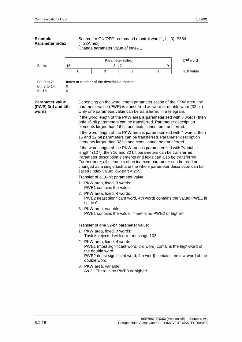
Source for ON/OFF1 command (control word 1, bit 0): P554(= 22A hex)Change parameter value of index 1.
Parameter index 2nd word
Bit No.: 15 8 7 0
0 0 0 1 HEX value
Bit 0 to 7:Bit 8 to 14:Bit 15:
Index or number of the descriptive element00
Depending on the word length parameterization of the PKW area, theparameter value (PWE) is transferred as word or double word (32 bit).Only one parameter value can be transferred in a telegram.
If the word length of the PKW area is parameterized with 3 words, thenonly 16 bit parameters can be transferred. Parameter descriptionelements larger than 16 bit and texts cannot be transferred.
If the word length of the PKW area is parameterized with 4 words, then16 and 32 bit parameters can be transferred. Parameter descriptionelements larger than 32 bit and texts cannot be transferred.
If the word length of the PKW area is parameterized with "Variablelength" (127), then 16 and 32 bit parameters can be transferred.Parameter description elements and texts can also be transferred.Furthermore, all elements of an indexed parameter can be read orchanged as a single task and the whole parameter description can becalled (index value: low-part = 255).
Transfer of a 16-bit parameter value:
1. PKW area, fixed, 3 words:PWE1 contains the value
2. PKW area, fixed, 4 words:PWE2 (least significant word, 4th word) contains the value; PWE1 isset to 0.
3. PKW area, variable:PWE1 contains the value. There is no PWE2 or higher!
Transfer of one 32-bit parameter value:
1. PKW area, fixed, 3 words:Task is rejected with error message 103.
2. PKW area, fixed, 4 words:PWE1 (most significant word; 3rd word) contains the high-word ofthe double wordPWE2 (least significant word; 4th word) contains the low-word of thedouble word.
3. PKW area, variable:As 2.; There is no PWE3 or higher!
ExampleParameter index
Parameter value(PWE) 3rd and 4thwords

10.2001 Communication / USS
Siemens AG 6SE7087-6QX60 (Version AE)SIMOVERT MASTERDRIVES Compendium Vector Control 8.1-19
Source for the ON/OFF1 command (control word 1, bit 0): P554(= 22A hex)Change parameter value of index 1 to the value 2100 (hex).
Parameter valueBit No.: 31 24 23 16 3rd word, PWE1
(hex)
0 0 0 0
Bit No.: 15 8 7 0 4th word, PWE2(hex)
2 1 0 0
Bit 0 to 15:Bit 16 to 31:
Parameter value for 16-bit parameter or low component for 32-bit parameterValue = 0 for 16-bit parameter or high component for 32-bit parameter
8.1.2.3 Process-data area (PZD)
In this area, process data are continually exchanged between themaster and slaves. The process data to be exchanged with a slave isconfigured at the start of communications. The setpoint for the currentis to be transferred to slave x in the second PZD (= PZD2), forexample. This setting is fixed for the whole procedure of data transfer.
PZD1-PZD16 = Process data(= control / status word(s) and setpoint(s) / actual value(s))
The control/status word(s), setpoint(s) and actual value(s) required forthe automation system are transferred in this area.
The length of the PZD area is determined by the number of PZDelements and their size (e.g. word, double word). In contrast to thePKW area, which can be variable, the length of this area (master andslaves) must always be agreed on between the communicationpartners. The maximum number of PZD words per telegram is limited to16 words. If only PKW data is to be transferred in the net data block,the number of PZDs may even be 0!
In PZD1, control word 1 or status word 1 is always transferred,depending on the direction of data transfer and, in PZD2, the mainsetpoint or the main actual value is always transferred, againdepending on the direction of data transfer. In the subsequent processdata areas PZD3 to PZDn, additional setpoints and actual values aresent. For SIMOVERT MASTERDRIVES, control word 2 or status word2, if necessary, is transferred in PZD4.
1 word 1 word 1 word 1 word
PZD1 PZD2 PZD3 • • • PZD16
Maximum 16 wordsMinimum 0 words, i.e. no PZD area in the net data block
PZDn is always transferred before PZDn+1 on the USS bus.
ExampleParameter value
Structure of the PZDarea
NOTE
Communication / USS 10.2001
6SE7087-6QX60 (Version AE) Siemens AG8.1-20 Compendium Vector Control SIMOVERT MASTERDRIVES
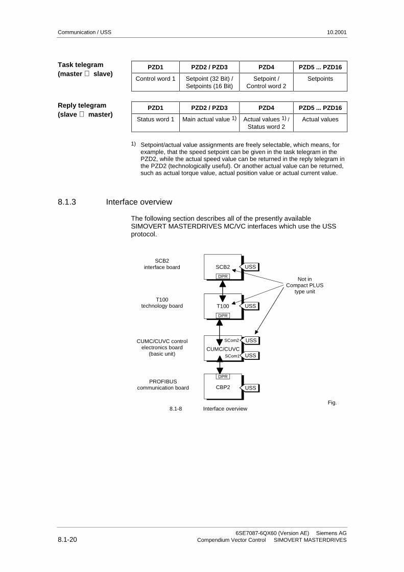
PZD1 PZD2 / PZD3 PZD4 PZD5 ... PZD16
Control word 1 Setpoint (32 Bit) /Setpoints (16 Bit)
Setpoint /Control word 2
Setpoints
PZD1 PZD2 / PZD3 PZD4 PZD5 ... PZD16
Status word 1 Main actual value 1) Actual values 1) /Status word 2
Actual values
1) Setpoint/actual value assignments are freely selectable, which means, forexample, that the speed setpoint can be given in the task telegram in thePZD2, while the actual speed value can be returned in the reply telegram inthe PZD2 (technologically useful). Or another actual value can be returned,such as actual torque value, actual position value or actual current value.
8.1.3 Interface overview
The following section describes all of the presently availableSIMOVERT MASTERDRIVES MC/VC interfaces which use the USSprotocol.
SCB2 USS
DPR
USS
USS
DPR
T100
CUMC/CUVC
USSSCom2
SCom1
USSCBP2PROFIBUS
communication board
DPR
SCB2interface board
T100technology board
CUMC/CUVC controlelectronics board
(basic unit)
Not in Compact PLUS
type unit
Fig.8.1-8 Interface overview
Task telegram(master ⇒ slave)
Reply telegram(slave ⇒ master)

10.2001 Communication / USS
Siemens AG 6SE7087-6QX60 (Version AE)SIMOVERT MASTERDRIVES Compendium Vector Control 8.1-21
In the SIMOVERT MASTERDRIVES MC series, the control electronicsboard, CUMC (Control Unit Motion Control) or CUVC (Control UnitVector Control), is used. Depending on the type of basic unit, it has atleast one serial interface with the USS protocol. The following tableshows the available interfaces:
Board Number of interfaces Physical interface Baud rate[kBit/s]
CUMC inCompact PLUS unit
1 interface with USSprotocolDesignation: SCom1
RS485 / 2-wire at terminal strip X100orRS232 or RS485 / 2-wire at 9-pole SUB-Dsocket X103
max. 38.4
CUMC in Compact andchassis type unit
2 interfaces with USSprotocolDesignation: SCom1and SCom2
RS485 / 2-wire on terminal strip X103(SCom1 and SCom2)orRS232 or RS485 / 2-wire at 9-pole SUB-Dsocket X300 (SCom1)
max. 38.4
CUVC in Compact andchassis type unit
2 interfaces with USSprotocolDesignation: SCom1and SCom2
RS485 / 2-wire on terminal strip X101(SCom2)andRS232 or RS485 / 2-wire at 9-pole SUB-Dsocket X300 (SCom1)
max. 38.4
CUVP inCompact PLUS unit
2 interfaces with USSprotocolDesignation: SCom1and SCom2
RS485 / 2-wire on terminal strip X100(SCom2)andRS232 or RS485 / 2-wire at 9-pole SUB-Dsocket X103
max. 38.4
Table 8.1-9 Interfaces on the CU board
All the interfaces on the CU boards are non floating (not electricallyisolated).
The SCB2 (Serial Communications Board) is an expansion board of theSIMOVERT MASTERDRIVES. The board has a floating RS485interface. Either the peer-to-peer protocol or the USS protocol can beused at this interface.
The supplementary SCB2 board cannot be built into the CompactPLUS type of unit.
Board Number of interfaces Physical interface
SCB2 1 interface withUSS protocol
RS485 / 2-wire atterminal strip X128
Table 8.1-10 Interface on the SCB 2 board
For a more detailed description of the SCB 2, refer to the instructionmanual, "Serial Communication Board 2"(Order No.: 6SE7087-6CX84-0BD0).
Basic unit withCUMC/CUVC/CUVP
NOTICE
SCB 2supplementaryboard
NOTE
NOTE
Communication / USS 10.2001
6SE7087-6QX60 (Version AE) Siemens AG8.1-22 Compendium Vector Control SIMOVERT MASTERDRIVES
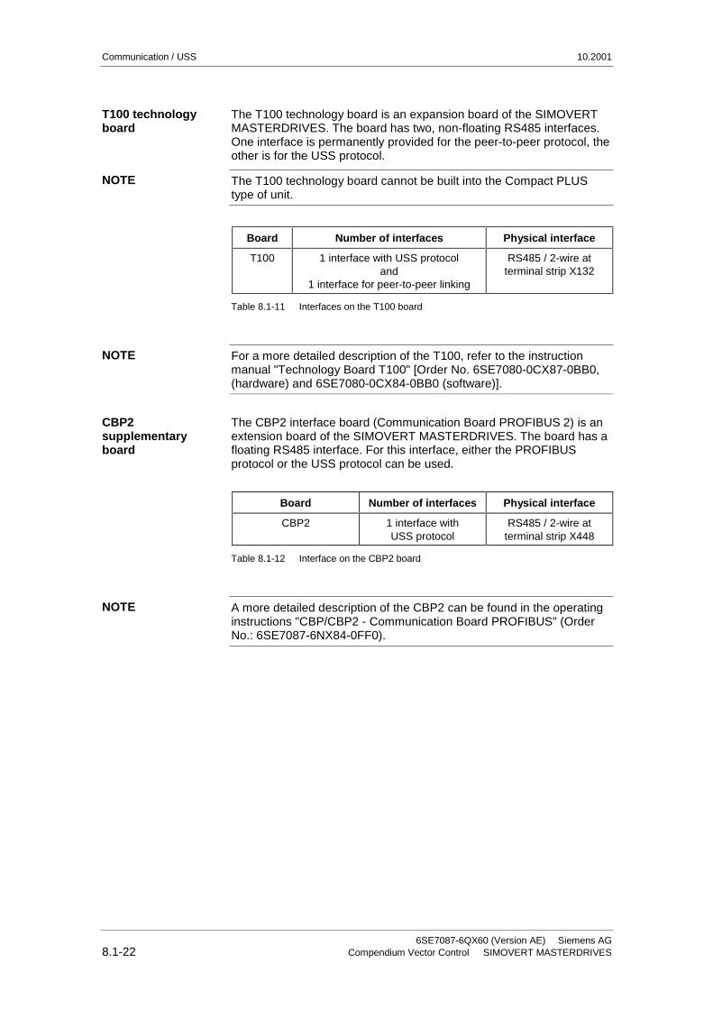
The T100 technology board is an expansion board of the SIMOVERTMASTERDRIVES. The board has two, non-floating RS485 interfaces.One interface is permanently provided for the peer-to-peer protocol, theother is for the USS protocol.
The T100 technology board cannot be built into the Compact PLUStype of unit.
Board Number of interfaces Physical interface
T100 1 interface with USS protocoland
1 interface for peer-to-peer linking
RS485 / 2-wire atterminal strip X132
Table 8.1-11 Interfaces on the T100 board
For a more detailed description of the T100, refer to the instructionmanual "Technology Board T100" [Order No. 6SE7080-0CX87-0BB0,(hardware) and 6SE7080-0CX84-0BB0 (software)].
The CBP2 interface board (Communication Board PROFIBUS 2) is anextension board of the SIMOVERT MASTERDRIVES. The board has afloating RS485 interface. For this interface, either the PROFIBUSprotocol or the USS protocol can be used.
Board Number of interfaces Physical interface
CBP2 1 interface withUSS protocol
RS485 / 2-wire atterminal strip X448
Table 8.1-12 Interface on the CBP2 board
A more detailed description of the CBP2 can be found in the operatinginstructions "CBP/CBP2 - Communication Board PROFIBUS" (OrderNo.: 6SE7087-6NX84-0FF0).
T100 technologyboard
NOTE
NOTE
CBP2supplementaryboard
NOTE
10.2001 Communication / USS
Siemens AG 6SE7087-6QX60 (Version AE)SIMOVERT MASTERDRIVES Compendium Vector Control 8.1-23
8.1.4 Connecting-up
♦ The equipment is operated at high voltages. They must be in a no-voltage condition (off load) during all connecting work!
♦ When work is being done on the unit, it must be in a no-loadcondition, i.e. it must be disconnected and locked-out from the linesupply.
♦ Only appropriately qualified personnel may work on or with theequipment.
♦ Death, severe bodily injury or considerable material damage mayresult if this warning is not complied with.
♦ Due to the DC link capacitors, there are still hazardous voltagelevels in the equipment for at least 5 minutes after it has beendisconnected from supply. There must therefore be a delay of atleast 5 minutes before the unit is opened.
♦ The power terminals and the control terminals can still carryhazardous voltage even when the motor has been shut down.
8.1.4.1 Bus cable connection
On SIMOVERT MASTERDRIVES, connection of the USS bus cabledepends on the control version and, in the case of MC units, it isdependent on the respective type of construction.
With the "Compact PLUS" type of unit, either terminal strip X100 orconnector X103 can be used to connect up the USS bus cable. Theexact pin assignment is given in the relevant operating instructions forthe basic unit.
With "Compact type" and "chassis type" units, the SCom1 and SCom2interfaces can be operated at the same time on terminal strip X103 withthe USS protocol. Alternatively, connector X300 can be used asSCom1. The exact pin assignment of terminal strip X103 or connectorX300 is given in the relevant operating instructions of the basic unit.
In the case of the "Compact type" and "chassis type" units, either theconnection of terminal strip X101 (SCom2) or X300 (SCom1) can beused to connect up the USS bus cable. The exact pin assignment ofterminal strip X101 or connector X300 is given in the relevant operatinginstructions of the basic unit.
In the case of the SCB2 board, the bus cable is terminated at terminalstrip X128. The exact pin assignment and other notes on terminationare given in the operating instructions for the SCB2.
In the case of the T100 technology board, the USS protocol isimplemented at interface 1. The bus cable is terminated at terminal stripX132. The exact pin assignment and other notes on termination aregiven in the hardware operating instructions for the T100.
DANGER
MC, VC,"Compact PLUS"type
MC,"Compact type" and"chassis type"
VC,"Compact type" and"chassis type"
SCB 2 board
Technology boardT100

Communication / USS 10.2001
6SE7087-6QX60 (Version AE) Siemens AG8.1-24 Compendium Vector Control SIMOVERT MASTERDRIVES
8.1.4.2 Fitting the bus cable
At all interfaces to the CUMC, CUVC control electronics, the SCB2board and the T100, except for connectors X103 and X300 or X448 (9-pin SUB-D connectors), the USS bus cable is connected by means ofscrew/plug-in terminals. The correct method of connecting the buscable at the connector is shown in the following diagram.
Removing the bus connector
without interrupting the bus
The shield must not be exposed here! Do not bend the spring
excessively!35
ShieldModify the length
according to the type of unit
Connector
Example of 2 copper cores in a screw terminal
Converter housing
Bus cable 1
Bus cable 2
15 mm
Fig. 8.1-9 Connecting up the bus cables
It must be ensured that both copper cores are securely held inside thescrew terminal.
NOTE

10.2001 Communication / USS
Siemens AG 6SE7087-6QX60 (Version AE)SIMOVERT MASTERDRIVES Compendium Vector Control 8.1-25
8.1.4.3 EMC measures
For interference-free operation of the USS, it is absolutely necessarythat the following measures are carried out:
Shielding is necessary for damping magnetic, electrical andelectromagnetic interference fields. Interference currents aredischarged to earth by the shield braiding via the housing earth.
The bus cables must be twisted and shielded and are to be routedseparately from power cables, the minimum clearance being 20 cm.The shield must be connected through the largest possible surface areaon both sides, i.e. the shield of the bus cable between 2 convertersmust be connected to the converter housing at both ends. The sameapplies to the shield of the bus cable between master and converter.
If bus and power cables intersect, they must do so at an angle of 90 °.
♦ With regard to the bus cable, the shield must not be exposed in thebus connector. Shielding is provided by the shield clamps (Compacttype units) or shield clamps and cable ties (chassis type units) at theconverter housing. How to use the shield clamps is shown in thefollowing illustration. It must be ensured that the solid copper core isnot damaged when the insulation is removed from the ends of theconductors.
♦ It must also be ensured that the shield of every bus cable isconnected where the cable enters the cabinet as well as at theconverter housing!
∅ ≤ 15 mm ∅ ≤ 7,5 mm ∅ ≤ 5 mm
Snap in the shield clamp
Release the shield clamp
Squeeze the shield clamp together with your handor a screwdriver and pull upwards.
Fig. 8.1-10 Using the shield clamps
Shielding
NOTE
Communication / USS 10.2001
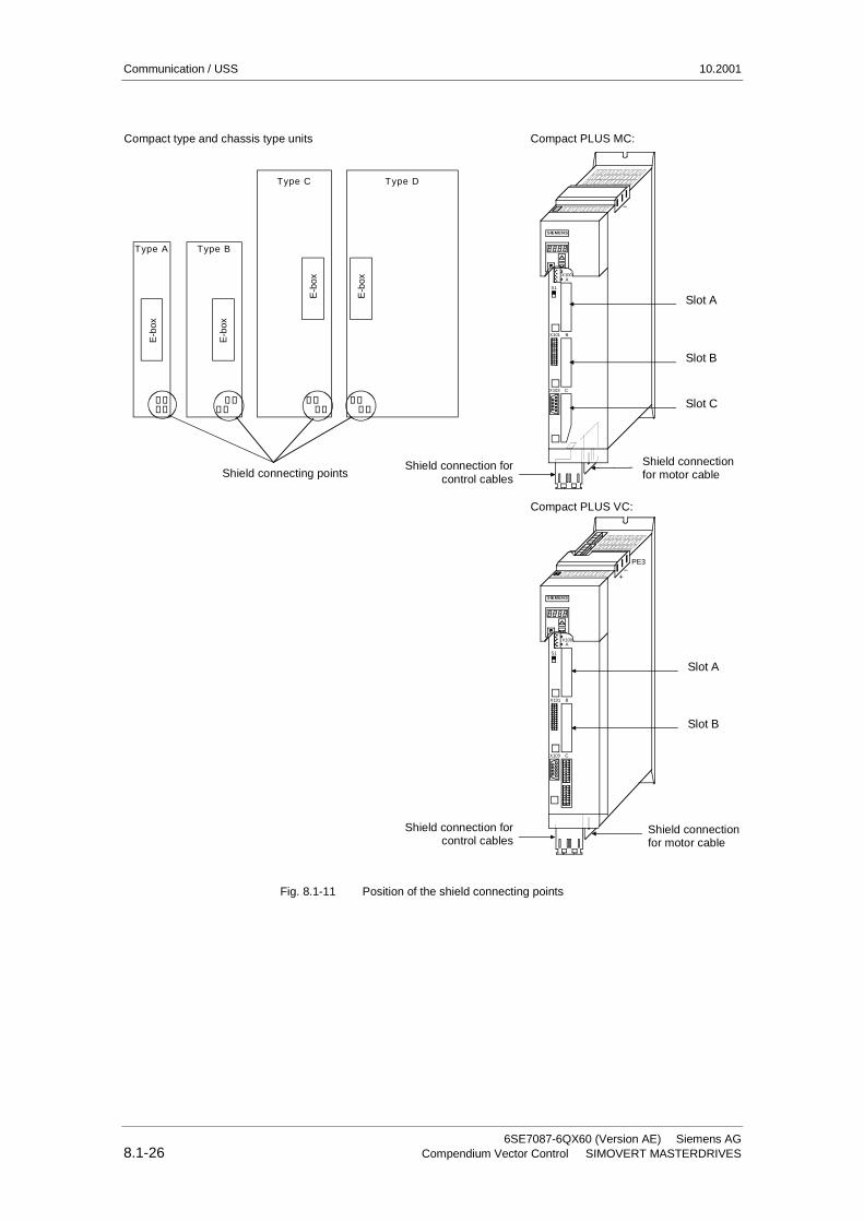
6SE7087-6QX60 (Version AE) Siemens AG8.1-26 Compendium Vector Control SIMOVERT MASTERDRIVES
Type A Type B
Type C Type D
E-b
ox
E-b
ox
E-b
ox
E-b
ox
SIEMENS
X100A
S1
BX101
CX103
Slot A
Slot B
Slot C
Shield connection forcontrol cables
Shield connectionfor motor cable
−
Compact type and chassis type units Compact PLUS MC:
Shield connecting points
Compact PLUS VC:
Slot A
Slot B
SIEMENS
X100A
S1
BX101
CX103
PE3−
+
Shield connectionfor motor cable
Shield connection forcontrol cables
Fig. 8.1-11 Position of the shield connecting points

10.2001 Communication / USS
Siemens AG 6SE7087-6QX60 (Version AE)SIMOVERT MASTERDRIVES Compendium Vector Control 8.1-27
Equipotential bonding is necessary in order to prevent differences inpotential (e.g. due to different supply voltages) between the individualbus nodes (converters and master system).
♦ This is achieved with the help of equipotential-bonding conductors:
• 16 mm2 Cu for equipotential-bonding conductors up to 200 m inlength
• 25 mm2 Cu for equipotential-bonding conductors more then200 m in length
♦ The equipotential-bonding conductors are to be laid so that there isthe smallest possible surface area between a conductor and anysignal cables.
♦ The equipotential-bonding conductor must be connected to the earthelectrode/protective conductor through the largest possible surfacearea.
Housing earthShield bar
External 0 Vsignal level
Bus terminationand
Basic network
Equipotential bonding
RS485 NSield
RS485 PData line
+ 5 V
390
220 220
+ 5 V
390 390
390
Fig. 8.1-12 Shielding and equipotential bonding
Instructions for laying cables:
♦ Bus cables (signal cables ) must not be laid close to and parallel topower cables.
♦ Signal cables and the associated equipotential-bonding cables mustbe laid as closely together as possible and kept as short aspossible.
♦ Power cables and signal cables must be laid in separate cableducts.
♦ Shields must be connected through the largest possible surfacearea.
For more information on electromagnetically compatible installation ofsystems, see for example Chapter 3 of the Compendium or thedescription "Instructions for Design of Drives in Conformance with EMCRegulations" (Order No. 6SE7087-6CX87-8CE0).
Equipotentialbonding
Laying cables

Communication / USS 10.2001
6SE7087-6QX60 (Version AE) Siemens AG8.1-28 Compendium Vector Control SIMOVERT MASTERDRIVES
8.1.4.4 Bus termination, USS protocol
In order to ensure interference-free USS operation, the bus cable mustbe terminated with bus terminating resistors at both ends. The buscable from the first USS node to the last USS node is to be regarded asone bus cable. The USS bus therefore must be terminated twice. Thebus terminating resistors must be switched in at the first bus node (e.g.master) and last bus node (e.g. converter).
SIEMENS
X100A
S1
BX101
CX103
Shield connectionfor control cables
Shield connectionfor motor cable
−
Compact PLUS
S1
ON
OFF
Switch forbus termination
Fig. 8.1-13 S1 bus-terminating switches in the Compact PLUS type of unit
In the Compact and chassis type units, two mutually independent USSinterfaces (SCom1 and SCom2) are available. Switch S1 or S2 isprovided for switching in the terminating resistor.
If the bus-terminating node is a T100 board, the bus terminatingresistors are switched in through the two plug-in jumpers, X8 and X9.
NOTE

10.2001 Communication / USS
Siemens AG 6SE7087-6QX60 (Version AE)SIMOVERT MASTERDRIVES Compendium Vector Control 8.1-29
♦ When the unit is supplied, the terminating resistors are notswitched in!
♦ Please note that the bus termination is switched in only at the firstbus node (e.g. SIMATIC S 5/CP524) and last bus node (e.g.CUMC)! When the matching resistors are being set, the electronicsbox must be isolated from supply!
♦ Data transmission faults possible on the bus!During active bus operation, the units with a switched-interminating resistor must not be disconnected from supply. Thematching resistor when disconnected from supply (off-load) is nolonger effective because the terminating resistor obtains its voltagefrom the connected unit.
The following illustration shows an example of the bus connection atterminal strip X100 (Compact PLUS). If the connector at terminal stripX100 of one node is removed, data transfer via bus is not interrupted.The other nodes on the bus continue to be supplied with data via thebus.
RS
485N
RS
485P
Higher-level computer (master)
with activated bus termination
S lave 1
X 1 0 036 35 34 33
S lave 2
X 1 0 036 35 34 33
S lave n
X 1 0 036 35 34 33
Last slave,bus termination
activatedS1
ON OFF
S1
ON OFF
S1
ON OFF
ConnectShield
Connect shield toconverter housing
Fig. 8.1-14 Connection of the 2-wire bus cable at terminal strip X100(Compact PLUS)
NOTE
Bus connection viaterminal strip

Communication / USS 10.2001
6SE7087-6QX60 (Version AE) Siemens AG8.1-30 Compendium Vector Control SIMOVERT MASTERDRIVES
The following illustration shows the structure of a bus connection viathe 9-pin connector, X103 (Compact PLUS).
RS
485
P
RS
485
N
No bus terminationSwitch S1 "OFF"
At the last node on the bus cable, switch S1 must be in the "ON" position.
RS485 N RS485 P RS485 N RS485 P
To the master 9-pole Sub-D 9-pole Sub-D
9-pole Sub-D 9-pole Sub-D
X103 X103
8 3 8 3
Fig. 8.1-15 Connection of the 2-wire bus cable at terminal strip X103(Compact PLUS)
Bus connection viaconnector X103

10.2001 Communication / USS
Siemens AG 6SE7087-6QX60 (Version AE)SIMOVERT MASTERDRIVES Compendium Vector Control 8.1-31
8.1.5 Start-up
The USS protocol can be started up in two steps:
1. Parameterization of the USS protocol at the "selected" interface
2. Parameterization of process-data interconnections and the"parameterizing enable" for the selected interface.
Parameterizing the USS protocol
Create the right conditions:
• Set P060 = 1 (menu selection)
Parameterize the interface:
Settings to be made:
• P682 (SCB protocol) only applies to the SCB2,
• P700 (SCom/SCB BusAddr), P701 (SCom/SCB baud rate),
• P702 (SCom/SCB PKW #), P703 (SCom/SCB PcD # and P704(SCom/SCB TlgOFF)
Parameterizing the parameterizing enable and process-datainterconnections
Set the parameterizing enable via USS at the selected interface:
• Set P053 (parameter access)
Set process-data interconnections:
• For status words and actual values:P707 (Src SCom 1 TrnsDat) and P708 (Src SCom 2 TrnsDat) for CUMCP690 (SCB actual value) for SCB 2 board
• For control words and setpoints:e.g. P554 (control word, bit 0) to P591 (control word, bit 32),P443 (Src Main Setp), P433 (Src Add Setp1), etc.
Communication / USS 10.2001
6SE7087-6QX60 (Version AE) Siemens AG8.1-32 Compendium Vector Control SIMOVERT MASTERDRIVES
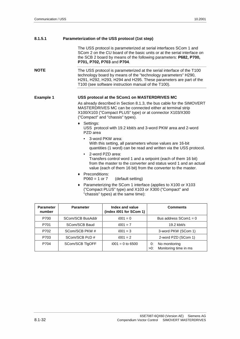
8.1.5.1 Parameterization of the USS protocol (1st step)
The USS protocol is parameterized at serial interfaces SCom 1 andSCom 2 on the CU board of the basic units or at the serial interface onthe SCB 2 board by means of the following parameters: P682, P700,P701, P702, P703 and P704.
The USS protocol is parameterized at the serial interface of the T100technology board by means of the "technology parameters" H290,H291, H292, H293, H294 and H295. These parameters are part of theT100 (see software instruction manual of the T100).
USS protocol at the SCom1 on MASTERDRIVES MCAs already described in Section 8.1.3, the bus cable for the SIMOVERTMASTERDRIVES MC can be connected either at terminal stripX100/X103 ("Compact PLUS" type) or at connector X103/X300("Compact" and "chassis" types).
♦ Settings:USS protocol with 19.2 kbit/s and 3-word PKW area and 2-wordPZD area
• 3-word PKW area:With this setting, all parameters whose values are 16-bitquantities (1 word) can be read and written via the USS protocol.
• 2-word PZD area:Transfers control word 1 and a setpoint (each of them 16 bit)from the master to the converter and status word 1 and an actualvalue (each of them 16 bit) from the converter to the master.
♦ Preconditions:P060 = 1 or 7 (default setting)
♦ Parameterizing the SCom 1 interface (applies to X100 or X103("Compact PLUS" type) and X103 or X300 ("Compact" and"chassis" types) at the same time):
Parameternumber
Parameter Index and value(index i001 for SCom 1)
Comments
P700 SCom/SCB BusAddr i001 = 0 Bus address SCom1 = 0
P701 SCom/SCB Baud i001 = 7 19.2 kbit/s
P702 SCom/SCB PKW # i001 = 3 3-word PKW (SCom 1)
P703 SCom/SCB PcD # i001 = 2 2-word PZD (SCom 1)
P704 SCom/SCB TlgOFF i001 = 0 to 6500 0: No monitoring>0: Monitoring time in ms
NOTE
Example 1

10.2001 Communication / USS
Siemens AG 6SE7087-6QX60 (Version AE)SIMOVERT MASTERDRIVES Compendium Vector Control 8.1-33
USS protocol at the SCom2 (only in Compact type and chassistype units)
♦ Setting:USS protocol with 38.4 kbit/s and 4-word PKW area and 6-wordPZD area
• 4-word PKW area:With this setting, all parameters whose values are 16-bit (= 1word) or 32-bit (double word) quantities can be read or written viathe USS protocol.
• 6-word PZD area:Transfers control words 1 and 2 and a maximum of four setpoints(each of them 16 bits) from the master to the converter or controlwords 1 and 2 (each one of them 16 bits) and a maximum of fouractual values (each one of them 16 bits) from the converter to themaster.
♦ Preconditions:P060 = 1 or 7
♦ Parameterizing the SCom2 interface (CUMC: X103, CUVC: X101):
Parameternumber
Parameter Index and value(index i002 for SCom 2)
Comments
P700 SCom/SCB BusAddr i002 = 15 Bus address, SCom 2 = 15
P701 SCom/SCB Baud i002 = 8 38.4 kbit/s
P702 SCom/SCB PKW # i002 = 4 4-word PKW (SCom 2)
P703 SCom/SCB PcD # i002 = 6 6-word PZD (SCom 2)
P704 SCom/SCB TlgOFF i002 = 0 to 6500 0: No monitoring>0: Monitoring time in ms
Example 2
Communication / USS 10.2001
6SE7087-6QX60 (Version AE) Siemens AG8.1-34 Compendium Vector Control SIMOVERT MASTERDRIVES
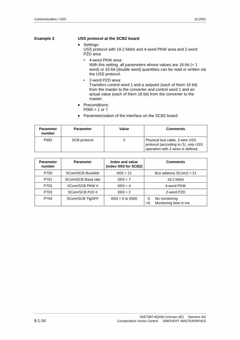
USS protocol at the SCB2 board
♦ Settings:USS protocol with 19.2 kbit/s and 4-word PKW area and 2-wordPZD area
• 4-word PKW area:With this setting, all parameters whose values are 16-bit (= 1word) or 32-bit (double word) quantities can be read or written viathe USS protocol.
• 2-word PZD area:Transfers control word 1 and a setpoint (each of them 16 bit)from the master to the converter and control word 1 and anactual value (each of them 16 bit) from the converter to themaster.
♦ Preconditions:P060 = 1 or 7
♦ Parameterization of the interface on the SCB2 board:
Parameternumber
Parameter Value Comments
P682 SCB protocol 2 Physical bus cable, 2-wire USSprotocol (according to /1/, only USSoperation with 2 wires is defined.
Parameternumber
Parameter Index and value(index i003 for SCB2)
Comments
P700 SCom/SCB BusAddr i003 = 21 Bus address SCom2 = 21
P701 SCom/SCB Baud rate i003 = 7 19.2 kbit/s
P702 SCom/SCB PKW # i003 = 4 4-word PKW
P703 SCom/SCB PcD # i003 = 2 2-word PZD
P704 SCom/SCB TlgOFF i003 = 0 to 6500 0: No monitoring>0: Monitoring time in ms
Example 3

10.2001 Communication / USS
Siemens AG 6SE7087-6QX60 (Version AE)SIMOVERT MASTERDRIVES Compendium Vector Control 8.1-35
USS protocol on the CBP2 board
♦ Settings:USS protocol with 19.2 kbit/s and 4-word PKW area and 2-wordPZD area
• 4-word PKW area:With this setting, all parameters whose values are 16 bit- (= 1word) or 32-bit variables (double word) can be read or written bymeans of the USS protocol.
• 2-word PZD area:Transmission of control word 1 and a setpoint (each 16 bits) fromthe master to the converter and of status word 1 and an actualvalue (each 16 bits) from the converter to the master.
♦ Requirements:P060 = 1 or 7
♦ Parameterization of the interface on the CBP2 board:
Parameternumber
Parameter Value Comments
P713.x CBP2 protocol 2 A change from PROFIBUS to USS protocoland vice versa only comes into effect whenthe voltage of the drive is turned off and thenon again.
Parameternumber
Parameter Value Comments
P918.x CBP2 BusAddr 21 Bus address CBP2 = 21
P718.x CBP2 Baud 7 19.2 kbit/s
P719.x CBP2 PKW #. 4 4-word PKW
P720.x CBP2 PcD #. 2 2-word PZD
P722.x CBP2 TlgOFF. 0...6500 0: No monitoring>0: Monitoring time in ms
Example 4

Communication / USS 10.2001
6SE7087-6QX60 (Version AE) Siemens AG8.1-36 Compendium Vector Control SIMOVERT MASTERDRIVES
8.1.5.2 Parameterizing the parameterizing enable and process-datainterconnections (2nd step)
During start-up, an interface with the USS protocol must be explicitlyenabled for parameterization in order to be able to change (= write) theparameters of a SIMOVERT MASTERDRIVES via this interface − thisapplies to the parameters of the basic unit (P/U parameters) and to thetechnology-board parameters (H/L parameters).
Access to the SIMOVERT MASTERDRIVES via USS protocol is onlypossible if, during start-up, the PKW area is appropriately defined tocontain 3, 4 words (fixed length) or a variable PKW length (= value 127)in the useful (net) data area.
The following rules apply to this:
♦ All parameters (P, r, U and n parameters of the basic units, or H, d,L and c parameters of the technology board) can be read out viaany interface. For reading purposes, it is not necessary that theinterface has been enabled for parameterization.
P, U, H and L parameters: Can be read and writtenr, n, d and c parameters: Can only be read
♦ Parameterizing enable is specified in parameter P053 (parameteraccess). This parameter can always be written from any interface.
♦ Several interfaces can be in possession of a parameterizing enablesimultaneously.
SCB2
T100
CUMC
Interfaces Value for P053
USS interface
USS interface
USS interface at SCom2(not in Compact PLUS)
USS interface at SCom1
PMU
8
16
32
4
2
H parametersd parameters
P parametersr parameters
Fig. 8.1-16 Parameterizing enable for the USS interfaces
Parameterization ofthe parameterizingenable
NOTE

10.2001 Communication / USS
Siemens AG 6SE7087-6QX60 (Version AE)SIMOVERT MASTERDRIVES Compendium Vector Control 8.1-37
The rules for generating the value which is entered in parameter P053for specifying parameter access is explained with the followingexample.
Setting the parameterizing enable for SIMOVERT MASTERDRIVESwith SCB2
Setting:Write access to the parameters of the basic units (P parameters) viathe PMU as well as via the USS protocol at both SCom1 interfaces andon SCB2
Parameter number Value Comments
P053 14 2 = PMU, 4 = SCom1, 8 = SCB2⇒ value = 2 + 4 + 8 = 14
As already described in Section 8.1.2.3 (PZD area), the PZD areaconsists of a maximum of 16 words. During start-up, the length of thisarea is defined in words using parameter P703 (SST/SCB PZD #). Thisdefinition applies to the telegram from the master to the converter and,vice versa, to the telegram from the converter back to the master. In thetelegram from the master to the converter, the PZD area containscontrol word 1 or control word 2 and the setpoints. In the telegram fromthe converter to the master, status word 1 or status word 2 and theactual values are transferred.
1 word 1 word 1 word 1 word
PZD1 PZD2 PZD3 • • • PZD16
Maximum 16 wordsMinimum 0 words, i.e. no PZD area in the net data block
Here, process-data interconnection is only described for the basic units.Process-data interconnection for the technology boards is described intheir instruction manual.
Example
Parameterizingprocess-datainterconnections
NOTE

Communication / USS 10.2001
6SE7087-6QX60 (Version AE) Siemens AG8.1-38 Compendium Vector Control SIMOVERT MASTERDRIVES
The two control words (bits 0 to 15) and 2 (bits 16 to 31) givecommands and external information to the converter. A selectparameter is assigned to each control-word bit, e.g. bit 0 of parameterP554. The select parameter specifies from which source(s) this controlbit can be influenced (= changed).
USS interface, from which controlword bits 0 to 15(= control word 1)
are to be changed (source)
Values to which select parametersP554 to P575 are to be set
SCom1 21xy
SCom2 61xy
SCB2 45xy
Note:
♦ e.g. 21xy:The first digit (here 2) identifies the interface SST1 as source.The second digit (here 1) indicates that it is the 1st word in the PZDarea of the telegram. "xy" (= 00 to 15) identifies the bit position.
Control word 1 is always transferred in the 1st word of the PZD area inthe USS protocol.
♦ The control word command "ON/OFF1" should be taken from bit 0 inthe 1st PZD word of SST1.
♦ The control word command "OFF2" should be taken from bit 1 in the1st PZD word of SST1.
♦ The control word command "ACK" should be taken from bit 7 in the1st PZD word of SST1.
Parameternumber
Parameter Index and value
(index i001 for BICO data set 1)(index i002 for BICO data set 2)
Comments
P554 Source ON/OFF1 i001 = 2001 ON/OFF from SCom1
P555 Source 1 OFF2 i001 = 2001 Operating condition/OFF2 from SCom1
P565 Source 1 ACK i001 = 2107 Edge 0 ⇒ 1
etc.
"Interconnecting"control word 1 andcontrol word 2
NOTE
Example 1

10.2001 Communication / USS
Siemens AG 6SE7087-6QX60 (Version AE)SIMOVERT MASTERDRIVES Compendium Vector Control 8.1-39
The following values of select parameters P576 to P591 are to be setfor the USS interfaces:
USS interface from which control-word bits 16 to31 (= control word 2) are to be changed (source)
Values to which select parameters P576 toP591 are to be set
SCom1 24xy
SCom2 (not with the Compact PLUS) 64xy
SCB2 48xy
Note:
♦ e.g. 48xy:The first position (in this case, 4) identifies the interface on SCB 2 asthe source.The second digit (here 8) indicates that it is the 4th word in the PZDarea of the telegram (5 signifies the 1st word). "xy" (= 00 to 15)identifies the bit position.
If necessary, control word 2 is always transferred in the 4th word of thePZD area in the USS protocol.⇒ Set PZD area to a length of at least 4 words (P703).
♦ Bit 0 for switching over the function data set should be taken frombit 0 in the 4th PZD word of SCB2.
♦ Bit1 for switching over the function data set should be taken frombit 1 in the 4th PZD word of SCB2.
Parameternumber
Parameter Index and value
(index i001 for BICO data set 1)(index i002 for BICO data set 2)
P576 Source FDS Bit 0 i001 = 4800
P577 Source FDS Bit 1 i001 = 4801
etc.
Values of selectparameters P576 toP591
NOTE
Example 2

Communication / USS 10.2001
6SE7087-6QX60 (Version AE) Siemens AG8.1-40 Compendium Vector Control SIMOVERT MASTERDRIVES
The user can select the source from which the setpoints for theconverter are to be taken. This is done in the same way in whichcontrol-word bits are "interconnected". This is now illustrated with twoexamples.
The "wiring" of the setpoints is done via parameters P443 (source mainsetpoint) and P433 (source supplementary setpoint 1).
Source for setpoints Value for parameters P443 and P428
Interface allocation:SCom1SCB2
20xx45xx
Position of the setpoints (16 bitquantify) in the PZD area:In the 2nd word ⇒ 02In the 3rd word ⇒ 03etc.
xx = 02, 03, 04 (only if control word 2 isnot transferred), 05, up to 16
The main setpoint comes from SCom 1 and is located in the 2nd wordof the PZD area. The supplementary setpoint comes from the USSinterface on SCB 2 and is also located in the 2nd word of the PZD area(for BICO data set 1).
Parameternumber
Parameter Index and value
(index i001 for BICO data set 1)(index i002 for BICO data set 2)
P443 Source of main setpoint i001 = 2002
P433 Source of supplementarysetpoint 1
i001 = 4502
"Interconnection" ofsetpoints
Example 1

10.2001 Communication / USS
Siemens AG 6SE7087-6QX60 (Version AE)SIMOVERT MASTERDRIVES Compendium Vector Control 8.1-41
The "wiring" of the setpoints is done via parameters P443 (source mainsetpoint), P433 (source supplementary setpoint 1), P438 (sourcesupplementary setpoint 2), and so on. For a detailed description, seethe instruction manual.
Source for the setpoints Values for parameters P443, P433, P438 andso on
Interface allocation:SCom1SCom2SCB2
20xx60xx45xx
Position of the setpoints (16-bit quantity) in the PZDarea:In the 2nd word ⇒ 02In the 3rd word ⇒ 03 and so on
xx = 02,03, 04 (only if control word 2 is nottransferred), 05, up to 16
Position of the setpoints (32-bit quantity) in the PZDarea:In the 2nd word + 3rd word ⇒ 32
Rules for generating:xx = 30 (indicates 32-bits) + position in the PZD area atwhich the 32-bit setpoint begins.In the 3rd word and 4th word ⇒ 33 and so on
x x = 32,33 (only if control word 2 is nottransferred), 34 (only if control word 2 is nottransferred), 35, up to 45
When 32-bit quantities are being transferred, the high word is located inPZD n and the low word in PZD n+1⇒ For example, 32-bit setpoint in PZD2 and PZD3; the high-word isthen transferred in PZD2 and the low word in PZD3 via the USS bus.
The main setpoint (32-bit quantity) comes from SCom1 and is locatedin the 2nd word and 3rd word of the PZD area. Control word 2 is in the4th word. In the 5th and 6th words, supplementary setpoint 1 (32-bitquantity) is transmitted (for BICO data set 1).
Parameternumber
Parameter Index and value
(index i001 for BICO data set 1)(index i002 for BICO data set 2)
P443 Source of main setpoint i001 = 2032
P433 Source of supplementarysetpoint 1
i001 = 2035
Example 2
NOTE

Communication / USS 10.2001
6SE7087-6QX60 (Version AE) Siemens AG8.1-42 Compendium Vector Control SIMOVERT MASTERDRIVES
The two status words 1 (bits 0 to 15) and 2 (bits 16 to 31) sendmessages from the converter to a higher-level converter system.
An indexed parameter is assigned to each interface. Each index isassigned to a net-data word in the PZD area. For example, index i001to the 1st word, index i002 to the 2nd word and so on up to i016.
Parameternumber
Parameter Index and value
(index i001 for BICO data set 1)(index i002 for BICO data set 2)
SCom1 707 (SCom1 actualvalues)
i001 to 016
SCom2(not with the
Compact PLUS)
708 (SCom2 actualvalues)
i001 to 016
SCB2 706 (SCB actual values) i001 to 016
Status word 1 is always transferred in the 1st word of the PZD area inthe USS protocol.
"Interconnection" of status word 1 and the actual speed/frequency(KK0091) at interface SCom1.
♦ Precondition:PZD area at least 2 words in length; P703, i001 ≥ 2 is set.
ParameterNo.
Parameter Index and value Comments
P707 SCom1 actualvalues
i001 = 0032 1st word in the PZD area:status word (K0032)
i002 = 0091 2nd word in the PZD area:actual speed/frequency (KK0091, only H-Word)
i003 to i016 = 0 3rd to 16th word in the PZD area (if parameterized):"Not interconnected"
"Interconnection" ofstatus words 1 and 2and the actualvalues
NOTE
Example 1

10.2001 Communication / USS
Siemens AG 6SE7087-6QX60 (Version AE)SIMOVERT MASTERDRIVES Compendium Vector Control 8.1-43
"Interconnection" of status word 1, status word 2, actual speed(KK0091) and the actual DC link voltage (K0240) at the interface onSCB2.
♦ Precondition:PZD area at least 5 words in length; P703, i003 ≥ 5 is set.
Parameternumber
Parameter Index and value Comments
P706 SCB actualvalues
i001 = 0032 1st word in the PZD area:status word (K0032)
i002 = 0091 2nd word in the PZD area:high word of the actual speed (KK0091)
i003 = 0091 3rd word in the PZD area:low word of the actual speed (KK0091)
i004 = 0033 4th word in the PZD area:status word 2 (K0033)
i005 = 0240 5th word in the PZD area:Vd(act) (K0240)
When 32-bit quantities are being transferred, the high word is located inPZD n, the low word in PZD n+1.⇒ For example, 32-bit actual value of KK0091 in PZD2 and PZD3.
Example 2
NOTE