7 inspection of completed structural members - in.gov · 7 inspection of completed structural...
TRANSCRIPT

7 Inspection of Completed
Structural Members
Checking Dimensions
Checking Camber
Checking Plumb
Defects Minor Defects
Inspection and Repair of Surfaces
Cracks
Major Defects
Rejection of Structural Member
7-1
CHAPTER SEVEN:
INSPECTION OF COMPLETED STRUCTURAL
MEMBERS
CHECKING DIMENSIONS
After the side forms are stripped and the surfaces of the structural member have been examined for defective concrete, the Technician is required to check the completed structural member. The dimensions, including camber, horizontal alignment (sweep), and plumb are checked against the requirements on the approved shop drawings and/or INDOT standards to determine if the structural member is within the allowable tolerances. The tolerances are shown on INDOT Standard Drawings 707- BPBF-01 to BPBF-04.
Structural members with dimensions falling outside the specified tolerances are required to be rejected unless approved measures to correct the deficiency are completed. The QCP is required to contain provisions for corrective measures for an out of tolerance structural member. A written corrective action plan shall be presented to the Engineer for approval. Length measurements that are slightly outside the tolerance limit, especially in the case of structural members of considerable length, are subject to review. The temperature of the concrete at the time the measurements are made will have some influence on the length; however, the influence of the temperature on other measurements may be considered negligible. Grinding of beams to allow measurements to fall within the specified tolerance may be permitted only with the written approval of the Engineer. The limits of tolerance do not necessarily represent acceptable fabrication but are the limits at which fabrication may become unacceptable. The Fabricator is required to work at a level of quality that is well within the tolerance limits. The Technician is required to inform the Fabricator of dimensions that approach the tolerance limits so that the proper adjustments may be made in future fabrication of members.
CHECKING CAMBER
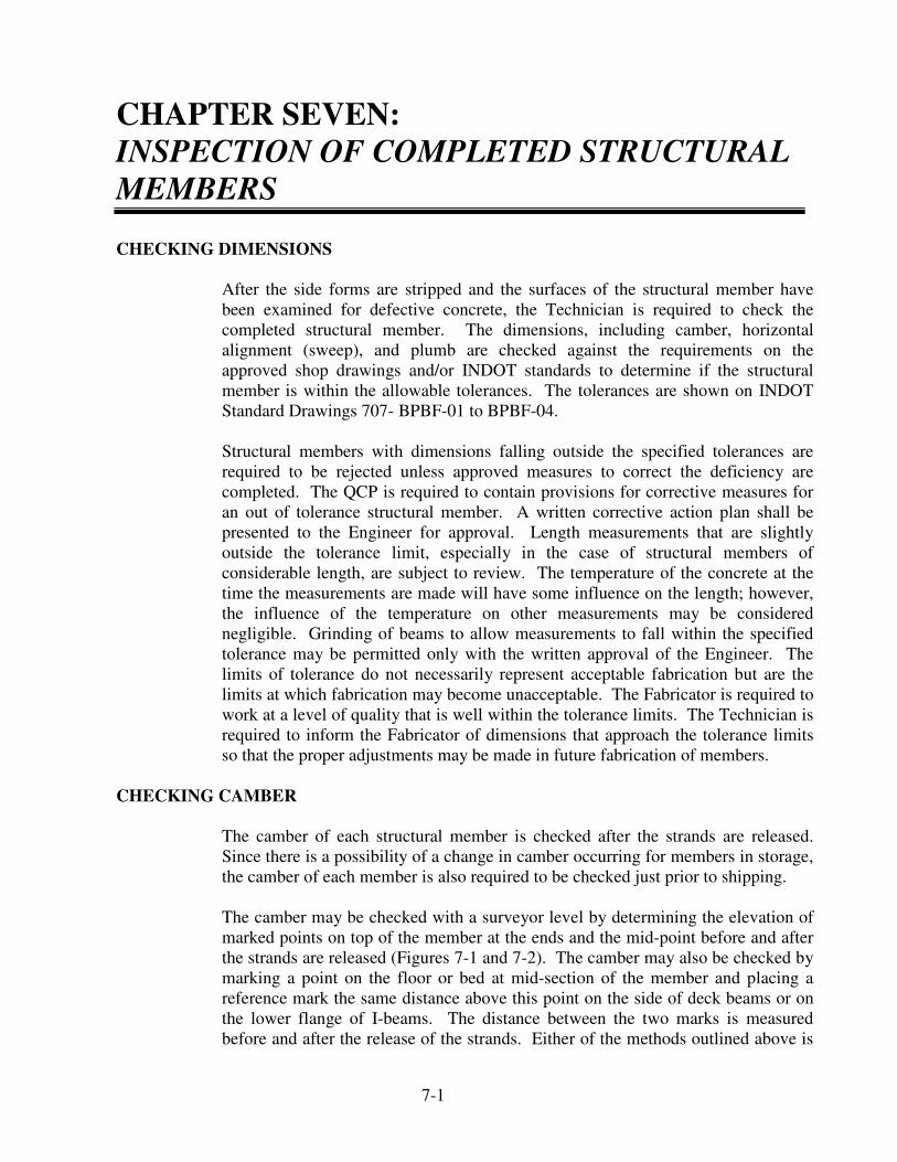
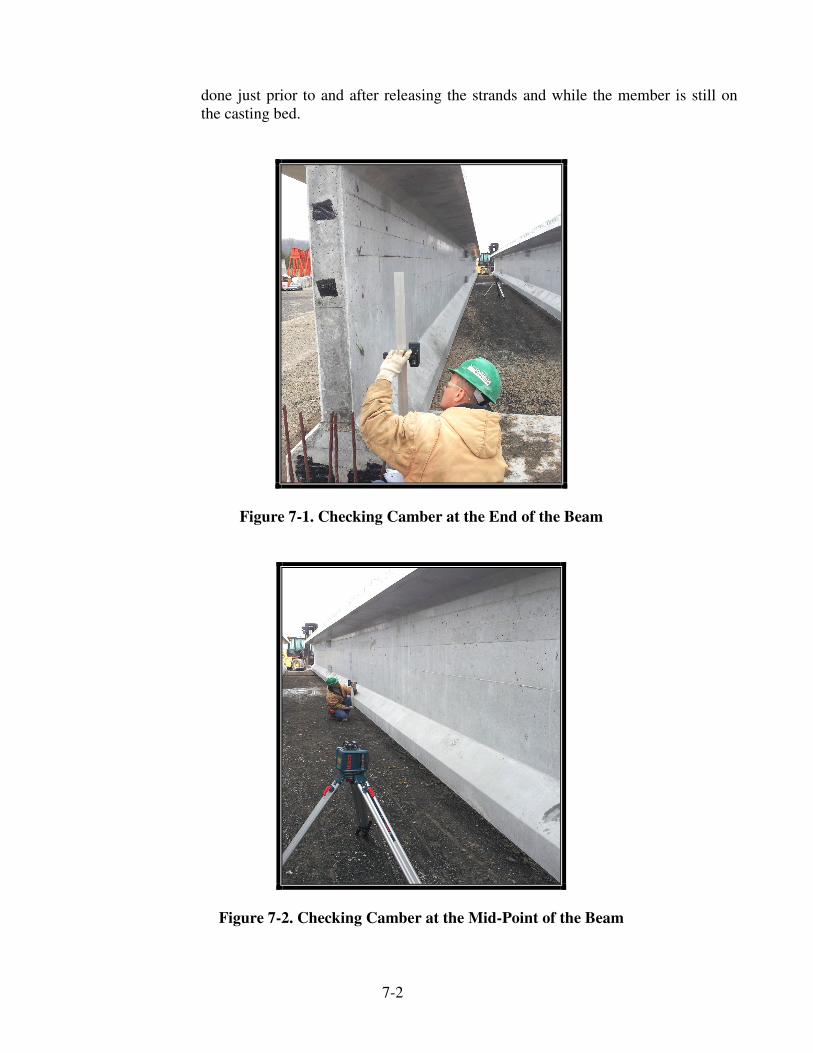
The camber of each structural member is checked after the strands are released. Since there is a possibility of a change in camber occurring for members in storage, the camber of each member is also required to be checked just prior to shipping.
The camber may be checked with a surveyor level by determining the elevation of marked points on top of the member at the ends and the mid-point before and after the strands are released (Figures 7-1 and 7-2). The camber may also be checked by marking a point on the floor or bed at mid-section of the member and placing a reference mark the same distance above this point on the side of deck beams or on the lower flange of I-beams. The distance between the two marks is measured before and after the release of the strands. Either of the methods outlined above is
7-2
done just prior to and after releasing the strands and while the member is still on the casting bed.
Figure 7-1. Checking Camber at the End of the Beam
Figure 7-2. Checking Camber at the Mid-Point of the Beam
7-3
Another method of checking the camber that may be done at any time the member is accessible is by means of a wire or line. The procedure is as follows:
1) Place a straight edge transversely under the beam at the ends and
mid-point
2) Measure the same distance at the three points vertically above the straight edge and place a mark on the side or flange of the member
3) Stretch a wire or line tightly between the marks at the ends of the
member and record the distance between the wire or line and the mark at the mid-point of the member
Care is taken to assure that there is a minimum amount of sag in the wire or line. Any sag not compensated for is included as camber in the member. Tests may be conducted in advance to determine the maximum length for which this compensation would be sufficiently accurate. The pull or tension necessary for various lengths of wire or line to reduce the sag to a minimum may be determined and the sag measured at mid-point with a surveyor level or other suitable means. When checking for camber, the pull or tension for a certain length wire or line is used and the sag deducted from the mid-point measurement. The remaining measurement is the amount of camber in the beam. The variation of camber is required to be more than that allowed in the plans or standard drawings 707-BPBF-01 thru 04. If the camber is outside the allowable tolerances or is already at the erection camber at the time of release, the DTE, PE, and Contractor are immediately notified.
The shipping camber is recorded on Form IT 573 (Yellow Card) and IC 735 (Appendix A).
CHECKING PLUMB
The plumb or vertical alignment of the beams is checked after the strands are released. Since there is a possibility of a change in plumb occurring while a member is in storage, the Technician is required to check the plumb of each member just prior to shipping. The Technician should note that many beams have top and bottom flanges of different widths. Checking plumb is generally done by placing a carpenter level against the end of the beam and observing the vertical centerline of the beam section in relation to true vertical.
DEFECTS
The Technician will contact the DTE for determination of the final disposition of the structural member when a minor or major defect in the structural member is observed. All communications between the Fabricator, Prime Contractor, PE/S, DTE, and Technician may be done by means of written or electronic notification. Acceptance or rejection of the structural member will be done by the DTE. The
7-4
District Field Engineer in the Division of Construction Management or the Office of Materials Management may be contacted if there are any questions concerning the quality of the structural member.
MINOR DEFECTS
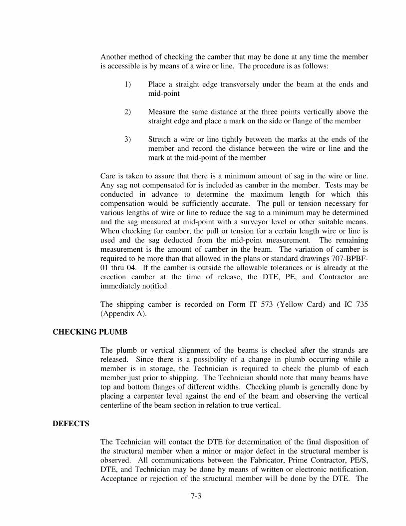
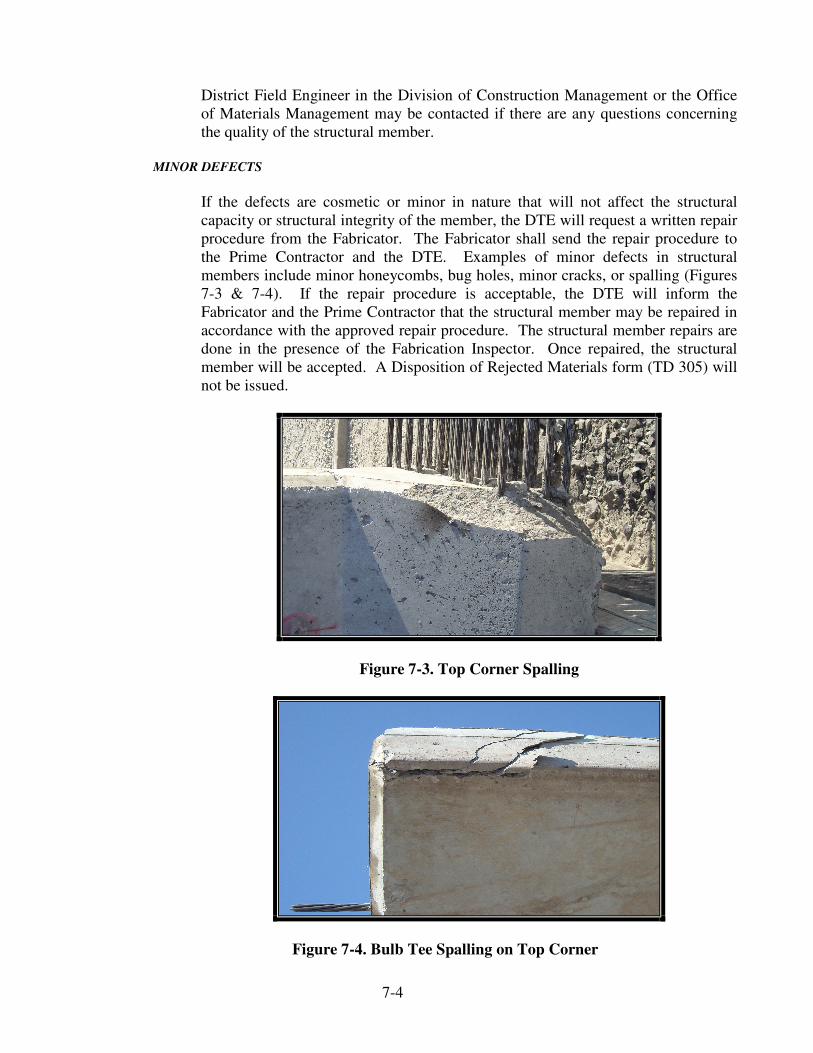
If the defects are cosmetic or minor in nature that will not affect the structural capacity or structural integrity of the member, the DTE will request a written repair procedure from the Fabricator. The Fabricator shall send the repair procedure to the Prime Contractor and the DTE. Examples of minor defects in structural members include minor honeycombs, bug holes, minor cracks, or spalling (Figures 7-3 & 7-4). If the repair procedure is acceptable, the DTE will inform the Fabricator and the Prime Contractor that the structural member may be repaired in accordance with the approved repair procedure. The structural member repairs are done in the presence of the Fabrication Inspector. Once repaired, the structural member will be accepted. A Disposition of Rejected Materials form (TD 305) will not be issued.
Figure 7-3. Top Corner Spalling
Figure 7-4. Bulb Tee Spalling on Top Corner
7-5
INSPECTION AND REPAIR OF SURFACES
Immediately after the removal of the forms, the concrete surfaces are inspected for honeycomb, voids, or other defects. Members having honeycombs or voids in or near the bottom of a member bearing area, or surrounding or exposing strands of reinforcing bars or prestressing strands, are generally rejected. Minor honeycombs or voids not affecting the strength of a structural member may be repaired when approved by the DTE. The method of repair is required to be submitted in writing. After the defective concrete has been removed, the area is examined by the DTE. Repairs are required to be made in the presence of the Technician.
All repairs are required to be rubbed even with adjoining surfaces. Any evidence of plastering over an area or repairing a defective area without approval of the DTE is sufficient cause for rejection of the member. The depressions left in the bottom of pre-tensioned members with draped strands after removal of the hold-down bolts are required to be cleaned of oil or grease and the surface roughened or keyed. The bottom and sides of the depression are completely coated with an approved bonding compound, and the depression filled with a preapproved patch. Unless these precautions are taken, the grout will most likely fall out due to the flexure of the structural member.
CRACKS
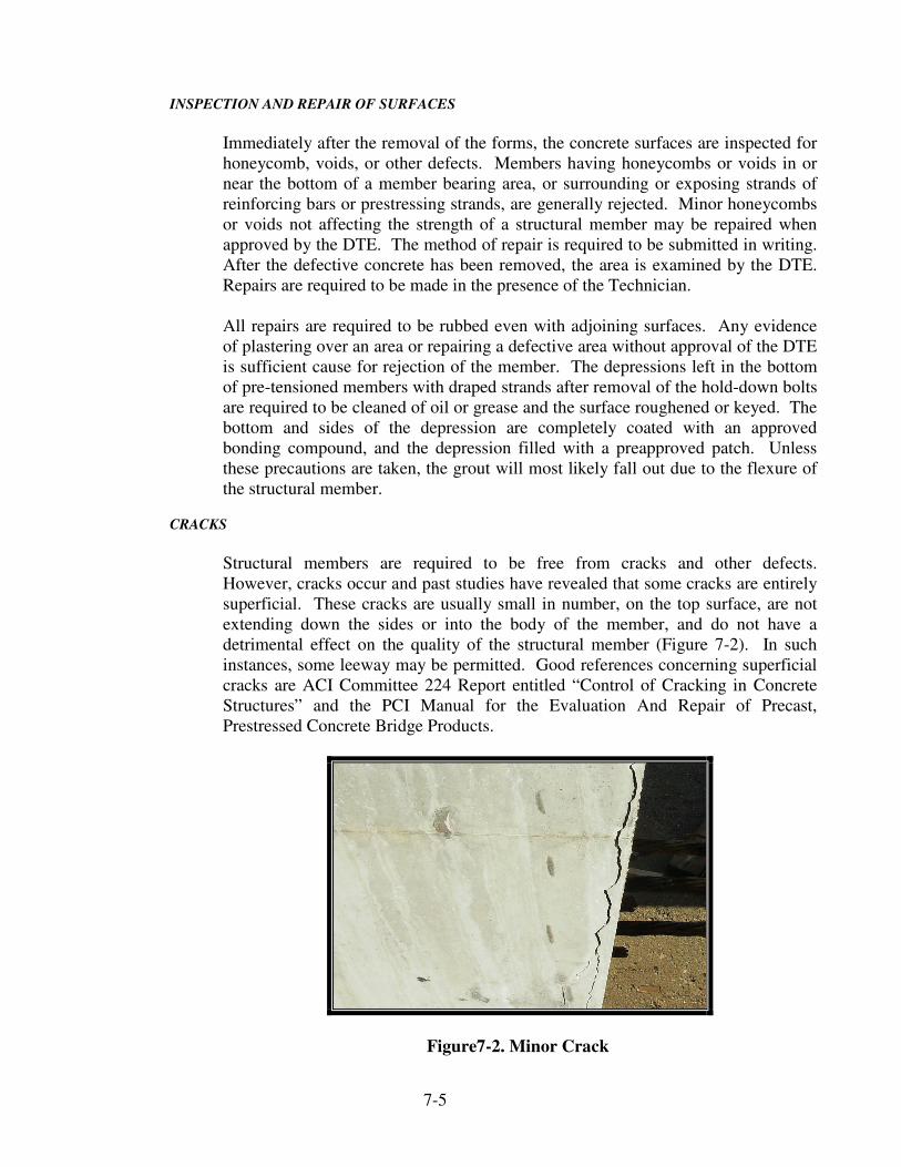
Structural members are required to be free from cracks and other defects. However, cracks occur and past studies have revealed that some cracks are entirely superficial. These cracks are usually small in number, on the top surface, are not extending down the sides or into the body of the member, and do not have a detrimental effect on the quality of the structural member (Figure 7-2). In such instances, some leeway may be permitted. Good references concerning superficial cracks are ACI Committee 224 Report entitled “Control of Cracking in Concrete Structures” and the PCI Manual for the Evaluation And Repair of Precast, Prestressed Concrete Bridge Products.
Figure7-2. Minor Crack
7-6
Cracks constitute potential locations for the start of disintegration of the concrete and no members with cracks, however small, are accepted unless the cracks are effectively sealed against the entrance of water with a suitable epoxy resin.
Cracks on the top surface of members are required to be grooved to a depth of 1/4 in. to hold the sealing material. Cracks on the sides of members, which are only hair-line width, may be painted with the sealing material. End cracks are required to be sealed before the ends are given the required coatings of asphalt paint.
Each instance of crack occurrence is considered individually. When there is a possibility that a member with cracks may be acceptable, the extent and magnitude of the crack or cracks is determined before the decision for acceptance may be made. The method used to determine the extent and magnitude of the cracks is required to not reduce the structural capacity of the member. Whenever the Technician has any doubt about the acceptability of a member, the DTE is contacted.
MAJOR DEFECTS
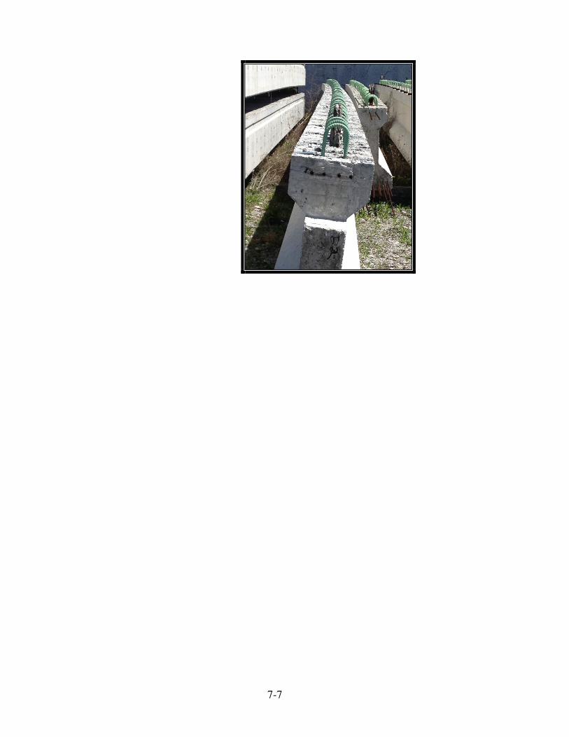
If the DTE believes the defects could affect the structural capacity or structural integrity of the member, the DTE will issue a TD 305 and send copies to the Prime Contractor, Fabricator, and PE/S. Examples of major defects in structural members include stirrups not extending high enough above the top of the beam, fewer than the required number of strands extending from the end of the beam, or wrong reinforcing bars used in the beam.
The Prime Contractor is responsible for consulting with the Fabricator concerning the acceptance or rejection of the structural member. The procedures shall be as follows:
1) If the Prime Contractor elects not to have INDOT pursue an investigation,
the DTE will notify the Fabricator that the structural member is unacceptable and a new structural member will be required.
2) If the Prime Contractor elects to have INDOT pursue an investigation of the
structural member, a written repair procedure is required by the Fabricator. Copies of the repair procedure are sent by the Fabricator to the Prime Contractor, PE/S, and the DTE.
3) The DTE will forward the repair procedure to the Designer of Record for an
investigation.
4) The Designer of Record will review the repair procedure and make a recommendation to the DTE for acceptance of the repair procedure to the structural member or rejection of the structural member. The expenses incurred by the Designer of Record to evaluate the structural member will be submitted to the DTE.
7-7
5) If the Designer of Record does not accept the recommendation for repair of the structural member, the DTE will document on the TD 305 that the structural member is unacceptable and a new structural member will be required.
6) If the Designer of Record accepts the recommendation for repair of the
structural member, the DTE will document the required repairs on the TD 305.
7) The DTE will issue the final recommendation and may either concur with
the Designer of Record recommendation or provide another recommendation. The DTE will complete the TD 305 with the appropriate recommendation and send a copy to the Prime Contractor, Fabricator, PE/S, INDOT Inspector and the Office of Materials Manageent of the final decision regarding the acceptance or rejection of the structural member.
8) The costs for the evaluation of the structural member will be assessed to the
Prime Contractor by means of the TD 305. These costs will include the DTE expenses for the time and travel to inspect the structural member, the Designer of Record expenses to evaluate the structural member, the Fabricator Inspector expenses for the time to monitor the repair, and any other incurred expenses. An additional penalty may be assessed for structural members that do not meet the specification requirements and have defects that are determined to not affect the structural capacity or structural integrity of the member. A minimum of $1000.00 or the actual cost of the investigation if more than $1000.00 will be assessed.
9) The Prime Contractor may appeal the decision of the DTE by sending a
notification to appeal to the DTE within 15 days from the date of the notification of the failure. The basis of appeal in detail is required to be included in the notification. The DTE will review the appeal and send the decision to the Prime Contractor.
REJECTION OF STRUCTURAL MEMBER
If the defects are significant, the quality of the structural member does not meet specification requirements, and the DTE decides that the structural member cannot be modified to meet the specification requirements, the DTE may reject the structural member by sending a notification to the Fabricator. A TD 305 will not be issued. The Fabricator may appeal the failed materials decision by sending a notification to appeal to the DTE within 15 days from the date of the notification of the failure. The basis of appeal in detail is required to be included in the notification. The DTE will review the appeal and send the decision to the Fabricator.
7-7