7 chapter 7: serviceability...
TRANSCRIPT

1
7 CHAPTER 7: SERVICEABILITY REQUIREMENTS
7.1 Introduction
A properly designed reinforced concrete element is to satisfy two requirements; strength and serviceability. Strength requirements are elaborately dealt with in previous chapters.
Serviceability refers to some requirements that are needed to make the structure serviceable such as no excessive deflection or cracking. These are discussed in this chapter.
Historically, deflections and crack widths have not been a problem for reinforced concrete elements. With the introduction of strength design and high strength steel reinforcement, the reinforcement stresses at service loads have increased considerably. Since crack widths and deflections are related to steel stresses, each of these has become more critical.
7.2 Deflection
Excessive deflections can impair the appearance and efficiency of a structure and cause discomfort or alarm to the occupants. Excessive deflections can cause cracking and possible separation of plaster finishes, and crushing of partition walls.
The ACI Code provisions for control of deflections are concerned only with deflections that occur at service load levels under static conditions and may not apply to loads with strong dynamic characteristics such as those due to earthquakes, transient winds, and vibrating machinery.
Deflection of a reinforced concrete element is made up of two components; short-term deflection and long-term deflection. These will be dealt within the next sections.
7.2.1 Deflection Control
Two methods are given in the ACI Code for controlling deflections for beams and one-way slabs not supporting or attached to partitions or other construction likely to be damaged by large deflections. The first method indirectly controls deflection by means of minimum thickness, as shown in Table 7.1, and the second by directly limiting computed deflections, as shown in Table 7.2.

2
Table 7.1: Minimum Thickness of Beams and One-way Slabs
Restraint simply supported
one end continuous
both ends continuous cantilever
Member Members not supporting or attached to partitions or other construction likely to be damaged by large deflections
Solid one-way slabs 20
l 24
l 28l
10l
Beams or ribbed one-way slabs
16l
5.18l
21l
8l
* The values given above are only valid for 2/4200 cmkgfy = . For
reinforcement having yf other than 2/4200 cmkg , the values listed in the
table are to be multiplied by
+
700040.0 yf
** l = span length measured center-to-center
Table 7.2: Maximum Permissible Computed Deflections
Type of member Deflection to be considered Deflection limitation
Flat roofs not supporting or attached to non-structural elements likely to be damaged by large deflections
Immediate deflection due to live load L
180/l
Floors not supporting or attached to non-structural elements likely to be damaged by large deflections
Immediate deflection due to live load L
360/l
Roof or floor construction supporting or attached to non-structural elements likely to be damaged by large deflections
480/l
Roof or floor construction supporting or attached to non-structural elements not likely to be damaged by large deflections
That part of the total deflection occurring after attachment of nonstructural elements (sum of the long-term deflection due to all sustained loads and the immediate deflection due to any additional live load)
240/l
3
7.2.2 Short-term Deflection
Short-term deflections of beams and one-way slabs occur immediately on the application of load to a structural member. The principal factors that affect the short-term deflection of a member are:
a. Magnitude and distribution of loads.
b. Span and restraint conditions.
c. Cross-sectional dimensions and amount of reinforcement.
d. Material properties.
e. Extent of flexural cracking.
Figure 7.1 shows short term deflection for several cases of loading and support conditions.

4
Figure 7.1: Short-term deflections for several cases of loading and support conditions
7.2.2.1 Effective Moment of Inertia
The flexural rigidity of a beam may not be constant along its length because of varying amount of steel reinforcement and cracking at different sections along the beam.
According to ACI Code 9.5.2.2 and 9.5.2.3, short-term deflection is computed using elastic methods of analysis considering effects of cracking and reinforcement on member stiffness,
eci IE
wL384
5 4
max =∆ec
i IEwL
384
4
max =∆
cci IE
wL8
4
max =∆
eci IE
wL185
4
max =∆
eci IE
PL48
3
max =∆ eci IE
PL3
3
max =∆
)43(24
22max aL
IEPa
eci −=∆
LIEbPa
eci 3
22
max =∆
)3(6
2
max bLIE
Pb
eci −=∆
eci IE
ML16
2
max =∆

5
with the modulus of elasticity for concrete cc fE ′=15100 and with the effective moment
of inertia eI given as follows, but not greater than gI .
cra
crg
a
cre I
MMI
MMI
−+
=
33
1 ( 7.1 )
31 ≤≤cr
a
MMwhere
and the cracking moment crM is given in Eq. (7.2)
t
grcr y
IfM = ( 7.2)
aM = maximum moment in member at stage deflection is computed
gI = moment of inertia of gross concrete section about centroidal axis, neglecting
reinforcement
crI = moment of inertia of cracked section transformed to concrete
rf = modulus of rupture of concrete = cf ′2
ty = distance from centroidal axis of gross section, neglecting reinforcement, to extreme
fiber in tension.
The effective moment of inertia provides a transition between the upper and lower limits of
gI and crI as a function of the level of cracking represented by cra MM / . When cra MM /
is less than or equal to 1, eI is taken equal to gI . When cra MM / is larger than or equal to
3, eI is taken equal to crI , as shown in Figure 7.2.
Figure 7.2: variation in effective moment of inertia with moment

6
For each load combination being considered, such as dead load or dead plus live load, deflections should be calculated using an effective moment of inertia eI computed with
corresponding service load moment, aM . The incremental deflection caused by the
addition of load, such as live load, is then computed as the difference between deflection computed for any two-load combinations.
According to ACI Code 9.5.2.4, effective moment of inertia for continuous members is permitted to be taken as the average values obtained from Eq. (7.1) for the critical positive and negative moment sections. Furthermore, for prismatic members, effective moment of inertia is permitted to be taken as the value obtained from Eq. (7.1) at midspan for simple and continuous spans, and at support for cantilevers.
7.2.2.2 Transformed Concrete Section
(a) Rectangular sections with tension reinforcement only:
The moment of inertia of a cracked beam ( crI ) with tension reinforcement, shown in Figure
7.3, is computed as follows:
Figure 7.3: Cracked transformed section of singly reinforced beam
Taking moment of areas about the neutral axis
( )dkdAndk
dkb s −=
2
where c
s
EE
n = = modular ratio of elasticity, but not less than 6.0,
kd = distance from the neutral axis to the extreme compression fiber.
Letting sAn
bB =

7
BdB
dk112 −+
= ( 7.3)
Moment of inertia of gross concrete section is given by
12/3hbI g = ( 7.4)
Moment of inertia of cracked section about neutral axis,
( )233 3/ kddAndkbI scr −+= ( 7.5)
(b) Rectangular sections with tension and compression reinforcement:
For the rectangular section shown in Figure 7.4,
Figure 7.4: Cracked transformed section of doubly reinforced beam
Letting ( )
s
s
AnAn
r′−
=1
( ) ( ) ( ) BrrddrdBkd /11/12 2
+−++′+= ( 7.6)
12/3hbI g = ( 7.4)
( ) ( ) ( )2233 13/ dkdAnkddAndkbI sscr ′−′−+−+= ( 7.7)
(c) T- sections with tension reinforcement only:
From Figure 7.5,

8
Figure 7.5: Cracked transformed section of singly reinforced T-beam
1. When fhdk ≤ , the section is treated as a singly reinforced rectangular section with wb
replaced with b .
2. When fhkd > relevant equations are given below
Letting s
w
Anb
C = , and ( )
s
wf
Anbbh
f−
=
( )[ ]( ) hbhbb
hbhbbhy
wfw
wfwt +−
+−−=
222/1 ( 7.8)
( ) ( ) ( ) CfffhdCkd f /112 2
+−+++= ( 7.9)
( )( ) ( ) ( )22
33
2/2/
12/12/
hyhbyhhhbb
hbhbbI
twtffw
wfwg
−+−−−+
+−= ( 7.10)
( )( )( ) ( )22
333
2/
3/12/
kddAnhkdbbh
dkbhbbI
sfwf
wfwcr
−+−−+
+−= ( 7.11)
(d) T- sections with tension and compression reinforcement:
As shown in Figure 7.6,
9
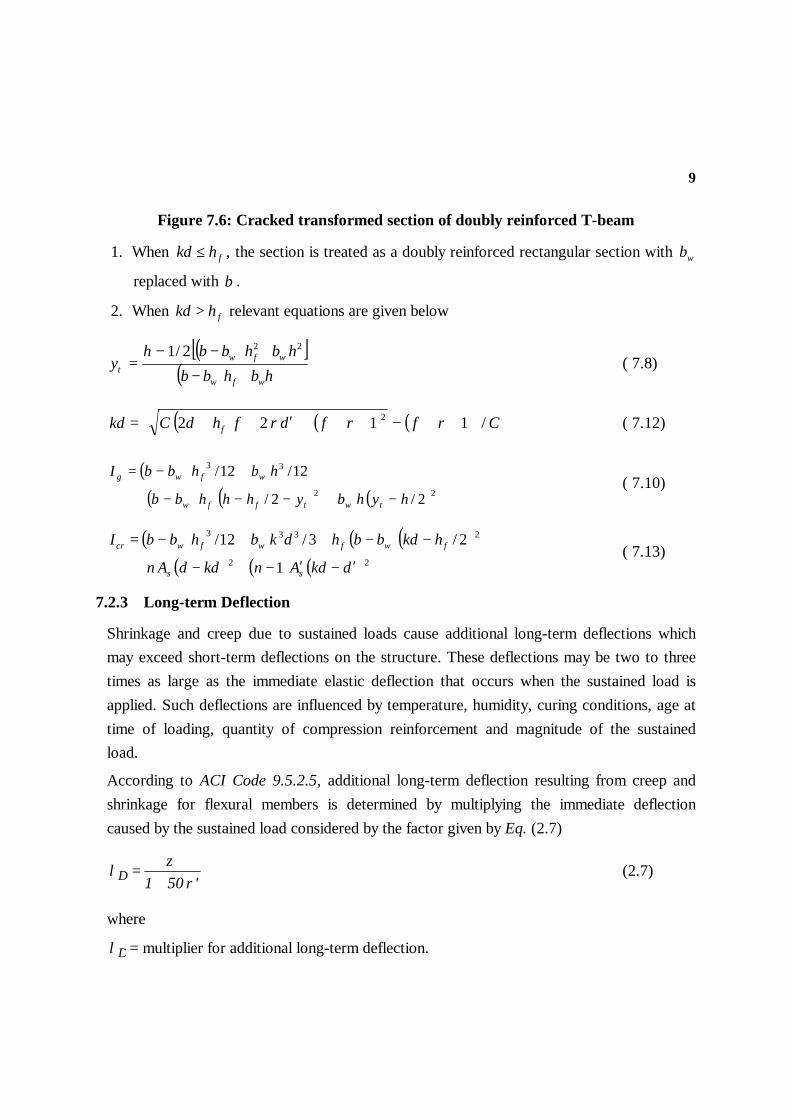
Figure 7.6: Cracked transformed section of doubly reinforced T-beam
1. When fhkd ≤ , the section is treated as a doubly reinforced rectangular section with wb
replaced with b .
2. When fhkd > relevant equations are given below
( )[ ]( ) hbhbb
hbhbbhy
wfw
wfwt +−
+−−=
222/1 ( 7.8)
( ) ( ) ( ) CrfrfdrfhdCkd f /1122 2
++−+++′++= ( 7.12)
( )( ) ( ) ( )22
33
2/2/
12/12/
hyhbyhhhbb
hbhbbI
twtffw
wfwg
−+−−−+
+−= ( 7.10)
( ) ( )( )( ) ( ) ( ) 22
2333
1
2/3/12/
dkdAnkddAn
hkdbbhdkbhbbI
ss
fwfwfwcr
′−′−+−+
−−++−= ( 7.13)
7.2.3 Long-term Deflection
Shrinkage and creep due to sustained loads cause additional long-term deflections which may exceed short-term deflections on the structure. These deflections may be two to three times as large as the immediate elastic deflection that occurs when the sustained load is applied. Such deflections are influenced by temperature, humidity, curing conditions, age at time of loading, quantity of compression reinforcement and magnitude of the sustained load.
According to ACI Code 9.5.2.5, additional long-term deflection resulting from creep and shrinkage for flexural members is determined by multiplying the immediate deflection caused by the sustained load considered by the factor given by Eq. (2.7)
'501 ρζ
λ∆ += (2.7)
where
∆λ = multiplier for additional long-term deflection.

10
dbAs′=′ρ is the compression reinforcement ratio taken at midspan for simple and
continuous spans and at support for cantilevers.
sA′ = cross sectional area of compression reinforcement
b = width of cross section
d = effective depth of cross section
ξ = time-dependent factor for a sustained load, given in Table 7.3.
Table 7.3: Time-dependent factors
Period (months) ξ
3 1.0 6 1.2
12 1.4 60 2.0
Multipliers for long-term deflection are also given in Figure 2.8.
Example (7.1): For the simply supported beam shown in Figure 7.7, calculate the maximum short-term deflection and maximum deflection at an age of 5 years. It is given that service dead load on beam, including own weight, = mton /1 , concentrated service live load = tons3 , 100
% of which is sustained. Use 2/300 cmkgfc =′ and 2/4200 cmkgf y = .
Figure 7.7: Loaded beam and its cross section
Solution: Moments:
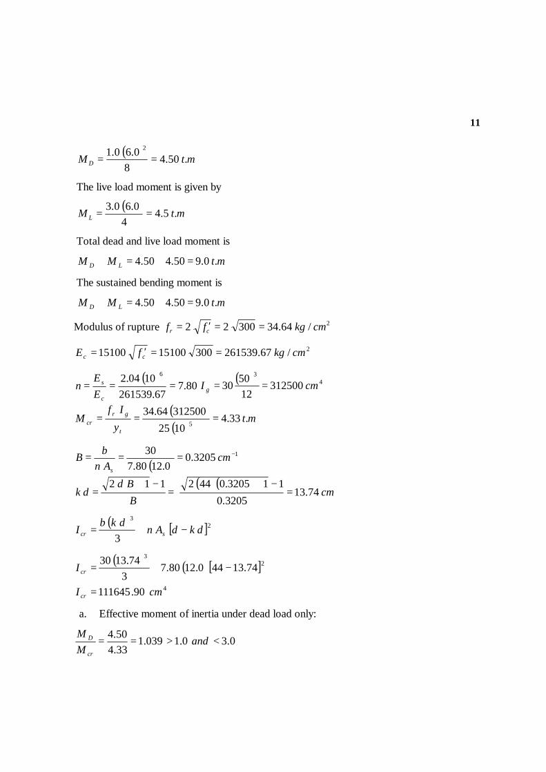
The dead load moment is given as
11
( ) mtMD .50.48
0.60.1 2
==
The live load moment is given by
( ) mtML .5.44
0.60.3==
Total dead and live load moment is
mtMM LD .0.950.450.4 =+=+
The sustained bending moment is
mtMM LD .0.950.450.4 =+=+
Modulus of rupture 2/64.3430022 cmkgff cr ==′=
2/67.2615393001510015100 cmkgfE cc ==′=
( )80.7
67.2615391004.2 6
===c
s
EE
n( ) 4
3
312500125030 cmI g ==
( )( )
mty
IfM
t
grcr .33.4
102531250064.34
5 ===
( )13205.0
0.1280.730 −=== cm
AnbB
s
( ) ( )cm
BBd
dk 74.133205.0
113205.0442112=
−+=
−+=
( ) [ ]23
3dkdAn
dkbI scr −+=
( ) ( ) [ ]4
23
90.111645
74.13440.1280.73
74.1330
cmI
I
cr
cr
=
−+=
a. Effective moment of inertia under dead load only:
0.30.1039.133.450.4
<>== andMM
cr
D
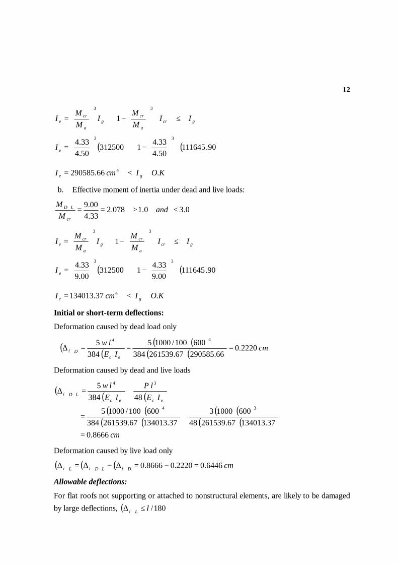
12
gcra
crg
a
cre II
MM
IMM
I ≤
−+
=
33
1
( ) ( )90.11164550.433.41312500
50.433.4 33
−+
=eI
KOIcmI ge .66.290585 4 <=
b. Effective moment of inertia under dead and live loads:
0.30.1078.233.400.9
<>==+ andM
M
cr
LD
gcra
crg
a
cre II
MM
IMM
I ≤
−+
=
33
1
( ) ( )90.11164500.933.41312500
00.933.4 33
−+
=eI
KOIcmI ge .37.134013 4 <=
Initial or short-term deflections:
Deformation caused by dead load only
( ) ( )( ) ( )
( ) ( ) cmIE
lw
ecDi 2220.0
66.29058567.261539384600100/10005
3845 44
===∆
Deformation caused by dead and live loads
( ) ( ) ( )( ) ( )
( ) ( )( ) ( )
( ) ( )cm
IElP
IElw
ececLDi
8666.037.13401367.26153948
6001000337.13401367.261539384
600100/10005
483845
34
34
=
+=
+=∆ +
Deformation caused by live load only
( ) ( ) ( ) cmDiLDiLi 6446.02220.08666.0 =−=∆−∆=∆ +
Allowable deflections:
For flat roofs not supporting or attached to nonstructural elements, are likely to be damaged by large deflections, ( ) 180/lLi ≤∆

13
KOcmcml .6446.0333.3180/600180/ >==
For floors, not supporting or attached to nonstructural elements, are likely to be damaged by large deflections, ( ) 360/lLi ≤∆
KOcmcml .6446.0667.1360/600360/ >==
Long-term deflection:
00.0=′ρ
Duration ξ '501 ρ
ζλ∆ +
= ( )susi∆ ( )Li∆ ( )susi∆λ∆
( )totali∆
5 years 2.0 2.0 0.8666 0.6446 1.7332 2.3778 For roof or floor construction supporting or attached to nonstructural elements is likely to be damaged by large deflections, ( ) ( ) 480/lLisusi ≤+ ∆∆λ∆
( ) ( ) cm3778.2Lisusi =+ ∆∆λ∆
cmcml 3778.225.1480/600480/ <==
i.e. thickness of beam needs to be increased.
For roof or floor construction, is supporting or attached to nonstructural elements, not likely to be damaged by large deflections, ( ) ( ) 240/llisusi ≤∆+∆λ
( ) ( ) cm3778.2lisusi =+ ∆∆λ∆
KOcmcml .3778.250.2240/600240/ >==
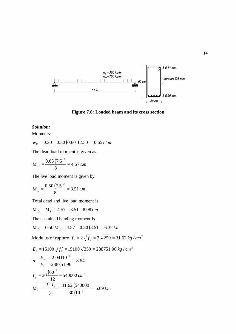
Example (7.2): For the simply supported beam shown in Figure 7.8, calculate the maximum short-term deflection and maximum deflections at ages of 3 months and 5 years. It is given that service dead load on beam, not including own weight, = mkg /200 , service live load = mkg /500 ,
50 % of which is sustained. Use 2/250 cmkgfc =′ and 2/4200 cmkgf y = .
14
Figure 7.8: Loaded beam and its cross section
Solution: Moments:
( ) ( ) mtwD /65.050.260.030.020.0 =+=
The dead load moment is given as
( )mtM D .57.4
85.765.0 2
==
The live load moment is given by
( )mtM L .51.3
85.750.0 2
==
Total dead and live load moment is
mtMM LD .08.851.357.4 =+=+
The sustained bending moment is
( ) mtMM LD .32.651.350.057.450.0 =+=+
Modulus of rupture 2/62.3125022 cmkgff cr ==′=
2/96.2387512501510015100 cmkgfE cc ==′=
( )54.8
96.2387511004.2 6
===c
s
EE
n
( ) 43
540000126030 cmI g ==
( )( )
mty
IfM
t
grcr .69.5
103054000062.31
5 ===
15
( )12237.0
7.1554.830 −=== cm
AnbB
s
( ) ( ) ( )( ) 26.0
7.1554.862.4154.81
=−
=′−
=s
s
AnAn
r
cmd 20.540.180.0460 =−−−=
cmd 50.570.080.00.4 =++=′
( ) ( ) ( ) BrrddrBddk /11/12 2
+−++′+=
( ) ( ) ( ) ( )( ) ( )( )
cmdk
dk
37.17]26.01
26.012.54/5.526.012237.02.542[)2237.0/1( 2
=+−
+++=
( ) [ ] ( ) [ ]223
13
ddkAndkdAndkb
I sscr ′−′−+−+=
( ) ( )[ ] ( ) ( )[ ] 223
5.537.1762.454.737.172.547.1554.83
37.1730−+−+=crI
429.239186 cmI cr =
a. Effective moment of inertia under dead load only:
0.1803.069.557.4
<==cr
D
MM
i.e. 4540000 cmII ge ==
b. Effective moment of inertia under sustained load:
0.30.111.169.532.6
<>== andMM
cr
sus
gcra
crg
a
cre II
MM
IMM
I ≤
−+
=
33
1
( ) ( )29.23918632.669.51540000
32.669.5 33
−+
=eI
KOIcmI ge .88.458710 4 <=
c. Effective moment of inertia under dead and live load:
0.30.142.169.508.8
<>==+ andM
M
cr
LD
16
gcra
crg
a
cre II
MM
IMM
I ≤
−+
=
33
1
( ) ( )29.23918608.869.51540000
08.869.5 33
−+
=eI
KOIcmI ge .33.344237 4 <=
Initial or short-term deflections:
Deformation caused by dead load only
( ) ( )( ) ( ) ( )
( ) ( ) cmIE
lw
ecDi 2077.0
54000096.23875138475065.0100/10005
3845 44
===∆
Deformation caused by sustained load
( ) ( )( ) ( ) ( )( ) ( ) cm
IElw
ecsusi 3385.0
88.45871096.23875138475090.0100/10005
3845 44
===∆
Deformation caused by dead and live loads
( ) ( )( ) ( ) ( )( ) ( ) cm
IElw
ecLDi 5765.0
33.34423796.23875138475015.1100/10005
3845 44
===∆ +
Deformation caused by live load only
( ) ( ) ( ) cmDiLDiLi 3688.02077.05765.0 =−=∆−∆=∆ +
Allowable deflections:
For flat roofs, not supporting or attached to nonstructural elements, are likely to be damaged by large deflections, ( ) 180/lLi ≤∆
KOcmcml .3688.0167.4180/750180/ >==
For floors, not supporting or attached to nonstructural elements, are likely to be damaged by large deflections, ( ) 360/lli ≤∆
KOcmcml .3688.0083.2360/750360/ >==
Long-term deflection:
( ) 00284.02.5430
62.4==′ρ

17
Duration ξ '501 ρ
ζλ∆ +
= ( )susi∆
( )Li∆ ( )susi∆λ∆
( )totali∆
3 months 1.0 0.875 0.3385 0.3688 0.296 0.665 5 years 2.0 1.751 0.3385 0.3688 0.593 0.962
For roof or floor construction, supporting or attached to nonstructural elements, is likely to be damaged by large deflections, ( ) ( ) 480/lLisusi ≤+ ∆∆λ∆
( ) ( ) cm962.0Lisusi =+ ∆∆λ∆
KOcmcml .962.0562.1480/750480/ >==
For roof or floor construction, supporting or attached to nonstructural elements, is not likely to be damaged by large deflections, ( ) ( ) 240/lLisusi ≤+ ∆∆λ∆
( ) ( ) cm962.0Lisusi =+ ∆∆λ∆
KOcmcml .962.0125.3240/750240/ >==
7.3 Crack width control
With the advent of high-strength steels and with the use of Strength Design Methods which allow higher stresses in reinforcement, control of flexural cracking has assumed more importance.
Crack widths are of concern for three main reasons: appearance, leakage, and corrosion. Wide cracks are unsightly and sometimes lead to concern by owners and occupants. Crack control is important in the design of liquid-retaining structures. Leakage is a function of crack width. Corrosion of reinforcement has traditionally been related to crack width. Modern studies suggest that the factors governing the eventual development of corrosion are independent of the crack width.
A simple and more practical equation has been adopted starting with the 1995 code which directly limits the maximum reinforcement spacing. The new method is intended to control surface cracks to a width that is generally acceptable in practice but may vary widely in a given structure. The new method, for this reason, does not support to predict crack widths in the field. According to the new method given in ACI Code 10.6.4, the spacing of reinforcement closest to tension surface shall not exceed that given by
18
cs
C5.2f
106400S −= ( 7.14 )
and maximum spacing of reinforcement is given as
smax f
84000S = ( 7.15)
where S = center-to-center spacing of flexural tension reinforcement nearest to the extreme tension face, and sf = calculated stress in reinforcement at service load computed as the
unfactored moment divided by the product of steel area and internal moment arm. It is permitted to take sf as 2/3 yf . cC = Clear cover from the nearest surface in tension to the
surface of flexural tension reinforcement.
7.4 Skin Reinforcement in Deep Flexural Members
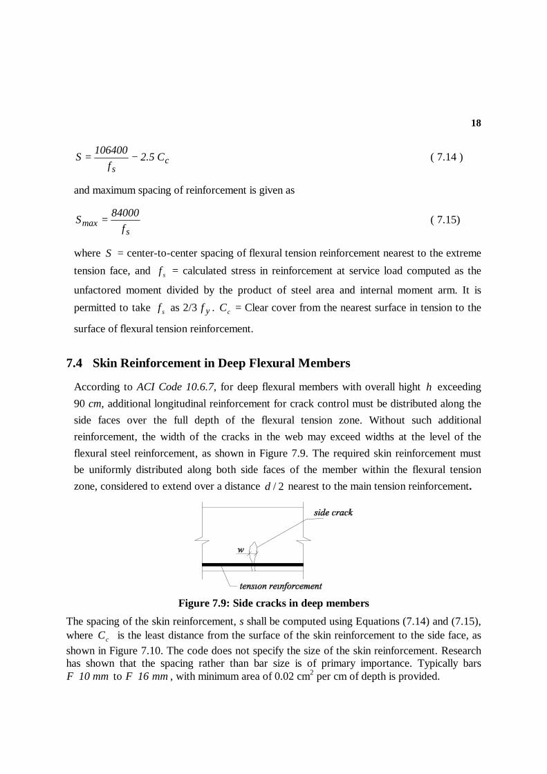
According to ACI Code 10.6.7, for deep flexural members with overall hight h exceeding 90 cm, additional longitudinal reinforcement for crack control must be distributed along the side faces over the full depth of the flexural tension zone. Without such additional reinforcement, the width of the cracks in the web may exceed widths at the level of the flexural steel reinforcement, as shown in Figure 7.9. The required skin reinforcement must be uniformly distributed along both side faces of the member within the flexural tension zone, considered to extend over a distance 2/d nearest to the main tension reinforcement.
Figure 7.9: Side cracks in deep members
The spacing of the skin reinforcement, s shall be computed using Equations (7.14) and (7.15), where cC is the least distance from the surface of the skin reinforcement to the side face, as shown in Figure 7.10. The code does not specify the size of the skin reinforcement. Research has shown that the spacing rather than bar size is of primary importance. Typically bars
mm10Φ to mm16Φ , with minimum area of 0.02 cm2 per cm of depth is provided.

19
Figure 7.10: Skin reinforcement
Example (7.3): For the cross section shown in Figure 7.11, determine whether the reinforcement satisfies ACI Code requirements for crack control.
Use 2/280 cmkgfc =′ and 2/4200 cmkgf y = .
Figure 7.11
Solution:
cs
C5.2f
106400S −=
cm8.480.00.4Cc =+=
( ) ( )8.45.242003/2
106400S −=
cm26S =

20
( ) K.Ocm0.26cm0.3042003/2
84000f
84000
s>==
Actual bar spacing (center-to-center) =
( ) ( ) K.Ocm0.26cm13.63
0.280.020.4230<=
−−−
7.5 Problems
P7.6.1 For the beam in Figure P7.6.1, (a) compute the short-term deflection produced by the total load, and (b) estimate the additional long-term deflection if the live load acts continuously, (c) if the beam supports nonstructural elements not likely to be damaged by large deflections, does the beam satisfy ACI Code requirements for allowable deflections?
Use 2/250 cmkgfc =′ and 2/4200 cmkgf y = .
Figure P7.6.1
P7.6.2 A simply supported beam with the cross section shown in Figure P7.6.2 has a span of 6.0 m and supports a service dead load of 2 t/m, including its own weight, in addition to a
service live load of 2.5 t/m. Use 2/300 cmkgfc =′ and 2/4200 cmkgf y = . Evaluate the
following:
1. The immediate deflection due to dead load only.
2. The immediate deflection due to dead and live loads.
3. The deflection at three month period assuming that 40 % of the live load is sustained.
21
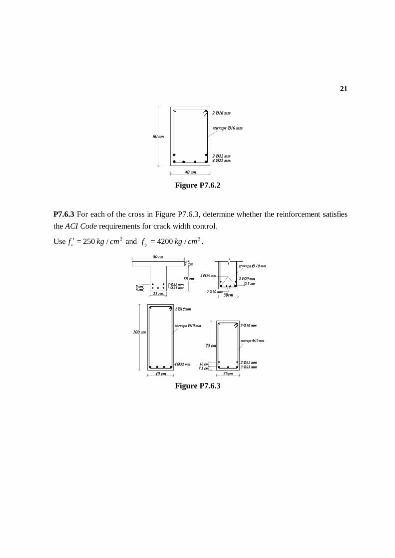
Figure P7.6.2
P7.6.3 For each of the cross in Figure P7.6.3, determine whether the reinforcement satisfies the ACI Code requirements for crack width control.
Use 2/250 cmkgfc =′ and 2/4200 cmkgf y = .
Figure P7.6.3