678 & 679 sure temp technical manual - frank's hospital ... · pdf filesuretemp®...
TRANSCRIPT
SureTemp ®
Model 678 & Model 679 Thermometer
Technical Manual

© 1997 by Welch Allyn, Inc. All rights reserved. No part of this manual may bereproduced or transmitted in any form or by any means, electronic ormechanical, including photocopy, without prior consent in writing from WelchAllyn. Printed in the U.S.A.
Welch Allyn and SureTemp are trademarks of Welch Allyn, Inc. All rightsreserved.
SureTemp® Model 678/SureTemp® Model 679 i
TABLE OF CONTENTS
TABLE OF CONTENTS............................................................................................................. i
LIST OF FIGURES ................................................................................................................... iii
WARRANTY .............................................................................................................................iv
SPECIFICATIONS.....................................................................................................................v
TERMINOLOGY .......................................................................................................................vi
1. OPERATIONAL CHARACTERISTICS ............................................................................... 1-1
Basic System Description .................................................................................................. 1-1Self Tests .......................................................................................................................... 1-3
Instrument Reset/Self Tests ....................................................................................... 1-3
Display Test ............................................................................................................... 1-3
Probe Warmer Circuit Self Tests................................................................................ 1-4
Battery Life ........................................................................................................................ 1-4Normal Mode..................................................................................................................... 1-5Monitor Mode .................................................................................................................... 1-6Pulse Timer Mode (Model 678 only) .................................................................................. 1-6
Backlight (Model 678 only) ......................................................................................... 1-6
F/C Conversion .......................................................................................................... 1-7
Temperature Recall.................................................................................................... 1-7
Biotech Mode .................................................................................................................... 1-7
2. PREVENTIVE MAINTENANCE ......................................................................................... 2-1
Cleaning and Sterilization .................................................................................................. 2-1Routine Cleaning........................................................................................................ 2-1
ETO Gas Sterilization Procedure................................................................................ 2-1
Battery Removal and Replacement ................................................................................... 2-2
3. CALIBRATION TESTING .................................................................................................. 3-1
Calibration Key Procedure................................................................................................. 3-1Model 9600 Calibration Testing Procedure........................................................................ 3-1

ii Welch-Allyn, Inc.
4. THEORY OF OPERATION................................................................................................ 4-1
Technical Overview ........................................................................................................... 4-1Probe Enhancements................................................................................................. 4-2
Probe Switch ..................................................................................................................... 4-2Normal Mode..................................................................................................................... 4-2Power Supply .................................................................................................................... 4-3
Low Battery Detection ................................................................................................ 4-3
Microcontroller............................................................................................................ 4-3
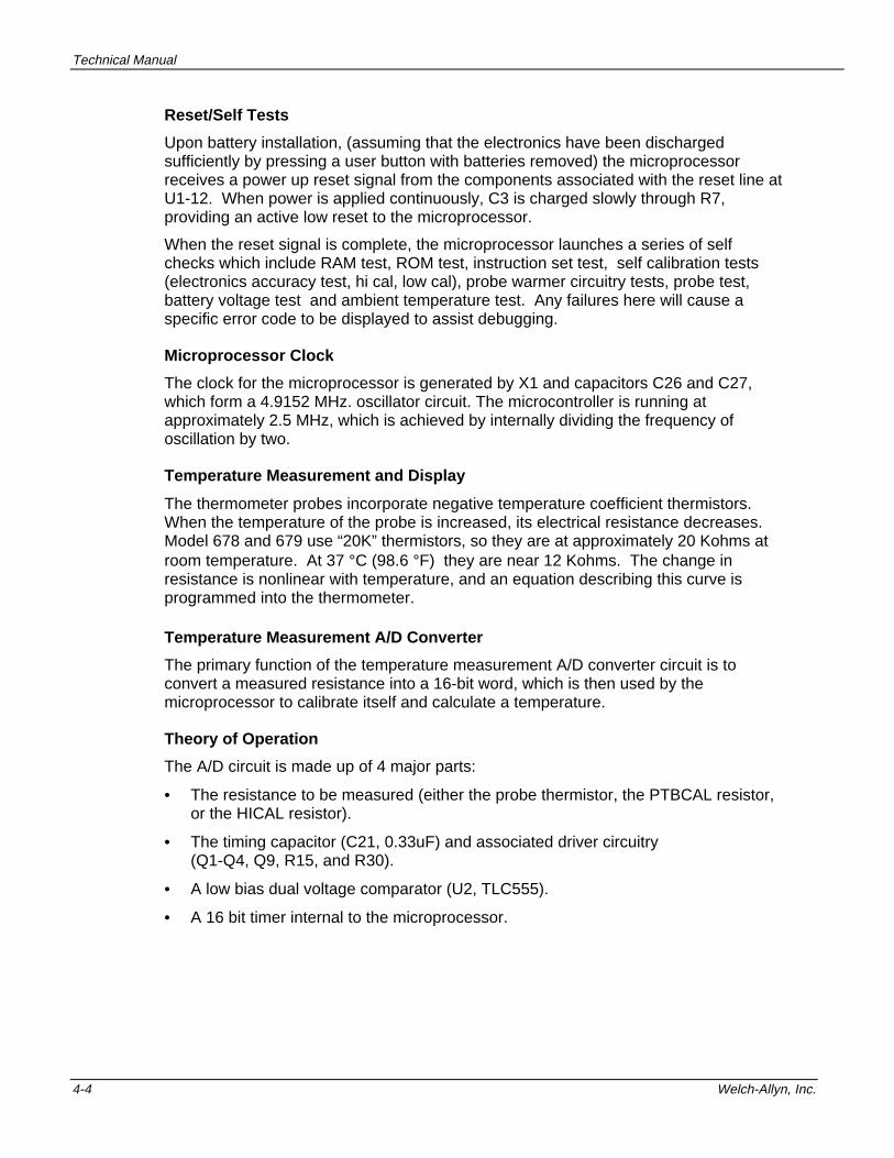
Reset/Self Tests......................................................................................................... 4-4
Microprocessor Clock................................................................................................. 4-4
Temperature Measurement and Display..................................................................... 4-4
Temperature Measurement A/D Converter................................................................. 4-4
Theory of Operation ................................................................................................... 4-4
Circuit Description ...................................................................................................... 4-5
Probe Identification Logic .................................................................................................. 4-6Basic Function............................................................................................................ 4-6
Circuit Operation ........................................................................................................ 4-7
Probe Warming ( Oral probes only) ................................................................................... 4-7Theory of Operation ................................................................................................... 4-7
Circuit Operation ........................................................................................................ 4-8
Other Components ............................................................................................................ 4-8Liquid Crystal Display ................................................................................................. 4-8
LCD Backlight (Model 678 Only) ................................................................................ 4-8
Probe Switch .............................................................................................................. 4-9
Mode Button............................................................................................................... 4-9
Timer Button (678 Only) ............................................................................................. 4-9
Serial Communications Port ....................................................................................... 4-9
Horn ........................................................................................................................... 4-9
5. TROUBLESHOOTING....................................................................................................... 5-1
Error Codes....................................................................................................................... 5-1Equipment Required.......................................................................................................... 5-2Troubleshooting Table....................................................................................................... 5-3Field Serviceable Repairs.................................................................................................. 5-8Field Serviceable Parts...................................................................................................... 5-8Model 678/679 Replacement Parts.................................................................................... 5-9Replacement Parts-Circuit Board Assemblies ................................................................. 5-10Thermometer Disassembly.............................................................................................. 5-12

SureTemp® Model 678/SureTemp® Model 679 iii
LIST OF FIGURES
FIGURE 1 - THERMOMETER DIAGRAM.............................................................................. 1-1
FIGURE 2 - M678 DISPLAY .................................................................................................. 1-3
FIGURE 3 - SYSTEM BLOCK DIAGRAM .............................................................................. 4-1
FIGURE 4 - PROBE LOGIC CIRCUITRY .............................................................................. 4-6
FIGURE 5 - PROBE LOGIC DIAGRAM ................................................................................. 4-6
FIGURE 6 - SELF-TEST /ERROR TABLE............................................................................. 5-2
FIGURE 7 - THERMOMETER ASSEMBLY DRAWING ....................................................... 5-13
FIGURE 8 - MAIN PCA........................................................................................................ 5-14
FIGURE 9 - ELECTRONICS ASSEMBLY............................................................................ 5-15
FIGURE 10 - SCHEMATICS................................................................................................ 5-17

iv Welch-Allyn, Inc.
WARRANTY
3-YEAR LIMITED WARRANTY ON NEW M678 AND ON M679 ONE PER ROOMINSTRUMENTS. 1-YEAR LIMITED WARRANTY ON NEW M679 INSTRUMENT :
Instrumentation purchased new from Welch Allyn, Inc. (Welch Allyn) is warranted tobe free from original defects in material and workmanship under normal use andservice for a period of three years for the M678 and one per room M679 and oneyear for the M679 from the date of first shipment from Welch Allyn. This warrantyshall be fulfilled by Welch Allyn or its authorized representative repairing or replacingat Welch Allyn's discretion, any such defect, free of charge for parts and labor.
Welch Allyn should be notified via telephone of any defective product and the itemshould be immediately returned, securely packaged and postage prepaid to WelchAllyn. Loss or damage in shipment shall be at purchaser's risk.
Welch Allyn will not be responsible for loss associated with the use of any Welch Allynproduct that (1) has had the serial number defaced, (2) has been repaired by anyoneother than an authorized Welch Allyn Service Representative, (3) has been altered, or(4) has been used in a manner other than in accordance with instructions.
THIS WARRANTY IS EXCLUSIVE AND IN LIEU OF ANY IMPLIED WARRANTY ORMERCHANTABILITY, FITNESS FOR PARTICULAR PURPOSE, OR OTHERWARRANTY OF QUALITY, WHETHER EXPRESSED OR IMPLIED. WELCH ALLYNWILL NOT BE LIABLE FOR ANY INCIDENTAL OR CONSEQUENTIAL DAMAGES.
The information in this manual has been carefully reviewed and is believed to beaccurate; however, no responsibility is assumed for inaccuracies. Furthermore, thisinformation does not convey to the purchaser of Welch Allyn or Diatek devices anylicense under the patent rights to the manufacturer.

SureTemp® Model 678/SureTemp® Model 679 v
SPECIFICATIONS
• Case Dimensions(nominal):
2.25 in. x 3 in. x 7 in5.7 cm x 7.6 cm. x 17.8 cm
• Case Material: ABS Plastic
• Weight (nominal): 10.25 ounces with batteries and probe
• Input: Welch Allyn Thermistor Probe. P/N 02678-000(ORAL 4’), P/N 02678-100 (ORAL 9’), 02679-000(RECTAL 4’), AND 02679 -100 (RECTAL 9’)
• Display range: 28.9o C to 42.2o C (84.0o F to 108.0o F)
• Laboratory Accuracy: ± 0.2o F in the Monitor mode and in a water bathper Welch Allyn document number 90565-000
• Clinical Accuracy: Meets the ASTM E1112-86 clinical test standard
• Push buttons: Mode and Pulse Timer
• Mode Button: Selects oF/ oC, Oral, Axillary and Monitor Modes
• Probes: Interchangeable Oral (also used for Axillary) andRectal
• Power Source: Three “AA” Batteries
• Battery Operating Life: Approximately 5,000 temperature measurements(At 72o F ambient temperature)
• Display Type: Liquid Crystal Display, 3½ digits plus special icons
• Operating temperature: 16o C to 40o C (60.8 o F-104o F) @ 15% to 95%RH non-condensing per ASTM E1112-86
• Storage Temperature: -20o C to 50o C (-4o F-120o F) @ 15% to 95%RH non-condensing per ASTM E1112-86
vi Welch-Allyn, Inc.
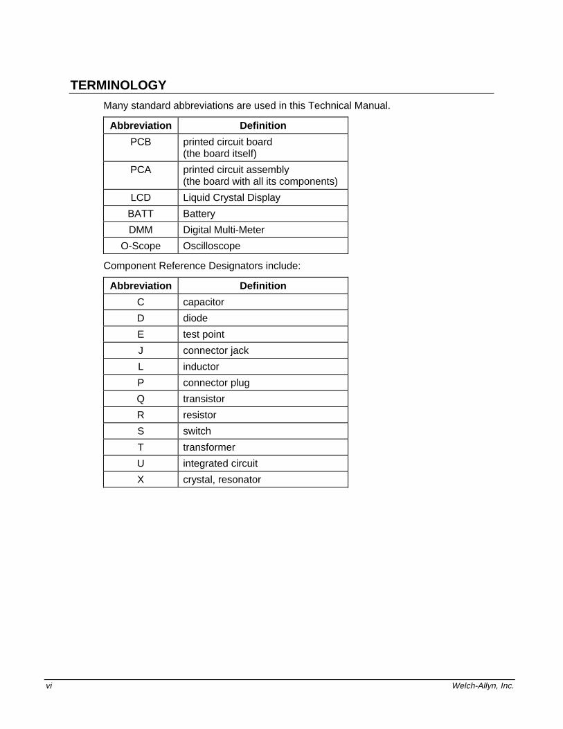
TERMINOLOGY
Many standard abbreviations are used in this Technical Manual.
Abbreviation Definition
PCB printed circuit board(the board itself)
PCA printed circuit assembly(the board with all its components)
LCD Liquid Crystal Display
BATT Battery
DMM Digital Multi-Meter
O-Scope Oscilloscope
Component Reference Designators include:
Abbreviation Definition
C capacitor
D diode
E test point
J connector jack
L inductor
P connector plug
Q transistor
R resistor
S switch
T transformer
U integrated circuit
X crystal, resonator

SureTemp® Model 678/SureTemp® Model 679 1-1
1. OPERATIONAL CHARACTERISTICS
Note: This manual describes both the Model 678 and the Model 679 thermometers.The bulk of the discussion is equally applicable to both products. Where thereare differences, it will be noted as to which instrument the discussion applies.
The Welch Allyn Model 678 and 679 Thermometers are the next generation ofthermistor based medical grade thermometers providing the accuracy and ease of useof thermistor technology as in the well known Model 675. The Model 678 and Model679 provide a Normal mode oral temperature in about 4 seconds, significantly fasterthan the typical 30-40 second average time to temperature in earlier products.
Basic end user operation of the Model 678 and Model 679 is covered in the User’sManual and this manual assumes an understanding of these operations. This chapterwill help you determine if the Model 678/679 is functioning properly and, if it is not,refer you to the proper section to isolate the problem.
Note: There are many things that can be done to check operation before the unit isdisassembled. This section will cover these normal operating actions.
Basic System Description
The thermometer system consists of five main components: The batteries, thethermometer instrument, the wall mount, the probe and the probe cover.
1. Probe cover box 6. Probe Handle2. Display 7. Probe storage well3. Timer button (678 only) 8. Probe connector receptacle4. Mode button 9. Probe cover storage well/ Battery cover5. Probe cover ejection button
Figure 1 - Thermometer Diagram

Technical Manual
1-2 Welch-Allyn, Inc.
Batteries The Model 678 and Model 679 thermometers use three standardalkaline “AA” cells. These batteries are readily available andprovide long life for reduced down time. No battery charging isrequired.
Note: The use of Ni-Cad rechargeable batteries is allowed. Thenominal cell voltage of 1.2 volts for Ni-Cad (vs. 1.5 volts foralkaline) combined with the lower actual capacity thanalkaline will result in a much shorter time between batterycharges than alkaline battery life.
Instrument The main instrument operates very similarly to the Model 675.Basic operation has been kept similar to that of the Model 675 toease learning and use.
Wall Mount The wall holder is easily secured to a wall (or rolling stand). Anoptional locking mechanism with a removable key for securing theinstrument is available. Through the use of available long probecords, the thermometer can be used without removing it from thewall holder.
Probe The probe is similar to earlier probes. Model 670/675 probesare incompatible with Model 678/Model 679 instruments, butModel 767 and Welch Allyn Vital Signs Monitor probes can beused in Model 678/Model 679 thermometers.
Probe Covers The probe covers are unchanged from previous models and arecompatible across all Welch Allyn and Diatek thermistor basedthermometers.
Welch Allyn’s thermistor-based probes can be identified by colorcombinations as indicated in the following table.
HandleColor
TopColor
CordColor
ConnectorColor
Model # ProbeType
Green Green Green or Black Green M600 Oral
Red Red Green or Black Green M600 Rectal
Green Green Green Modular Phone style M650 Oral
Red Red Green Modular Phone style M650 Rectal
White Blue White Blue M670/M675 Oral
White Red White Red M670/M675 Rectal
White Blue White White with latch M678/679/767 Oral
White Red White White with latch M678/679/767 Rectal

Operational Characteristics
SureTemp® Model 678/SureTemp® Model 679 1-3
Self Tests
Instrument Reset/Self Tests
If a problem is reported with an instrument, it is preferred that the user investigateoperation before the unit is reset. However, resetting the electronics is therecommended starting point in the checkout process.
The batteries must be removed from the instrument to reset the internalmicroprocessor electronics. Follow the battery removal instructions in the PreventiveMaintenance section.
Caution: After battery removal, any remaining charge due to internalcapacitance must be discharged to achieve a proper reset. After thebatteries are out, press the Mode or Timer button for about 5 seconds.The electronics will now properly reset upon new battery installation.
1. Remove the probe from the probe storage well and unplug the probe connectorfrom the instrument by depressing the locking tab and pulling on the connectorbody. Do not pull on the cord.
2. While watching the display, install the batteries per the instructions in thePreventive Maintenance section and observe the power up self test.
The self test includes several internal microprocessor self tests, instrument electronicstests and the display test. If there are internal electronics problems detected by theself tests, the error “|X|” icon will be displayed and an audible tone will sound. Referto the Error Codes in the Troubleshooting section for an explanation.
Display Test
The display test begins with each display segment and icon being individually lit inbrief and rapid succession. Immediately after this, all display segments and icons aresimultaneously illuminated briefly followed by a display of the software revision in thisinstrument. The beeper also briefly sounds at the beginning of the test. At the end ofthe test, the display goes blank.
Figure 2 - M678 Display
Note: If a probe is installed during this power up time, the probe type will be displayedas the last item before the display blanks. At this point, there should be noprobe connected to the instrument.
If there is no display, any missing segments, or no beeper, refer to theTroubleshooting section.
Technical Manual
1-4 Welch-Allyn, Inc.
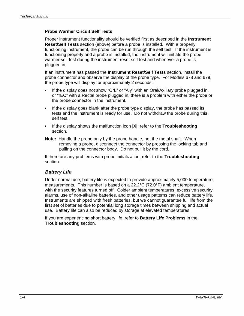
Probe Warmer Circuit Self Tests
Proper instrument functionality should be verified first as described in the InstrumentReset/Self Tests section (above) before a probe is installed. With a properlyfunctioning instrument, the probe can be run through the self test. If the instrument isfunctioning properly and a probe is installed, the instrument will initiate the probewarmer self test during the instrument reset self test and whenever a probe isplugged in.
If an instrument has passed the Instrument Reset/Self Tests section, install theprobe connector and observe the display of the probe type. For Models 678 and 679,the probe type will display for approximately 2 seconds.
• If the display does not show “OrL” or “Aly” with an Oral/Axillary probe plugged in,or “rEC” with a Rectal probe plugged in, there is a problem with either the probe orthe probe connector in the instrument.
• If the display goes blank after the probe type display, the probe has passed itstests and the instrument is ready for use. Do not withdraw the probe during thisself test.
• If the display shows the malfunction icon |X|, refer to the Troubleshootingsection.
Note: Handle the probe only by the probe handle, not the metal shaft. Whenremoving a probe, disconnect the connector by pressing the locking tab andpulling on the connector body. Do not pull it by the cord.
If there are any problems with probe initialization, refer to the Troubleshootingsection.
Battery Life
Under normal use, battery life is expected to provide approximately 5,000 temperaturemeasurements. This number is based on a 22.2°C (72.0°F) ambient temperature,with the security features turned off. Colder ambient temperatures, excessive securityalarms, use of non-alkaline batteries, and other usage patterns can reduce battery life.Instruments are shipped with fresh batteries, but we cannot guarantee full life from thefirst set of batteries due to potential long storage times between shipping and actualuse. Battery life can also be reduced by storage at elevated temperatures.
If you are experiencing short battery life, refer to Battery Life Problems in theTroubleshooting section.
Operational Characteristics
SureTemp® Model 678/SureTemp® Model 679 1-5
Normal Mode
After instrument and probe warmer self tests, the system is ready for use. Normalmode operation is the rapid mode of temperature taking. This is the default mode andis automatically selected when the probe is withdrawn from the probe well.
1. Upon withdrawal of the probe from its storage well, every segment on the displaywill be illuminated. Watch for the display to change from the all segments test tothe probe type display; “OrL/Aly” or “rEC”, depending on the probe and algorithmtype , followed by °C or °F, whichever is selected. This display might take severalseconds to appear. At the same time that the probe type is displayed, a shortbeep will sound.
2. At this point, load a probe cover and take a temperature.
To change between the Oral and the Axillary algorithms; place the instrument inReady mode as described above, and press the Mode button for approximately twoseconds. Observe that the display changes between “Orl” and “Aly” every time theMode button is pressed for more than two seconds.
Note: It is possible that the display will switch from the probe type display to the“walking segments” display and back again several times before the probe isinserted in the mouth. This is acceptable operation and will not adverselyeffect the temperature taken.
The thermometer will automatically switch to Monitor mode under some conditions.These are:
• If the prediction algorithm has not been activated for more than 60 seconds aftertaking the probe out of the storage well.
• If the instrument determines that room temperature is above 33.9°C (93.0°F).
• If the thermometer is unable to predict an oral temperature after 15 seconds dueto improper technique such as excessive probe movement.
With correct use, the patient’s temperature will be displayed in about 4 seconds forModel 678 and for Model 679. The instrument will beep to signal completion of theNormal mode temperature cycle.
Note: The thermometer reads the probe temperature immediately upon removal fromthe storage well. If the probe was just placed into the storage well from aprevious temperature and immediately extracted, insufficient time may havepassed to allow the probe to cool to room temperature. This will result in theinstrument determining room temperature to be higher than actual. This couldresult in the instrument switching to Monitor mode immediately if it detectsroom temperature to be above 33.9°C (93.0°F). For best results, the usershould wait at least 30 seconds between Normal mode temperatures.
If the probe is left out of the storage well after completion of a Normal modetemperature, the unit will shut down after 30 seconds to conserve power. Simplyreplace the probe in the storage well to prepare for the next temperature.

Technical Manual
1-6 Welch-Allyn, Inc.
Monitor Mode
The instrument can be placed in Monitor mode by pressing and holding the Modeswitch for two seconds after a predictive (normal) temperature has been taken. Thismode will be indicated on the display by a capital M in the bottom right corner. Monitormode provides a direct readout of the probe temperature.
This mode of operation has the ability to provide long term monitoring of a patient’stemperature. Unlike Predictive mode, Monitor mode will follow a temperature as itrises or falls.
The typical slow rise in temperature when Monitor mode is used is due mainly to themouth temperature slowly recovering from placement of the colder (roomtemperature) probe. The probe itself is actually very fast at rising to the temperatureof its surroundings, usually within a few seconds. Because of this slow mouthrecovery, the recommended time to wait before recording a Monitor mode oraltemperature is 3 minutes. Similarly, the recommended waiting period for an axillarytemperature taken in Monitor mode is 5 minutes.
Monitor mode is also useful in testing the accuracy of the combined probe/instrumentsystem when the probe can be warmed to a known temperature, as with a Welch AllynModel 9600 Calibration Tester or in a circulating water bath.
Note: The instrument will shut off automatically if the probe temperature remainsbelow 28.9°C (84.0°F) or above 42.2 °C (108.0 °F) for more than 5 minutes.
If Monitor mode does not display expected temperatures or exhibits other problems,refer to the Troubleshooting section.
Pulse Timer Mode (Model 678 only)
Pulse Timer mode is activated from a Low Power or Recall mode by pressing theTimer button. Whenever the unit enters the Pulse Timer mode, it will emit an audiobeep at 0, 15, 30, 45 and 60 seconds. The display will then count up one second at atime, “01”, “02”, ..., “60”.
Pulse timer mode will be terminated automatically upon completion of a 60 secondcount and go back to low-power mode. The pulse timer can be shut off at anytimeduring the 0-60 count by pressing the Timer button, the Mode button or removing theprobe from the probe holder. Connecting a probe will also terminate the pulse timer.
If the timer does not work or exhibits other problems, refer to Timer Problems in theTroubleshooting section.
Backlight (Model 678 only)
The backlight is turned on automatically in any mode except Low Power. Once thebacklight is turned on, it will automatically shut off whenever the instrument goes intoLow Power mode.
The backlight provides a display light for use in dark rooms. The LCD is backlit suchthat all readings are clearly readable in a darkened room from a distance of 18 inches.
If the backlight does not work or is showing other problems refer to the BacklightProblems section in the Troubleshooting section.

Operational Characteristics
SureTemp® Model 678/SureTemp® Model 679 1-7
F/C Conversion
When a final temperature is displayed (in Normal, Recall, or Monitor mode), pressingand releasing the Mode button will toggle the temperature between °F/°C.
Note: A recalled temperature will be displayed in whichever scale (°F/°C) is selectedat the time of recall. This can also be changed during display.
If pressing the Mode button does not change the scale of the displayed temperature,refer to Mode Button Problems in the Troubleshooting section.
Temperature Recall
Whenever the instrument is in Low Power or Pulse Timer mode, pressing andreleasing the Mode button will cause the most recent predicted temperature to bedisplayed for 5 seconds. An “A”, “O”, or “R” will be displayed near the lower rightcorner of the LCD, designating Axillary, Oral and Rectal temperatures for the recalledtemperature. Pressing the Pulse Timer button will interrupt the temperature recallfunction.
Note: No Monitor temperatures will be saved for recall. When a temperature isrecalled, the mode in which it was obtained (axillary, oral or rectal) will beshown independent of the present mode.
If the last temperature can not be recalled, refer to Temperature Recall Problems inthe Troubleshooting section.
Biotech Mode
To enter this special program mode:
1. Place the thermometer in the wall holder.
2. Press and hold the Mode button, and at the same time remove the probe from theprobe well.
Press the Mode button approximately 2 seconds to move sequentially through thevarious program categories. Changes within each category can be made bymomentarily pressing and releasing the Mode button.
Upon entering the Biotech mode, the following features and selections becomeavailable. A number is provided in the flag area to indicate which Biotech category isdisplayed.
To exit Biotech mode at any time, insert the probe into the probe well. Replacing theprobe into the probe holder returns the unit to normal operation. The Biotech modewill automatically time out after 5 minutes of inactivity.

Technical Manual
1-8 Welch-Allyn, Inc.
If you cannot enter the Biotech mode, refer to Biotech Mode Problems in theTroubleshooting section.
Function Settings
1. Software Version Observe the display, The display should show “r X.X” where“X.X” is a number such as 2.3. This can be helpful whendiscussing operation with Welch Allyn customer support.Press the Mode button for more than two seconds toadvance to the Default Algorithm.
2. Default AlgorithmOral/Axillary Modes
Three settings are available to set the default predictivealgorithm: oral, axillary or last prediction. To change thedefault algorithm, momentarily press the Mode button toadvance to the next algorithm. The instrument will be placedin the selected algorithm after the probe has been returnedto the probe well. When replacing the batteries, the power-upsetting is the oral predictive algorithm.
Press the Mode button for more than two seconds toadvance to the Battery Voltage.
3. Battery Voltage This section displays the current battery voltage with 10 mVresolution. The battery is considered acceptable if itmeasures higher than 3.4 volts. New batteries shouldproduce 4.5 volts or more. Each thermometer is factorytested for accuracy down to a supply voltage of 2.9 volts. At3.2 volts, the low battery indicator (battery icon) will flash.When the battery voltage is 3.0 volts or less, the low batteryindicator will display without flashing. Three double beepsare generated, followed by a blank display. At this pointtemperature taking is disallowed.
4. Predictive TemperatureCounter
This section displays the count of the number of predictivetemperature actuations that have occurred since last cleared(in 100’s). Replacing the batteries will clear the counter. Thepower-up setting is 0.
5. Anti-Theft TemperatureCounter System(Model 678 only)
The user can select the anti-theft time out based upon apredictive temperature counter that can be set as 0, 25, 50,100 and 200 (0=disabled).
• The unit will not function when the predictive temperaturecounter has reached the user set parameter. The unit willdisplay a warning consisting of a digit representing thelast 5 counts (i.e. 5,4,...1,) and will display “SEC” on theLCD for five seconds when the probe is returned to thestorage channel after the temperature is complete orafter 30 seconds with the final temperature displayed.
• When the unit enters the alarm state, it will double beepfor approximately 10 seconds and display “SEC” on theLCD. This function is deactivated at power-up.

Operational Characteristics
SureTemp® Model 678/SureTemp® Model 679 1-9
6. Instant Anti-TheftAudio Alarm System(Model 678 only)
The user can select an anti-theft option that instructs theinstrument to beep continuously (beginning afterapproximately 5 seconds) whenever the unit is removed fromthe wall holder.
• The user must defeat the Instant Anti-Theft Audio Alarmwithin 30 seconds after removal from the wall holder byholding the Mode button and removing the probe fromthe probe well, or by returning the unit to the wall holder.
• After 30 seconds, the instrument must be returned to thewall holder to silence and reset the Instant Anti-TheftAudio Alarm.
• Once in the Instant Anti-Theft Audio Alarm state, theinstrument will continue the audio alarm until power isexhausted or until the unit is returned to the wall holder.
Note: At power-up, this mode is deactivated.
7. Error Log (Function 5in the Model 679)
The instrument will save the last 10 error messages thatoccur and display those messages in a last in first viewedsequence. While in error log, the display reads E x.x. Todisplay the next error, momentarily press the mode button.
Note: Battery removal will clear the error log of all errormessages.

Technical Manual
1-10 Welch-Allyn, Inc.

SureTemp® Model 678/SureTemp® Model 679 2-1
2. PREVENTIVE MAINTENANCE
The following preventive maintenance is recommended to maximize uninterruptedservice with the M678 and M679 SureTemp Thermometers. Units which are in serviceon a regular basis should have the following preventive maintenance performed every6 months:
1. Visually inspect the thermometer for physical damage which might cause futureproduct failure.
2. Clean the unit per instructions in the Directions for Use manual supplied with thethermometer and/or per the instructions below.
3. Perform the Power-Up Display test, Startup Display test and Model 9600Calibration Testing procedure found in the Model 9600 Operation Manual.
Units which are stored for an extended period and not used should have the followingperformed every 12 months:
1. Replace the batteries according to the procedures found in the Directions for Usemanual.
2. Perform the Power-Up Display test, Startup Display test and Model 9600Calibration Testing procedure found in the Model 9600 Operation Manual.
Cleaning and Sterilization
Routine Cleaning
Clean the exterior of both the Model 678 or Model 679 instrument, the wall mount andthe probe as needed. Wipe all surfaces with a clean cloth dampened with warm waterand a mild detergent, alcohol, or a nonstaining disinfectant such as Sporicidin Sprayand Towelettes1 or MetriSpray cleanser2. Care should be taken to not scratch theLCD faceplate. Make sure that the cloth is damp, but not too wet.
Note: Do not allow cleaning solution to run inside the instrument. Never immerse thethermometer into the cleaning solution. Never autoclave the thermometer orprobe.
ETO Gas Sterilization Procedure
When no other form of decontamination such as a germicidal wipe is acceptable, alow temperature (not to exceed 48.9°C [120°F]) ETO gas sterilization cycle may beused. Refer to your institution’s standard operating procedure for the length of thecycle.
1 Sporicidin is a registered trademark of Sporicidin International (800) 424-3733.2 MetriSpray is a trademark of Metrex Research Corporation (800) 841-1428.

Technical Manual
2-2 Welch-Allyn, Inc.
This type of sterilization may cause some hazing of glossy plastic surfaces and shouldbe used only when absolutely necessary.
1. Ensure that the probe is removed from its storage well and disconnected from theinstrument.
2. Remove any probe covers from the probe and from the probe cover storage well.
3. Remove the batteries following the instructions in the Battery Removal andReplacement section below.
WARNING: Leaving batteries in the thermometer during the sterilizationprocedure may present an explosion hazard.
4. Wrap the thermometer in a standard sterilization type packaging such as theBaxter Tower Dualpeel Sterilization Pouch.
5. ETO gas sterilize at a temperature not to exceed 48.9°C (120°F) and aerate.
6. Remove the sterilization packaging.
7. Before installing the batteries and probe, allow the probe and instrument tostabilize to room temperature for at least one hour.
8. Reinstall the batteries (see Battery Removal and Replacement below) and verifya successful self test.
9. Install the probe connector and insert the probe into the storage well to start theprobe initialization process.
10. Verify proper calibration of the thermometer and probe using the Welch AllynModel 9600 Calibration Tester.
Battery Removal and Replacement
1. Using a flat surface, lay the thermometer on its front panel.
2. Remove the PROBE COVER BOX HOLDER on the back of the instrument bypressing with thumb and middle finger on the “dimples” located in the sides ofPROBE COVER BOX HOLDER . The batteries are located under the PROBECOVER BOX HOLDER .
3. Remove the batteries by pulling on the ribbon located under them.
4. Press either the Mode or the Timer button for approximately five seconds todischarge the electronics.
5. Install 3 new “AA” batteries according to the battery polarities marked inside thebattery compartment. Verify that the thermometer completes self-test, then goesblank.
CAUTION: Incorrect battery polarity may result in damage to the thermometer.
6. Reinstall the PROBE COVER BOX HOLDER .
SureTemp® Model 678/SureTemp® Model 679 3-1
3. CALIBRATION TESTING
The Calibration Key provides a convenient means of testing the thermometer.
Calibration Key Procedure
1. Extract the probe and disconnect it from the thermometer.
2. Insert the Calibration Key (part number 01637-000) into the probe connectorreceptacle on the thermometer and observe the display. The display should readCAL for two seconds, and then go blank.
3. Insert a probe shaft into the probe storage well and remove it to initiate atemperature taking cycle. Wait for the display test and then observe the display.The display must read between 97.1°F and 97.5°F inclusive for the calibration ofthe instrument to be correct.
4. Remove the Calibration Key and reinstall the probe connector plug.
5. Then install the probe into the probe storage well.
Note: This Cal Key test does not test the probe. To do so requires the use of theWelch Allyn Model 9600 Calibration Tester.
If the reading from the Cal Key is not within the specified range or you are havingother problems with the use of the Cal Key, refer to Cal Key Problems in theTroubleshooting section.
Model 9600 Calibration Testing Procedure
The Model 9600 Calibration Tester provides a convenient means of testing the entirethermometer system (instrument and probe).
• The 9600 must be warmed up and stable at one of the two available temperaturesettings.
• The thermistor based instrument under test must be in Monitor mode and no probecover loaded.
The probe is inserted into the small hole in the dry heat well of the 9600 and allowedto settle for a minimum of 2 minutes to the final temperature. The reading on thethermometer must be within the range specified on the 9600. Refer to the Model 9600Operation Manual for complete instructions.
Note: All Welch Allyn and Diatek thermometers (thermistor and infrared earthermometers) can be checked in the Model 9600.
If you are having problems with the use of the Model 9600, refer to theTroubleshooting section in the Model 9600 Operation Manual.

Technical Manual
3-2 Welch-Allyn, Inc.
SureTemp® Model 678/SureTemp® Model 679 4-1
4. THEORY OF OPERATION
Technical Overview
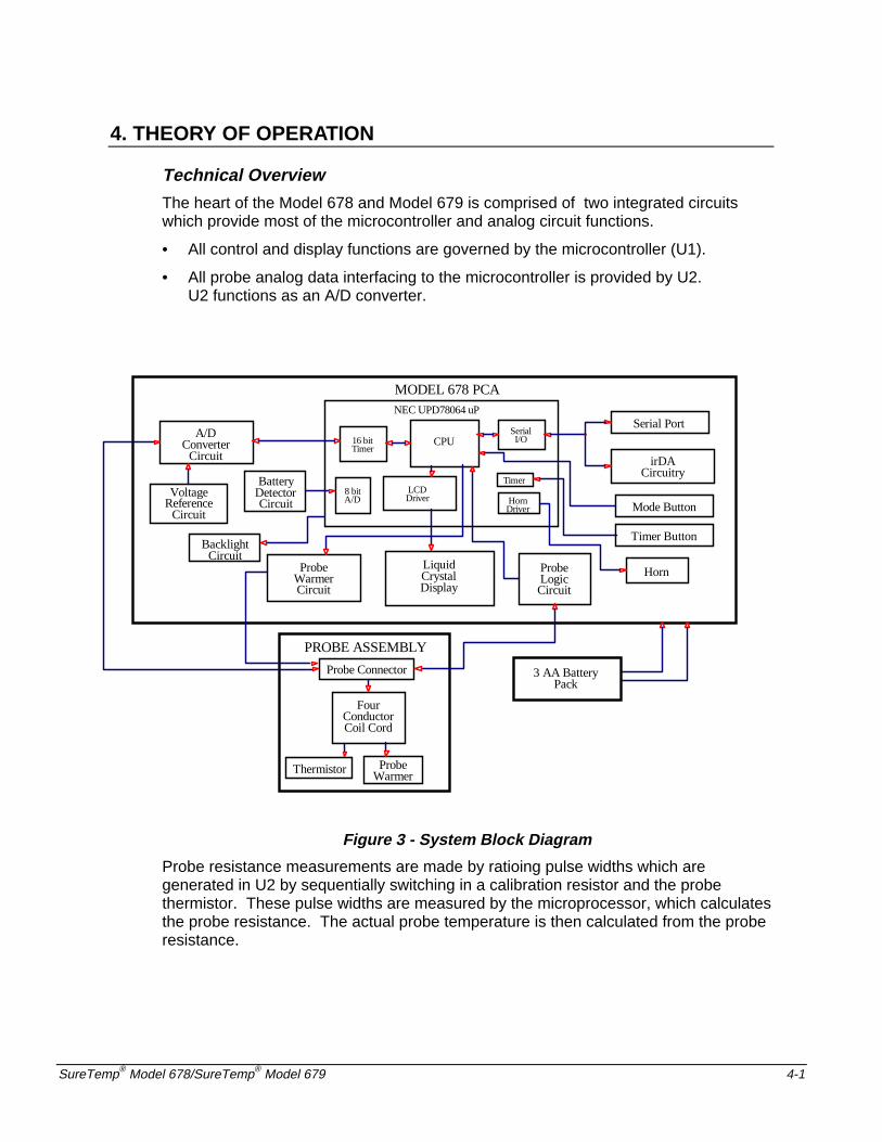
The heart of the Model 678 and Model 679 is comprised of two integrated circuitswhich provide most of the microcontroller and analog circuit functions.
• All control and display functions are governed by the microcontroller (U1).
• All probe analog data interfacing to the microcontroller is provided by U2.U2 functions as an A/D converter.
NEC UPD78064 uP
16 bitTimer
HornDriver
Timer
CPU
MODEL 678 PCA
A/DConverterCircuit
VoltageReference
Circuit
LCDDriver
SerialI/O
Serial Port
irDACircuitry
ProbeWarmerCircuit
LiquidCrystalDisplay
Mode Button
Timer Button
PROBE ASSEMBLY
ProbeWarmer
Thermistor
FourConductorCoil Cord
Probe Connector 3 AA BatteryPack
ProbeLogicCircuit
Horn
BacklightCircuit
BatteryDetectorCircuit
8 bitA/D
Figure 3 - System Block Diagram
Probe resistance measurements are made by ratioing pulse widths which aregenerated in U2 by sequentially switching in a calibration resistor and the probethermistor. These pulse widths are measured by the microprocessor, which calculatesthe probe resistance. The actual probe temperature is then calculated from the proberesistance.
Technical Manual
4-2 Welch-Allyn, Inc.
Probe Enhancements
The Model 678 and Model 679 thermometers have the capability to detect probe type -oral / axillary vs. rectal. This allows the oral temperature-taking to be as fast aspossible by using different operating modes based on probe type. Axillarytemperatures are measured with oral probes in combination with the axillary mode,providing a temperature reading in about 15 seconds. Rectal probes give a Normalmode temperature in about 15 seconds for both models.
Probe type recognition also allows the use of minor differences in predictionparameters tailored to the temperature taking site to help increase speed overprevious products.
The probe type is communicated to the thermometer by the use of shorting jumpersbetween the ground and two of the probe connector contacts. Model 678 / 679oral/axillary probes also incorporate a warming resistor in the tip to pre-warm theprobe before placement in the mouth or axilla, thus speeding response even further.
Probe Switch
The probe switch (S4) is activated by the probe shaft when the probe is installed orremoved from its storage well. Placing the probe into the storage well pulls processorpin 15 high via R6. When the probe is removed, this line is pulled low. This signal isalso routed to test connector J4 pin 5 to allow automated testing of this function duringfactory test. R6 allows this line to be pulled high or low at J4 during factory testregardless of the actual switch position.
CAUTION: For the technician, J4 serves as a convenient set of “test points”to monitor proper operation of all user switch functions.BE CAREFUL WITH STATIC DISCHARGE! J4 TIES DIRECTLYTO CMOS PROCESSOR INPUTS WHICH ARE EASILY DAMAGEDBY STATIC DISCHARGE. FOLLOW PROPER ESD HANDLINGTECHNIQUES.
Normal Mode
The Oral/Axillary probe is pre-warmed using a pulse width modulation (PWM)controller to 33.9°C (93°F) upon extraction from the storage well.
• When the probe is first extracted and colder than 33.9°C, the heater pulse widthsare at a maximum percentage ON vs. OFF to warm the probe quickly.
• When the probe reaches 33.9°C, the pulse widths narrow to a duty cycle justenough to maintain temperature.
• When the probe is placed in the mouth, the heat supplied by the mouth makes thepulse widths reduce to zero. This reduction to zero (and the probe being at leastup to 33.1°C / 91.6° F) triggers the start of the prediction algorithm.

Theory of Operation
SureTemp® Model 678/SureTemp® Model 679 4-3
The shape of the rising temperature curve is monitored and the best fit to a curve isfound. When the curve fit is stable, the final predicted temperature is displayed.
• In the oral mode, if the prediction criteria is not met within 15 seconds of startingthe prediction process, it will automatically switch to Monitor mode.
• In the axillary mode, if the prediction criteria is not met within 30 seconds ofstarting the prediction process, the thermometer displays a final temperature butalso indicates that the probe is out of position.
• In the oral or axillary mode, if the ambient temperature is above 33.9°C (93.0°F)the unit will automatically switch to Monitor mode.
• Rectal probes are not prewarmed. Rectal temperature measurements will takeabout 15 seconds.
• Within 60 seconds after the probe is removed from the well, if the predictionprocess has not started, the thermometer will switch to Monitor mode.
Power Supply
The Model 678 contains a battery pack made up of 3 AA size batteries. This providesa maximum supply voltage of about 4.8 volts. Power is drawn from the three AAalkaline cells directly to the circuit electronics. The voltage from the batteries isunregulated but filtered by capacitor C25. The power supply voltage will range fromabout 4.8 volts with new batteries to 3.0 volts at shut down.
The thermometer has two low battery voltage indications.
• The first is a warning that batteries are getting low and is indicated by the batteryicon flashing in the display. This begins when the batteries fall to about 3.2 volts.Accuracy is not affected during low battery warning indication.
• When the batteries fall to approximately 3.0 volts, the low battery error condition isdefined to exist. Operation is halted and the E2.1 error message is stored inmemory. At this point, the batteries must be replaced and the thermometerelectronics reset. See Reset Self/Tests on page 4 and on page v.
Low Battery Detection
The Model 678 includes a low battery detector circuit which shuts the device off whenthe battery degrades to 3 volts. This ensures that erroneous temperature readingsare not given due to a low battery. For this operation, the reference voltage (VREF) ismeasured by software using channel 1 of the 8 bit A/D in the microprocessor. TheA/D is powered with the battery voltage (VCC) through Q12. A/D channel 1 iscompared to the full scale on the A/D. As the battery voltage gets lower, channel 1readings get higher. A reading above a fixed limit indicates a weak battery.Exceeding another limit indicates a dead battery and the device will shut off.
Microcontroller
A NEC UPD78064 or UPD78063 single chip microcontroller in a QFP package (U1) isused for signal digitizing, data processing, program memory addressing and storage,and I/O interfacing. The microcontroller also includes an LCD controller/driver whichallows internal conversion of CMOS logic levels to a data format capable of driving theModel 678/679 LCD. In this application, the microcontroller is running atapproximately 2.5 MHz, which is achieved by using a 4.9152 MHz Crystal (X1).
Technical Manual
4-4 Welch-Allyn, Inc.
Reset/Self Tests
Upon battery installation, (assuming that the electronics have been dischargedsufficiently by pressing a user button with batteries removed) the microprocessorreceives a power up reset signal from the components associated with the reset line atU1-12. When power is applied continuously, C3 is charged slowly through R7,providing an active low reset to the microprocessor.
When the reset signal is complete, the microprocessor launches a series of selfchecks which include RAM test, ROM test, instruction set test, self calibration tests(electronics accuracy test, hi cal, low cal), probe warmer circuitry tests, probe test,battery voltage test and ambient temperature test. Any failures here will cause aspecific error code to be displayed to assist debugging.
Microprocessor Clock
The clock for the microprocessor is generated by X1 and capacitors C26 and C27,which form a 4.9152 MHz. oscillator circuit. The microcontroller is running atapproximately 2.5 MHz, which is achieved by internally dividing the frequency ofoscillation by two.
Temperature Measurement and Display
The thermometer probes incorporate negative temperature coefficient thermistors.When the temperature of the probe is increased, its electrical resistance decreases.Model 678 and 679 use “20K” thermistors, so they are at approximately 20 Kohms atroom temperature. At 37 °C (98.6 °F) they are near 12 Kohms. The change inresistance is nonlinear with temperature, and an equation describing this curve isprogrammed into the thermometer.
Temperature Measurement A/D Converter
The primary function of the temperature measurement A/D converter circuit is toconvert a measured resistance into a 16-bit word, which is then used by themicroprocessor to calibrate itself and calculate a temperature.
Theory of Operation
The A/D circuit is made up of 4 major parts:
• The resistance to be measured (either the probe thermistor, the PTBCAL resistor,or the HICAL resistor).
• The timing capacitor (C21, 0.33uF) and associated driver circuitry(Q1-Q4, Q9, R15, and R30).
• A low bias dual voltage comparator (U2, TLC555).
• A 16 bit timer internal to the microprocessor.

Theory of Operation
SureTemp® Model 678/SureTemp® Model 679 4-5
In effect, this is a single slope converter which measures the time constant of themeasured resistance combined with a fixed capacitance. The time constant ismeasured by counting the time it takes for the voltage to decay from a fixed initialvoltage level to a fixed lower voltage. The ratio of this pulse width and the pulse widthcorresponding to a known calibration resistance (R13, 11.55K) is used to calculate themeasured resistance. Once the resistance is known, the corresponding temperatureis calculated using the thermistor temperature equation. Because the M678 uses this‘ratio cal’ method for measuring the thermistor resistance, the device is immune to anumber of gain errors which can be measured and corrected using software.
Circuit Description
Initially, the microprocessor simultaneously discharges both sides of the capacitor.This is accomplished by bringing A/D TRIGGER high which turns on Q9, pulling oneside of capacitor C21 to ground. This also turns on Q1, Q2, and Q3 via PROBE_SEL,PTBCAL_SEL, and HICAL_SEL, which allows the other side to discharge through thethermistor R8(12.1K) and R13(11.55K).
Once capacitor C21 has been fully discharged, the probe thermistor is then selectedby switching the PTBCAL and the HICAL resistor paths off. The microprocessor thenforces the A/D TRIGGER signal to go low turning on Q4, which lifts one end ofcapacitor C21 up to VREF(2.4v).
Because there can be no instantaneous voltage drop across capacitor C21, the otherside of the capacitor immediately goes to 2.4v. This exceeds the thresholdvoltage(1.6v) of U2(TLC555), causing the output A/D_OUT to go low. At this point,the capacitor begins to discharge from 2.4v to 0v through the thermistor resistor.
The output of the comparator goes high again when its input reaches the triggervoltage(0.8 volts). This produces a pulse of length equal to the time it takes for thecapacitor to discharge from 1.6v to 0.8v through the thermistor.
The microprocessor measures this pulse width using an internal 16-bit timer and thenthe same A/D conversion is performed using the HICAL resistor as the measurandresistance. The microprocessor performs the following calculation that ratios thesetwo pulse widths to determine the exact resistance of the thermistor:
Rthermistor
.( )PWthermistor ( )Rhical
PWhical
The microprocessor then uses the following equation to convert the measuredresistance into a temperature:
Temperature_in_Kelvin1
Ra .Rb ln ( )Rt .Rc ( )ln ( )Rt3
Technical Manual
4-6 Welch-Allyn, Inc.
Q4 and Q5 and the base resistors R15 and R30 form the level shifter and drive circuitfor the fixed end of the timing capacitor. R15 (4.7K) is selected to give adequatesaturation on-resistance. R30 (10K) is selected so that a float on the input will notcause damage from cross-conduction if the input is left floating, yet supply enoughcurrent to the timing capacitor during recovery. Q4 and Q9 exhibit only a few millivoltsof saturation voltage, which does not affect the accuracy of the A/D as describedabove.
• C21 is the surface mount timing capacitor. This capacitor is selected for lowdielectric absorption, hence the high voltage rating (50V).
• D4 and R16 protect the comparator from input undervoltage when the timingcapacitor (C21) is discharged. D4 also reduces the recovery time by limiting thevoltage at the beginning of recovery to 0.6 volts instead of 2/3VREF.
• C5 provides the first line of defense from EMI (Electro Magnetic Interference)coming in on the probe. R33 and C18 protect Q1 from rectifying EMI in thesubstrate diode. R16 protects the comparator input from overcurrent.
Probe Identification Logic
Basic Function
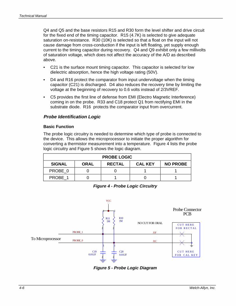
The probe logic circuitry is needed to determine which type of probe is connected tothe device. This allows the microprocessor to initiate the proper algorithm forconverting a thermistor measurement into a temperature. Figure 4 lists the probelogic circuitry and Figure 5 shows the logic diagram.
PROBE LOGIC
SIGNAL ORAL RECTAL CAL KEY NO PROBE
PROBE_0 0 0 1 1
PROBE_1 0 1 0 1
Figure 4 - Probe Logic Circuitry
PROBE_1
PROBE_0
VCC
1
2
R101M
1
2
R111M
1
2
C190.01UF
1
2
C200.01UF
J1F
J1C
C U T H E R EF O R R E C T A L
C U T H E R EF O R C A L K E Y
Probe ConnectorPCB
To Microprocessor
NO CUT FOR ORAL
Figure 5 - Probe Logic Diagram

Theory of Operation
SureTemp® Model 678/SureTemp® Model 679 4-7
Circuit Operation
R10, R11 (both 1 MΩ pullup resistors to reduce battery drain), J1-F(PROBE_1), J1-C(PROBE_0) and J1-E(GND) are used to provide logic 0 or 1 inputs to U1-17 and U1-18 depending on whether a probe or cal key has been plugged into the Model 678probe connector receptacle. When a probe has been plugged in, the softwaredetermines whether it is Oral, Axillary, Rectal, or a Cal Key as follows:
• When J1-C (CAL) and J1-F (RCTL) are both connected to J1-E (GND) (byjumpers installed in the Model 678 probe PCB), the software determines that theprobe is an Oral probe;
• When J1-C (CAL) is connected to J1-E (GND), but J1-F (RCTL) is not connectedto J1-E (GND), the software determines that the probe is Rectal probe;
• When J1-F (RCTL) is connected to J1-E (GND), but J1-C (CAL) is not connectedto J1-E (GND), the software determines that the probe is a Calibration Key;
• When neither J1-C (CAL) or J1-F (RCTL) are connected to J1-E (GND), the softwaredetermines that no probe has been plugged in.
C19 and C20, both 0.01 uF capacitors, are bypass capacitors used to filter outspurious noise to the microprocessor on the probe input lines J1-F(PROBE_1) andJ1-C(PROBE_2).
Probe Warming ( Oral probes only)
Probe characteristics vary somewhat due to normal production process variations. Itis desirable to warm the probe as efficiently as possible from a time-to-readystandpoint and from a temperature stability standpoint when the probe is up totemperature.
The probe warming process is a closed loop feedback control system incorporatingPWM (pulse width modulation) control.
The probe warmer circuitry is used to heat the probe tip prior to taking a temperaturereading in order to speed the convergence of the prediction algorithm. This allowsquicker temperature readings. A fail safe hardware shutoff circuit is included to ensurethe heater will shut off in the event of a software failure.
Theory of Operation
The microprocessor sends pulses via /HTRC to drive the probe heater resistor whichheats the probe tip. A temperature of about 93°F is maintained prior to taking atemperature.
A software algorithm calculates the width of the HTRC pulse as a function of thedifference between the probe temperature and 93°F, and as a function of the probetemperature rate of change. It provides an initial pulse to rapidly heat up the probe tip tothe 90°F region and then supplies progressively shorter pulses as the probe temperatureconverges to about 93°F. Once 93°F is reached, software continues to send a “control”pulse to maintain the temperature.

Technical Manual
4-8 Welch-Allyn, Inc.
Circuit Operation
The warmer circuitry consists of Q5, Q13, Q14, C1, C2, L1, D1, R1, R2, R3, R4, R5,R31, R32, and the heater resistor (27 ohms) connected across J1B and J1E.
Line /HTRQ is pulled low by the uP which enables Q13 to turn on. /HTRC is then pulsedlow which brings the base of Q5 low via capacitor C1. Q5 turns on which in turn enablesQ14 on. Base current from Q14 flows through R31 (1K) and R32 (1K). Most of thiscurrent flows through the emitter of Q5 while some flows through R1 (470K) to satisfy thediode drop of Q5’s BE junction. The base current of Q5 along with the current throughR1 flows into C1(1uF), charging it up. This sets up the mechanism for the hardwareshutoff. As this capacitor charges up, the base voltage of Q5 approaches the emittervoltage and the transistor shuts off, thereby shutting down the probe warmer. As long asQ5 remains on, Q14 has a base current flowing which allows current to flow from itscollector through R2 (4.7K) and the heater resistor. With about 150mA flowing through it([VCC-2VCEsat]/29 ohms), the heater resistor heats up the probe tip.
During normal operation, software turns the warmer circuit on and off. The width of thepulse on HTRC determines how long Q5 is turned on, thereby determining how long theheater is heating. Once the HTRC pulse goes high again, the base of Q5 is pulled highturning it off, and the capacitor discharges to VCC through D1.
Q13 and Q14 are selected for their low saturation on voltage. D1 is a diode clampused to keep the base of Q5 from attaining a much higher voltage than VCC. R4(47K)and R2(4.7K) in combination with R3(47K), serve as pull down resistors ensuring thatthe processor feedback lines (U1-34 and U1-35) go low immediately upon warmercomponent shut off. C2 serves as an RFI suppression component.
Other Components
Liquid Crystal Display
The model 678 and Model 679 use a liquid crystal display to display data to the user.Three communication lines and 18 segment lines connect the LCD to the displaydriver (U1-60 to U1-80) internal to the NEC microprocessor. The LCD is 3:1multiplexed with 1/2 bias. The bias voltages (1.5 volts, and 3.0 volts) are supplied tothe display driver by the voltage reference circuit
The LCD glass is electrically tied to the display PCB via an elastomeric connectorsandwiched and compressed between the glass and the PCB by the frame. Thisassembly, if taken apart, cannot be reassembled without replacing the frame.
LCD Backlight (Model 678 Only)
The backlight is a low power LED which illuminates the back of the LCD display. Thebacklight will be turned on automatically in any mode except Low Power. Once thebacklight is turned on, it will automatically shut off whenever the instrument goes intoLow Power mode.
Battery power is applied to current limiter resistor R23 and LED D3. Whenmicroprocessor signal /BLIGHTCTL at pin 42 goes low, current is allowed to flowthrough the LED. The amount of current is approximately 2 milliamps, depending onthe Battery voltage Vcc. When the instrument is in Low Power mode / BLIGHTCTLgoes high, turning the LED backlight off to conserve power.

Theory of Operation
SureTemp® Model 678/SureTemp® Model 679 4-9
Probe Switch
When the probe has been inserted in the probe holder, the probe switch (S4) bringsPROBE SW (U1-15) high (VCC). When the probe is removed from the probe holder,the probe switch brings PROBE SW (U1-15) low (GND). R6 (47K) allows the probeswitch to be overridden by the test port.
Mode Button
The mode button (S2) is a momentary contact switch. A pullup internal to themicroprocessor normally pulls /MODE (U1-25) high, placing a logic “1” at this input.When depressed, S2 provides a momentary contact to ground at /MODE giving it alogic level of “0”. The software continuously checks /MODE. If the thermometer is notin the process of taking a temperature, pressing the Mode button will wake up thethermometer and display the last recorded temperature.
Timer Button (678 Only)
The timer button (S1) is also a momentary contact switch. A pullup internal to themicroprocessor normally pulls /PTIMER (U1-26) high, placing a logic “1” at this input.When depressed, S1 provides a momentary contact to ground at /PTIMER giving it alogic level of “0”. The software continuously checks /PTIMER.
Serial Communications Port
Transmit , receive data and control CMOS-level signals are made available for test orsystem integration via J4. The contacts of J4 are laid out so they are accessiblethrough a slot in the rear of the case. Communications on a cable length of over onefoot should be driven with external RS232 or other line driving circuitry.
Horn
The horn is activated at the start of a temperature taking cycle, at the end of a Normalmode temperature cycle, during timer operation at 0, 15, 30, 45 and 60 seconds, andfor various error conditions.
• A short duration single beep is indicative of normal operation.
• A short duration double beep is used to indicate errors and warnings such asswitching from Normal mode to Monitor mode during a temperature cycle.
The horn is a piezoelectric ceramic resonator driven by the processor square wave.The horn control signal comes from U1 pin 49. It directly drives the horn LS1.

Technical Manual
4-10 Welch-Allyn, Inc.

SureTemp® Model 678/SureTemp® Model 679 5-1
5. TROUBLESHOOTING
Many thermometer operational parameters can be tested for proper operation beforethe unit is taken apart and without needing any tools. Refer to OperationalCharacteristics on page 1-1 and in particular to the Setup and Biotech Modesections for guidance on preliminary checks.
If the trouble seems to be calibration related, refer to Calibration Testing onpage 3-1.
If these sections do not prove useful in resolving the problem and you are sure thatthe instrument is not performing properly, the following sections should guide youthrough the debugging process given the proper tools and equipment.
Error Codes
Error codes are divided into four classes:
Probe Probe errors are generated by the probe or the probe connector and arenot errors generated by the thermometer. They do require thattemperature measuring be inhibited until the error is cleared. There is nolimit to the number of times a probe error can occur. All probe problemsare considered by the thermometer to be recoverable. When a probe erroroccurs, the probe icon is displayed.
AmbientTemperature
Ambient Temperature errors occur when the ambient probe temperature isabove 104.0° F or below 60.8° F. During an ambient temperature error, thedisplay shows an ”A” with either the up or down arrow icon flashing.
Dead Battery Dead Battery error occurs when the instrument detects a battery voltage of3.0 volts or less. The battery icon is displayed without flashing when thiserror occurs.
InstrumentCircuitry
Instrument Circuitry errors are generated from internal test failures and canbe recoverable or non-recoverable. Error code numbers are only availablein Biotech mode.
• Recoverable errors require that temperature measuring beinhibited until the error is cleared. After displaying the error |X|icon, the instrument will shut itself off and store the error code inmemory.
• Non-recoverable errors are generated from internal ROM andRAM test failures. The error code will be stored in memory andthe LCD will disply the error |X| Instrument Malfunction icon.Theonly way to recover from a ROM or RAM error is to reset theelectronics by removing the batteries.
Note: Error codes E0.1, E0.2, E0.3, can sometimes be caused by a faulty probe. It isadvisable to remove the probe completely from the instrument and check itsfunctionality as described in the Operational Characteristics section before assumingan instrument problem instead of a probe problem. If another probe is available, thiscan prove useful in tracking down the source of the problem.
Technical Manual
5-2 Welch-Allyn, Inc.
70898-0000A
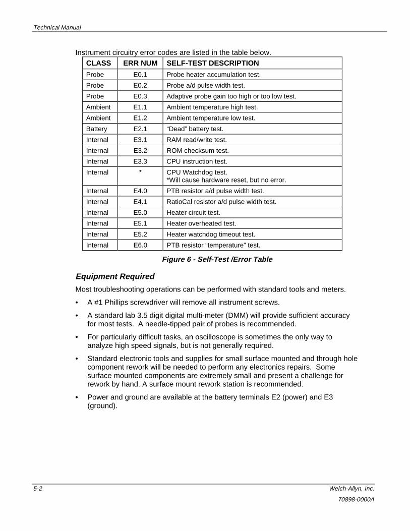
Instrument circuitry error codes are listed in the table below.CLASS ERR NUM SELF-TEST DESCRIPTION
Probe E0.1 Probe heater accumulation test.
Probe E0.2 Probe a/d pulse width test.
Probe E0.3 Adaptive probe gain too high or too low test.
Ambient E1.1 Ambient temperature high test.
Ambient E1.2 Ambient temperature low test.
Battery E2.1 “Dead” battery test.
Internal E3.1 RAM read/write test.
Internal E3.2 ROM checksum test.
Internal E3.3 CPU instruction test.
Internal * CPU Watchdog test.*Will cause hardware reset, but no error.
Internal E4.0 PTB resistor a/d pulse width test.
Internal E4.1 RatioCal resistor a/d pulse width test.
Internal E5.0 Heater circuit test.
Internal E5.1 Heater overheated test.
Internal E5.2 Heater watchdog timeout test.
Internal E6.0 PTB resistor “temperature” test.
Figure 6 - Self-Test /Error Table
Equipment Required
Most troubleshooting operations can be performed with standard tools and meters.
• A #1 Phillips screwdriver will remove all instrument screws.
• A standard lab 3.5 digit digital multi-meter (DMM) will provide sufficient accuracyfor most tests. A needle-tipped pair of probes is recommended.
• For particularly difficult tasks, an oscilloscope is sometimes the only way toanalyze high speed signals, but is not generally required.
• Standard electronic tools and supplies for small surface mounted and through holecomponent rework will be needed to perform any electronics repairs. Somesurface mounted components are extremely small and present a challenge forrework by hand. A surface mount rework station is recommended.
• Power and ground are available at the battery terminals E2 (power) and E3(ground).

Troubleshooting
SureTemp® Model 678/SureTemp® Model 679 5-3
Troubleshooting Table
SYMPTOM POSSIBLE CAUSE PROCEDURE
No operation Dead batteries, no batteries,battery missing, batteryincorrectly installed
Refer to Battery Removal andReplacement on page 2-2. Checkthat all batteries are installed inproper direction.
Reset electronics (see InstrumentReset/Self Tests on page 1-3).
If battery voltage is withinspecifications, refer to BiotechMode on page 1-7 and enterBiotech mode to measure batteryvoltage as seen by electronics.
Broken battery wire Open instrument case, installbatteries, check for voltage onmain PCB at battery wireconnections.
Short circuit preventingoperation
Remove batteries, press modebutton 5 seconds, set DMM toOhms, measure resistance ofelectronics at battery contacts (“+”to bottom right corner, “-” to top leftcorner). Resistance should climbto more than 2 Megohms as C25charges.
Failed component Check oscillator at U1-7 for 4.91MHz sine wave. If not present,suspect X1 or U1.
Display problems LCD frame loose Check that all 4 plastic hooks forthe LCD frame are tight and notbroken. The frame should not belifting off of the PCB.
Dirty LCD elastomericconductor strips
Have a new LCD frame handy.Remove old one by unlatchingplastic hooks. Clean LCDelastomeric strips, LCD glasscontacts, and PCB contacts withlint proof cloth dampened withalcohol.
Technical Manual
5-4 Welch-Allyn, Inc.
70898-0000A
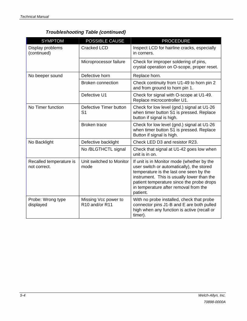
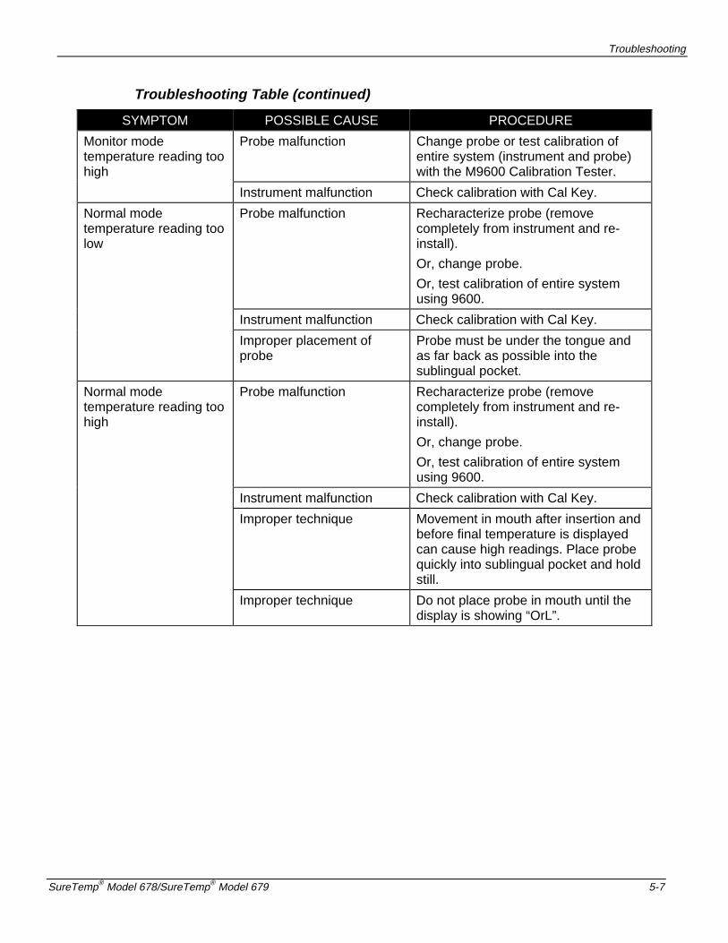
Troubleshooting Table (continued)
SYMPTOM POSSIBLE CAUSE PROCEDURE
Display problems(continued)
Cracked LCD Inspect LCD for hairline cracks, especiallyin corners.
Microprocessor failure Check for improper soldering of pins,crystal operation on O-scope, proper reset.
No beeper sound Defective horn Replace horn.
Broken connection Check continuity from U1-49 to horn pin 2and from ground to horn pin 1.
Defective U1 Check for signal with O-scope at U1-49.Replace microcontroller U1.
No Timer function Defective Timer buttonS1
Check for low level (gnd.) signal at U1-26when timer button S1 is pressed. Replacebutton if signal is high.
Broken trace Check for low level (gnd.) signal at U1-26when timer button S1 is pressed. ReplaceButton if signal is high.
No Backlight Defective backlight Check LED D3 and resistor R23.
No /BLGTHCTL signal Check that signal at U1-42 goes low whenunit is in on.
Recalled temperature isnot correct.
Unit switched to Monitormode
If unit is in Monitor mode (whether by theuser switch or automatically), the storedtemperature is the last one seen by theinstrument. This is usually lower than thepatient temperature since the probe dropsin temperature after removal from thepatient.
Probe: Wrong typedisplayed
Missing Vcc power toR10 and/or R11
With no probe installed, check that probeconnector pins J1-B and E are both pulledhigh when any function is active (recall ortimer).

Troubleshooting
SureTemp® Model 678/SureTemp® Model 679 5-5
Troubleshooting Table (continued)
SYMPTOM POSSIBLE CAUSE PROCEDURE
Probe: Wrong typedisplayed (continued)
Incorrect wiring ofprobe
Oral probes should have a short betweenpins B, E and F (refer to instrument PCBdesignators for probe pin definition).
Rectal probes should have a short betweenpins E and F but open between pins B andE or F.
Replace with new probe.
Normal/Monitor Modeswitching problems
Ambient above 33.9°C(93.0°F)
Causes auto switch to Monitor mode.
Switched to Monitormode before probe inmouth
If 60 seconds pass after ready in Normalmode, unit switches to Monitor mode.
If probe is still cooling from a previoustemperature and used immediately, it mightsense ambient to be above 33.9°C(93.0°F).
Defective Mode button Check mode button for proper function.
Check U1-25 for low level signal whenbutton is pressed.
Deffective Probe Replace probe.
Cannot enter BiotechMode
Mode button notpressed, and orInstrument not in wallholder (678 only)
Mode button must be pressed whileinstrument is in the wall holder.
Probe not connectedand or probe shaft notinserted and removedfrom probe well
Must connect probe to instrument andremove the probe shaft from the probe wellwhile the instrument is in wall holder andmode button is pressed.
Failed component,broken trace
Check proper Mode button, Probe switchand security switch operation.

Technical Manual
5-6 Welch-Allyn, Inc.
70898-0000A
Troubleshooting Table (continued)
SYMPTOM POSSIBLE CAUSE PROCEDURE
Battery Life Problems Excessive alarmsExcessive use in monitormode
The horn draws significant current.During monitor mode the instrument iscontinously drawing current.
Dead cell If cell voltage is down significantly inonly one cell, this battery is defective.All batteries should drain at the samerate.
First set shelf life Due to possibly long stocking timesbetween fabrication and end use, thefirst set of batteries may have reducedlife.
Cal Key doesn’t activatethermometer
Probe switch not alsoactivated
When the cal key is connected thedisplay must read CAL for twoseconds and then blank. The probeshaft must be inserted and removedfrom the probe well to activate theprobe switch.
Cal Key shows OrL,rEC, or ALy
Defective Cal Key Replace Cal Key.
Monitor modetemperature reading toolow
Probe malfunction Change probe.
Test calibration of entire system(instrument and probe) with the M9600Calibration Tester.
Instrument malfunction Check calibration with Cal Key.
Improper placement ofprobe
Probe must be under the tongue andas far back as possible into thesublingual pocket.
Temperature not stable. Allow three minutes for Monitor modereading to stabilize in mouth.
Troubleshooting
SureTemp® Model 678/SureTemp® Model 679 5-7
Troubleshooting Table (continued)
SYMPTOM POSSIBLE CAUSE PROCEDURE
Monitor modetemperature reading toohigh
Probe malfunction Change probe or test calibration ofentire system (instrument and probe)with the M9600 Calibration Tester.
Instrument malfunction Check calibration with Cal Key.
Normal modetemperature reading toolow
Probe malfunction Recharacterize probe (removecompletely from instrument and re-install).
Or, change probe.
Or, test calibration of entire systemusing 9600.
Instrument malfunction Check calibration with Cal Key.
Improper placement ofprobe
Probe must be under the tongue andas far back as possible into thesublingual pocket.
Normal modetemperature reading toohigh
Probe malfunction Recharacterize probe (removecompletely from instrument and re-install).
Or, change probe.
Or, test calibration of entire systemusing 9600.
Instrument malfunction Check calibration with Cal Key.
Improper technique Movement in mouth after insertion andbefore final temperature is displayedcan cause high readings. Place probequickly into sublingual pocket and holdstill.
Improper technique Do not place probe in mouth until thedisplay is showing “OrL”.

Technical Manual
5-8 Welch-Allyn, Inc.
70898-0000A
Field Serviceable Repairs
Repairs are considered field serviceable if the repair will not alter the calibration orproper operation of the instrument.
• All probes designed to work with the thermometer are fully interchangeable.
• All components in the Model 678 and Model 679 can be replaced without affectinginstrument operation or calibration. Some minor changes to the exact calibrationpoint will be caused by changing R8, and R13, but as long as the proper type andtolerance resistors are used (0.1% and 0.05% as supplied by Welch Allyn), theunit will remain within specifications.
• Replacement of the LCD frame is somewhat difficult due to the need to assembleit while under pressure to assure proper compression of the elastomericconnector.
Note: Do not glue the LCD frame to the display PCB if the frame latching pins arebroken. This will destroy the display. Replace with a new LCD frame.
Field Serviceable Parts
All parts are serviceable by qualified technicians.
Note: The following parts lists are current as of the date of publication. Parts and partnumbers may be changed without notice. Check with Welch-Allyn prior toordering parts to verify current parts for any replacement requirement.
Troubleshooting
SureTemp® Model 678/SureTemp® Model 679 5-9
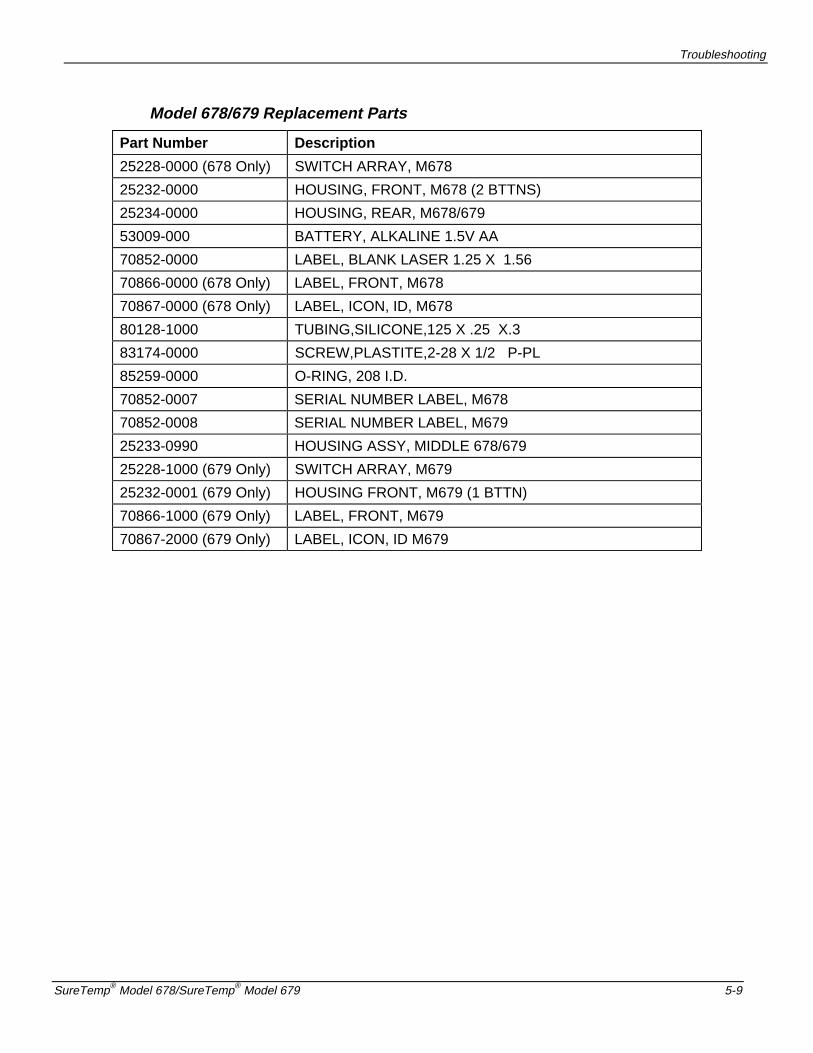
Model 678/679 Replacement Parts
Part Number Description
25228-0000 (678 Only) SWITCH ARRAY, M678
25232-0000 HOUSING, FRONT, M678 (2 BTTNS)
25234-0000 HOUSING, REAR, M678/679
53009-000 BATTERY, ALKALINE 1.5V AA
70852-0000 LABEL, BLANK LASER 1.25 X 1.56
70866-0000 (678 Only) LABEL, FRONT, M678
70867-0000 (678 Only) LABEL, ICON, ID, M678
80128-1000 TUBING,SILICONE,125 X .25 X.3
83174-0000 SCREW,PLASTITE,2-28 X 1/2 P-PL
85259-0000 O-RING, 208 I.D.
70852-0007 SERIAL NUMBER LABEL, M678
70852-0008 SERIAL NUMBER LABEL, M679
25233-0990 HOUSING ASSY, MIDDLE 678/679
25228-1000 (679 Only) SWITCH ARRAY, M679
25232-0001 (679 Only) HOUSING FRONT, M679 (1 BTTN)
70866-1000 (679 Only) LABEL, FRONT, M679
70867-2000 (679 Only) LABEL, ICON, ID M679

Technical Manual
5-10 Welch-Allyn, Inc.
70898-0000A
Replacement Parts-Circuit Board Assemblies
PartNumber
Description Reference Designator
21001-0011 PCA MAIN M678 W/BCKLGHT
46129-1050 CAP 1UF TANTCHIP 16V +/-20% C1
46138-0000 CAP, 10UF, 20%, 16V ALUM C17
46127-1030 CAP 0.01UF 100V X7R CHIP 0805- C19, C2, C20, C22, C5, C6
46136-0000 CAP, .33UF, 10%, 50V TANTB C21
46137-0000 CAP, CHIP, 1UF, 20%, 50V ALUM C25
46140-0000 CAP, CHIP, 22PF, 5%, 50V 0805 C26, C27
46022-000 CAP 0.1UF 50V +80%-20% Z5U - C3, C4
44047-0000 DIODE, DUAL, MMBD1203 D1, D2, D4
43010-0000 INDUCTOR 10UH LOWRES CHIP 1210 L1
50032-0000 TRANS BSS138 FET, SOT-23 Q1, Q2, Q3
50035-0000 TRANSISTOR, PNP W/BIAS RESTOR Q12, Q15
50031-0000 TRANS BCX69 PNP SOT-89 Q13, Q14
50030-0000 TRANS XX5087 PNP SOT-23 Q4, Q5, Q6
50029-0000 TRANS XX2222A NPN SOT-23 Q9
40290-4740 RES, 470K, 5% 0805 SIZE R1
40290-1050 RES 1M, 5% 0805 SIZE R10, R11, R12
40320-0000 RES, 11.55K, 0.05% 25PPM 0805 R13
40290-4720 RES 4.7K SM 5% 0805 SIZE R14, R15, R17, R2
40290-1020 RES 1K, 5% 0805 SIZE R16, R23, R31, R32, R5
40290-1030 RES 10K, 5% 0805 SIZE R21, R30
40290-1630 RES 16K SM 5% 0805 SIZE R28
40290-4730 RES 47K S, 5% 0805 SIZE R3, R4, R6
40290-1500 RES 15, 5% 0805 SIZE R35
40290-1040 RES 100K SM 5% 0805 SIZE R7
40301-2120 RES 12.1K SMO .1% 0805 SIZE R8
54264-3000 IC, UP78PO64 M678/9 REV 2.3 U1
54258-0000 IC, TIMING, TLC555CD U2
54266-0000 IC, 2.4V 2.5% LOW DROPOUT U9
47021-0000 CRYSTAL, SMD, 4.9152 MHZ X1

Troubleshooting
SureTemp® Model 678/SureTemp® Model 679 5-11
Part Number Description Reference Designator
21001-1010 PCA, MAIN, M678 F/C W/BCKLGHT
25229-0000 FRAME, LCD, M678/679
25230-0000(678 Only)
LIGHT PANEL
25231-0000 SPACER, EDAC, M678/679
58536-0000 CONNECTOR, ZEBRA .255X1.82x.10
70869-0000(678 Only)
LABEL, REFLECTIVE, M678
60026-0000(678 Only)
LED, BACKLIGHT, YELLOW D3
58524-0000 CONNECTOR,6 COND,EDGE REC J1
60025-0000 LCD, M678 LCD1
58315-0000 SPEAKER,MINIATURE,PIEZOELECTRIC
LS1
58455-000(678 Only)
SWITCH,REED,10 TO 20 A TURNS S3
58540-0000 SWITCH, PROBE, M678/679 S4
85257-0001(679 Only)
FOAM SPACER 3/16 THK
40290-1500(679 Only)
RES 15, 5% 0805 SIZE R34
Technical Manual
5-12 Welch-Allyn, Inc.
70898-0000A
Thermometer Disassembly
Please note that if your thermometer is within the warranty period, you shouldreturn the unit to an authorized service representative for servicing; failure todo so will invalidate the warranty.
WARNING: This instrument contains microelectronic devices which are highlysusceptible to damage by static discharge. Use proper handlingand grounding techniques while working on the internal electronics.
1. Withdraw the probe from the probe storage well.
2. Unplug the probe connector from the thermometer.
3. Lay the thermometer on its front panel.
4. Remove the Probe Cover Holder /Battery Access Cover from the thermometerback case by firmly pressing on the indentations located on the sides of theBattery Access Cover.
5. Remove the batteries by pulling on the ribbon strap.
6. Remove the four screws from the thermometer back case.
7. Carefully remove the thermometer back case, keeping the thermometerelectronics assembly and mid-frame in the front case.
8. Remove the neck strap or neck strap eyelet.
9. The electronics assembly can be removed from the mid-frame by desoldering thebattery wires from the main PCA, and carefully removing the PCA out of the fronthousing.

Troubleshooting
SureTemp® Model 678/SureTemp® Model 679 5-13
Figure 7 - Thermometer Assembly Drawing
1 Printed Circuit Assy. 7 Battery 3 “AA” 13 O rings (3)
2 Battery Clips (2) 8 Battery Clip Dual 14 Label Front
3 Push Button Switches 9 Label Caution Serial Number 15 Label Icons
4 Front Housing 10 Probe Well 16 Battery Limiter
5 Middle Housing 11 Battery Wires
6. Rear Housing 12 Screws (4)

Technical Manual
5-14 Welch-Allyn, Inc.
70898-0000A
Figure 8 - Main PCA
Notes: Unless otherwise specified:
1. Maximum lead protrusion after trimming to be .060 inch.
2. Square pads indicate pin number 1 of components.
3. Silkscreened circles with no reference numbers are test points.
4. All post-mounting transportation and storage is to be within anti-staticpacking and under anti-electrostatic discharge handling packagingpractices.
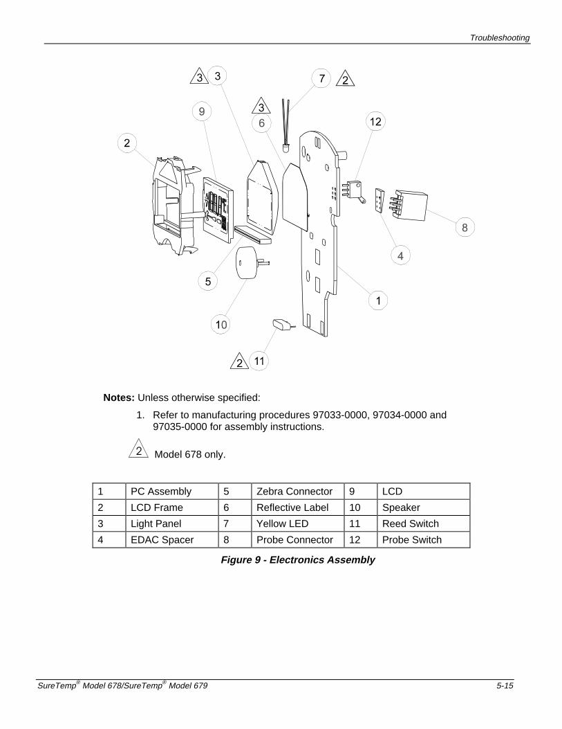
Troubleshooting
SureTemp® Model 678/SureTemp® Model 679 5-15
Notes: Unless otherwise specified:
1. Refer to manufacturing procedures 97033-0000, 97034-0000 and97035-0000 for assembly instructions.
Model 678 only.
1 PC Assembly 5 Zebra Connector 9 LCD
2 LCD Frame 6 Reflective Label 10 Speaker
3 Light Panel 7 Yellow LED 11 Reed Switch
4 EDAC Spacer 8 Probe Connector 12 Probe Switch
Figure 9 - Electronics Assembly

1 2 3 4 5 6 7 8
A
B
C
D
87654321
D
C
B
A
Title
Number RevisionSize
Orcad D
Date: 7-Apr-2000 Sheet of File: I:\Documentation\..\55105C.SCH Drawn By:
CONFIDENTIAL AND PROPRIETARY
PROPERTY OF WELCH ALLYN INC.
1 2
3
1 2 3
4
1 2 3
PROBE OUT = LOPROBE IN = HI
PROBE CONNECTOR
REVISIONS
REV DESCRIPTION DATE
A INITIAL RELEASE
3303EMB713
GND_DIGITAL MUST BE CONNECTED
TO GND_SIGNAL MANUALLY AT LAYOUT.
MAKE CONNECTION NEAR U2-PIN1.
A/D CONVERTER
REFERENCE
PROBE WARMERIrDA CLOCK
IrDA
COMMUNICATIONS
OpticaLTransceiver
ProtocolConverter
DIVIDE BY 4
FET
NOTES:
1
2 2
22
2
2
4
3
POPULATE ON 678 ONLY
S1 SERVES AS MODE ON MODEL 679
POPULATE R35 WHEN IrDA NOT PRESENT
POPULATE R34 ON 679 ONLY
4
POPULATE R37 WHEN IrDA IS PRESENT
MMBT/MUN
A/D_OUT
PROBE_SW
A/D_TRIGGER
PROBE_SEL
PTBCAL_SEL
RCAL_SEL
HTRPWRHTRTST
/HTRC
PTBCAL_SEL
PROBE_SEL
MODEL678/A/D_TRIGGER
SEG0SEG1SEG2SEG3SEG4SEG5SEG6SEG7SEG8SEG9SEG10SEG11SEG12SEG13SEG14SEG15SEG16SEG17
J1-2B
J1-2A
/HTRQ
J1-3B
J1-3A
X2X1
SW
S3
S4
WALL_MOUNT
/RESET
/RESET
PROBE_1
PROBE_0
/HTRQ
/DEGC_ONLY
/MODE
/PTIMER
RCAL_SEL
/PWR_ENABLECOM0COM1COM2
/TXD/RXD
/RXD RD_232
IRDA_VCC
SERSHUTDN
SERSHUTDN
IRDA_CLKIRDA_DISAB
J1-1A
J1-1B
P01
SECURITY_ON
AVREF_DISAB
P13P14
AV
RE
F
P30
P32
P37
S20S19S18
P94
995
P97
S23S22S21
P25
P96
P82
P26P27
XT2
IRDA3_3
IRLED_PWR
TFDPWR
RD_IR
TD_IR
K
IR_A
O73 I73
CK
73
CK37
CK18
RE
FB2
PRBD
PT
BD
CALD
CTRL
TRGOT
BLA
T2
HTRC2
HTB1
HTB2HTE0
HTB0
RD_232
HO
RN
E5
E6
CA
L
SYN
C
P91
/CT
S
/RTS
/BLIGHTCTRL
/IRDA
CLK1_8432M
VCC
VCC
VCC
VCC
VCC
VCC
VCC
VCC
VCC
VREF
VCCVREF
VLC1
VREF
VLC0
BIAS
VCC
VCC
VLC1
VLC0BIAS
VREF
VCC
P R O B E
H E A T E R
T H E R M I S T O R
P R O B E
C
B C E
C U T H E R EF O R R E C T A L
C U T H E R EF O R C A L K E Y
12
R13M
12
R24.7K
12
C20.01UF
12
R347K
12
R447K
1 2R5
1K
123
LS1HORN
21
3D1
MMBD1203
1 2R6
47K
21
3D2MMBD1203
12
C30.1UF
2 1D3
LED
1
32
Q3BSS138
12
R7100K
S21
81S2
282
S23
83P
9.7/
S24
84P
9.6/
S25
85P
9.5/
S26
86P
9.4/
S27
87P
9.3/
S28
88P
9.2/
S29
89P
9.1/
S30
90P
9.0/
S31
91P
8.7/
S32
92P
8.6/
S33
93P
8.5/
S34
94P
8.4/
S35
95P
8.3/
S36
96P
8.2/
S37
97P
8.1/
S38
98P
8.0/
S39
99P
2.5/
SI0
100
P2.6/SO0/SB11
P2.7/SCK02
P7.0/SI2/RXD3
P7.1/SO2/TXD4
P7.2/SCK2/ASCK5
IC(VPP)6
X27
X18
VDD9
XT1/P0.710
XT211
RESET12
P0.0/INTP0/TI0013
P0.1/INTP1/TI0114
P0.2/INTP215
P0.3/INTP316
P0.4/INTP417
P0.5/INTP518
P11.019
P11.120
P11.221
P11.322
P11.423
P11.524
P11.625
P11.726
AVSS27
P1.0/ANI028
P1.1/ANI129
P1.2/ANI230
P1.
3/A
NI3
31
P1.
4/A
NI4
32
P1.
5/A
NI5
33
P1.
6/A
NI6
34
P1.
7/A
NI7
35
AV
DD
36
AV
RE
F37
P10
.038
P10
.139
VSS
40
P10
.241
P10
.342
P3.
0/T
O0
43
P3.
1/T
O1
44
P3.
2/T
O2
45
P3.
3/T
I146
P3.
4/T
I247
P3.
5/P
CL
48
P3.
6/B
UZ
49
P3.
750
COM0 51COM1 52COM2 53COM3 54BIAS 55VLC0 56VLC1 57VLC2 58VSS 59S0 60S1 61S2 62S3 63S4 64S5 65S6 66S7 67S8 68S9 69S10 70S11 71S12 72S13 73S14 74S15 75S16 76S17 77S18 78S19 79S20 80
U1
UPD78062GF
E B C
12
C40.1UF
12
R101M
12
R111M
1 2C5
0.01UF
12
R121M
12
C60.01UF
12
R144.7K1 2
R15
4.7K
1 2R16
1K
12
R174.7K
12
R2110K
R4
V+
8
CTRL5
THR6
TRG2
OUT 3
DSC 7
V-
1
U2
TLC555CD
1 2R23
1K
S09
S110
XIN5
BCLK4
RESET1
RD_UART2
TD_UART3 TD_232 11RD_232 12TD_IR 14RD_IR 15NC 13NC 7NC 6
VC
C16
GN
D8
U3
TOIM3000
A8
K1
TXD7
NC/SNS5
RXD2
SD6
VC
C3
GN
D4
H1
9
H2
10
U4TFDS3000
12
R243.9
12
R2515
12
R26100
12
R274.7K
G1
I2
O 3
N4
U6TC45ER
1 2
C130.1UF
1 2
C140.1UF
12
C150.1UF
12
C160.1UF
1 2R30
10K
1 2
R311K
1 2
R321K
1
23
Q11MUN2111
21
3D4MMBD1203
12
C190.01UF
12
C200.01UF
1 2
C220.01UF
12
C23C0805
12
R34R0805
1 2L1
10UH
1 2 3 4 5 6 7 8 9 10 11 12
J4CON12
12
C240.01UF
1
23
00 U7A
74HC004
56
00 U7B
74HC00
9
108
00
U7C74HC00
CLK11
D12 SD10
CD
13
Q 9
Q 8
U8B74HC74
1 2
R361M
1J5
3 A A
B A T T E R I E S
A L K A L I N E
3 . 0 - 5 . 0 V
1
J6
2
1J2
2
1J3
123456789101112131415161718192021
LCD1
12
+C815UF
12
+C915UF
1
23
Q12MUN2111
CLK3
D2 SD4
CD
1
Q 5
Q 6
G7
V14
U8A74HC74
G2
O3 I 1X27.3728MHZ
1
E64
1
E74
1
E75
1
E76
1
E77
1
E78
1
E79
1
E80
1
E30
1E28
1
E31
1
E81
1
E27
12
C120.1UF
1
E83
1E84
1
E52
1E13
12
C18C0805
1
E51
1 E48
1 E49
1
E7
1
32 Q2
BSS138
1
32 Q1
BSS138
1
E50
1E19
1
E20
1
E15
1
E16
1E87
1
E17
1
E18
1
E67
1
E73
1
E65
1
E66
1
E55
1
E22
1
E24
1
E57
1
E88
1
E33
1
E39
1
E43
1
E47
1E40
1
E42
1
E41
1
E38
1
E37
1
E32
1
E34
1
E35
1 2S2
PB
1 2S1
PB
1
32 4
Q13BCX69
1
32 4
Q14BCX69
1 2+
C21.33UF
1E72
1E70
1E71
1
E6
1E54
1
E5
1
E4
1E2
1E3
1
E8
1E9
1E59
1E60
1 E82
1E56
1E29
1
E26
1
E63
1
E62
1
E89
1
E90
1E91
1
32
Q9XX2222
1
23
Q5
XX5087
1
23
Q6XX5087
1
23
Q4XX5087
12
S3SW_REED
23
1
S4SW_SPDT
1 E36
1
E61
1
E68
1E58
12
+ C251UF
12
R812.1K
0.1% 100PPM 1/8W
12
R1311.55K
0.05% 25PPM RN55
12
+C1710UF
12
+ C1110UF
1 2+
C1010UF
1 2
R35RES 0805
CD
BG
ES
12
R37100
12 +
C1
1.0UF
1
E92
1
23
Q15MUN2111
G1
I2
O 3
N4
U9TC45ER
12
R28
16K
1
E45
/HOST_WAKEUP
B
B
B
A
A
A
1
2
3
1
2
3 WELCH ALLYNTHIS INFORMATION IS THE
PROPERTY OF WELCH ALLYN
FILE:
APPROVAL
CHECK
PROJ. MGR.
Q.A.
MFG. ENG.
REL. AUTH.
DATE
E Rivera1 OF 1
AND IS NOT TO BE DISCLOSEDOR UTILIZED WITHOUT WRITTEN
IT IS SUBMITTED IN CONFIDENCE
PERMISSION
SCHEMATIC, 678/679 PCB
55105-0000 C
ECO
2835 11/7/96
12
1311
714
U?D
00
BREPLACED x1 RESONATOR WITH CRYSTALADDED CAPACITORS C26 AND C27REMOVED P11.4 FROM GROUNDCONNECTED P11.4 TO P11.5
2835-10 1/30/97
MOVED ONE SIDE OF R1 FROM Q5 EMITTER TO VCCCHANGED VALUE OF R1 FROM 470K TO 3M
6/10/983192C
12
C2722 pF
12
C2622 pF
X1
4.9152MHz
3
2
1
4
4

Technical Manual
5-16 Welch-Allyn, Inc.
70898-0000A