6.11s notes for lecture 4 analysis of induction machines june 15, 2006 j.l. kirtley jr
DESCRIPTION
6.11s Notes for Lecture 4 Analysis of Induction Machines June 15, 2006 J.L. Kirtley Jr. Induction motor stator and rotor windings are coupled together much like windings of a transformer. But the coupling is dependent on rotor position:. Rotor angle. Stator Rotor. - PowerPoint PPT PresentationTRANSCRIPT
1 6.11s June 2006 L4 1
6.11s Notes for Lecture 4Analysis of Induction Machines
June 15, 2006J.L. Kirtley Jr.
2 6.11s June 2006 L4 2

3 6.11s June 2006 L4 3
4 6.11s June 2006 L4 4
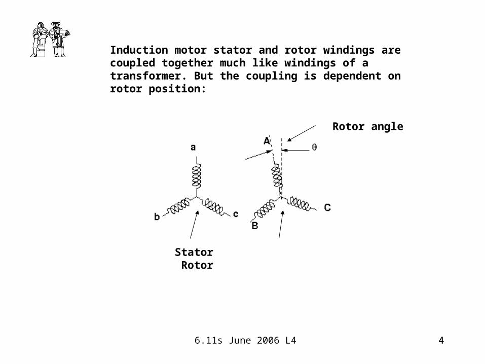
Induction motor stator and rotor windings are coupled together much like windings of a transformer. But the coupling is dependent on rotor position:
Stator Rotor
Rotor angle
5 6.11s June 2006 L4 5
6 6.11s June 2006 L4 6
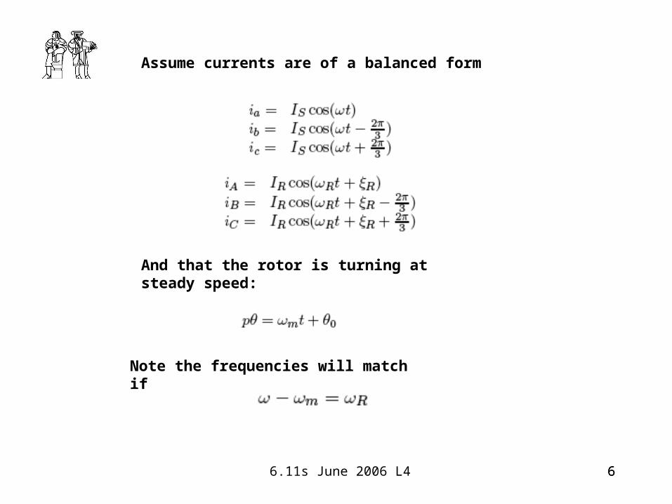
Assume currents are of a balanced form
And that the rotor is turning at steady speed:
Note the frequencies will match if
7 6.11s June 2006 L4 7
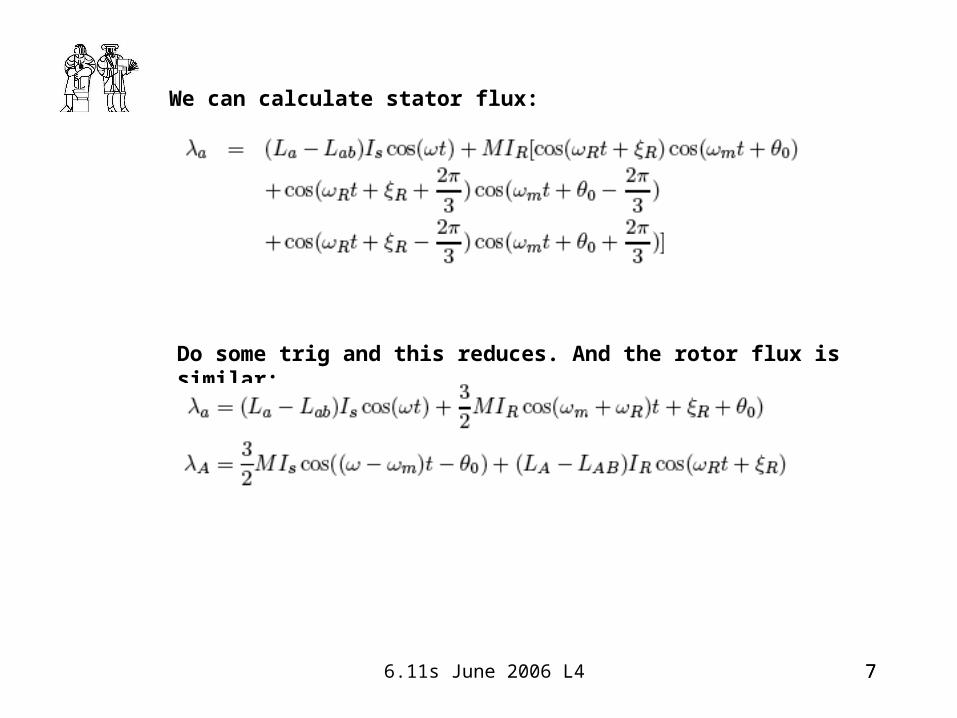
We can calculate stator flux:
Do some trig and this reduces. And the rotor flux is similar:
8 6.11s June 2006 L4 8
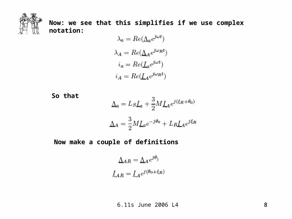
Now: we see that this simplifies if we use complex notation:
So that
Now make a couple of definitions
9 6.11s June 2006 L4 9
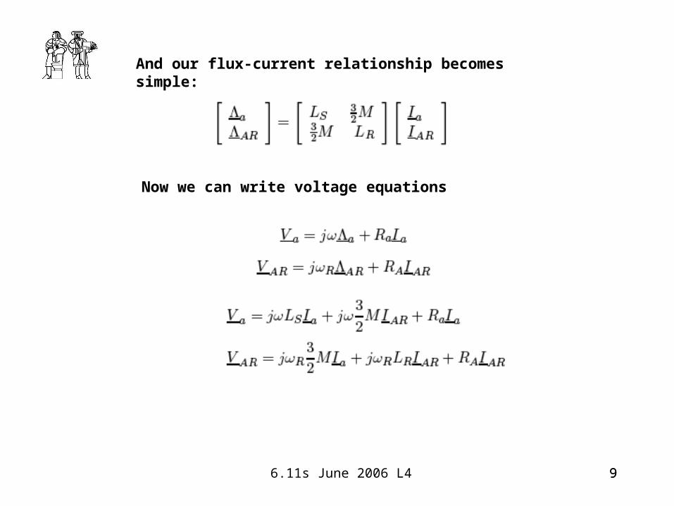
And our flux-current relationship becomes simple:
Now we can write voltage equations
10 6.11s June 2006 L4 10
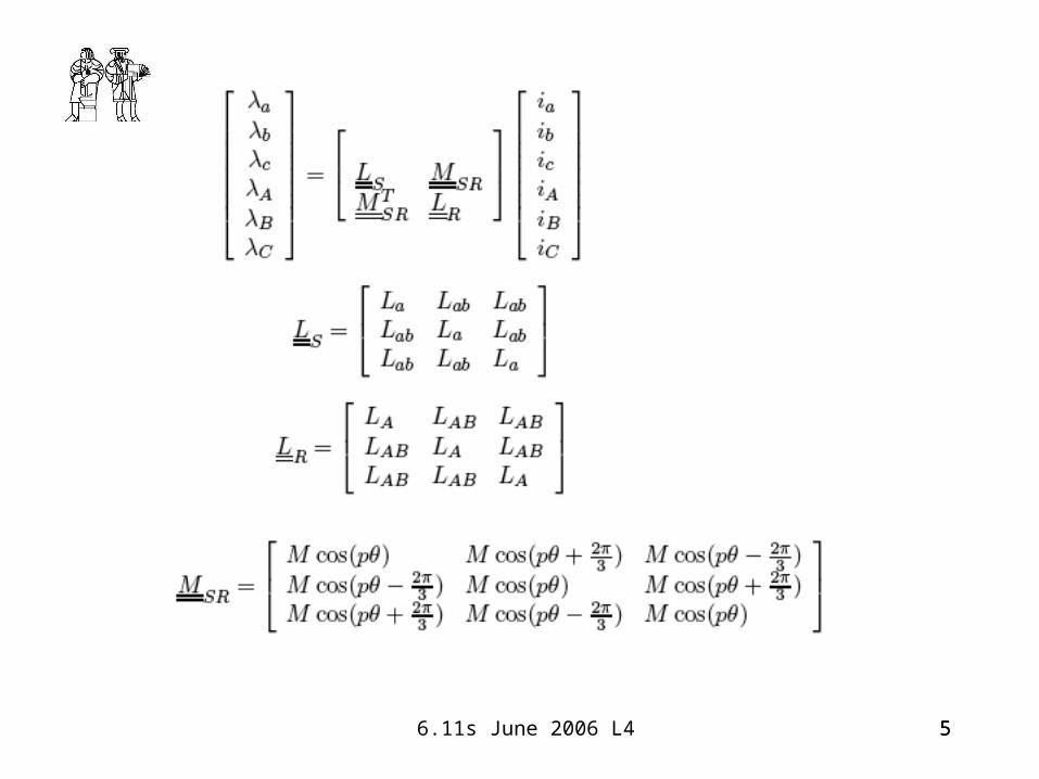
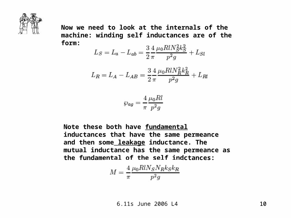
Now we need to look at the internals of the machine: winding self inductances are of the form:
Note these both have fundamental inductances that have the same permeance and then some leakage inductance. The mutual inductance has the same permeance as the fundamental of the self indctances:

11 6.11s June 2006 L4 11
Those inductances can be written as:
Slip is defined by:
We can re-write the voltage equations:
12 6.11s June 2006 L4 12
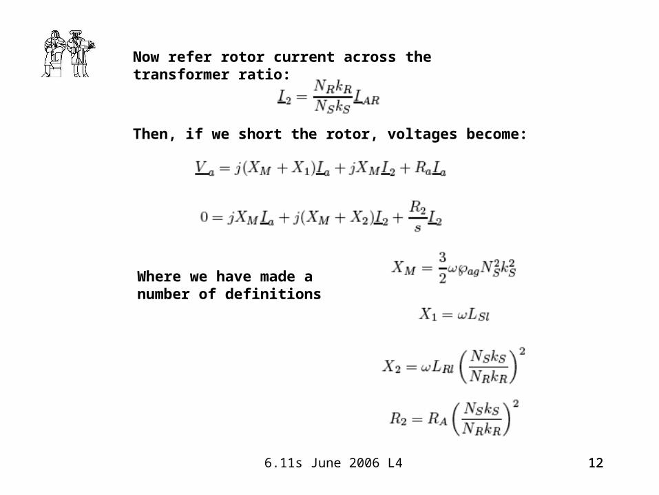
Now refer rotor current across the transformer ratio:
Then, if we short the rotor, voltages become:
Where we have made a number of definitions
13 6.11s June 2006 L4 13
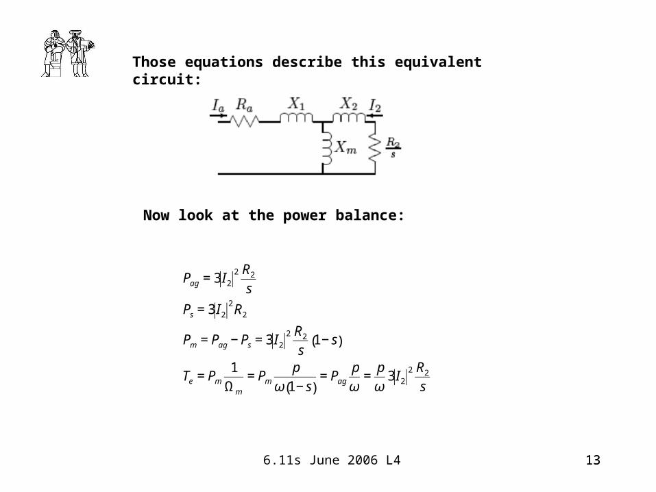
Those equations describe this equivalent circuit:
Now look at the power balance:
€
Pag = 3 I22 R2
s
Ps = 3 I22R2
Pm = Pag − Ps = 3 I22 R2
s1− s( )
Te = Pm1
Ωm
= Pmp
ω 1− s( )= Pag
p
ω=p
ω3 I2
2 R2
s

14 6.11s June 2006 L4 14

15 6.11s June 2006 L4 15
Squirrel Cage Motor Model:
We want to work with a rotor surface current:
This current makes a magnetic flux density in the gap:
And that produces a flux (in the stator) of:
16 6.11s June 2006 L4 16
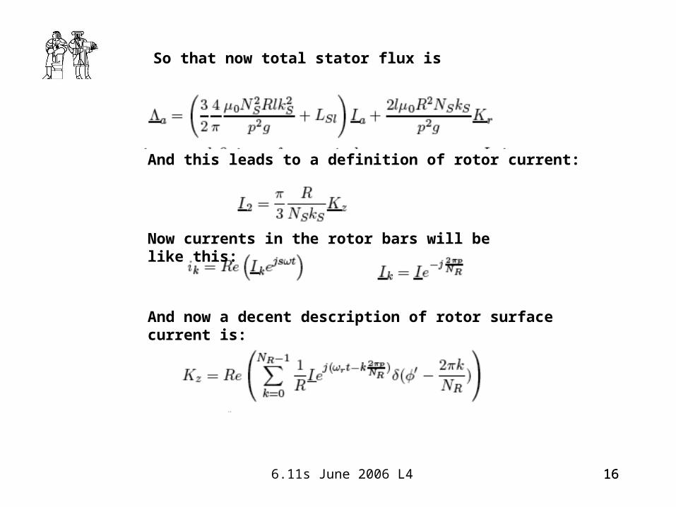
So that now total stator flux is
And this leads to a definition of rotor current:
Now currents in the rotor bars will be like this:
And now a decent description of rotor surface current is:
17 6.11s June 2006 L4 17
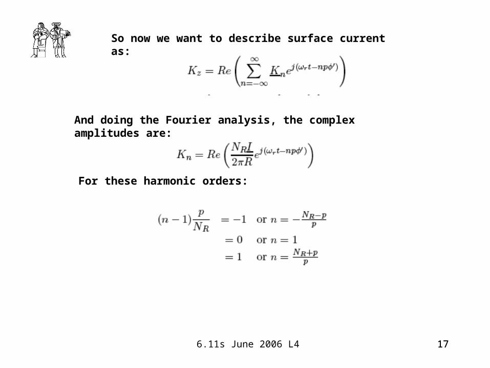
So now we want to describe surface current as:
And doing the Fourier analysis, the complex amplitudes are:
For these harmonic orders:
18 6.11s June 2006 L4 18
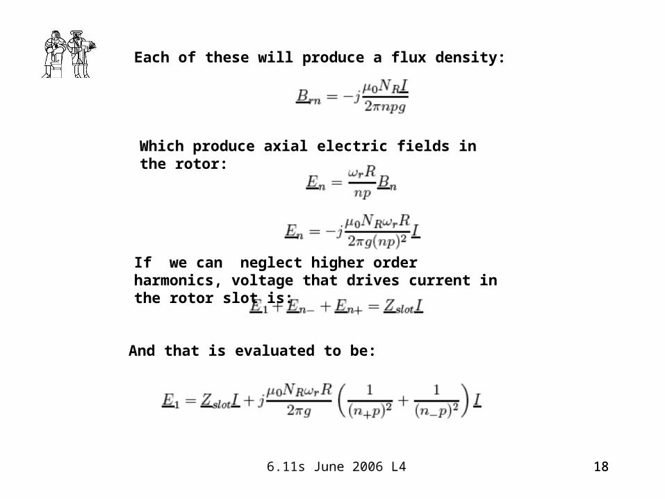
Each of these will produce a flux density:
Which produce axial electric fields in the rotor:
If we can neglect higher order harmonics, voltage that drives current in the rotor slot is:
And that is evaluated to be:
19 6.11s June 2006 L4 19
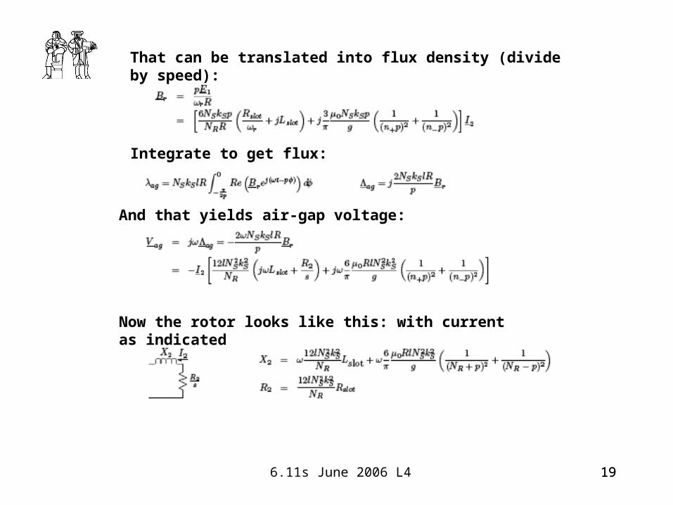
That can be translated into flux density (divide by speed):
Integrate to get flux:
And that yields air-gap voltage:
Now the rotor looks like this: with current as indicated
20 6.11s June 2006 L4 20
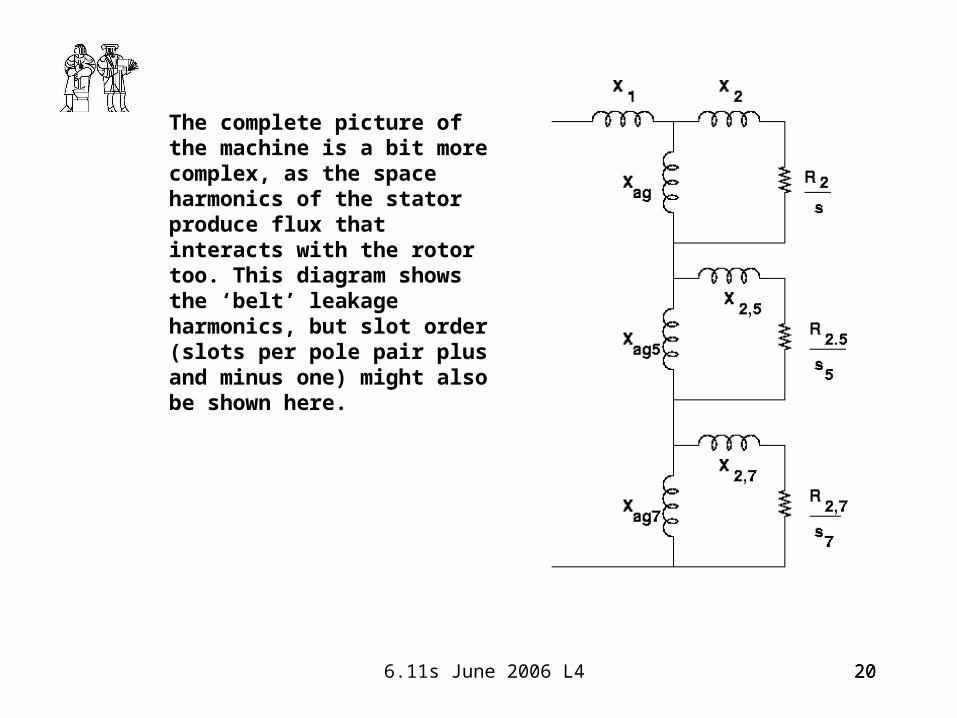
The complete picture of the machine is a bit more complex, as the space harmonics of the stator produce flux that interacts with the rotor too. This diagram shows the ‘belt’ leakage harmonics, but slot order (slots per pole pair plus and minus one) might also be shown here.
21 6.11s June 2006 L4 21
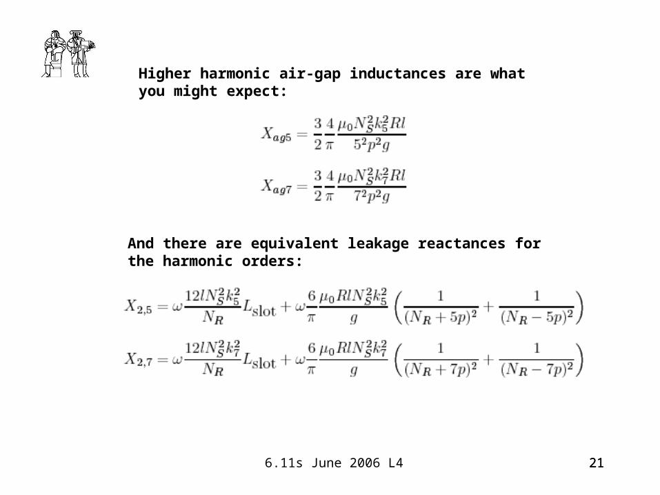
Higher harmonic air-gap inductances are what you might expect:
And there are equivalent leakage reactances for the harmonic orders:
22 6.11s June 2006 L4 22
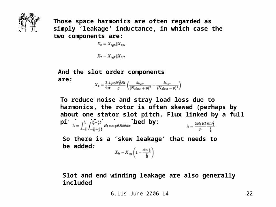
Those space harmonics are often regarded as simply ‘leakage’ inductance, in which case the two components are:
And the slot order components are:
To reduce noise and stray load loss due to harmonics, the rotor is often skewed (perhaps by about one stator slot pitch. Flux linked by a full pitch coil is described by:
So there is a ‘skew leakage’ that needs to be added:
Slot and end winding leakage are also generally included
23 6.11s June 2006 L4 23
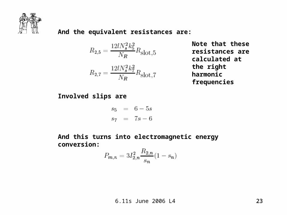
And the equivalent resistances are:
Involved slips are
And this turns into electromagnetic energy conversion:
Note that these resistances are calculated at the right harmonic frequencies
24 6.11s June 2006 L4 24
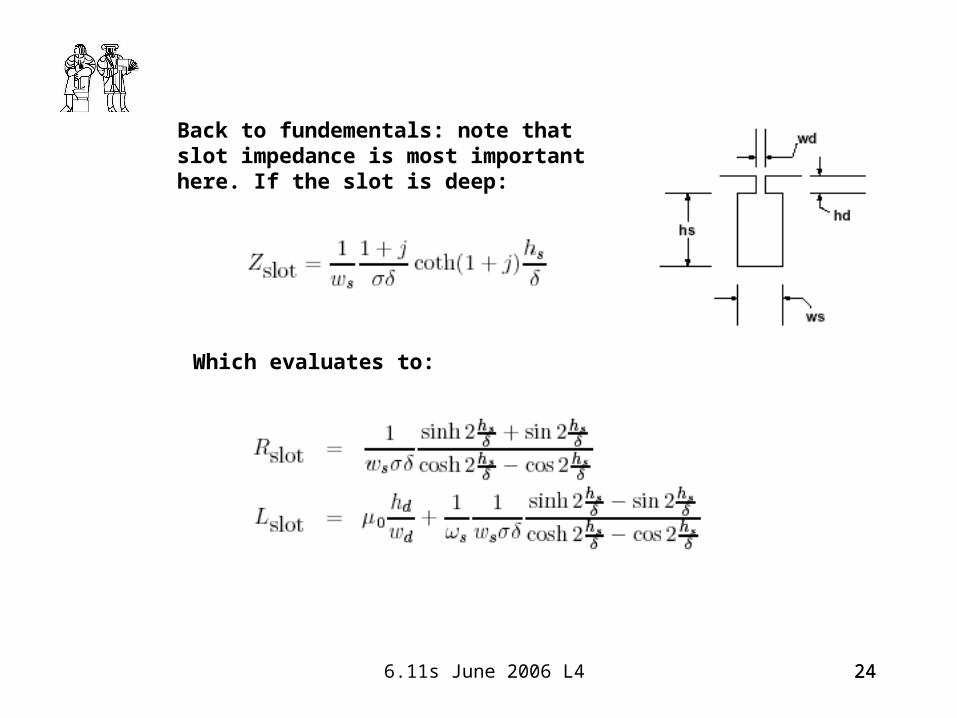
Back to fundementals: note that slot impedance is most important here. If the slot is deep:
Which evaluates to:
25 6.11s June 2006 L4 25
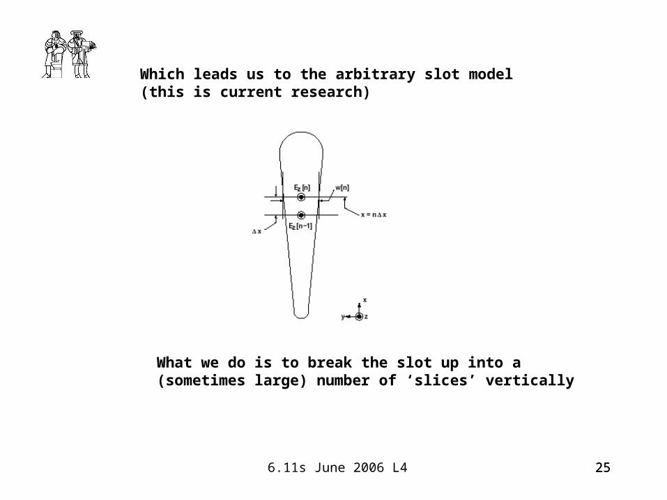
Which leads us to the arbitrary slot model (this is current research)
What we do is to break the slot up into a (sometimes large) number of ‘slices’ vertically
26 6.11s June 2006 L4 26
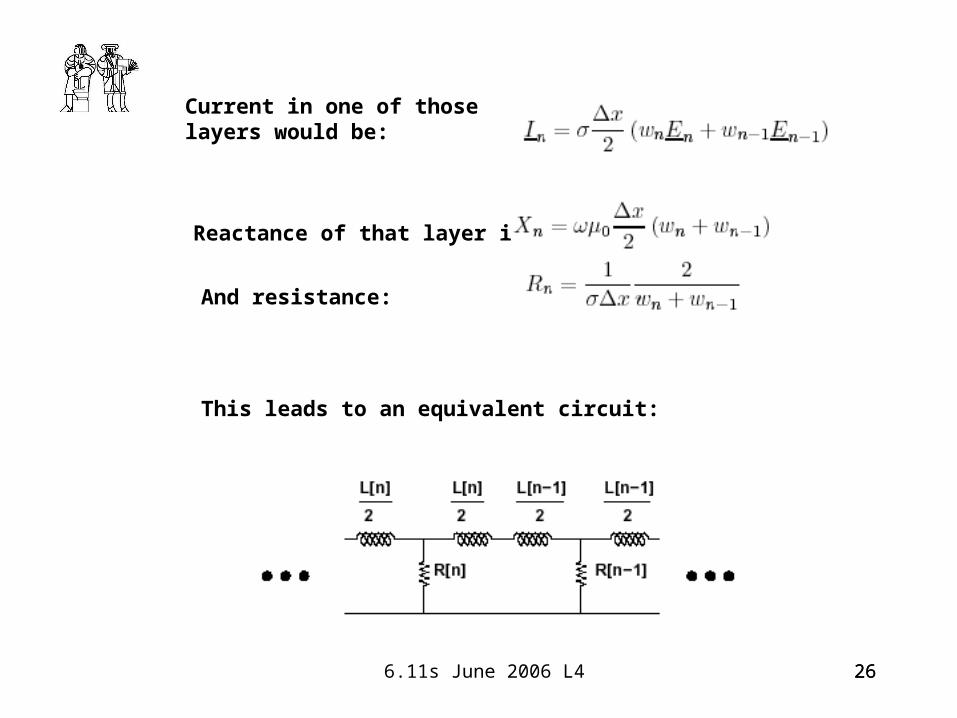
Current in one of those layers would be:
Reactance of that layer is:
And resistance:
This leads to an equivalent circuit:
27 6.11s June 2006 L4 27
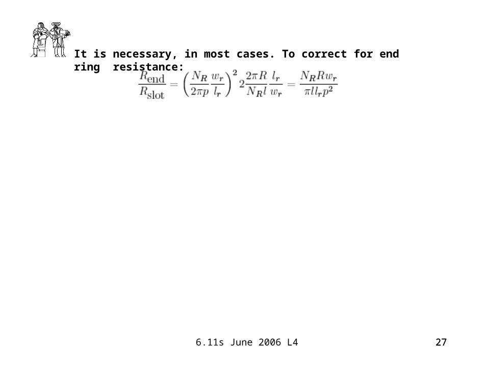
It is necessary, in most cases. To correct for end ring resistance:
28 6.11s June 2006 L4 28
29 6.11s June 2006 L4 29
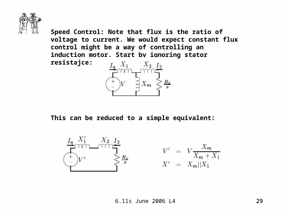
Speed Control: Note that flux is the ratio of voltage to current. We would expect constant flux control might be a way of controlling an induction motor. Start by ignoring stator resistajce:
This can be reduced to a simple equivalent:

30 6.11s June 2006 L4 30
Current and torque are found (quite simply) to be:
Defining slip and voltage with respect to base quantities:
We find torque with respect to an absolute slip:
31 6.11s June 2006 L4 31
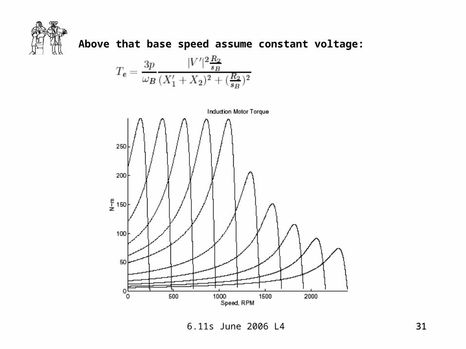
Above that base speed assume constant voltage:

32 6.11s June 2006 L4 32
With a more realistic motor model:
33 6.11s June 2006 L4 33
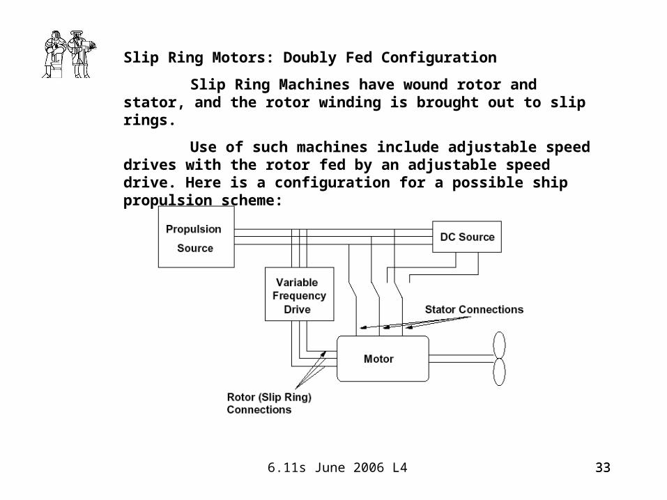
Slip Ring Motors: Doubly Fed Configuration
Slip Ring Machines have wound rotor and stator, and the rotor winding is brought out to slip rings.
Use of such machines include adjustable speed drives with the rotor fed by an adjustable speed drive. Here is a configuration for a possible ship propulsion scheme:
34 6.11s June 2006 L4 34
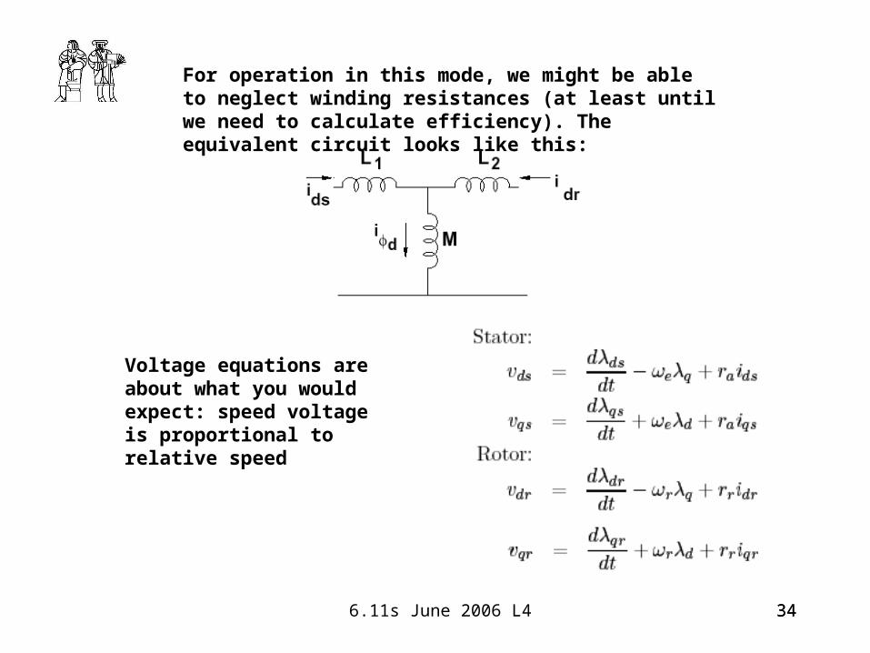
For operation in this mode, we might be able to neglect winding resistances (at least until we need to calculate efficiency). The equivalent circuit looks like this:
Voltage equations are about what you would expect: speed voltage is proportional to relative speed
35 6.11s June 2006 L4 35
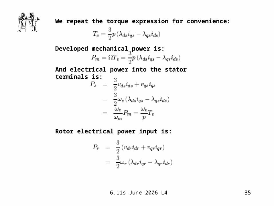
We repeat the torque expression for convenience:
Developed mechanical power is:
And electrical power into the stator terminals is:
Rotor electrical power input is:

36 6.11s June 2006 L4 36
Current/Flux relationships are:
Then rotor and stator innput power are:
And they are rerlated by:
37 6.11s June 2006 L4 37
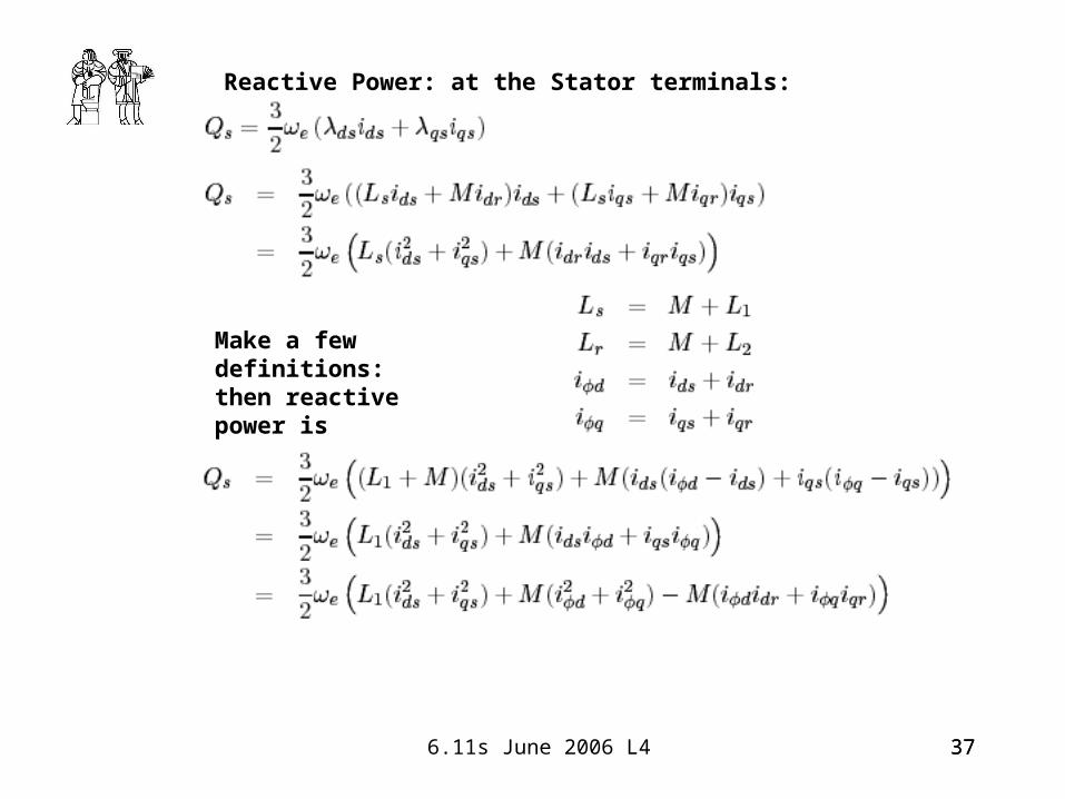
Reactive Power: at the Stator terminals:
Make a few definitions: then reactive power is
38 6.11s June 2006 L4 38
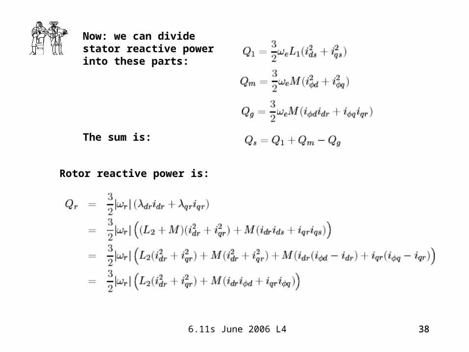
Now: we can divide stator reactive power into these parts:
The sum is:
Rotor reactive power is:
39 6.11s June 2006 L4 39
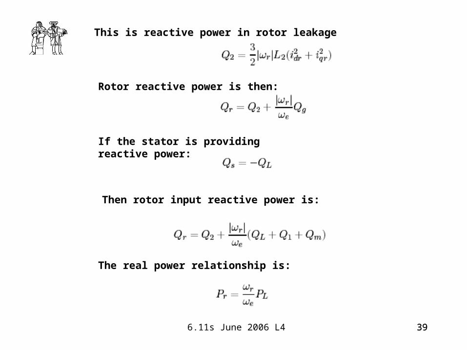
This is reactive power in rotor leakage
Rotor reactive power is then:
If the stator is providing reactive power:
Then rotor input reactive power is:
The real power relationship is:

40 6.11s June 2006 L4 40