6. srm - stratospheric aerosol
TRANSCRIPT
Lecture „Climate Engineering“
6. SRM - Stratospheric Aerosol
Ulrich Platt
Institut für Umweltphysik

Lecture Program of „Climate Engineering
2
Part 1: Introduction to the Climate System (4 sessions)1. Introduction and scope of the lecture2. The Climate System – Radiation Balance 3. Elements of the Climate System - Greenhouse Gases, Clouds, Aerosol4. Dynamics of the Climate System - Sensitivity, PredictionsPart 2: Climate Engineering Methods - Solar Radiation Management, SRM1. SRM – Reflectors in space 2. SRM – Aerosol in the Stratosphere3. SRM – Cloud Whitening4. SRM – Anything elsePart 3: Climate Engineering Methods – Carbon Dioxide Removal, CDR1. Direct CO2 removal from air2. Alkalinity to the ocean (enhanced weathering)3. Ocean fertilization4. Removal of other greenhouse gasesPart 4: CE – Effectiveness, Side Effects (3 sessions) 1. Comparison of Techniques, characterisation of side effects2. Other parameters than temperature3. Summary

Literature - 1
Crutzen P. (2006), Albedo Enhancement by Stratospheric Sulfur Injections: A Contribution to Resolve a Policy Dilemma? An Editorial Essay, Clim. Change, doi:10.1007/s10584-006-9101-y.
English J.M., Toon O.B., and Mills M.J. (2012), Microphysical simulations of sulfur burdens from stratospheric sulfur geoengineering, Atmos. Chem. Phys., 12, 4775–4793.
Heckendorn P., Weisenstein D., Fueglistaler S., Luo B.P., Rozanov E ., Schraner M., ThomasonL.W. and Peter T. (2009), The impact of geoengineering aerosols on stratospheric temperatureand ozone, Environ. Res. Lett. 4, 045108, doi:10.1088/1748-9326/4/4/045108.
Kleinschmitt C., Boucher O., and Platt U. (2018), Sensitivity of the radiative forcing by stratospheric sulfur geoengineering to the amount and strategy of the SO2 injection studied with the LMDZ-S3A model, Atmos. Chem. Phys. 18, 2769–2786.
Kremser, S., Thomason, L.W., von Hobe, M., Hermann, M., Deshler, T., Timmreck, C., Toohey, M., Stenke, A., Schwarz, J. P.,Weigel, R., Fueglistaler, S., Prata, F. J., Vernier, J.-P., Schlager, H., Barnes, J. E., Antuña-Marrero, J.-C., Fairlie, D., Palm, M., Mahieu, E., Notholt, J., Rex, M., Bingen, C., Vanhellemont, F., Bourassa, A., Plane, J. M. C., Klocke, D., Carn, S. A., Clarisse, L., Trickl, T., Neely, R., James, A. D., Rieger, L., Wilson, J. C., and Meland, B. (2016), Stratospheric aerosol—Observations, processes, and impact on climate, Reviews of Geophysics, 54, 278–335, doi:10.1002/2015RG000511.
Laakso A., Partanen A.-I., Kokkola H., Laaksonen A., Lehtinen K.E.J. and Korhonen H. (2012), Stratospheric passenger flights are likely an inefficient geoengineering strategy, Environ. Res. Lett. 7, 034021 (7pp), doi:10.1088/1748-9326/7/3/034021.

Literature - 2
McClellan J., Sisco J., Suarez B., Keogh G. (2011), Geoengineering Cost Analysis, Final Report AR10-182, Aurora Flight Sciences Corp., Cambridge, Mass. 02142.
Niemeier U., Schmidt H., and Timmreck C. (2011), The dependency of geoengineeredsulfate aerosol on the emission strategy, Atmos. Sci. Lett., 12, 189–194, doi:10.1002/asl.304,
Pierce J.R., Weisenstein D.K., Heckendorn P., Peter T., and Keith D.W. (2010), Efficient formation of stratospheric aerosol for climate engineering by emission of condensiblevapor from aircraft, Geophys. Res. Lett. 37, L18805, doi: 10.1029/2010GL043975.
Rasch P.J., Tilmes, J., Turco R. P., Robock A., Oman l., Chen C.C., Stenchikov G. l., Garcia, R. (2008), An overview of geoengineering of climate using stratospheric sulphate aerosols, Philosophical transactions of the Royal Society A, 4007 – 4037.
Tuck A.F., Donaldson D.J., Hitchman M.H., Richard E.C., Tervahattu H., Vaida V., Wilson J. C. (2008), On geoengineering with sulphate aerosols in the tropical uppertroposphere and lower stratosphere, Climatic Change 90, 315 – 331.
Contents of Today's Lecture
• Stratospheric Particle injection – Inspired by volcanoes
• Stratospheric Sulfur Aerosol – optimum particle size
• Scalability of sulfur injections
• Side effects of stratospheric particles
• „Improved aerosol“
• Delivery techniques
• Effect on climate
• Conclusion

Keith, David, 2001: Geoengineering, Nature, 409, 420. 6

Stratospheric Particle Injection – Inspired by VolcanicEruptions
Crutzen P. (2006), Albedo Enhancement byStratospheric Sulfur Injections: A Ccontribution to Resolve a Policy Dilemma? An Editorial Essay, Climatic Change (2006),
Policy Dilemma: CO2-emission (heatingEarth) comes with SO2-Aerosol (coolingEarth)

Explosive
NET COOLING
Stratospheric aerosols
(Lifetime 1-3 years)
Ash
Effectson cirrusclouds
absorption (IR)
IR
Heating
emission
emission
IR Cooling
More
Downward
IR Flux
Less
Upward
IR Flux
forward scatter
Enhanced
Diffuse
FluxReduced
Direct
Flux
Less TotalSolar Flux
Heterogeneous LessO3 depletion Solar Heating
H2S
SO2
NET HEATING
Tropospheric aerosols
(Lifetime 1-3 weeks)
Quiescent SO2 H2SO4
H2SO4
CO2
H2O
backscatter
absorption
(near IR)Solar Heating
More Reflected
Solar Flux
Indirect Effects on
Clouds
Stratospheric Sulfate Aerosol
from a presentation by Alan Robock, Heidelberg 2010 8

Mount Pinatubo (1)Eruption June 1991
before
after
Photo: NASA

Mount Pinatubo (2)
A) Optically thick layers of stratospheric aerosol, taken from space shuttle Atlantis on 11 Aug. 1991. Foto: Earth Sciences & Image Analysis Laboratory, NASA, Johnson Space Center. B) Continental discharge averaged over the annual water year (October through September values); 1 Sv = 106 m3/s. From: K.E. Trenberth, A. Dai, Geophys. Res. Lett. 34, L15702, (2007).
Hegerl G.C. and Solomon S. (2009), Risks of Climate Engineering, SCIENCE 325, 955-956.
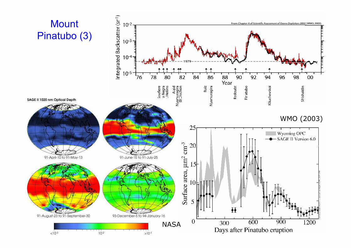
WMO (2003)
NASA
Mount Pinatubo (3)

Effects of Mount Pinatubo, Philipines volcanic eruption (June 1991) on the radiation balance and on the hydrological cycle as an analog of geoengineering
Trenberth and Dai (2007)Geophys. Res. Lett.
from a presentation by Alan Robock, Heidelberg 2010
Mount Pinatubo (4)
12
Reflection
Surface

1783-84, Lakagígar (Laki), Iceland
13

from a presentation by Alan Robock, Heidelberg 2010 14
oC

from a presentation by Alan Robock, Heidelberg 2010 15%

Effectiveness of Particles in the Stratosphere
Parameter Property Dependance on radius (r)
Scattering of radiation Cross-sectional area
Albedo (of the particle)(also: „colour“)
Mass (instantaneously requiredin the stratosphere)
Volume, Density
Lifetime(determines amount of mass to be deposited in the strat. annually)
Settling velocity
Coagulation
Chemical Effectivity Surface area
2r
r
wavelength
3r
2r (or r)
32Mass r
2r

Aerosol Physics: Settling Velocity
Why don't aerosol particles simply drop to the ground?
Settling velocity v of a spherical particle (mass m) in a viscous fluid (e.g. air):
a) Acceleration by gravitational force minus buoyancy:
3 3
G p f p
4 4F mg b r g r g
3 3
2
p
2 grv
9
p: Density of the particlef: Density of the fluid
b) Deceleration by frictional (drag) force: Stokes' law
SF 6 rv : dynamic viscosity of the fluidr: radius of the particle
Stokes' law is valid for laminar flow up to Re 0.1
Settling (or terminal) velocity from FG = FS:
Note: v r2
E.g. for particle with r = 1 m, = 103 kg/m3 in air: v 10-4 m/s or 10 m/d
17

Stratosphere: Do Particles Settle Faster in ThinAir?
2
p
2 grv
9
Settling velocity:
Dynamic viscosity:�
air air air moleckinematic viscosity
1v
3
air
air Avogadro
1 M
2n 2 N
Mean free path:M = Molar Mass
(kg/mole) ofair
= collision crosssection of airmolecules
�
�������
air molec molec
Avogadroair Avogadro T
constant
1 M 1 Mv v
3 N2 N 3 2
Dynamic viscosity is independent of pressure! settling velocity(of large particles) essentially independent of altitude (only T-effect)

Small Particles: Molecular Flow
Knudsen Number:
Very small particles: Is continuum mechanics O.K.?
air
p
g r2 1v , r
9 p
For Kn > 1 (air > r) we are in the regime of molecular flow.Stokes' law for the frictional force must be modified.
2r 0
S A 1air
1 rF 6 rv 6 v
1 A KnStokes-Cunningham formula
Settling velocity for large Kn (small particles, low pressure):
Note: v r (not r2)
For air: Remember
Thus for particle with r =1 m: Kn ≈ 0.06 << 1 (1 atm), Kn ≈ 2.4 at 25 mbar
airmean free path
Knparticle radius r
For Kn << 1 the fluid can be described as a continuum, i.e. by macroscopic quantities such as viscosity and density.
1
air 2n 0.06 m at 1 atm, 2.4 m at 25mbar
Small particles do settle faster in the stratosphere!

Aerosol Physics: Aerosol – RadiationInteraction
Rayleigh scattering: scattering on air moleculesradius of scatterers r << λSW radiation (λ ≈ 100s of nm) and
gas molecules (r ≈ 0.1 nm)
Mie scattering: Scattering on particles, aerosols, dropletsradius of scatterers r ≥ λSW radiation and aerosol particles
or droplets (100 nm < r < 50 μm)
Size parameter x to compareparticle size and wavelength of light:
x << 1 for molecules and fine particles: Rayleigh Scattering
x 1 for coarse particles and clouds: Mie Scattering
2 rx
20

Scattering
Phase Functio
ns
x = 10
x = 3
x = 1
Size Parameter:
2 rx
21From: Thesis Sanghavi
Problem: Scattering mostlyforward, in particular forlarge particles
Particles must be small!
For =0.6 m
r 0.1 m
For =0.6 m
r 0.3 m
For =0.6 m
r 1 m

MorePhase Functions
= 0.6m x = 0.314
x = 1
x = 3.14
x = 0.63
x = 1.2
x = 5
r=0.06m

Scattering Efficiency as a Function of Particle Size
Scattering coefficient or efficiency comparesscattering cross-section to geometrical cross-section:
scatscat 2
Qr
Particles must be big!
0.01 0.1 1 10
10-7
10-6
10-5
10-4
10-3
10-2
10-1
100
101
Sca
tte
rin
ge
ff. Q
sca
t
pol. parallel
pol. perpend.
Size parameter x
Rayleigh regime
Mie regime
2 rx

Optimal Particle Size?
Small Particles More Surface/Mass (less mass needed)
But at size parameter x < 1 rapidlydecreasing scattering efficiency
But more scattering in backward direction
also: particles settle less rapidly
However, the useful lifetime of particles is also limitedby the stratospheric circulation
1 large particle, 8 small particles, radius r/2, same total volumeradius r but twice the total surface area

Aerosol Backscatter Fraction as a Function of SizeParameter
�
cos
1
0
BackscatterFractionBF :
scatteringangle
d
BFforomnidirectionalillumination
=0o
=60o
Wiscombe W. and Grams G. (1976), The back-scattered fraction in two-stream approximations, J. Atmos. Sci. 33, 2440–2451.

Scattering of Short-Wave Radiation =0.6 m
Aerosol Layer Tiny particler 0.1 m
small particler 0.3 m
Large particler 1 m
Mie Scattering Diagrams
Surface

Optimal Particle Size
Dependence of parameters of the radiative forcing of stratospheric aerosol on radius
Blue: SW-cooling effect relative to the particle mass in the stratosphere
Red: Settling velocity of the particles (calculated for 25 km altitude).
Pierce et al. Geophys. Res. Lett. 37, L18805, doi:10.1029/2010GL043975, 2010
Optimum radius

Problems of Stratospheric Aerosol SRM
Pierce et al. Geophys. Res. Lett. 37, L18805, doi:10.1029/2010GL043975, 2010
Particles toosmall to scatterlight at all
Small Particlescoagulatequickly
Large Particlesmostly scatter in forward direction
Large Particlessettle quickly
Large Particles: little surface/mass

Stratospheric Aerosol Life Cycle
From:
Kremser et al., 2016

Which Particle Size-Distribution will Result?
Processes:
1) SO2 H2SO4 conversion
2) Nucleation (new particle formation)
3) Condensation (growth of existing particles)
4) Coagulation
5) Sedimentation

SW Scattering vs. LW scattering
Optimum particleradius r=0.2m
Size parameter forvisible (SW) radiation:
SW
scatt
2 rx
2 0.2 m2.1
0.6 m
Q 0.8
Size parameter forthermal IR (LW) radiation:
LW
scatt
2 0.2 mx 0.10
12 m
Q 0.007
0.01 0.1 1 10
10-7
10-6
10-5
10-4
10-3
10-2
10-1
100
101
Sca
tte
rin
ge
ff. Q
sca
t
pol. parallel
pol. perpend.
Size parameter x
Rayleigh regime
Mie regime
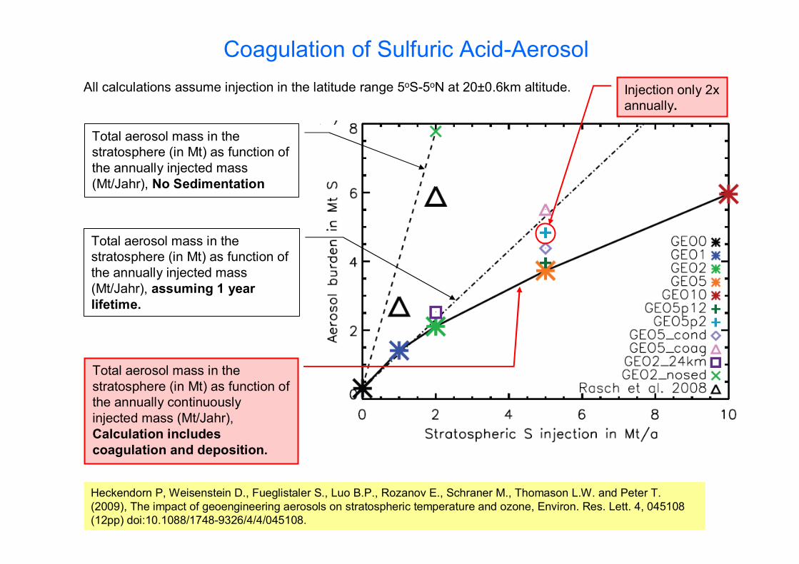
Coagulation of Sulfuric Acid-Aerosol
Heckendorn P, Weisenstein D., Fueglistaler S., Luo B.P., Rozanov E., Schraner M., Thomason L.W. and Peter T. (2009), The impact of geoengineering aerosols on stratospheric temperature and ozone, Environ. Res. Lett. 4, 045108 (12pp) doi:10.1088/1748-9326/4/4/045108.
All calculations assume injection in the latitude range 5oS-5oN at 20±0.6km altitude.
Total aerosol mass in thestratosphere (in Mt) as function of the annually continuouslyinjected mass (Mt/Jahr), Calculation includes
coagulation and deposition.
Total aerosol mass in thestratosphere (in Mt) as function of the annually injected mass(Mt/Jahr), assuming 1 year
lifetime.
Total aerosol mass in thestratosphere (in Mt) as function of the annually injected mass(Mt/Jahr), No Sedimentation
Injection only 2x annually.

Cooling Effekt of Sulfur Injetions into the Stratosphere
Calculations of Heckendorn et al. 2009:Reduction of the global net Insolation (net SW-Flx) as function of the mass of sulfur(in Mt/year) annually injected into the stratosphere.
At large amounts of S the cooling effect increases only marginally!
Extrapolation from Volcanic events too optimistic!
Injection only2x annually.
Calculations fromRobock et al. 2008
ContinuousS-Injection

Solution of the Coagulation Problem – by direct Injection of Sulfuric Acid into the Stratosphere?
Pierce et al. Geophys. Res. Lett. 37, L18805, doi:10.1029/2010GL043975, 2010
Injection of H2SO4 -aerosol instead of SO2
Optimum particle radius
Aerosol size distribution for direct H2SO4
– injection into the stratosphereReduction of the radiative forcing as function of annual mass of sulfur injected
However, see:Niemeier et al. 2011English et al. 2012

StratosphericAerosol(annual
average)Solid coloured lines:Geoengineering (5 MT S/a), emissions spread between 30°S and 30°N and 20 and 25 km.
Dashed magenta lines: Geoengineering (5 MTS/a) as SO2 at a single grid point centered at the equator and 20 km [from Heckendornet al., 2009].
Dashed orange lines: AER model simulation for January–February 1992 following the Mt. Pinatubo eruption.
Dashed black line: size distribution fit to measurements by optical particle counter at 41°N in Jan. 1992
Aerosol number distr., Equator, 23 km altitude
Aerosol mass distr., Equator, 23 km altitude
Aerosol number distr., 40oN, 17 km altitude (AER model)
Pierce et al. Geophys. Res. Lett. 37, L18805, 2010,doi:10.1029/2010GL043975

SRM-2: Our Model Calculations: For equatorial SO2
injections -2.0 W/m2 could not be exceeded.
Kleinschmitt C., Boucher O., Bekki S., Lott F., and Platt U. (2017), The Sectional Stratospheric Sulfate Aerosol module S3A-v1 within the LMDZ general circulation model: Description and evaluation against stratospheric aerosol observations, Geosci. Model Dev. 10, 3359–3378.
Kleinschmitt C., Boucher O., and Platt U. (2018), Sensitivity of the radiative forcing by stratospheric sulfur geoengineering to the amount and strategy of the SO2 injection studied with the LMDZ-S3A model, Atmos. Chem. Phys. 18, 2769–2786.
• IR-Absorption of particles counter-acts SW-Reflection• Higher sulfate concentration leads to larger,
less effective, particles• Many Side-Effects
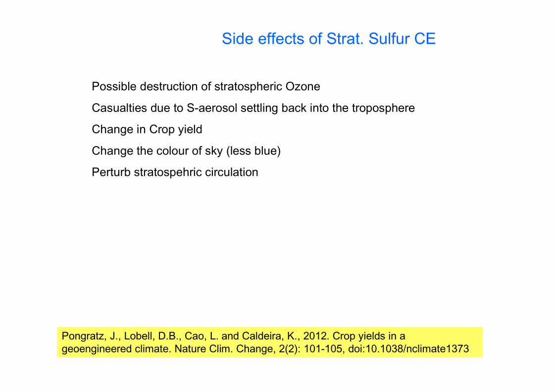
Side effects of Strat. Sulfur CE
Possible destruction of stratospheric Ozone
Casualties due to S-aerosol settling back into the troposphere
Change in Crop yield
Change the colour of sky (less blue)
Perturb stratospehric circulation
Pongratz, J., Lobell, D.B., Cao, L. and Caldeira, K., 2012. Crop yields in a geoengineered climate. Nature Clim. Change, 2(2): 101-105, doi:10.1038/nclimate1373
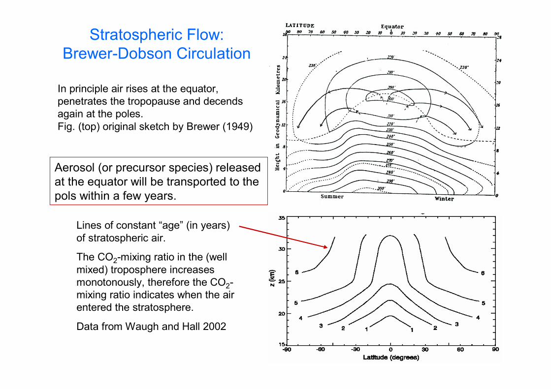
Stratospheric Flow: Brewer-Dobson Circulation
In principle air rises at the equator, penetrates the tropopause and decendsagain at the poles.Fig. (top) original sketch by Brewer (1949)
Lines of constant “age” (in years) of stratospheric air.
The CO2-mixing ratio in the (well mixed) troposphere increases monotonously, therefore the CO2-mixing ratio indicates when the air entered the stratosphere.
Data from Waugh and Hall 2002
Aerosol (or precursor species) releasedat the equator will be transported to thepols within a few years.

The Global sulfur cycle
Brasseur et al., 1999

Leverage Ratio of Stratospheric Aerosol
62
2
14 218
6 18 12
2
2 2
1 10
1 01325 5 1 105 266 10
9 81
441 10 5 266 10 7 99 10 8
29
280 2237 610
COCO Atm
Air
Atm EarthAtm
CO
CO
MM ppm ) MM
P A . Pa . mM . kgg . Nkg
M ppm ) . kg . kg Gt
M ppm ) GtCO GtC
Lev
Mass of Greenhouse Gas the effect of which is neutralizedR
Mass of material needed for the measure
Remember:
Assuming that 10 MtS/year can reduce the forcing by 4 W/m2 (optimistic)
we can say that this would approximately cancle the effect of CO2-doubling (from 280 ppm pre-industrial to 560 ppm, actually 3.7 W/m2).
Mass of 280 ppm of atmospheric CO2:
522372.24 10
10 Lev
GtR per year
Mt

How could Particle Sedimentation be prevented?
Prinziple of the „Light-Mill“(Lichtmühle)?
Radiation-source
Reflecting cold
Black warm
Wrong explanation 1:
Radiation pressure, Photons have momentum (p=E/c) but it is too small:
solar radiation: 10-4 W/cm2 3·1014 Photons/s, Momentum of a photon 10-27 kgm/s Force 3·10-13 Newtons (for 1 cm2)
Moreover: Momentum transfer to black surface: p, reflecting surface: 2p wrong rotational direction
Wrong explanation 2 (Wikipedia):
Warm layer of air at black surface provides larger pressure ...

Photophoretic Effects
Proposition: „Photophoretic Levitation“
Two mechanisms:
1) Temperature effect: Warm/cold surfaceProblem: Heat conduction within the (tiny) particle
2) Akkommodation coefficient effekt:
„sticky“/less „sticky“ surface
Beide Flächen wärmer als umgebende Luft
surface adsorbs air moleculestays longer assumes higherTemperature
surface reflects air moleculeimmediately short stay air molecule stays at
ambient temperature
FP
Akkommodation coefficient
= probability that a collidingair molecule assumes thetemperature of the particle
warm
cold
FP

Possible Solution of the Settling Problem: Photolevitation of the Particles
Keith, D.W. (2010) Photophoretic levitation of engineered aerosols for geoengineering, PNAS, www.pnas.org/cgi/doi/10.1073/pnas.1009519107
Thermal gradient force
Direction given by theorientation of the radiation field
Independent from theorientation of the particle
Akkommodation coefficienten-force
Direction given by the orientation of the particle
Problem: Orientation?
Special Levitation-disklets
Insolation
FP
warmcold
warm
Insolation
FP
„sticky“(=0.8)
less „sticky“(=0.6)
Orientation in theatmospheric electric field+ perhaps Earth magneticfield

Levitated Particles
Advantages and Disadvantages of levitated Particles:
• Much less mass required compared to sulfuric acid(ca. 1/10, mostly due to improved back-scattering)
• Less mass/year required due to longer lifetime e.g. 10 y. lifetime (instead of 1 y. for S-Aerosol): 1/100 of annual transport requirements
• Manufacturing and deployment of particles unclear.
• Long lifetime: How to get rid of the particles if desired?
Levitation force= gravity force particle floats
3 curves for different ratios of the emissivity in the visibleand thermal IR spectralranges, respectively
T0.04K T100K
Keith, D.W. (2010) Photophoreticlevitation of engineered aerosols forgeoengineering, PNAS, www.pnas.org/cgi/doi/10.1073/pnas.1009519107

Delivery of Particles to the Stratosphere
• Aircraft: Large Commercial Airliner (Boeing 747 Class)• Modified Gulfstream Class• New Design Airplane• Hybrid Airship• Gun (Mark 7 16")• Gun (Modernized Mark 7)• Rocket• Chimney (high towers)• Slurry Pipe• Gas Pipe • Other Techniques

McClellan et al. 2011

Sulfur Injection from Commercial Aircraft?
Laakso A., Partanen A.-I., KokkolaH., Laaksonen A., Lehtinen K.E.J. and Korhonen H. (2012), Stratospheric passenger flights are likely an inefficient geoengineeringstrategy, Environ. Res. Lett. 7, 034021 (7pp), doi:10.1088/1748-9326/7/3/034021.
Maximum negative forcingbelow 1.5 W/m2, even if fuelsulfur contents is icreased 50-fold (from 0.6 g/kg to 30 g/kg)

The „Coffin Corner“McClellan et al. 2011

High Towers

Source: Wikipedia,
Hughhunt
The SPICE - Project
Nature 485, May 24, 2012, p. 429.

Simplified Delivery of Sulfur to theStratosphere
Small Device
Vortex Rings (Smoke rings)
Exist also without smokeHelmholtz, H.: Über Integrale der hydro-dynamischen Gleichungen, welche den Wirbelbewegungen entsprechen.Journal für die reine und angewandteMathematik, Berlin; 1826, 25 - 55
Source: Wikipedia

What are Smoke Rings (Vortex Rings)?
A vortex ring(Drawing by Helmholtz)
Direction of motion of the entire ring
Vortex ring generator
r
R
Energy contentsproportional to volume (=22r2R) R3
Energy loss: proportional to surface area(=42rR) R2

Simplified Delivery of Sulfur to the Stratosphere– Smoke Rings (Vortex Rings)
A 10cm dia. smoke ring can travel 10-20m and still bring a card-house to collaps
The range of a smoke ring scales with the volume/surface ratio, i.e. with R
(Assuming R/r = constant)
changing R from 0.05m to 50m would change therange to Z=10 – 20 m to Z ≈ 10 - 20 km
Volume of a vortex ring (r=5m, R=50m): V≈24000 m3
SO2 - Weight ≈60 t Firing the device every 3 minutes would transport
1 million t of SO2 per year to stratosphere
Pressure increase needed to fire vortes ring:p ≈ 5mBar or V ≈ 15,000m3
30t of TNT (not bad for 60t of SO2, compare atillery)
Alternatives to TNT:30t of superheated water
1t of gasoline spray
200m
2R=100m
V≈3,000,000m3
Big Device
10
0m

Smoke Ring Delivery of SO2 (or Aerosol) to the Stratosphere
200m
2R=100m
Big Deviceunderground
10
0m
Direction of motion of the entire ring
30 t of TNT or30 t of superheatedwater or1 t of gasoline spray
Kinetic energy of Vortex: 3 MJ equivalent to burning
0.1 liter of gasoline
Room for improvement!
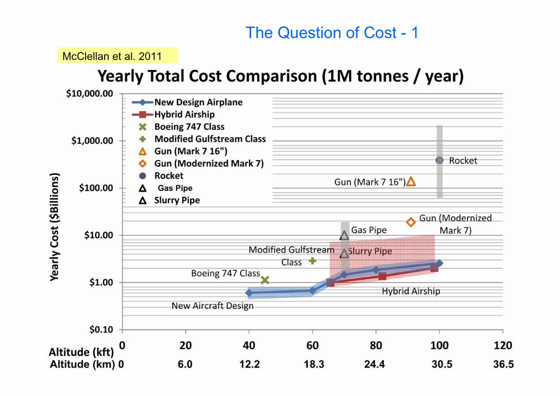
The Question of Cost - 1
McClellan et al. 2011
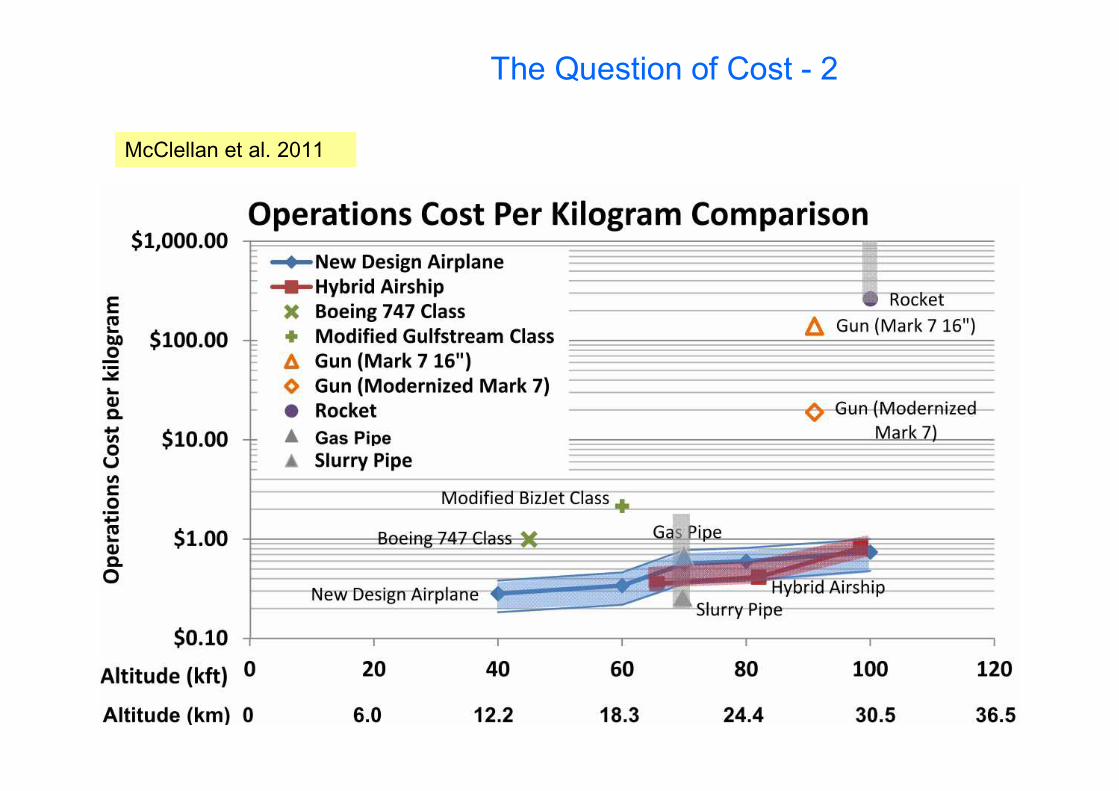
The Question of Cost - 2
McClellan et al. 2011

Gun Systems
McClellan et al. 2011

The „Side Effects“ of StratosphericGeoengineering

Stratospheric Heating
Absorption/scattering efficiencies for the SMALL/WIDE aerosol size distributions. Points are plotted at the mid-point of each wavelength interval.Ferraro A.J., Highwood E.J., and Charlton-Perez A. J. (2011), Stratospheric heating by potential geoengineeringaerosols, Geophys. Res. Lett. 38, L24706, doi:10.1029/2011GL049761

Stratospheric Heating
Ferraro A.J., Highwood E.J., and Charlton-Perez A. J. (2011), Stratospheric heating by potential geoengineering aerosols, Geophys. Res. Lett. 38, L24706, doi:10.1029/2011GL049761

Why Endanger Particles the Ozone Layer? (1)
Katalytic Ozone destruction:
X + O3 XO + O2
XO + O X + O2
net: O + O3
2O2
X/XO: „Katalyst“(e.g. OH/HO2, NO/NO2, Cl/ClO, Br/BrO)
HOX (Bates and Nicolet, 1950)NOX (Crutzen, 1970)ClOX (Stolarski and Cicerone, 1974;
Molina and Rowland, 1974)
Katalytic ozone destruction explainsdifference between measured (lower) and calcualted (ca. 3x higher) O3 –concentrations and their dependence on.
Particles?

Why Endanger Particles the Ozone Layer? (2)
1) Oxides of Nitrogen (one of the katalysts destroying ozone) is converted into (benign) nitiric acid.
NO2 + O3 NO3
NO2 + NO3 N2O5
N2O5 is converted to HNO3 at particle surfaces; “denoxification”.
N2O5 (g) + H2O (p) 2 HNO3 (p)
Reduced formation of ClONO2
2) Reactions at particle surfaces convert “benign” species (HCl, ClONO2), to ozone destruction-katalyst-spezies:
ClONO2 (g) + HCl (p) HNO3 (p) + Cl2 (g); Cl2 + h 2 Cl
ClONO2 (g) + H2O (p) HNO3 (p) + HOCl (g)
HOCl (g) + HCl (p) Cl2 (g) + H2O (p)
N2O5 (g) + HCl (p) HNO3 (p) + ClNO2 (g)
(p) bzw. (g) Reactands at particle or in the gas phase, respectively.

Reaction probability () of NOX and ClOX – Reservoir Species at Sulfuric AcidParticles as Function of the Temperature
Fortunately most of thereactions at H2SO4-particles only take placeat very low temperatures.
(polar winter)

Calculated Effect of stratospheric„Climate-Engineering Aerosol“ on the Ozone Layer
Additional ozone destruction rates due to different katalyst-species in AntarcticSpring, calculated for 2040-2050 and 2 Mt/year sulfur injection.
Tilmes, S., Garcia R.R., Kinnison D.E., Gettelman A., and Rasch P.J. (2009), Impact of geoengineeredaerosols on the troposphere and stratosphere, J. Geophys. Res., 114, D12305, doi:10.1029/2008JD011420.

Calculated Annual Variation of the Ozone column Density (in Dobson Units, DU) 2010-2020 vs. 2040-2050 over Antarctca and Arctic (2 Mt-S/year)
Tilmes, S., Garcia R.R., Kinnison D.E., Gettelman A., and Rasch P.J.(2009), Impact of geoengineered aerosolson the troposphere and stratosphere, J. Geophys. Res., 114, D12305, doi:10.1029/2008JD011420.
Antarctica (70-90oS) Arctic (70-90oN)
The chemical effect is proportional to the injected surface, thus (in good approximation) to the cooling effect!

Spektrum der Wissenschaft 4, 2012, S. 12-13
Other Side Effects …

The Colour of Geoengineered Skies
2) Clear sky scenario, ozone only atmosphere (background aerosol will make no noticeable change)
1) CE – Scenario: Compensation of global warming due to 2xCO2 by stratospheric sulfate aerosol
Source: E. Ahbe 2013Source: Eva Ahbe, Die Änderung der Himmelsfarbe durch Climate Engineering Maßnahmen, Bachelor Thesis, Univ. Heidelberg, 2013

Strong heating of lower stratosphere by the aerosol:• more stratospheric water vapour• changes in high clouds• effective forcing larger than instantaneous forcing
K
Kleinschmitt C., Boucher O., and Platt U. (2018), Sensitivity of the radiative forcing by stratospheric sulfur geoengineering to the amount and strategy of the SO2 injection studied with the LMDZ-S3A model, Atmos. Chem. Phys. 18, 2769–2786,
Our Simulations: Side Effects of Stratospheric Sulfur Injection
(Example: 10 MtS/a)

Strong heating by the aerosol:• stratospheric dynamics
(QBO) disturbed• poleward transport is impeded
(even larger particles)
Quasi-Biennial Oscillation (QBO)breaks down at 5 TgS/ainjection
Our Simulations: Side Effects of Stratospheric Sulfur Injection
Kleinschmitt C., Boucher O., and Platt U. (2018), Sensitivity of the radiative forcing by stratospheric sulfur geoengineering to the amount and strategy of the SO2 injection studied with the LMDZ-S3A model,Atmos. Chem. Phys. 18, 2769–2786,

Govindasamy et. al. Global and Planetary Change 37 (2003) 157–168
Consequences of CE Offseting 2xCO2 on the Global Temperature Distribution
oC

Consequences of CE on Global Precipitation Patterns
Change in daily precipitation column, (mm), J. Feichter et al. submitted
Blackstock et al. 2009
CE-measuresoffsetting the meanglobal temperature risecaused by 2xCO2

Annual MeanBurden of
Sulfate fromCE
Model Calculationsfor 2nd decade
(years 11-20 afterinitiation of CE)
HadGEM2 - Model
ModelE - Model
Jones A., Haywood J., Boucher O., Kravitz B., and Robock A. (2010), Geoengineering by stratospheric SO2 injection: results from the Met Office HadGEM2 climate model and comparison with the Goddard Institute for Space Studies ModelE, Atmos. Chem. Phys., 10, 5999–6006.

Change in Radiative Forcing due to CEModel Calculations for 2nd
decade (years 11-20 afterinitiation of CE)
HadGEM2 - Model
ModelE - Model
Jones A., Haywood J., Boucher O., Kravitz B., and Robock A. (2010), Geoengineering by stratospheric SO2 injection: results from the Met Office HadGEM2 climate model and comparison with the Goddard Institute for Space Studies ModelE, Atmos. Chem. Phys., 10, 5999–6006.

Changes in Temperature and Precipitation
A1B Scenario(IPCC)
–
A1B+CE (HadGEM2 –Model)
A1B Scenario(IPCC)
–
A1B+CE (ModelE –Model)
PrecipitationJune – July - August
Jones A., Haywood J., Boucher O., Kravitz B., and Robock A. (2010), Geoengineering by stratospheric SO2injection: results from the Met Office HadGEM2 climate model and comparison with the Goddard Institute for Space Studies ModelE, Atmos. Chem. Phys., 10, 5999–6006.
Annual mean Temp. 2nd decade
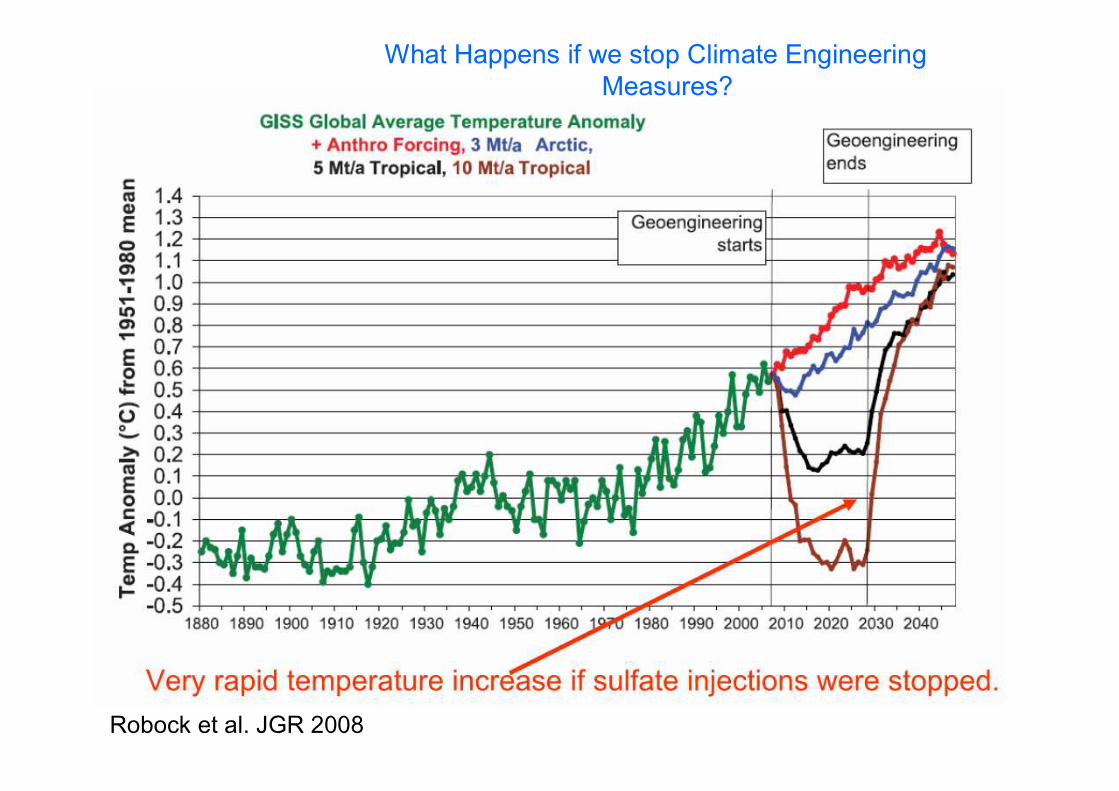
Robock et al. JGR 2008
What Happens if we stop Climate Engineering Measures?

Advantages and Problems of Stratospheric ParticleCE
Advantages:
Relatively cheap to implement (estimated 1-10 billion $ annually)
Very large leverage factor (about 2105 per year)
Problems:
Very difficult to achive optimum particle size
Likely destruction of stratospheric aerosol
Casualties due to sulfate-aerosol (20,000 annually per million ton of S-aerosol)
No more blue sky anywhere on the globe
Astronomical observations will be affected

Summary
• A closer look to even the most promising CE-technique i.e. stratospheric aerosol reveals, substantial, fundamental problems(how to inject, influence on the ozone layer, required mass).
• Further research on the problem – in particularon nucleation processes - is required.
• Sulfuric acid particles are not optimal becauseof their chemical effects
• completely different approaches – speciallyengineered particles – could be promising.
• Leverage factors of (1-3)106 couldtheoretically be reached.