6. description of the preferred undertaking
TRANSCRIPT

E n v i r o n m e n t a l A s s e s s m e n t
chapter 6. description of the preferred undertaking
6-1
6. Description of the Preferred Undertaking
This chapter describes the conceptual design of the preferred undertaking and the phasing plan and techniques
proposed to construct the undertaking.
6.1 Overview of the Conceptual Design
The conceptual design for the DMNP includes the following components:
Flood protection features;
Sediment, debris, and ice management;
Naturalization;
Public realm and open space; and
Integration with the Lower Don Lands planning and servicing.
The various components are described in their built-out state in the following sections. Minimum design
requirements for these components are described throughout Section 6.1 in italicized bold text; these
requirements reflect approximate dimensions (including area) that were developed during conceptual design and
must be maintained during functional and detailed design. The minimum design requirements are summarized at
the end of this section in Table 6-4, along with the technical issues and constraints that have influenced the design,
including: existing conditions; the fixed components of the design; and opportunities for flexibility.
All components of the design have been developed with Waterfront Toronto’s Sustainability Framework in mind. As
described in Chapter 2, the Sustainability Framework provides the overarching corporate policy for the integration
of sustainability principles into all facets of decision making and project delivery. Table 6-1 identifies how the
objectives of the Sustainability Framework have been incorporated into the design.
Table 6-1 How Sustainability is Addressed in the Design
Waterfront Toronto Sustainability Framework Objectives How the Objective is Addressed in the Conceptual Design
Recapture Value of Abandoned and Underused Sites
Redevelop abandoned sites
Creation of a new valley system will involve redevelopment of
contaminated sites that are either abandoned or underused and
allow for reuse of adjacent lands that are currently underused due to
flooding constraints
State-of-the-Art Integrated Soil Management
Safe and effective management of contaminated soils.
Treatment of contaminated soils at a nearby Soil Recycling Facility
is one option being considered for how to manage soils that are
excavated from the site
Protect Groundwater from Contamination
Minimize risks from contaminated sites.
Implementation of Waterfront Toronto’s Integrated Groundwater
Management Soil Strategy.
The design of the river valley includes a permeable or impermeable
barrier to isolate contaminated groundwater from clean soils and
water
Construction techniques have also been identified to ensure that
clean stormwater does not intercept contaminated groundwater
during excavation
Enhanced Terrestrial and Aquatic Habitat
Site design that accommodates animal and aquatic habitat.
Habitat enhancement along the water’s edge and more wetland.
Create and maintain networks of natural systems both within the site
and beyond its boundaries including linking the Don River corridor,
Cherry Beach, Lake Ontario Park and the Leslie Street Spit.
Infrastructure creation that facilitates understanding, appreciation,
and use of fish and wildlife resources
Over 33 ha of terrestrial and aquatic habitat are being created,
including 13 ha of wetland habitat, 12 ha of permanent aquatic
habitat, and 8 ha of terrestrial habitat
All 33 ha are either in-water or along the water’s edge and
contribute to improved connectivity between the site and adjacent
natural systems
Existing infrastructure within the Keating Channel will be redesigned
to provide for enhanced fish habitat
E n v i r o n m e n t a l A s s e s s m e n t
chapter 6. description of the preferred undertaking
6-2
Waterfront Toronto Sustainability Framework Objectives How the Objective is Addressed in the Conceptual Design
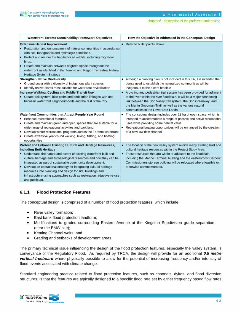
Extensive Habitat Improvement
Restoration and enhancement of natural communities in accordance
with soil, topographic and hydrologic conditions.
Protect and restore the habitat for all wildlife, including migratory
birds.
Create and maintain networks of green space throughout the
waterfront as identified in the Toronto and Region Terrestrial Natural
Heritage System Strategy
Refer to bullet points above
Strengthen Native Biodiversity
Ground cover with a diversity of indigenous plant species.
Identify native plants most suitable for waterfront revitalization
Although a planting plan is not included in this EA, it is intended that
plants used to establish the naturalized communities will be
indigenous to the extent feasible
Increase Walking, Cycling and Public Transit Use
Create trail system, bike paths and pedestrian linkages with and
between waterfront neighbourhoods and the rest of the City.
A cycling and pedestrian trail system has been provided for adjacent
to the river within the river floodplain. It will be a major connecting
link between the Don Valley trail system, the Don Greenway, and
the Martin Goodman Trail, as well as the various natural
communities in the Lower Don Lands
Waterfront Communities that Attract People Year Round
Enhance recreational features.
Create and maintain green and open spaces that are suitable for a
wide range of recreational activities and park land.
Develop winter recreational programs across the Toronto waterfront
Create extensive year-round walking, biking, fishing, and boating
opportunities
The conceptual design includes over 13 ha of open space, which is
intended to accommodate a range of passive and active recreational
uses while providing some habitat value
Recreational boating opportunities will be enhanced by the creation
of a new low flow channel
Protect and Enhance Existing Cultural and Heritage Resources,
Including Built Heritage
Understand the nature and extent of existing waterfront built and
cultural heritage and archaeological resources and how they can be
integrated as part of sustainable community development.
Develop an operational strategy for integrating cultural heritage
resources into planning and design for site, buildings and
infrastructure using approaches such as restoration, adaptive re-use
and public art.
The location of the new valley system avoids many existing built and
cultural heritage resources within the Project Study Area.
Those resources that are within or adjacent to the floodplain,
including the Marine Terminal building and the easternmost Harbour
Commissioners storage building will be relocated where feasible or
otherwise commemorated.
6.1.1 Flood Protection Features
The conceptual design is comprised of a number of flood protection features, which include:
River valley formation;
East bank flood protection landform;
Modifications to grades surrounding Eastern Avenue at the Kingston Subdivision grade separation
(near the BMW site);
Keating Channel weirs; and
Grading and setbacks of development areas.
The primary technical issue influencing the design of the flood protection features, especially the valley system, is
conveyance of the Regulatory Flood. As required by TRCA, the design will provide for an additional 0.5 metre
vertical freeboard where physically possible to allow for the potential of increasing frequency and/or intensity of
flood events associated with climate change.
Standard engineering practice related to flood protection features, such as channels, dykes, and flood diversion
structures, is that the features are typically designed to a specific flood rate set by either frequency based flow rates

E n v i r o n m e n t a l A s s e s s m e n t
chapter 6. description of the preferred undertaking
6-3
or historically based flow rates or water levels. In doing so, it has been common practice to address the varying
levels of uncertainty that exist by including a freeboard to any design height developed. This freeboard is a similar
approach to that of applying factors of safety common in assessing uncertainties in other engineering designs. For
flood control structures, this freeboard has normally been set at a minimum additional height of 0.3 metres above
that defined for the flood design.
In the case of the Lower Don flood control river projects, the stressor of climate change is an additional requirement
to be included. Inclusion of climate change impacts at a local scale poses many technical and scientific challenges
given the current uncertainty within climate change science. To address these uncertainties, a flow sensitivity
analysis was undertaken on the Don River to look at impacts that could occur should climate change result in a 10
to 15 percent increase in the design flood being used to size the flood control structures. This analysis was based
upon the limited understanding of the projected future science and input from external expertise. The resulting
sensitivity analysis defined that up to an additional 20 centimetres of flood levels may be anticipated within this
reach of the Don River under future climates. This factor of safety was added to the 0.3 metre standard freeboard
to define an overall freeboard of 0.5 metres. It is acknowledged that the 0.5 metre vertical freeboard may not be
achievable at the Lake Shore Boulevard crossing and at Eastern Avenue with the Kingston Subdivision grade
separation.
6.1.1.1 River Valley Formation
Creation of a new river valley is the primary means of conveying flood events up to the Regulatory Flood. For the
purpose of describing different areas of the river, the river design has been broken into four reaches and two sub-
reaches (the latter depicted by the two spillways), as illustrated in Figure 6-1.

6-4
Figure 6-1 Don River Reaches

E n v i r o n m e n t a l A s s e s s m e n t
chapter 6. description of the preferred undertaking
6-5
Common to all reaches is the need for underlying stabilization of the river bed, valley walls, and levees to limit or
prevent movement. Specifically, stabilization will ensure that most flood events and the associated shear stresses
do not erode into the underlying contaminated soils, undermine adjacent development blocks, nor result in the
destruction of the lake-connected wetlands. Under major flooding (Regional flood) events it is anticipated that the
lake-connected wetlands and levee systems will experience some degree of damage while contaminated soils will
remain protected. The overall type and extent of stabilization works will be defined through detailed hydraulic
modelling. These stabilization features will be overtopped with a clean layer of fill and soil with vegetation (if
applicable) to prevent the movement of contaminated soil and groundwater into the naturalized areas. The depth of
clean fill and soil cover will be determined through a separate risk assessment and risk management (RA/RM)
process, to be conducted in accordance with O. Reg. 153/04.
Stabilization and subsurface erosion control methods will be designed for the valley feature where considerable
shear stresses are expected. Stone is also proposed for bridge footings to provide scour protection, within the
Keating Channel to stabilize the dockwalls, and for large levees to ensure stability. The river bottom will be heavily
stabilized along most of its length in all reaches of the river using a combination of gravel, sand, and cobble to
prevent downcutting and to stabilize the levees as well.
For detailed assessment of the preferred undertaking, we have assumed that a barrier will be installed beneath the
river channel and the wetlands to prevent the migration of contaminated groundwater into surface water. We have
further assumed that this will require over-excavation of the river channel footprint and wetlands by 1.0 to 1.5
metres to facilitate the installation of such a barrier. This depth will be confirmed through the RA/RM to
accommodate whatever form of barrier is adopted. The flexibility and maximum degree to which downcutting is
permissible will be set by the depth of cover over contaminated soils as defined by the RA/RM.
Don River Reach 1
Reach 1 extends from upstream of the CN Rail bridge south to Lake Shore Boulevard East, as shown in Figure 6-
2. This will remain a fully engineered channel with no low flow channel and floodplain features. The length of this
reach is approximately 290 metres and the channel width ranges from approximately 60 to 80 metres within
the sediment trap area. The width of the valley will be approximately 300 metres, measured from the top of
the valley slope. To address the requirements for sediment management, the sediment trap will be
deepened to approximately 70 metres above sea level (mASL). The area that is not used for the sediment
trap will be situated at an elevation of approximately 72 metres.

E n v i r o n m e n t a l A s s e s s m e n t
chapter 6. description of the preferred undertaking
6-6
Figure 6-2 Reach 1
A sediment and debris management facility is also planned for the west bank of Reach 1, as described in Section
6.1.2.4. In addition, a flood protection feature on the east bank of the Don River will be located between the CN
Rail bridge and the Keating Yard to permanently eliminate the risk of flooding to the east. This feature will require
a minimum crest elevation of approximately 79.75 metres at the upstream end, which will drop by
approximately 0.5 metres at the downstream end. The west side slope (wet side) of the landform will possess a
maximum 10 percent grade, while the east side slope (dry side) will possess a maximum 5 percent grade. These
grades, that are a 5 percent dry-side, grade will allow for some continued use and occupation of the existing
operations on the property, though it will necessitate establishing a new roadway access from the Don Roadway or
Lake Shore Boulevard, modifying the existing loading bays and parking area, and relocating the hydro station
infrastructure on the northwest corner of the property. No development or deep rooted plantings will be permitted
on the entire footprint of the landform. The landform will need to be keyed in appropriately to the height of land
near Lake Shore Boulevard in the south and the elevated railway embankment in the north.
In the event that the site undergoes redevelopment, additional alternatives to provide necessary flood protection will
be sought through a future site planning process.

E n v i r o n m e n t a l A s s e s s m e n t
chapter 6. description of the preferred undertaking
6-7
Current hydraulic modelling has identified a spill related to minor flooding depths through the Eastern Avenue
underpass of the CN Rail line (Kingston Subdivision) east of the Don River during the regulatory event. While flood
depths at this location are shallow, some minor grade modifications may be required to the area southeast of
Eastern Avenue in the vicinity of the CN Rail line (east of the Don River) to eliminate this potential spill of flood
waters on the BMW site.
Reach 1 will have a completely armoured edge along the entire channel using sheet piling, with the exception of the
backwater area adjacent to the sediment and debris management facility. Other modifications within this reach that
are required to improve flood conveyance include removal of the Hydro One utility bridge that is approximately 40
metres south of the CN Rail bridge.
Given the constraints associated with conveying the Regulatory Flood through Reach 1, there is no flexibility for
modifying the dimensions of the channel unless modifications allow for additional conveyance capacity. Given the
hydraulic influence of the Gardiner Expressway ramps (to the Don Valley Parkway) there is an opportunity to
provide additional conveyance capacity should the Gardiner Expressway (currently subject to its own
Environmental Assessment) be reconfigured or removed.
6.1.1.2 Don River Reach 2 and Keating Channel (Reach 2a)
Reach 2 extends from the Lake Shore Boulevard crossing south to the realigned Commissioners Street, as shown
in Figure 6-3. This reach is a transitional area from the heavily managed reach upstream of the Lake Shore bridge
to the new naturalized valley south of the new Commissioners Street bridge. Reach 2 will consist of a river channel
and a connected and functioning floodplain within the new valley system. The length of Reach 2 is
approximately 260 metres. The width of the valley will be approximately 150 metres, measured from the
top of the valley slope. The width of the low flow channel, measured from the top of the banks, is
approximately 120 metres at its widest point and transitions to a width of approximately 15 metres north of
the future Commissioners Street bridge.
Figure 6-3 Reach 2
E n v i r o n m e n t a l A s s e s s m e n t
chapter 6. description of the preferred undertaking
6-8
To mediate the transition between Reach 1 and Reach 2, there will be walls or riprap on the east and west sides,
likely built with large rock to manage the high stresses associated with the transition. This type of stabilization will
likely be covered with a naturalized veneer to support habitat functions. This transition will also provide a required
ice management function by providing a place for ice to collect and break up, with capacity for overflow into the
Keating Channel if an ice jam should occur. At the downstream end of the reach, stabilization will also be provided
to protect the Commissioners Street bridge footings. Stabilization for the valley wall will consist of engineering edge
(e.g., sheetpile) on the eastern side underlain by soil and vegetation.
This reach has limited flexibility in alignment or configuration as it is set by the location of the Lake Shore Boulevard
crossing, the Commissioners crossing (including the associated ice management function), and the
elevations/function of the sideflow weir in the Keating Channel.
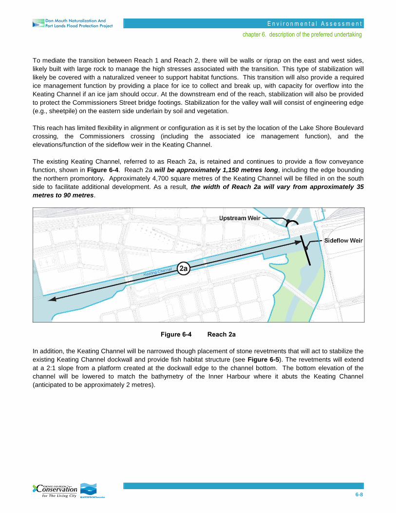
The existing Keating Channel, referred to as Reach 2a, is retained and continues to provide a flow conveyance
function, shown in Figure 6-4. Reach 2a will be approximately 1,150 metres long, including the edge bounding
the northern promontory. Approximately 4,700 square metres of the Keating Channel will be filled in on the south
side to facilitate additional development. As a result, the width of Reach 2a will vary from approximately 35
metres to 90 metres.
Figure 6-4 Reach 2a
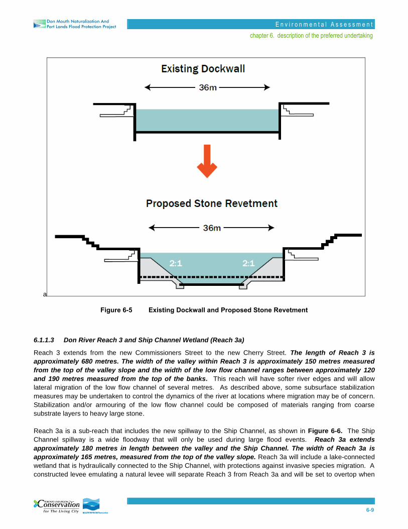
In addition, the Keating Channel will be narrowed though placement of stone revetments that will act to stabilize the
existing Keating Channel dockwall and provide fish habitat structure (see Figure 6-5). The revetments will extend
at a 2:1 slope from a platform created at the dockwall edge to the channel bottom. The bottom elevation of the
channel will be lowered to match the bathymetry of the Inner Harbour where it abuts the Keating Channel
(anticipated to be approximately 2 metres).
E n v i r o n m e n t a l A s s e s s m e n t
chapter 6. description of the preferred undertaking
6-9
a
Figure 6-5 Existing Dockwall and Proposed Stone Revetment
6.1.1.3 Don River Reach 3 and Ship Channel Wetland (Reach 3a)
Reach 3 extends from the new Commissioners Street to the new Cherry Street. The length of Reach 3 is
approximately 680 metres. The width of the valley within Reach 3 is approximately 150 metres measured
from the top of the valley slope and the width of the low flow channel ranges between approximately 120
and 190 metres measured from the top of the banks. This reach will have softer river edges and will allow
lateral migration of the low flow channel of several metres. As described above, some subsurface stabilization
measures may be undertaken to control the dynamics of the river at locations where migration may be of concern.
Stabilization and/or armouring of the low flow channel could be composed of materials ranging from coarse
substrate layers to heavy large stone.
Reach 3a is a sub-reach that includes the new spillway to the Ship Channel, as shown in Figure 6-6. The Ship
Channel spillway is a wide floodway that will only be used during large flood events. Reach 3a extends
approximately 180 metres in length between the valley and the Ship Channel. The width of Reach 3a is
approximately 165 metres, measured from the top of the valley slope. Reach 3a will include a lake-connected
wetland that is hydraulically connected to the Ship Channel, with protections against invasive species migration. A
constructed levee emulating a natural levee will separate Reach 3 from Reach 3a and will be set to overtop when

E n v i r o n m e n t a l A s s e s s m e n t
chapter 6. description of the preferred undertaking
6-10
flood events reach the 25 to 50 year flood elevations. Actively operating the upstream weir in Reach 1 could further
reduce the frequency of overtopping from Reach 3 to 3a as desired/required. Flood waters will then flow into the
Ship Channel through openings under the Basin Street causeway. The spillway will require stabilization along the
valley sides, at the Ship Channel, and under the overflow levee.
Figure 6-6 Reach 3 and 3a
6.1.1.4 Don River Reach 4
Reach 4 is the mouth of the river, shown in Figure 6-7. The length of Reach 4 is approximately 490 metres. At
the downstream end, where the river mouth opens to the Inner Harbour and serves as the main outlet to
the lake, the low flow channel encompasses nearly the entire width of the floodplain, equal to
approximately 220 metres from the top of the valley slope. Upstream, the low flow channel narrows to a
width of approximately 190 metres measured from the top of the banks where it connects to Reach 3.
There will be minimal or no stabilization in Reach 4 along the river channel edges, with tolerance for migration of
the channel. This minimal level of stabilization will transition to a higher degree of stabilization at the harbour-
exposed edges.
E n v i r o n m e n t a l A s s e s s m e n t
chapter 6. description of the preferred undertaking
6-11
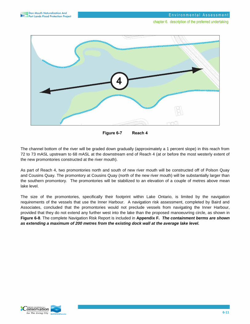
Figure 6-7 Reach 4
The channel bottom of the river will be graded down gradually (approximately a 1 percent slope) in this reach from
72 to 73 mASL upstream to 68 mASL at the downstream end of Reach 4 (at or before the most westerly extent of
the new promontories constructed at the river mouth).
As part of Reach 4, two promontories north and south of new river mouth will be constructed off of Polson Quay
and Cousins Quay. The promontory at Cousins Quay (north of the new river mouth) will be substantially larger than
the southern promontory. The promontories will be stabilized to an elevation of a couple of metres above mean
lake level.
The size of the promontories, specifically their footprint within Lake Ontario, is limited by the navigation
requirements of the vessels that use the Inner Harbour. A navigation risk assessment, completed by Baird and
Associates, concluded that the promontories would not preclude vessels from navigating the Inner Harbour,
provided that they do not extend any further west into the lake than the proposed manoeuvring circle, as shown in
Figure 6-8. The complete Navigation Risk Report is included in Appendix F. The containment berms are shown
as extending a maximum of 200 metres from the existing dock wall at the average lake level.

E n v i r o n m e n t a l A s s e s s m e n t
chapter 6. description of the preferred undertaking
6-12
Figure 6-8 Manoeuvring Circles Associated with Promontories
6.1.1.5 Operation of Keating Channel Weirs
To improve flood conveyance, the existing Lake Shore Boulevard and Harbour Lead bridges will be
lengthened from the two bays that currently exist to include a total of five bays, for a total length of
approximately 120 metres. The soffit heights for the lengthened portions of the bridges will range between
approximately 77 and 78 metres. The design plans for the proposed extension of the roadway (Lake Shore
Boulevard) and the railway (Harbour Lead) bridges, which originate from the Lower Don Lands Infrastructure
Municipal Class EA, are shown in Appendix G.
The three eastern bays will provide conveyance for river flows continuing straight south into the new primary river
outlet. A weir structure will be placed just north of the Lake Shore Boulevard / Harbour Lead crossing and will
regulate water to allow the passage of flood events through the Keating channel. It is proposed that an adjustable
weir will be installed to allow for flexibility in operation. The maximum height of the new weir structure will be
set at approximately 76 metres and a bed elevation of approximately 71 metres, which will provide
conveyance of flood events greater than the two-year event.
A sideflow weir will be installed to the south of the Lake Shore Boulevard crossing to permit flows greater
than the two-year event to pass into the Keating Channel from the east, with a bed elevation of
approximately 71 metres and a crest height of approximately 75 to 76 metres. It will likely feature a fixed crest

E n v i r o n m e n t a l A s s e s s m e n t
chapter 6. description of the preferred undertaking
6-13
with a drop inlet to allow for decanting of some of the surface water from the main channel during flow events in the
range of 15 to 25 cubic metres per second up to the two-year flood to help with circulation in the Keating Channel
and prevent stagnation. The functional or detailed design of the river will confirm the configuration, type, and
operation of the weirs.
6.1.1.6 Grading and Setbacks of Development Areas
To permanently remove flood risk from future development areas, the lands on either side of the river will be
elevated approximately 1 to 2 metres above existing elevations. New development areas as defined within the
Provincial Policy Statement (PPS, 2005) will be required to be set back from the top of valley slope of the
new river valley by 10 metres horizontally. Figure 6-9 shows the setbacks associated with the adjacent
development areas and the approximate grading relative to this new regulatory floodplain. A detailed grading plan
is included in Appendix H.

6-14
Figure 6-9 Regulatory Event Level and Setbacks from Floodplain
E n v i r o n m e n t a l A s s e s s m e n t
chapter 6. description of the preferred undertaking
6-15
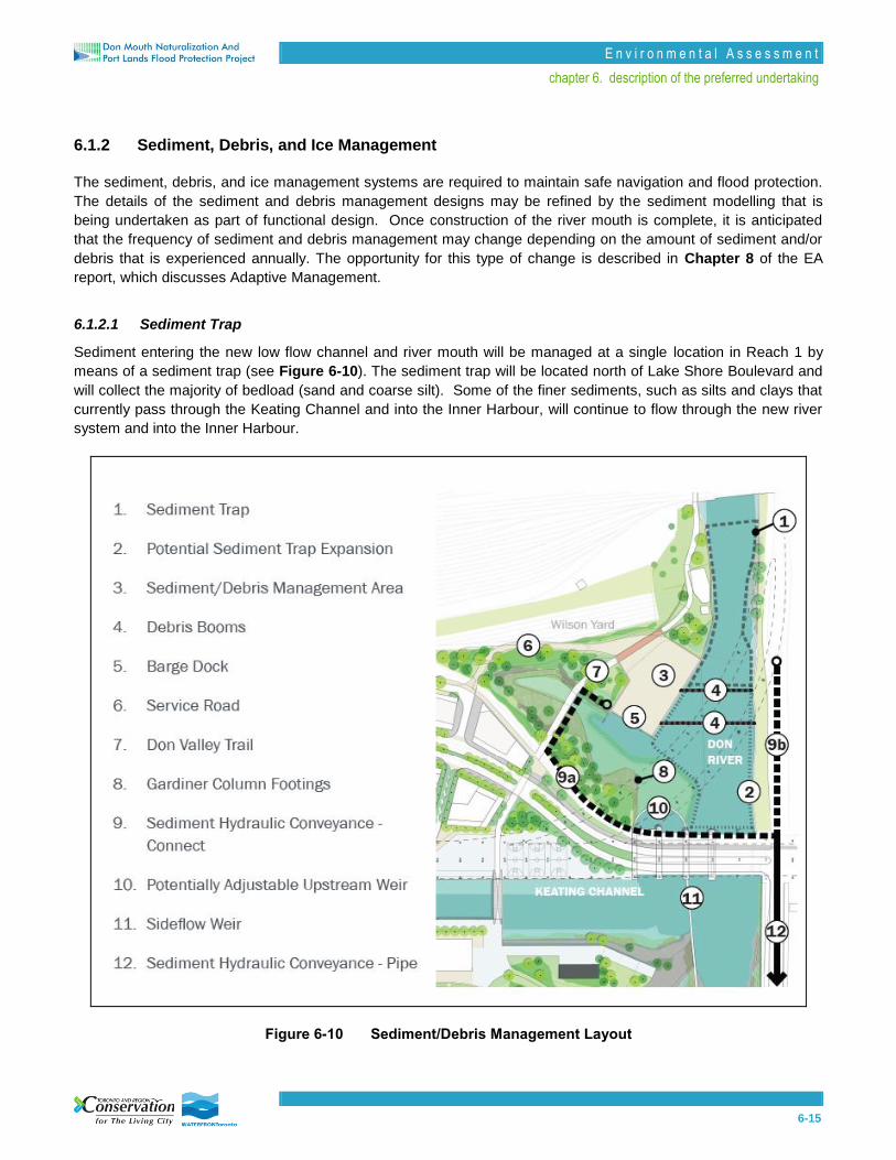
6.1.2 Sediment, Debris, and Ice Management
The sediment, debris, and ice management systems are required to maintain safe navigation and flood protection.
The details of the sediment and debris management designs may be refined by the sediment modelling that is
being undertaken as part of functional design. Once construction of the river mouth is complete, it is anticipated
that the frequency of sediment and debris management may change depending on the amount of sediment and/or
debris that is experienced annually. The opportunity for this type of change is described in Chapter 8 of the EA
report, which discusses Adaptive Management.
6.1.2.1 Sediment Trap
Sediment entering the new low flow channel and river mouth will be managed at a single location in Reach 1 by
means of a sediment trap (see Figure 6-10). The sediment trap will be located north of Lake Shore Boulevard and
will collect the majority of bedload (sand and coarse silt). Some of the finer sediments, such as silts and clays that
currently pass through the Keating Channel and into the Inner Harbour, will continue to flow through the new river
system and into the Inner Harbour.
Figure 6-10 Sediment/Debris Management Layout

E n v i r o n m e n t a l A s s e s s m e n t
chapter 6. description of the preferred undertaking
6-16
The sediment trap area will be approximately 1.5 metres deeper than the rest of the river channel (at an
elevation of 70 mASL). The final configuration, size and depth of the sediment trap will be determined during the
functional or detailed design of the river. It is anticipated that the amount of sediment trapped annually will be equal
to the current annual volumes of sediment that are dredged from the Keating Channel, which is approximately
35,000 to 40,000 cubic metres. To effectively manage this volume of sediment, it is anticipated that the trap will
need to be emptied 3 to 5 times a year or as needed following large flood events. Conversely, the sediment trap
may need to be enlarged or deepened to trap a greater volume of sediment. Reach 1 has sufficient capacity to
reduce the frequency of dredging by increasing the dimensions of the trap.
Based on the current design, it is not anticipated that secondary sediment management downstream from the
sediment trap within the low flow channel, wetlands, or the Inner Harbour will be required. Upon commencing
operations of the relocated sediment management system, sediment removal within the new trap will be monitored
to determine the efficiency of the trap, whether adjustments need to be made to operations (i.e., frequency of
dredging) or to the physical size of the trap, and also whether secondary sediment management downstream is
required. This activity will follow the adaptive management procedures described in Chapter 8.
Additional maintenance dredging is also anticipated under the westernmost elevated CN Rail bridge span north of
the sediment and debris management facility to maximize hydraulic conveyance and improve the area’s function as
fish habitat.
A hydraulic dredge will be used to remove the bedload from the sediment trap. Hydraulic dredges use suction to
remove a mixture of dredged material and water from the channel bottom. They typically have a cutterhead on the
suction end, which is a mechanical device with rotating blades or teeth to break up or loosen sediment so that it can
be sucked through the dredge (see Figure 6-11). Many hydraulic dredges are also self-propelled (barge-mounted)
and low-profile to allow for access under bridges, which are required capabilities for use in this area.
Figure 6-11 Example of a Hydraulic Dredge

E n v i r o n m e n t a l A s s e s s m e n t
chapter 6. description of the preferred undertaking
6-17
With respect to upland needs near the trap, the hydraulic dredging requires:
an off-channel barge slip for docking during non-use periods (or upland dry-docking, which would
require more frequent use of a crane to place the barge in and out of the channel);
a portion of the upland footprint for miscellaneous equipment storage (e.g., flexible piping and floats
needed during dredging activities); and
an area for connecting flexible piping from the dredge barge to a more permanent, hardpiped utility for
further transport to another location with the possibility of a booster system if required. It is anticipated
that a 25 to 30 centimetres diameter pipe would be required for the sediment slurry generated by a
hydraulic dredge.
6.1.2.2 Sediment Conveyance System
As mentioned above, the water/sediment slurry generated by hydraulic dredging requires operation of a
conveyance piping system, shown in Figure 6-10 as location 9a and 9b. A flexible floating pipe connected to the
hydraulic dredge barge will transition to permanent fixed piping utilities that run along the Don Roadway to the
Basin Street causeway at the mouth of the Ship Channel Wetland (see Figure 6-12). The slurry must then be
dewatered before the remaining sediment can be disposed. A flexible pipe will carry the slurry from the Ship
Channel wetland to a barge-mounted hydrocyclone, which is a dewatering system that spins the slurry to separate
the water and sediment and sort the sediment by grain size (see Figure 6-13).
Figure 6-12 Proposed Location of Sediment Dewatering Facilities

E n v i r o n m e n t a l A s s e s s m e n t
chapter 6. description of the preferred undertaking
6-18
Figure 6-13 Example of a Hydrocyclone
It is anticipated that regular maintenance of the slurry pipe will be required to ensure that it does not become clogged.
A second redundant slurry pipe parallel to the primary pipe will be installed to allow work to continue in the event of a
blockage or replacement. Should maintenance become cost-prohibitive, an alternate location for the slurry pipe or its
collection point that requires a shorter length of pipe, and thus easier maintenance, may be identified and
implemented such as the eastern end of the Keating Channel, south of the Lake Shore Boulevard crossing.
6.1.2.3 Sediment Disposal and Re-Use
As is done currently, dredged material from the river mouth will be disposed of at the Confined Disposal Facility (CDF)
at Tommy Thompson Park using towed, bottom-dumping scows. There is one embayment (Cell 3) at the CDF that is
projected to have capacity for up to 40 years and is a viable location for future sediment disposal from a trap.
Should dredged material be uncontaminated or readily treated, re-use of trapped sediments could be considered
for use as fill or habitat material. This reuse could increase the projected life expectancy at Cell 3.
6.1.2.4 Sediment / Debris Management Area
Debris will be managed in Reach 1 of the river. Two debris management booms will be placed across the entire
width of the channel at the approximate locations shown in Figure 6-10 above. These booms will be used to corral
floating debris after flood events and at other times as needed. Any woody debris that is not caught by the booms
and travels farther downstream may be left in place. The need and methods for removal of other debris will be
assessed following monitoring of flood events.

E n v i r o n m e n t a l A s s e s s m e n t
chapter 6. description of the preferred undertaking
6-19
Corralled debris will be removed by a crane sited at location 3 as shown on Figure 6-10 above. The debris will be
dewatered and sorted on a small yard on the west side of the river for either offsite disposal and/or reused for
habitat purposes. The total footprint of the debris management area is approximately 45 by 90 metres. This
concept allows for an approximate 34 metre turning diameter, sufficient to allow for most if not all large trucks.
The sediment / debris management area must also provide space for the following:
Debris skimmers and dockside cranes to remove debris;
Storage for debris and to allow trucks to manoeuvre for loading debris for disposal;
Equipment maintenance shed and operations building;
Storage for floating debris booms and maintenance of booms;
Room for dockside loading onto trucks after material has dried on land; and
Real-time stream discharge monitoring station (recommended for active management of the
operational weir at Lake Shore Boulevard).
A restricted access boat ramp will allow boats to be launched or removed from this location as needed (such as
Toronto Police Marine Unit access boats and electrofishing boats), along with dredging equipment used for
sediment management and debris skimmers used for debris management.
6.1.2.5 Ice Management
Ice management features are designed to prevent a concurrent risk of a flood event that is exacerbated by ice
accumulations, and to reduce the risk to bridge pylons and other infrastructure within the floodplain environment.
Within Reach 2, the stabilized transition between the Lake Shore Boulevard crossing and the Commissioners
Street crossing will provide a place for ice to collect and break up, with capacity for overflow into the Keating
Channel if an ice jam should occur (see Figure 6-3). Specifically, the design is intended to accommodate complete
damming of the floodplain from ice, with overflow being conveyed over an upstream weir at the Keating Channel. At
the downstream end of the reach, armouring may also be provided to protect the Commissioners Street bridge
abutments and columns from ice build-up.
6.1.3 Naturalization
Approximately 33 hectares of naturalized area will be created as part of the conceptual design and consist of the
following habitat types, as identified during Step 4 of the EA:
8 hectares of terrestrial / open space habitat, including open space and valley slope transitions;
13 hectares of wetland habitat, including levee systems, lake-connected wetlands; and
12 hectares of permanent aquatic habitat.
These habitat types are comprised of the vegetation communities identified in Section 5.1.2.2 of Chapter 5, which
include: upland forest and/or thicket; treed swamp; thicket swamp; meadow marsh; emergent marsh; and
submergent marsh.
There are a number of key principles that have guided the design proposed for the naturalized component of the
DMNP, and that will continue to influence the design following the EA. These principles are:
1. That the principal source of water to sustain the proposed aquatic habitat and lake-connected
wetlands at the mouth of the Don is Lake Ontario based on the known cycle of lake level

E n v i r o n m e n t a l A s s e s s m e n t
chapter 6. description of the preferred undertaking
6-20
fluctuations (seasonal range of +/-1 metre). The hydraulic connections to these wetlands will
primarily involve feeder channels between the low flow channel and the downstream end of the
wetlands.
2. That the smaller lake-connected wetlands in Reaches 3 and 4 will be separated from the channel
primarily by an artificial levee system which forms the banks of the low flow channel. Barriers may
or may not be placed at the mouth of the wetland feeder channels depending on the need to
exclude carp from these areas. Alternatively, variations in microtopography along these feeder
channels will also be used to act as barriers to carp movement into the smaller lake-connected
wetlands. For the larger lake-connected wetland in Reach 3a, which will be connected
hydraulically to the lake through the Ship Channel, a broader range of passive and active
measures will be considered to ensure that carp are excluded from this area.
3. In addition to principle number 2, the ecological diversity within the lake-connected wetlands will
be established fundamentally by variations in constructed bathymetry and topography in relation to
lake water level fluctuations. Designing the lake-connected wetlands to have diverse
microtopography will provide for the development of diverse habitat communities and ensure long-
term sustainability in the face of climate change.
4. That the physical form of the wetlands should be designed to remain stable up to and including the
25 year event. However, the communities proposed for the floodplain are expected to be highly
disturbed following very large flood events.
5. That the ultimate vegetation types will be determined by hydroperiod – length of inundation,
frequency and depth, which determine species mix.
6. That, based on a review of TRCA wetland data, a minimum of 8 hectares of connected wetland
systems in a riparian corridor provide for enhancement of biodiversity (i.e., potential to attract
species that require complex habitats).
As the design of the naturalized areas reflects only vegetation communities, rather than the specific species that
will be planted, there remains considerable flexibility with regards to the composition and arrangement of these
areas. Nonetheless, the ultimate design will need to be consistent with the areas of naturalization proposed in the
conceptual design. The functional design will also be informed by the sediment modelling, which will indicate
where sediment deposition will likely occur and areas of erosion, which could negatively affect species survival.
Finally, the functional design will reflect the need to minimize stagnation within the aquatic and wetland areas which
will help to discourage mosquitoes from breeding and therefore reduce the likelihood of West Nile Virus.
A detailed description of the flora and fauna that may be found in each of the proposed habitat types is provided in
Appendix I.
6.1.3.1 Terrestrial Habitat – Open Space Habitat
The area outside of the floodplain of the DMNP will consist of 4 hectares of Upland Forest communities within the
10 metre setback from the top of the banks for the new valley system. In addition, approximately 13 hectares of
land area will be set aside for open space and landscaped tree cover, primarily within the promontories and areas
adjacent to the development blocks, as shown in Figure 6-14. Although the 13 hectares of open space will provide
some limited habitat function, its primary purpose will be to support recreational uses (refer to Section 6.2.1.3 for
further details on recreational uses).

6-21
Figure 6-14 Terrestrial Habitat
E n v i r o n m e n t a l A s s e s s m e n t
chapter 6. description of the preferred undertaking
6-22
6.1.3.2 Terrestrial Habitat – Valley Slope Transition
The Valley Slope Transition represents the naturalized area of the constructed river valley that is located primarily
between the open space on the tableland and the wetlands on the valley bottom. The Valley Slope Transition area
will be comprised of Upland Forest and Treed Swamp communities and will cover approximately 3 hectares of land
area, as shown in Figure 6-14. This habitat is expected to attract various cohorts of bird species within the Project
Study Area including woodland breeding birds (Red-Tailed Hawk, Downy Woodpecker, Black-capped Chickadee,
Cedar Waxwing, Red-eyed Vireo, Baltimore Oriole); thicket breeding birds (Ruby-throated Hummingbird, Northern
Flicker, Eastern Kingbird, House Wren, Indigo Bunting, American Goldfinch); and migrant birds (flycatchers,
warblers, vireos, thrushes, finches).
Seepage wetlands have been identified as an opportunity to create higher-quality wetlands that are fed through
“clean” stormwater, rather than by the lake or river. To function as designed, these wetlands require that
development within the adjacent River Precinct collect and deliver green-roof runoff to the wetlands. Prior to
development within the River Precinct, or should the development not be built to support the seepage wetlands, the
area will contain additional Upland Forest communities.
Should the opportunity arise to implement the seepage wetlands, they will cover approximately 1 hectare of land
area and will be composed of Treed Swamp, Thicket Swamp and Meadow Marsh communities, as shown in Figure
6-14. The seepage zone for these artificial aquifers will be located above the normal river and lake levels so they
are not influenced by river water until a flood event of sufficient magnitude occurs that inundates and much of the
floodplain by the flood waters. A secondary levee system is proposed to separate these seepage wetlands from
the lake-connected wetlands.
6.1.3.3 Wetland Habitat – Levee System
Figure 6-15 depicts the location of the various levees proposed in Reaches 2, 3, 3a and 4. The primary levees run
parallel to both sides of the low flow channel and form the main separation between the low flow channel (which
provides the majority of new aquatic habitat) and the smaller lake-connected wetlands found in Reaches 2, 3 and 4.
These primary levees will be designed to overtop during the 2 to 5 year flood events.

6-23
Figure 6-15 Wetland Habitat
E n v i r o n m e n t a l A s s e s s m e n t
chapter 6. description of the preferred undertaking
6-24
A major levee also separates Reach 3 from Reach 3a. This levee will be designed to overtop at the 25 to 50 year
flood event, and perhaps even less frequently under an active weir management system which would divert more
water down the Keating Channel during large flood events. The levee depicted along the southern edge of the Ship
Channel Wetland (Reach 3a) is more accurately represented as a rock berm that allows water to pass back and
forth between the wetland and the Ship Channel while preventing access by fish such as carp, as described in
Section 6.1.3.4. Control devices may be incorporated into the design to provide greater flexibility in allowing other
fish species access to the Ship Channel wetland, while still preventing carp.
A secondary series of levees are also observed in Reaches 2, 3, and 4 further away from the primary levee system
along the river. The secondary series of levees are generally located around the proposed seepage wetland
discharge areas to provide some physical separation between the lake-connected wetlands and the proposed
seepage wetland areas. Other secondary levees can be seen in Figure 6-15 which will act as low-lying grade
changes to provide distinctly different wetland habitat features as compared to the lake-connected wetlands
immediately adjacent to the low flow channel. These low-lying secondary levees may be configured such that they
are covered by emergent wetland vegetation and possess shallow waters even during baseflow conditions. This
would allow for continued hydraulic connections with the lake, but provide a significant barrier to carp and
suspended sediment loads in the water column.
In general, the various levee systems will be composed of Thicket Swamp and Meadow Marsh communities
(though the secondary levees may include emergent marsh communities) and will comprise an area of
approximately 5 hectares. The crests of the primary levees and the major levee separating Reach 3 and 3a will
likely consist of upland meadow and upland thicket communities due to the much less frequent flooding that would
occur at those elevations. Alternatively, these levee crests could be combined to incorporate trail connections.
Most if not all of these features will be constructed with some form of underlying stabilization works to be defined
through the detailed design process.
The types of vegetation communities within the levee system wetland will be determined by the degree of soil
saturation. The stability of the constructed levees will be critical in ensuring the long-term viability of the lake-
connected wetland.
6.1.3.4 Wetland Habitat – Lake-Connected Wetlands
The principal wetlands within the floodplain are lake-connected wetlands (i.e., the water levels are controlled by the
hydrology of the lake and fluctuation in lake levels) and are composed of Emergent Marsh, Submergent Marsh and
Meadow Marsh habitat types. Short-term fluctuations in water levels may also occur as a result of local flooding
events and seiches or seiche activity1. These wetlands are separated from the low flow channel by the levee
system described above. The lake connected wetlands will allow for lake water to be trapped in the upper reaches
of the floodplain and will be designed to create a passive refill and controlled drainage with the objective of
maintaining saturated/flooded substrates and/or controlled drying and oxidation of soils. In the event that the lake
water level drops to an unusually low level, the lake connected wetlands will retain the water and/or have the
potential to provide water supply. A total of over 8 hectares (including nearly 0.5 ha of former aquatic habitat within
the Inner Harbour) has been designed as lake-connected wetlands, as shown in Figure 6-15.
Potential species that are expected to be attracted to the new habitat features within the lake-connected wetlands
include the following:
Breeding birds – Swamp Sparrow, Virginia Rail, Sora Rail, Marsh Wren, Spotted Sandpiper, Yellow
Warbler, Common Yellow Throat, Willow Flycatcher
1Periodic fluctuations of water levels as a result of atmospheric disturbances

E n v i r o n m e n t a l A s s e s s m e n t
chapter 6. description of the preferred undertaking
6-25
Foraging birds – Great Blue Heron, Black-crowned Night Heron, Green Heron
Amphibians and Reptiles – Green Frog, Leopard Frog, American Toad, Garter Snake, Painted Turtle,
Snapping Turtle
Mammals – Muskrat, Meadow Vole
To exclude carp to the extent possible and maintain the quality of water, the lake-connected wetlands will be
separated from the river using passive controls. The connection to the lake at the wetland located furthest
downstream will be controlled through the installation of an optional rock barrier, which will be comprised of coarse
rocks that will allow lake water to percolate through to feed the wetlands but prevent carp access under normal
conditions.
Figure 6-16 shows three options for passive controls that could be used to separate the wetlands from the river.
Option 1 uses pipes buried in the secondary series of levees described above to connect the wetlands. In
comparison, Option 2 functions by grading the levees between the wetlands such that changes in lake level will
overtop the secondary series of levees, thereby allowing the water to flow into areas of the wetlands that are further
upstream. A third option utilizes a “French Drain” to convey water between the various connected wetlands in a
similar fashion to Option 1. It is recognized that other techniques may accomplish the same objectives. The
refinement of passive controls will occur during functional design.
Figure 6-16 Long Profile of Proposed Feeder Channels

E n v i r o n m e n t a l A s s e s s m e n t
chapter 6. description of the preferred undertaking
6-26
The largest lake-connected wetland is located adjacent to the Ship Channel and is approximately 2
hectares. Unlike the other lake-connected wetlands, which are connected via the low flow channel, this wetland is
connected to the Ship Channel by passage through or overtop a permeable levee, as shown in Figure 6-17. The
filtering of water through this levee, or through other passive and active measures, will be considered to control
passage by large carp. The levee will be constructed at an elevation to support the inflow of Ship Channel water
into the wetland during non-flood periods of time and to permit the passage of flood waters from the river into the
Ship Channel during storm events.
Figure 6-17 Ship Channel Outlet
6.1.3.5 Aquatic Habitat
Within the Project Study Area, aquatic habitat improvements have been identified for the Don Mouth, Keating
Channel and the Don Narrows.
6.1.3.5.1 Don Mouth
Aquatic habitat comprises an area of approximately 25 hectares, which is an increase of over 16 hectares
compared to existing conditions. This area includes the new low flow channel (approximately 7 hectares),
modifications to the Keating Channel (approximately 5 hectares), as shown in Figure 6-18 and the newly
created wetlands (approximately 13 hectares), that were described previously.

6-27
Figure 6-18 Permanent Aquatic Habitat

E n v i r o n m e n t a l A s s e s s m e n t
chapter 6. description of the preferred undertaking
6-28
Table 6-2 below provides a description of each of the major Fish Habitat Features, which will be designed in
accordance with flood and navigation requirements.
Table 6-2 Description of Major Fish Habitat Features
Fish Habitat Feature Definition
Harbour Edge Treatment Installing structure at the toe of the Keating Channel and adjacent to the Ship Channel
wetland to encourage the establishment of submergant aquatic plants and provide
habitat cover for fish.
Underwater Reefs Constructing rocky relief along the lake bottom at discrete locations (i.e., downstream
end of Reach 4 and the base of the promontories) to add habitat diversity for spawning
and shelter of forage fish and other fish species.
Variation in River Bottom Topography Constructing a diverse river bottom topography (bathymetry) to create a variety of
micro-habitats that differ in light, temperature and exposure to wave energy.
Offshore Boulder Pavement Similar to underwater reefs. Constructing rocky relief along the lake bottom at discrete
off-shore locations where there are no impacts on navigation (i.e., downstream end of
Reach 4 and the base of the promontories) to add habitat diversity for spawning and
shelter of forage fish and other fish species.
Log Tangles Anchoring submerged logs and log plies (large woody debris) on the lake bottom to
improve habitat structure for enhanced shelter of forage fish predators. Placement in
areas such that these tangles will not likely be dislodged and allowed to enter into the
Inner Harbour (under the typical range of flood conditions) will need to be determined
during detailed design.
Variation in Shoreline Topography Altering the shoreline elevation creates opportunities for increased habitat diversity and
promotes the establishment of nearshore wetlands.
These features are potentially expected to attract the fish species listed in Table 6-3.
Table 6-3 Potential Species Attracted to New Habitat Features
Fish Habitat Feature Fish Species Expected
Harbour Edge Treatment Chinook Salmon
Threespine Stickleback
Brown Trout
Underwater Reefs Bluegill
Black Crappie
Rock Bass
White Bass
Variation in River Bottom Topography Sand Shiner
Creek Chub
Yellow Perch
Green Sunfish
Offshore Boulder Pavement Emerald Shiner
Fathead Minnow
Central Stoneroller
Common Shiner
Log Tangles Northern Pike
Lake Sturgeon
Walleye
Pumpkinseed
Variation in Shoreline Topography Iowa Darter
Central Mudminnow
Johnny Darter

E n v i r o n m e n t a l A s s e s s m e n t
chapter 6. description of the preferred undertaking
6-29
6.1.3.5.2 Don Narrows
The Don Narrows are located near the mouth of the Don River, extending approximately 2,150 metres from
Riverdale Park in the north to Lake Shore Boulevard in the south, where the Don River enters the Keating Channel.
The Narrows make up the northern extent of the Project Study Area (Figure 2-3). Prior to the late 1880s, this
section of the Don River was a highly sinuous, low gradient river channel which possessed a bedload primarily of
sands and silts. Today, the Don Narrows are bisected perpendicularly and bounded in parallel by transportation
and utility infrastructure. Currently, the DVP, Don Roadway, Bala/Belleville Subdivision, Don Watershed Trail, and
Bayview Avenue are impacted by flooding in localized areas as frequently as the two-year flood event.
As part of this project, the DMNP team examined opportunities to improve the instream habitat conditions for the
Don Narrows, north of the elevated railway crossing for the Kingston Subdivision. It should be noted that
improvements within the Don Narrows are not considered to be part of the preferred undertaking for approval
purposes.
Any habitat that is constructed within the Don Narrows must not increase the frequency of flooding, and ideally
would improve the current flooding conditions. Possible habitat improvements within the Don Narrows that will be
considered further include the following broader categories:
Artificial Bed Structures, including estuary hooks, point bars, cobble-boulder pavement and rock vanes
will be used to increase the diversity of habitat structure for use by fish and other aquatic species, and to
increase the variability in flow conditions and sediment transport within the Don Narrows.
Long-term Replacement of Sheet-piled Banks with alternative forms of bank protection measures,
within sections of the Don Narrows in areas where it may be viable to consider more ecologically
friendly approaches for stabilizing banks along the DVP and Don Watershed Trail.
Continued Riparian Plantings – native plantings and invasive species removal along the west bank of
the Don River between the top of bank and the Bala/Belleville Subdivision. These activities provide
some necessary green space in an otherwise infrastructure intensive environment, and provide some
cover for terrestrial species such as birds and small mammals.
A complete description of possible habitat improvements in the Don Narrows is provided in Appendix J.
6.2 Integration with the Lower Don Lands
In the Lower Don Lands, naturalizing the mouth of the Don River and integrating it harmoniously with new
waterfront redevelopment and municipal infrastructure are key priorities for Waterfront Toronto and TRCA. As
mentioned previously, the conceptual design for the river mouth and valley system has been developed in tandem
with the adjacent development blocks and associated infrastructure. The Lower Don Lands Infrastructure Municipal
Class EA provides the basis for realignment of existing infrastructure and construction of new infrastructure that is
compatible with the new location for the naturalized Don River.
The new river mouth dictates the area available for development, as well as where development is located. As
mentioned previously, new development areas as defined by the PPS will be required to be setback from the
top of valley slope by 10 metres horizontally. The river also informs where the infrastructure supporting the
development, such as bridges and utility crossings will be located, as this infrastructure must cross either above or
below the valley. In either case, the infrastructure must be designed, constructed, and maintained in a way that
minimizes disturbance to the valley and to the associated naturalized features.

E n v i r o n m e n t a l A s s e s s m e n t
chapter 6. description of the preferred undertaking
6-30
6.2.1 Vehicle, Pedestrian and Rail Crossings
The crossings identified for the new river mouth are shown in Figure 6-19. All crossings, with the exception of F1,
labelled as F2, R2, R5, C3 and C4 will be fixed bridges or likely a causeway (in the case of F2 – the Basin Street
extension) and will be designed to span the floodplain and to pass the Regulatory Flood with 0.5 metre freeboard.
F1 also includes the modifications to the Harbour Lead rail crossing. All vehicular traffic/fixed bridges and
pedestrian bridges will be designed to meet the requirements for navigation, where feasible.

6-31
Figure 6-19 Proposed Bridge Crossings

E n v i r o n m e n t a l A s s e s s m e n t
chapter 6. description of the preferred undertaking
6-32
There are five pedestrian bridges along the river and Keating Channel, labelled as C1, C4, R1, R3, and R4 in the
figure below. Bridges R1, R3 and R4 will be located within the floodplain and will be designed to allow water to flow
through the structures so as to minimize their effect on flood levels under higher flood events. Additional pedestrian
bridges can be added to the design provided that they do not impede navigation.
6.2.1.1 Utilities
A number of utility crossings of the floodplain are required to convey water and wastewater services, electrical
cabling, natural gas mains, communications cabling, and thermal distribution mains across the various river
reaches to service the proposed development blocks. Possible crossing locations have been identified that
minimize the length required to service the development blocks and provide routes to facilitate future connectivity of
the Port Lands area with the existing City infrastructure.
The Lower Don Lands Infrastructure Municipal Class EA proposes the use of underground utility conduits for
providing servicing across the floodplain. This approach is intended to:
Mitigate the impact of future utility crossings on the river valley by providing encased crossings with
spare capacity and the ability to replace linear plant by means of no-dig methods;
Minimize disruptions and inconvenience to recreational users and the public from repeat construction
activities within the valley system; and
Minimize environmental impacts of repeated excavation.
It is expected that any utility crossings of the floodplain be designed to minimize or avoid disturbance of the future
naturalized system and to avoid exposure of underlying contaminated soils and groundwater to the naturalized
surface system, especially during maintenance of utilities or installation or new utilities.
Other utilities that are proposed to cross the floodplain include the combined sewer overflow (CSO) tunnels within
Reach 1 associated with the Don River and Central Waterfront Project. Although these tunnels will be well below
the channel invert (or bottom of the channel), this project has also identified the need for maintenance and storage
shafts within Reach 1 to access the tunnels. Locations for the shafts and associated maintenance yard must not
interfere with sediment and debris operational management activities identified within Reach 1 of the DMNP.
6.2.1.2 Stormwater
There are two sources of stormwater runoff in the areas adjacent to the river that will potentially affect the river: one
from cleaner sources, such as roof runoff, and another from typically contaminated sources, such as road and other
impervious surfaces. As mentioned previously, there is an opportunity to redirect roof runoff to the naturalized
areas of the river mouth and create seepage wetlands. Should this opportunity not present itself, the areas
identified as potential locations for seepage wetlands will continue to establish as upland forest communities.
In terms of road runoff, the DMNP recognizes that any outfalls (major or minor systems) discharging into the
naturalized river system have the potential for greatly impacting channel stability and impairing habitat quality. To
avoid these potential impacts to both the naturalized system and the new river channel, stormwater from the major
and minor systems associated with the surrounding development areas should be designed to be treated and
discharged into the Keating Channel, Ship Channel or Inner Harbour.
Although not directly associated with this project, a stormwater management facility will be built for East Bayfront
along the water’s edge promenade between Jarvis to Parliament Streets. The facility will consist of treatment tanks

E n v i r o n m e n t a l A s s e s s m e n t
chapter 6. description of the preferred undertaking
6-33
constructed along the dockwall in combination with a wet cell constructed at the Parliament Street Slip. The treated
stormwater will be discharged to the open water feature in the future Sherbourne Park. An 11-metre wide wooden
boardwalk will be built over the stormwater management facility as the area develops (Waterfront Toronto, 2009b).
6.2.1.3 Public Realm and Open Space for Recreational Uses
In addition to 33 hectares of naturalized area, the conceptual design identifies over 13 hectares of open space
outside of the new valley system (refer to Figure 6-14 above) that is intended to accommodate passive and active
recreational uses. Although not part of the EA for approval purposes, such uses include sports fields, event
spaces, lawns, playgrounds, and public gardens. The programming of these spaces will be determined as part of
functional design.
As the public realm and open space components of the design are primarily located outside of the naturalized
areas and the floodplain, there are minimal technical issues or constraints. For those features within the floodplain,
such as recreational trails, they must be developed using appropriate materials and construction techniques in
order to minimize effects on water quality. In addition, they must be developed to ensure the safety of park users
(including potential exposure to West Nile Virus) and the sustainability of the vegetation communities. There will be
no active recreational facilities, including high mast lights and ancillary features (such as parking) within the
floodplain.
There will be a trail system adjacent to the river located within the river floodplain. It will be a major connecting link
between the Don Valley trail system, the Don Greenway, and the Martin Goodman Trail, as well as the various
natural communities in the Lower Don Lands. The main linkages are illustrated on Figure 6-20. The path will
generally follow the edge of the 25 year flood line, and avoid the active flooding areas to minimize damages and
maintenance costs for the trail. Where crossings of more flood prone or sensitive areas must occur, this may take
advantage of raised trails and boardwalk strategies to provide the protection needed.

6-34
Figure 6-20. Proposed Trail System

E n v i r o n m e n t a l A s s e s s m e n t
chapter 6. description of the preferred undertaking
6-35
6.3 Summary by Reach
A summary of the various components of the DMNP by reach is provided in Table 6-4. This summary highlights
the technical issues and constraints that have influenced the design, the fixed components of the design, and the
opportunities for flexibility.
Table 6-4 Summary of Design Components by Reach
Reach Design Constraints/Parameters Fixed Components of the Design (Minimum
Design Requirements) Opportunities for Flexibility
All Wetland habitat = 13 ha
Aquatic Habitat = 12 ha
Terrestrial Habitat = 8 ha
Overall freeboard of 0.5 m for all crossings
except Lake Shore Boulevard and Harbour
Lead
10 m setback from the top of the valley
slope as defined by the PPS
Steepness of valley side slopes
Material used to stabilize valley side slopes,
levees and river bed
Type of vegetation communities, provided
that total area does not change, and that
proposed communities do not increase
roughness
Wetland access controls
Location of cycling and pedestrian trails and
other passive recreational uses
1 Elevation of CN Rail bridge (78.7
mASL)
Location of Hydro One substation
Location of Gardiner piers and
deck above Lake Shore Boulevard
(provided that Gardiner
Expressway remains in place)
Elevation of Harbour Lead spur to
Keating Yard
Elevation of Don Roadway
Dimensions of reach (length =
approximately 290 m, width ranges from
approximately 60 to 80 m within the
sediment trap area, measured from the top
of the banks)
Width of the valley will be approximately
300 metres, measured from the top of the
valley slope.
To improve flood conveyance, the existing
Lake Shore Boulevard and Harbour Lead
bridges will be lengthened from the two
bays that currently exist to include a total of
five bays, for a total length of approximately
120 m. The soffit heights for the lengthened
portions of the bridges will range between
approximately 77 and 78 m.
Location and function of sediment trap and
sediment / debris management area
Dimensions of sediment trap (depth =
approximately 1.5 m deeper than the rest of
the river channel, at elevation of 70 mASL;
Location of debris management area
Location and elevation of east bank flood
protection landform (FPL) (minimum of
approximately 80 m at the upstream end,
which drops by approximately 1.5 m at the
downstream end) and tie-off points for FPL
east of Don Roadway
Elevation of upstream weir
Location of debris booms
Platform footprint (slope on dry side) of FPL
east of Don Roadway
SSO outfalls on east bank (either relocate
or install backflow)
Location of stabilization features
2 Elevation of Don Roadway Dimensions of reach ( length = approx. 260
m, width of the valley = approximately 150
m, measured from the top of the valley
slope, width of the low flow channel at its
widest point = approximately 120 m
measured from the top of the banks)
Elevation of sideflow weir
Ice management area geometry and
armouring requirements
Location of stabilization features

E n v i r o n m e n t a l A s s e s s m e n t
chapter 6. description of the preferred undertaking
6-36
Table 6-4 Summary of Design Components by Reach
Reach Design Constraints/Parameters Fixed Components of the Design (Minimum
Design Requirements) Opportunities for Flexibility
2a Location of existing Keating
Channel
Dimensions of channel (length =
approximately 1,150 m, width ranges from
approximately 55 m at the east end to 90
metres where it meets the lake)
Dimensions and extent of stone revetments
based on efficiency of upstream and
sideflow weirs
Frequency and volume of flow into the
Keating Channel
Means of water circulation
Length and depth of underground utility
conduit(s) crossings
3 None Dimensions of reach (length = approx. 680
m, width of the valley = approximately 150
m, measured from the top of the valley
slope, width of the low flow channel ranges
between approximately 120 and 190 m
measured from the top of the banks)
Location of floodplain (provided that setbacks
from development areas are maintained)
Location of pedestrian bridges
Location of stabilization features
Location of connecting feeder channels
through levees
Length and depth of underground utility
conduit(s) crossing
3a Frequency of flooding through
spillway due to potential impacts
on Ship Channel “traffic”
Dimensions of spillway (length =
approximately 180 m between the valley
and the Ship Channel; width =
approximately 165 m measured from the top
of the valley slopes)
Location and elevation of spillway
Location of stabilization features
Location of slurry pipe and associated
sediment dewatering facilities within Ship
Channel
Type of permeable barrier for Ship Channel
wetland
Elevation of Ship Channel levee
Length and depth of underground utility
conduit(s) crossing
4
(including
promontories)
Navigation requirements within
Inner Harbour
Dimensions of reach (length = approximately
490 m, width of the low flow channel ranges
between approx 190 m at upstream end to
approximately 220 m at downstream end
measured from the top of the banks)
Location of containment berms for
promontories (berms extend a max of 200
m from the existing dock wall at the average
lake level)
Location and dimensions of low flow
channel
Location of valley
Mouth configuration, including promontories
Length and depth of underground utility
conduit(s) crossing
6.4 Maintenance Associated with the Preferred Undertaking
The preferred undertaking will require on-going maintenance activities associated with a number of the design
components. These include maintenance of sediment, debris and ice management features, naturalized areas
(including terrestrial, wetland and aquatic habitat), and flood protection features. A description of the maintenance
activities associated with each of the design components of the preferred undertaking is provided below.
Flood Protection
Inspection and maintenance / replacement, if required, of valley stabilization and other flood protection
features to ensure that their function is maintained.
Inspection and maintenance / replacement of barriers separating clean fill from contaminated soil
following any construction activity within the floodplain.
Regular inspection and maintenance of the weirs to ensure weir function and to prevent degradation
due to erosion and scour.
E n v i r o n m e n t a l A s s e s s m e n t
chapter 6. description of the preferred undertaking
6-37
Sediment, Debris and Ice Management (including equipment and slurry pipes)
Regular dredging of the sediment trap in Reach 1 following flood events (expected to occur over a
period of a few weeks annually) for the life of the new river mouth.
Periodic dredging of the Keating Channel, mouth of Reach 4, and the Ship Channel as necessary to
ensure navigation requirements are met.
Removal of debris in Reach 1 following flood and rainfall events.
Regular inspection and maintenance/replacement of the slurry pipe, hydraulic dredge and barge,
hydrocyclone, debris booms and other equipment used for sediment and debris management to ensure
that they function efficiently.
Naturalization
Removal of invasive and undesired plant species from naturalized areas.
Removal of invasive fish species from the lake-connected wetlands if deemed to be negatively affecting
the local vegetation communities.
Removal of debris from wetlands and the low flow channel within Reaches 2 to 4 following flood and
rainfall events.
Discouragement of other nuisance wildlife (e.g., Canada Geese, beaver) from the naturalized area.
Maintenance of the passive barrier systems for lake-connected wetlands to ensure that water flows
unimpeded.
Maintenance of infrastructure that is located within the floodplain and of the trails and open space system will also
be required. However, those activities will not be the responsibility of TRCA and are therefore not described here.
Concurrent with the detailed design phase, a detailed schedule and agreement regarding land ownership and
management responsibilities will be developed. It is anticipated that the valley, including the sediment
management area, will be TRCA lands. The remaining areas will be City of Toronto owned or privately owned.
The operations and management of the valley and uplands may be added to the TRCA – City of Toronto
agreement for Waterfront Parks with the TRCA returning or retaining responsibility for inspection and maintenance
of the weirs. The Toronto Port Authority (TPA) may be asked to continue the dredging and management of
sediment or TRCA may inherent this responsibility.
6.5 Phasing Plan and Construction Techniques
The phasing plan for constructing the conceptual design described in Section 6.6 consists of seven major
construction stages/steps as identified below:
Step 1 ...... Construction of a promontory north of the new river mouth;
Step 2 ...... Construction of the Ship Channel wetland;
Step 3 ...... Construction of the river mouth and the southern promontory;
Step 4 ...... Construction of the remainder of the valley slope;
Step 5 ...... Construction of a sediment and debris management area north of Lake Shore Boulevard and
establishment of flood protection features;
Step 6 ...... Narrowing of the Keating Channel and creation of associated aquatic habitat; and
Step 7 ...... Final grading.
E n v i r o n m e n t a l A s s e s s m e n t
chapter 6. description of the preferred undertaking
6-38
The proposed phasing plan assumes that the DMNP will be constructed in such a way to ensure the establishment
and survival of the naturalization component. Accomplishment of the full flood protection objective does not occur
until the end of Step 7, though partial flood relief can be realized as early as the end of Step 5, assuming that the
work proceeds as outlined above.
The Lower Don Lands build-out of the proposed River Precinct calls for the naturalization and flood protection
components of the DMNP EA to be completed first. Due to the extended build-out period, it is possible that the
order of implementing the various stages described above may be modified such that partial flood protection could
be established for certain areas within the Lower Don Lands. As a result, development in those areas could
proceed in advance of completing the flood protection works, subject to confirmatory hydraulic modeling runs and
provincial approval regarding the elimination of flood risk in this area.
The approximate time frame for river build-out based on the steps listed above is 10 to 20 years. The new river
valley will be connected to the existing river after Step 5 is complete.
A number of key principles will be applied to ensure appropriate construction techniques are put in place. These
principles are described below:
1. A Project Specific Environmental Management Plan will be developed during detailed design to
describe specific mitigation and management measures, including drainage and erosion /
sediment management to avoid any effects on the environment during construction.
2. Soils that are excavated from the site will be managed in accordance with Waterfront Toronto’s
Soils Management Master Plan (draft February 2010) or any updated guidelines. Similarly,
groundwater will be managed in accordance.
3. Sediment and erosion controls will be applied and managed according to the Erosion and
Sediment Control Guidelines for Urban Construction (December, 2006) and the Waterfront
Toronto Environmental Management Plan for Project-Related Activities (November 2009) or any
updated guidelines that exist at the time of construction.
4. Construction will be consistent with Waterfront Toronto’s Sustainability Guidelines and the
Waterfront Toronto Environmental Management Plan for Project-Related Activities (November
2009) or any updated guidelines that exist at the time of construction.
5. Construction of the proposed floodplain will not worsen existing flooding conditions and will be
timed to minimize flood risk wherever possible.
6. The current hydraulic capacity of the Keating Channel must be maintained via dredging or current
management practices or improved before the new river valley is connected to the lake.
7. Phasing of the valley will be coordinated to minimize impacts to continued interim uses and to
accommodate continued use by vehicles, cyclists and pedestrian movement where appropriate
and possible.
8. Contingency planning and environmental management practices, consistent with the Waterfront
Toronto Environmental Management Plan for Project-Related Activities (November 2009) or any
updated guidelines that exist at the time of construction, will be applied to minimize any effects
that may result from flooding during construction.

E n v i r o n m e n t a l A s s e s s m e n t
chapter 6. description of the preferred undertaking
6-39
9. Construction related to removal of soils will occur “in the dry” (i.e., isolated from the lake and river)
wherever feasible and bridges, underground utility conduit(s) and other infrastructure will be
installed concurrently as excavation of the new valley proceeds to minimize environmental
implications during construction and maximize construction efficiencies.
10. Nuisance effects, including noise and dust, will be minimized to the extent possible through the
application of best management practices.
These principles are described in further detail in the following sections.
6.5.1 Management of Contaminated Soil
As described in Chapter 3, soils within the Project Study Area consist of moderately contaminated historic fill
previously used to reclaim land from Lake Ontario. As a result, construction of the low-flow channel, wetlands and
adjacent terrestrial environments will intersect contaminated fill soils that exceed the applicable MOE Standards.
There will be a requirement to manage the generation of excess soils during the Construction phase to ensure that
they pose no risk to human or ecological health. Based on the current understanding of soils conditions, it is
estimated that up to approximately 2,300,000 cubic metres will need to be managed.
For impact assessment purposes regarding the construction of the new valley system, we have developed a high-
level approach regarding management of soil that is described below and is based on the requirements of
Waterfront Toronto’s draft Soils Management Master Plan for the Designated Waterfront Area (DWA). A
corresponding Groundwater Management Master Plan for the DWA has also been prepared in draft. These two
Master Plans are intended to ensure a consistent approach to soils and groundwater management among the
many Waterfront Toronto initiatives.
The approach is intended to facilitate the removal of soils for the establishment of the DMNP and associated
wetlands and terrestrial environments in a safe and controlled manner, as well as the safe storage, reuse and/or
disposal (notwithstanding the principles of the Waterfront Toronto Sustainability Framework) of the materials. This
objective will be met by the application of strict excavation management, segregation, treatment, monitoring, off-site
disposal and imported fill material requirements in a timely manner while meeting municipal bylaws and
agreements and complying with applicable provincial laws, regulations and guidelines.
In as much as the provisions of O.Reg. 347, General – Waste Management, do not apply to soil that remains on the
site from which it is generated, it is anticipated that a portion of the material may be hauled off site in accordance
with O.Reg. 347. Alternatively, soil excavated from the site may be treated at a Soil Recycling Facility (SRF) that is
proposed to be established by Waterfront Toronto in the vicinity of the Lower Don Lands, provided the soil meets
the SRF’s acceptance criteria for incoming material. The SRF is described further in Section 6.5.1.3.1.
As part of functional design of the valley system, it is anticipated that a Risk Assessment / Risk Management
(RA/RM) approach will be undertaken. The RA/RM will be used to generate property specific standards (PSS)
against which the environmental conditions of excess soils (and groundwater) generated during construction
activities can be assessed in order to develop a site-specific approach to how soil and groundwater environmental
quality will be managed. The RA/RM will also determine the quantities of soil that will need to be excavated and
treated or disposed of, and whether soils can be left in place and capped. While the high-level approach outlined
below may change based on the results of an RA/RM, we have attempted to capture a range of scenarios such that
the effects of managing soil and groundwater are adequately addressed regardless of the outcome of the RA/RM.
The RA/RM will also identify best management practices for dust suppression, noise reduction and odour control.
E n v i r o n m e n t a l A s s e s s m e n t
chapter 6. description of the preferred undertaking
6-40
6.5.1.1 Characterization of Contaminated Soils
Contaminated soils are anticipated to be encountered to the final excavation depths within each of the five reaches
where significant excavation is planned (Reaches 1, 2, 3, 3a and 4). The contaminants include: inorganic
compounds represented by metals and general compounds; electrical conductivity and sodium absorption ratio;
and organic substances represented by polycyclic aromatic hydrocarbons (PAHs) and petroleum hydrocarbons
(PHCs) including benzene, toluene, ethylbenzene, and xylene (BTEX) compounds. A summary of soils that are
expected to be encountered per reach are described below.
Construction of Reach 1 (Debris Management Area, Sediment Trap Construction)
There is the potential to encounter soils contaminated by metals and PHCs within Reach 1. There is a potential
presence of soils that will require management as a hazardous material (as classified in accordance with
O.Reg. 347 as amended by O.Reg. 558) for the purposes of off-site transport and disposal.
Construction of Reach 2
A combination of metals, PAHs and PHCs are anticipated to extend to a minimum depth of 5 metres within
Reach 2, which crosses lands that formerly supported freight transportation companies.
Construction of Reach 3 (remainder of floodplain)
Much of Reach 3 construction occurs within lands that supported a former petroleum refining and bulk storage
facility. Existing soil conditions include significant PHC-related impacts to depths in excess of 9 metres. In
addition, PAHs, metals as well as electrical conductivity (EC) and sodium absorption ratio (SAR) impacts are
expected in the fill to at least 5 metres on a more localized scale. North of Commissioners Street, a
combination of metals, PAHs and PHCs are anticipated to extend to a minimum depth of 5 metres.
Currently, an active product control/recovery pumping system is operating in the vicinity of the southwest corner
of Commissioners Street and Cherry Street. This system will need to be decommissioned prior to the start of
construction of Reach 3 in the area where the pumping system currently operates. It is anticipated that Light
Non-Aqueous Phase Liquids (LNAPLs) that occur within the Reach 3 footprint will be removed during the
planned excavation activities during construction.
Construction of Reach 3a (Ship Channel Wetland)
Management of contaminated soils during the construction phase is expected to be of most importance during
the excavation of the low flow channel as well as during construction activities associated with Reach 3 and the
Ship Channel wetland (Reach 3a). The footprint of Reach 3a occurs within soils that are impacted with PHCs
and PAHs to anticipated depths of approximately 5 metres. No Light Non-Aqueous Phase Liquids (LNAPLs)
have been identified in the vicinity of the proposed Reach 3a footprint.
Construction of Reach 4 – River Mouth
The river mouth section of Reach 4 is anticipated to intersect soils containing metals and PAHs to depths of
5 metres. The eastern most section of Reach 4 extends into soil conditions that are expected to include
significant PHCs.
6.5.1.2 Excavation and Removal of Contaminated Soil
The management of excess soils begins at the working excavation face where the initial inspection of segregation
of excavated materials occurs. Thus, the application of field inspection and segregation, followed up potentially by
mechanical screening may be necessary to ensure effective management of the material.

E n v i r o n m e n t a l A s s e s s m e n t
chapter 6. description of the preferred undertaking
6-41
It is anticipated that the field engineer supervising the excavation activities will determine the initial identification
and segregation of excavated soils as these materials are first generated into suspect contaminated material (for
example, soil containing debris, staining, odours, sheens and/or visible free product) versus suspect “suitable”
material which has no readily evident environmental impacts and, not foregoing any geotechnical considerations,
may be useful for fill on the development sites without the need for any further management considerations
(treatment and/or disposal). The soils are first evaluated through a comparison of the following soil quality criteria/
guidelines:
Ministry of the Environment, Fill Quality Guidelines for Lakefilling in Ontario, March 2003 (MOE, 2003);
and
Ministry of the Environment, Soil, Ground water and Sediment Standards for Use Under Part XV.1 of
the Environmental Protection Act, dated July 2009 (SCS), (MOE, 2009c).
As described above, rather than adopt a generic management approach using the applicable SCS in the MOE
Standards, use of a risk assessment (RA) to determine property specific standards (PSS) for soil contamination
may be adopted.
Excavated soils will be temporarily stockpiled into sampling stockpiles or windrows and samples collected for
subsequent chemical testing to compliment the aesthetic evaluation of the excavated materials. The frequency of
testing will be in accordance with the requirements of O.Reg. 511/09 and consistent with the requirements of the
SRF. It is assumed that soil stockpiling and testing will occur within site boundaries.
Further, debris in soils that are otherwise shown to be suitable for reuse may be mechanically separated from the
soil fraction using screening plants. It is assumed that the mobile screening equipment will be erected within the
excavation site limits. Debris, comprising timbers, concrete and rock slabs or boulders, asphalt or scrap metal, as
encountered will be temporarily placed in a temporary collection area on site. This material will then be loaded onto
haulage vehicles for transportation directly to a receiving site for disposal, recycling, or reuse on site (if in sufficient
quality to do so). Based on information in the SMMP prepared by Waterfront Toronto, the SRF will not accept soils
containing these materials.
6.5.1.3 Treatment or Disposal of Contaminated Soil
In instances where laboratory analysis of contaminants of concern (COCs) indicates that the excavated soil
exceeds either the SCS (or alternatively the PSS if the RA approach is adopted), then one of the following options
will be pursued:
the soil will be loaded into trucks and hauled to a proposed SRF for treatment;
if the reported concentrations of COCs exceed the SRF acceptance criteria for treatment, the soils will
be segregated for off-site disposal to an appropriate receiver; and
if no SRF or alternative treatment facility is ultimately established, the excess soils exceeding the SCS
(or PSS) will be disposed of at a licensed receiving site.
If the soils are shown to meet the applicable SCS (or PSS), and are not otherwise aesthetically unsuitable for reuse
on the site, then the soils segregated for reuse on the site will be used for either upfilling of the promontory
structure (if the soils meet the applicable MOE Lakefill Quality Guidelines) or used elsewhere as required within the
Project Study Area.

E n v i r o n m e n t a l A s s e s s m e n t
chapter 6. description of the preferred undertaking
6-42
6.5.1.3.1 Treatment at a Soil Recycling Facility
Waterfront Toronto is currently conducting a pilot study to evaluate the technical and financial performance of ex
situ technologies for the treatment of soils. Waterfront Toronto has obtained access to a property of approximately
10 hectares situated at 294 to 348 Unwin Avenue for the purposes of constructing a pilot Soil Recycling Facility
(SRF). Should the results of the pilot study prove favourable from a technical and financial perspective, one or
more SRFs will be constructed on the same location or in the vicinity to treat soils from the West Don Lands, East
Bayfront, and the Lower Don Lands. The proposed SRF(s) would be intended to treat soils to meet a condition
suitable for reuse. An associated Soil Recycling Facility Stockpile Operation would include areas for receiving,
sorting, and storing contaminated soils that are suitable for on-site treatment and subsequent reuse.
Under the SRF scenario, soils excavated for the purposes of this project will be transported in trucks across the
Ship Channel along Cherry Street and then along Unwin Avenue to the facility. Once the soils enter the SRF and
are determined to meet the SRF acceptance criteria, then the soils are no longer under the control and care of the
Project, as described in the SMMP document. Treated soil inventories at the SRF may be reused within the Project
Study Area as appropriate in accordance with the requirements of the SMMP.
Although the effects of the facility are not being assessed as part of this EA, the facility is being designed to
minimize effects on the environment through the following measures:
Pre-testing of incoming soil quality to ensure consistency with the operating capabilities and approvals
for the site;
Tracking of incoming soil quantities through a weigh station at the site entrance to control maximum
daily and annual quantities accepted;
Dust control measures using specialized applications of impermeable covers;
Ambient air monitoring program to evaluate and track pollution levels on the site and at the perimeter to
protect human health; and
Stormwater management and runoff control to prevent contaminants from leaching into groundwater
and prevent disposal of untreated runoff from the soil stockpiles.
6.5.1.3.2 Disposal Off-site
In the event that the SRF is not constructed, or that the SRF is constructed but cannot stockpile or treat the
volumes of contaminated soils being excavated from the site, off-site disposal at a licensed facility will be required.
Under such a scenario, excavated soil will be transported in trucks to either the Don Valley Parkway or the Gardiner
Expressway and onto a 400-series highway to a licensed receiving facility for such materials.
It is expected that trucks travelling on the Don Valley Parkway will leave the site via the Don Roadway and access
the DVP directly. Trucks travelling on the Gardiner Expressway will leave the site along Lake Shore Boulevard,
either via Cherry Street or the Don Roadway, and will travel along Lake Shore Boulevard until accessing the
Gardiner Expressway at Lower Jarvis Street.
Soils that are segregated for disposal as a result of rejection as a suitable material for treatment, or in the absence
of treatment due to reported concentrations of COCs that exceed the applicable SCS (or PSS), will require further
testing to determine their appropriate waste classification for transportation and receiving site considerations in
accordance with O.Reg. 347, General Waste.

E n v i r o n m e n t a l A s s e s s m e n t
chapter 6. description of the preferred undertaking
6-43
6.5.1.4 Backfill Material brought onto the DMNP Lands
All backfill material brought onto the DMNP lands from off-site sources (including the SRF as the case may be) will
have engineering characteristics suitable for its intended use and meet the soil quality standards, as provided in
O.Reg. 153/04 and described in the SMMP document. Representative test data from the suppliers of imported soil
may be provided, as requested, to ensure its quality before shipment to the site. Furthermore, representative
samples of the imported materials may be collected and tested for compatibility and to ensure that they meet the
required standards for intended use on the site.
6.5.1.5 Soil Management Practices
Continuous inspections of the site during the excavation and soil movement work will be undertaken to ensure
compliance with all regulatory, contractual and the soil management requirements including, but not limited to:
Overall supervision of excavation and soil management work;
Direct observation of all excavation activities;
Ensuring equipment and excavating techniques are suitable for the work and address structural and
environmental considerations;
Ensuring that equipment and vehicles leaving the site are clear of containment materials, trucks are
tarped and secure prior to leaving the site and that a daily site log (including where imported soils have
been off-loaded and where they came from) is maintained; and
Ensuring that personal protection equipment is worn, as required by all persons entering the work area.
Further, in an event of an emergency spill situation, labour and equipment will be dispatched to the spill area and
clean up of the site will be completed. In an event of a release of fuel, lubricant or other hydrocarbon product, the
operator of the equipment will immediately shut down the activity and eliminate any immediate safety hazard.
Sufficient labour and equipment will be dispatched to the affected area to control the spill immediately. In addition,
the appropriate regulators will be contacted. After confirmation that the cleanup has been completed satisfactorily,
a Spill Response Report will be prepared in accordance with appropriate spills response protocols to document the
incident and the cleanup carried out to restore the affected area, including information confirming that the spilled
materials were successfully recovered and appropriately disposed of at a suitable receiving facility for such
materials.
A comprehensive dust and tracking control program must be implemented during any demolition, excavation or
remedial activity to be carried out within the DMNP activities. The dust and tracking control program will be
comprised of some or all of the following activities:
Daily (or more if required) wetting of all soft and hard surface and any excavation face on the site;
Daily (or more if required) wetting of the soil testing/staging stockpiles as a dust suppressant;
Daily cleaning of the road pavement and sidewalks;
Designation of truck loading points;
All trucks and other vehicles daily cleaning of all loose soil and dust from demolition debris;
Tarping all trucks leaving the site which may have been loaded with indigenous soil or demolition
debris; and
An initial air monitoring program with additional test events, if necessary, as determined through
consultation with the Medical Officer of Health.
The soil management activities are described in further detail in Appendix K.
E n v i r o n m e n t a l A s s e s s m e n t
chapter 6. description of the preferred undertaking
6-44
6.5.2 Management of Groundwater / Surface Water
The objective of groundwater management is to minimize the effects of ground and surface water on off-site
receivers during construction and controlling discharges in compliance with current regulations, guidelines, bylaws
and agreements. The intended approach to groundwater management during construction is intended to be
consistent with the information contained in the document entitled “Groundwater Management Master Plan for
projects within the Designated Waterfront Area”, dated March 2010, prepared by Waterfront Toronto.
Excavation work, particularly within the footprint of the future low flow channel and at least parts of the wetlands,
will extend below the phreatic surface such that groundwater controls and management will be required to facilitate
this work. Management / control of groundwater during construction can be accomplished either through the initial
dewatering of the excavation area prior to breaking ground using perimeter well point dewatering systems or
alternatively, by pumping excess water from the excavation as work proceeds. The placement of temporary
shoring encircling the excavation area may also be used to reduce the volume of groundwater into the work area.
The general principles contained in the Groundwater Management Master Plan (GMMP) recommend approaches
to groundwater management that are energy efficient and minimize groundwater disturbances in association with
construction methods and sequencing that minimizes the generation of excess groundwater. In this regard, an
approach to groundwater management that includes the installation of shoring and subsequent recovery, treatment
and disposal of excess water generated within the excavation area is a more preferred option than use of an active,
sustained dewatering system, particularly as the Project Study Area is characterized by a high water table and
permeable fill soils.
6.5.2.1 Characterization of Groundwater
Groundwater environmental quality and hydrogeological conditions within the Project Study Area as well as
adjacent areas constituting the Port Lands Area has been monitored since the late 1990s through the Area-Wide
Initiative (AWI) of the “The Soil and Groundwater Management Strategy for Toronto Port Lands Commission: Lands
in the Port Area”. Bi-annual monitoring and sampling activities are carried out and documented in an annually
published report. Thus, there is a comprehensive database of information gathered through the AWI mentoring
program that has been augmented by numerous investigations that have been carried out on a site-specific basis.
Groundwater contamination, represented by the presence of metals and locally VOCs, PAHs and PHCs, while
documented, is not generally found in exceptionally elevated concentrations such that the majority of recovered
groundwater may be able to be disposed of into the existing municipal sewer infrastructure without the need for
significant treatment beforehand. Quantities of groundwater requiring management will be estimated during
detailed design and development of an RA/RM.
6.5.2.2 Light Non-Aqueous Phase Liquids (LNAPL) / Dense Non-Aqueous Phase Liquid (DNAPL)
There are localized zones where more significant contamination has been identified, typically represented by
petroleum-related compounds associated with the presence of LNAPL and potentially DNAPL zones. Any free-
phase product that is encountered will be collected separately from the water fraction (using aqueous/non-aqueous
separation technology) and will require off-site disposal in accordance with the O.Reg. 347 requirements.
6.5.2.3 Groundwater Management Practices
Excess groundwater will require initial temporary containment, likely treatment and finally disposal. At this stage, it
is anticipated that treatment will be carried out with the use of a mobile treatment facility or, alternatively, a
E n v i r o n m e n t a l A s s e s s m e n t
chapter 6. description of the preferred undertaking
6-45
dedicated groundwater treatment location sited within the Project Study Area to which the collected water is
conveyed (either through temporary piping or by truck). Treated groundwater can then be disposed of into the
existing sewer infrastructure (pending approval from the City) or alternatively, discharged to the ground surface or
lake although either of these latter two options will likely require treatment to a more stringent standard than that
required for disposal to the sewer network.
It is proposed that excess groundwater be initially contained in aboveground settling tanks or, alternatively, a
constructed settlement lagoon in order to remove the sediment load in the water fraction. Representative samples
of the collected groundwater will be collected and analyzed in accordance with the City Sewer Use By-Law
discharge criteria for storm, sanitary or combined sewer systems. Groundwater treatment that is required based on
the analytical results will have to be completed prior to the discharge of the groundwater into the sewer system.
The frequency of testing will depend on the volumes of groundwater being generated, which will vary based on
construction sequencing.
The conveyance requirements of the excess groundwater from the excavation to temporary containment and then
on to treatment and final discharge will depend on how the treatment process is ultimately set up within the Project
Study Area (i.e., one fixed location versus mobile treatment systems). There is an option of using at least some of
the excess treated water for dust suppression, pending the required approvals. An additional contributor to the
management of excess water within the excavation footprint will be melt water and rain events. These two sources
will be managed in the same manner as groundwater that occurs within the opened excavations.
6.5.2.4 Surface Water Management Practices
Another key component of the GMMP is the control and management of surface water and, in particular, efforts to
keep surface water from entering excavations.
Surface water outside of the excavation limits and temporary soil stockpiling areas that is not dissipated by
infiltration will be diverted away from the work areas via a system of swales and/or drainage ditches. In the event
that excess surface water needs to be effectively managed, it will be collected into collection sumps in which it can
be contained, characterized, treated as necessary and disposed of into the municipal sewer system or potentially
used for dust control purposes.
6.6 Description of Construction Steps
Sections 6.6.1 to 6.6.7 below provide a detailed description of each of the seven steps of the Phasing Plan,
including the relative timing of construction activities. Appendix K details standard construction techniques and
associated mitigation measures, while Appendix L provides further detail regarding the project works associated
with each of these steps. It should be noted that the actual construction of the river mouth may rely on different
construction techniques and phasing than those described in the subsequent sections, provided that the effects on
the environment are not worse than described.
6.6.1 Step 1 – Creation of a Promontory North of the New River Mouth
This step involves construction of the base for the northern promontory located in Reach 4, labelled as 1a in Figure
6-21. Before work on the promontory occurs, it is expected to be preceded by the establishment of the SRF. A
construction staging and laydown area will also be created (refer to standard construction techniques for Vegetation
Clearing and Grubbing and Earthworks in Appendix K).

6-46
Figure 6-21 Construction of Base for Northern Promontory (Reach 4)
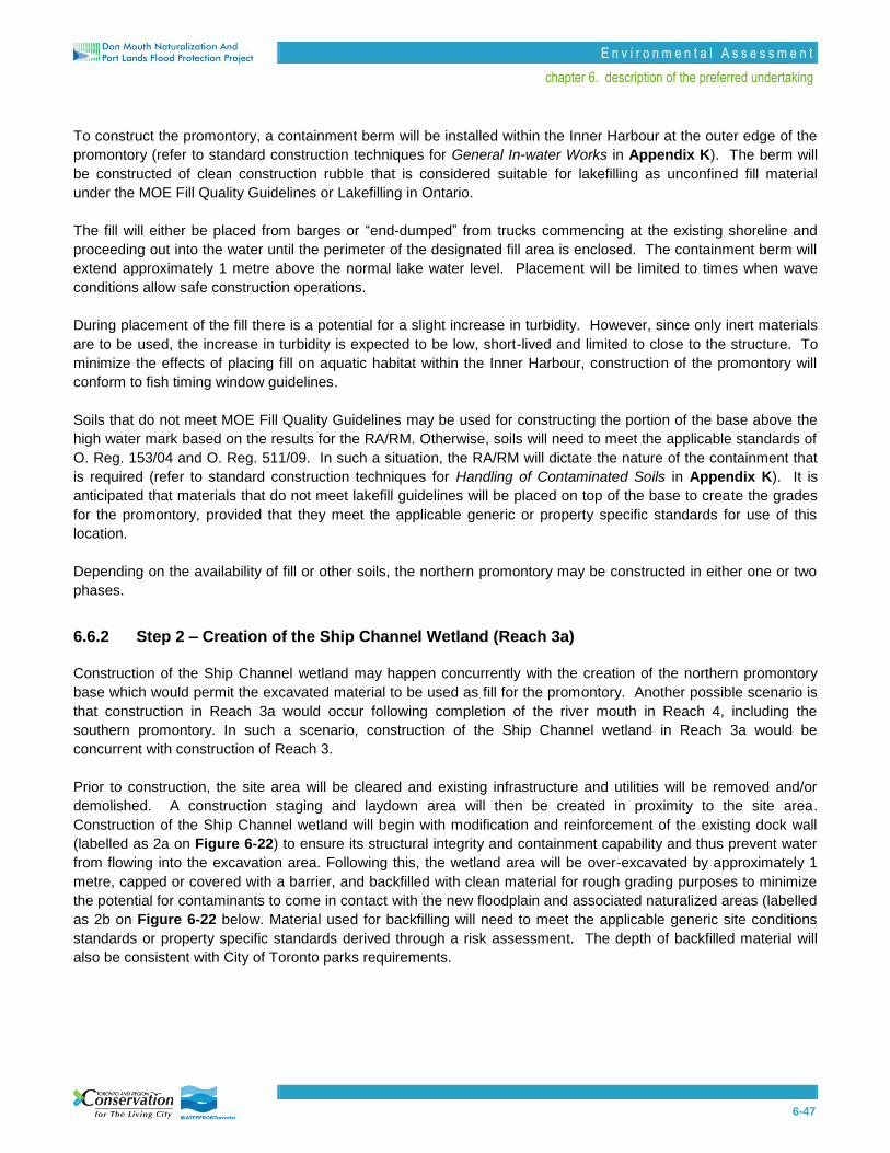
E n v i r o n m e n t a l A s s e s s m e n t
chapter 6. description of the preferred undertaking
6-47
To construct the promontory, a containment berm will be installed within the Inner Harbour at the outer edge of the
promontory (refer to standard construction techniques for General In-water Works in Appendix K). The berm will
be constructed of clean construction rubble that is considered suitable for lakefilling as unconfined fill material
under the MOE Fill Quality Guidelines or Lakefilling in Ontario.
The fill will either be placed from barges or “end-dumped” from trucks commencing at the existing shoreline and
proceeding out into the water until the perimeter of the designated fill area is enclosed. The containment berm will
extend approximately 1 metre above the normal lake water level. Placement will be limited to times when wave
conditions allow safe construction operations.
During placement of the fill there is a potential for a slight increase in turbidity. However, since only inert materials
are to be used, the increase in turbidity is expected to be low, short-lived and limited to close to the structure. To
minimize the effects of placing fill on aquatic habitat within the Inner Harbour, construction of the promontory will
conform to fish timing window guidelines.
Soils that do not meet MOE Fill Quality Guidelines may be used for constructing the portion of the base above the
high water mark based on the results for the RA/RM. Otherwise, soils will need to meet the applicable standards of
O. Reg. 153/04 and O. Reg. 511/09. In such a situation, the RA/RM will dictate the nature of the containment that
is required (refer to standard construction techniques for Handling of Contaminated Soils in Appendix K). It is
anticipated that materials that do not meet lakefill guidelines will be placed on top of the base to create the grades
for the promontory, provided that they meet the applicable generic or property specific standards for use of this
location.
Depending on the availability of fill or other soils, the northern promontory may be constructed in either one or two
phases.
6.6.2 Step 2 – Creation of the Ship Channel Wetland (Reach 3a)
Construction of the Ship Channel wetland may happen concurrently with the creation of the northern promontory
base which would permit the excavated material to be used as fill for the promontory. Another possible scenario is
that construction in Reach 3a would occur following completion of the river mouth in Reach 4, including the
southern promontory. In such a scenario, construction of the Ship Channel wetland in Reach 3a would be
concurrent with construction of Reach 3.
Prior to construction, the site area will be cleared and existing infrastructure and utilities will be removed and/or
demolished. A construction staging and laydown area will then be created in proximity to the site area.
Construction of the Ship Channel wetland will begin with modification and reinforcement of the existing dock wall
(labelled as 2a on Figure 6-22) to ensure its structural integrity and containment capability and thus prevent water
from flowing into the excavation area. Following this, the wetland area will be over-excavated by approximately 1
metre, capped or covered with a barrier, and backfilled with clean material for rough grading purposes to minimize
the potential for contaminants to come in contact with the new floodplain and associated naturalized areas (labelled
as 2b on Figure 6-22 below. Material used for backfilling will need to meet the applicable generic site conditions
standards or property specific standards derived through a risk assessment. The depth of backfilled material will
also be consistent with City of Toronto parks requirements.

6-48
Figure 6-22 Excavation of Ship Channel Wetland (Reach 3a)

E n v i r o n m e n t a l A s s e s s m e n t
chapter 6. description of the preferred undertaking
6-49
The soils removed during excavation will be managed as per Principle 1 in Section 6.5. Valley wall stabilization
will then be installed along the sides of the wetland / spillway as described in Section 6.1.1.1.
Following rough grading, a levee will be constructed at the north end of the wetland and fine grading of the wetland
will occur (labelled as 2c on Figure 6-23 below). The abutments and piers associated with the causeway along
Basin Street will be installed “in the dry”2 (labelled 2d on Figure 6-23 below), as will the rock berm and fish control
structures (elements designed to limit the entrance of carp to the wetland, but to allow other fish species and water
to flow between the wetland and the Ship Channel). Finally the dock wall at the Ship Channel will be partially
removed to connect the wetland to the lake and to allow for establishment of the ecological features (labelled as 2e
on Figure 6-23 below).
2. Construction of the Basin Street causeway is attributable to the Lower Don Lands Infrastructure Municipal Class EA and a future
Environmental Study Report for Phases 3 and 4 of the Municipal Class EA. However, it is expected that the causeway decking will be completed before the dock wall is partially removed.
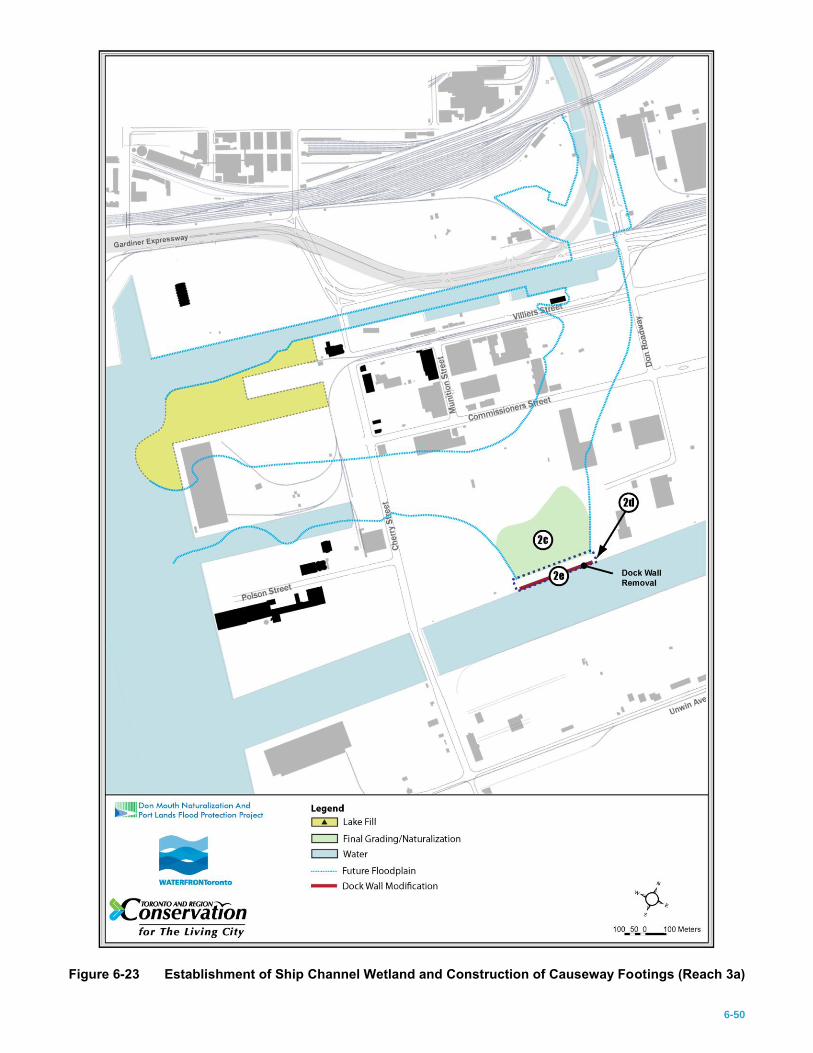
6-50
Figure 6-23 Establishment of Ship Channel Wetland and Construction of Causeway Footings (Reach 3a)
E n v i r o n m e n t a l A s s e s s m e n t
chapter 6. description of the preferred undertaking
6-51
6.6.3 Step 3 – Creation of the River Mouth and Southern Promontory (Reach 4)
6.6.3.1 Lakefilling of the Southern Promontory
The timing of construction in Reach 4 may be advanced to coincide with construction of the northern promontory
during Step 1 or the Ship Channel wetland in Reach 3a, should the land and funding required becomes available.
Construction in Reach 4 will begin with lakefilling activities required to create the base for the southern promontory
and part of the floodplain. Once a construction staging and laydown area has been created, a containment berm
will be constructed in the lake to establish the perimeter of the promontory. Similar to activities in Step 1,
construction of the berm will involve installation of inert rubble or stone and placement or dumping of fill to
approximately 2 metres above normal lake water level. Once the containment berm is established, clean fill or
treated material will be placed within the berm to fill the promontory to the high lake water level (labelled as 3a on
Figure 6-24).

6-52
Figure 6-24 Lakefilling and Excavation of Reach 4

E n v i r o n m e n t a l A s s e s s m e n t
chapter 6. description of the preferred undertaking
6-53
6.6.3.2 Excavation and Rough Grading of the River Mouth
Following creation of the southern promontory, the section of the floodplain and low flow channel in Reach 4 that is
currently dry land will be cleared and existing infrastructure, utilities, and buildings (including foundation
components) will be removed and/or demolished. The existing dock walls will be modified and reinforced to act as
a cofferdam as the area behind the dock walls is over-excavated, capped or covered with a barrier, and backfilled
with clean material and rock revetment for rough grading purposes (labelled as 3b on Figure 6-24). Stabilization
works will then be installed along the edges of the valley system.
Concurrent with rough grading of Reach 4, abutments and piers for the new Cherry Street bridge will be
constructed “in the dry”, along with the installation of the underground utility conduit(s) adjacent to the bridge using
an open cut trench (labelled as 3c on Figure 6-24 – refer to standard construction techniques for Earthworks in
Appendix K). It is anticipated that the existing Cherry Street will need to be realigned slightly to allow for
construction of the bridge footings and other associated activities. Temporary shoring will be installed on the west
side of the existing Cherry Street to allow the road to serve as a plug between Reaches 3 and 4 and to facilitate
public access along the Martin Goodman Trail and through the Port Lands during construction.
6.6.3.3 Lakefilling of the Remainder of the River Mouth
Once excavation and rough grading of the on-land portion of Reach 4 is complete, lakefilling of the remainder of the
valley system, which is currently located within the Inner Harbour and between Polson and Cousins Quays, to
below high lake level can occur (labelled as 3d on Figure 6-24). Following removal of the reinforced dock walls,
rock revetment will be placed “in the wet” to establish rough grading. Material used for backfilling will need to meet
the applicable generic site conditions standards or property specific standards derived through a risk assessment.
6.6.3.4 Fine Grading of the River Mouth
Fine grading of the river mouth will begin with creation of the low flow channel, including the adjacent levee system,
and installation of associated stabilization works “in the wet” (labelled as 3e on Figure 6-25). Ecological features
will be established within the valley system for Reach 4 and will include aquatic, wetland and terrestrial habitat with
planting of appropriate species, in-channel fish habitat structures controls for invasive species, and hydraulic
connections between wetland areas (labelled as 3f on Figure 6-25).

6-54
Figure 6-25 Construction of the Low Flow Channel and Naturalization within Reach 4

E n v i r o n m e n t a l A s s e s s m e n t
chapter 6. description of the preferred undertaking
6-55
6.6.4 Step 4 – Construction of the Remainder of the Valley System (Reaches 2 and 3)
The remainder of the valley system will be built in a similar fashion to Reaches 3a and 4. Prior to construction, the
site area will be cleared and existing infrastructure, utilities, and buildings will be removed and/or demolished. To
ensure that other uses adjacent to or in the vicinity of the future valley system maintain servicing during
construction, existing connections will only be removed once new servicing is provided3.
Starting from the downstream end of Reach 3, the valley system area will be over-excavated, capped or covered
with a barrier, and backfilled with clean material for rough grading purposes (labelled as 4a on Figure 6-26). As
part of rough grading, stabilization features will be installed along the edges of the valley system. Concurrent with
rough grading of Reach 3, the underground utility conduit(s) immediately to the north of Reach 3a will be
constructed “in the dry” (labelled as 4b on Figure 6-26). It is proposed that temporary shoring be installed on both
sides of the existing Commissioners Street alignment so that the road can be left in place as a plug (labelled as 4c
on Figure 6-26).
3. New water and wastewater servicing is associated with the Lower Don Lands Infrastructure Municipal Class EA.
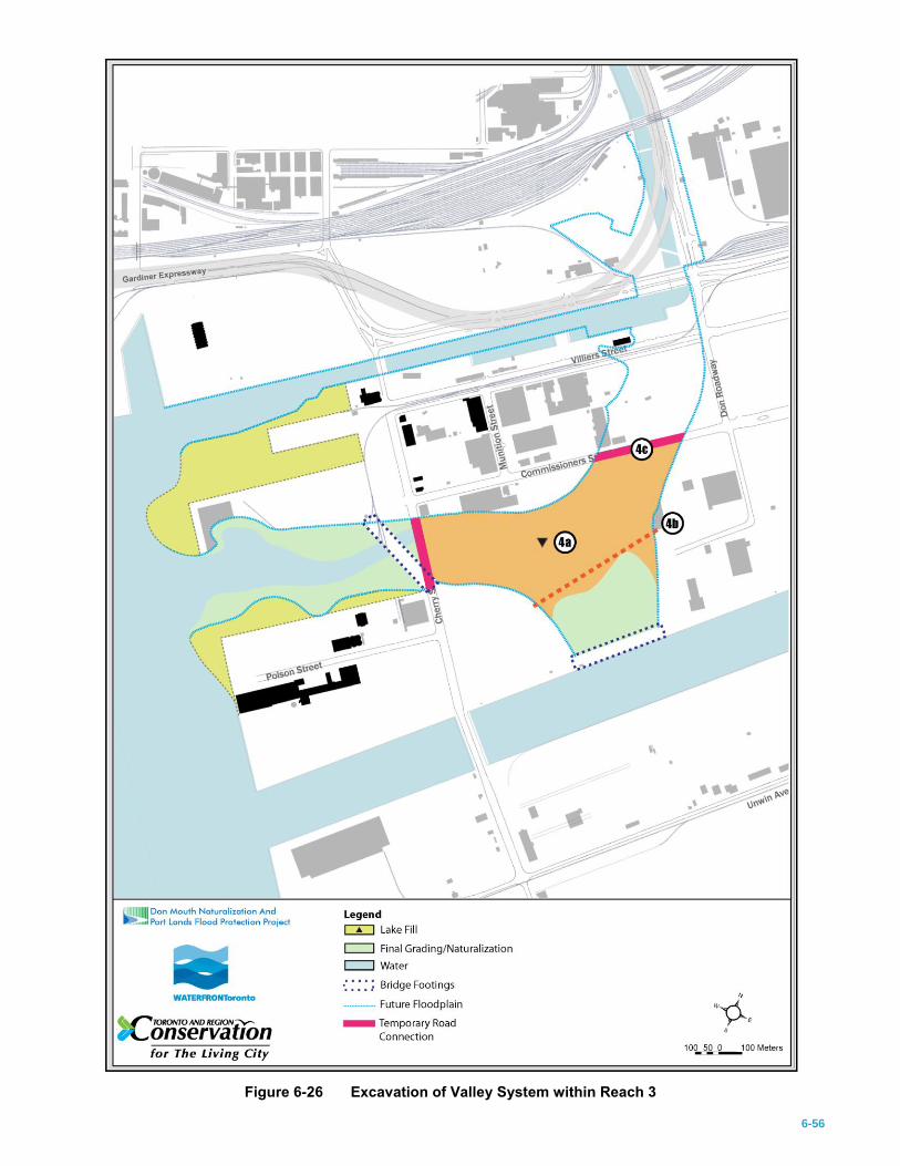
6-56
Figure 6-26 Excavation of Valley System within Reach 3

E n v i r o n m e n t a l A s s e s s m e n t
chapter 6. description of the preferred undertaking
6-57
To support the potential for future establishment of seepage wetlands within the river valley, buried “French drains”
consisting of clean gravel, sand and/or broken concrete may be installed in the appropriate locations. An aquatard
(likely consisting of a clay-rich soil) would be constructed over the “French drains” except at the desired seepage
zone. The “French drains” would not become functional until some point after the green-roof runoff of the future
River Precinct is connected to the upstream end of the “French drains” outside of the valley system.
Fine grading of Reach 3 will include creation of the low flow channel, installation of associated stabilization, and
establishment of ecological features (labelled as 4d on Figure 6-27). During fine grading, slope and soil
stabilization will be occur where necessary. The existing Cherry Street alignment will then be excavated to connect
Reach 3 to the river mouth and to allow lake water into the naturalized system.
Site preparation, excavation and rough grading will be repeated for the upstream section of Reach 3 (upstream of
the existing Commissioners Street alignment) and for Reach 2 (labelled as 4e on Figure 6-27), which will include
construction of abutments, piers, and ice management features for the new Commissioners Street bridge and
installation of the adjacent underground utility conduit(s) “in the dry” (labelled as 4f on Figure 6-27). The existing
dock wall at the east end of the Keating Channel will be left in place to isolate the new valley system and the
current channel until construction is complete.
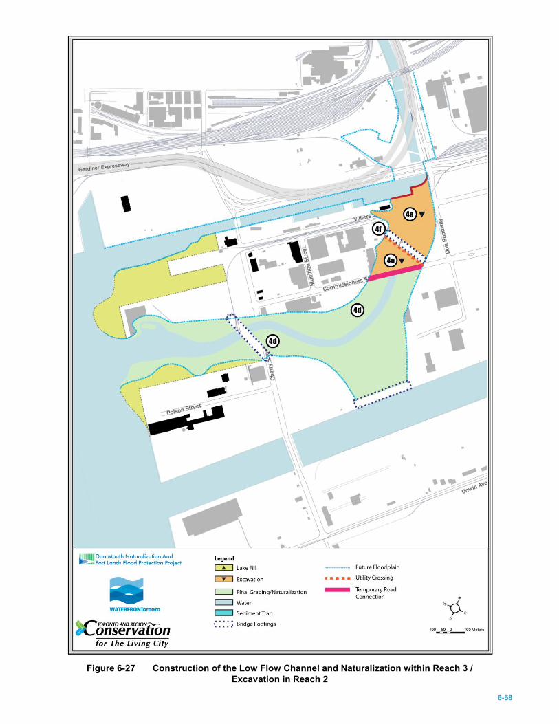
6-58
Figure 6-27 Construction of the Low Flow Channel and Naturalization within Reach 3 /
Excavation in Reach 2
E n v i r o n m e n t a l A s s e s s m e n t
chapter 6. description of the preferred undertaking
6-59
To complete Step 4, fine grading of the remaining section of Reach 3 and all of Reach 2 will occur (labelled as 4g
on Figure 6-28), followed by excavation of the old Commissioners Street to connect to the downstream reaches.
At the end of Step 4, the entire naturalized system within Reaches 2 to 4 will be connected to the lake.

6-60
Figure 6-28 Connection of the New River Mouth to the Lake (Reaches 2, 3 and 4)
E n v i r o n m e n t a l A s s e s s m e n t
chapter 6. description of the preferred undertaking
6-61
6.6.5 Step 5 – Construction of a Sediment and Debris Management Area and Establishment of
Flood Protection Features
This step includes construction of a sediment and debris management area north of Lake Shore Boulevard and
associated features, as well as construction and establishment of various flood protection features in Reaches 1, 2,
and 3. Unlike other steps, this one cannot proceed earlier given the potential impacts of increased flooding by
widening the channel between the CN Rail bridge and Lake Shore Boulevard, which would result in improving
conveyance to the Keating Channel without improving conveyance to the lake.
Prior to construction, the site area will be cleared and most of the existing infrastructure and utilities will be
removed. Certain utilities, such as the Hydro One bridge4 (labelled as 5a on Figure 6-29), and recreational trails,
such as the Don River Bikeway, will be relocated. A construction staging and laydown area, including the service
road connecting Lake Shore Boulevard to the future sediment debris management area, will then be created.
4. At this time, the preferred approach for replacing the existing Hydro One bridge is not known. Should Hydro One decide that its
utilities be buried underneath the channel, additional excavation of the widened channel will need to occur to accommodate the infrastructure.

6-62
Figure 6-29 Construction of the Sediment / Debris Management Area and Flood Protection Features
(Reaches 1, 2 and 3)
E n v i r o n m e n t a l A s s e s s m e n t
chapter 6. description of the preferred undertaking
6-63
6.6.5.1 Construction of the Sediment and Debris Management Area
Construction of the management area in Reach 1 will begin with widening and deepening the existing channel to
create the sediment trap. The sheet pile along the west side of the existing channel will be modified and reinforced
to act as a cofferdam while excavation of the widened channel to the west of the existing channel occurs “in the
dry”. Within the widened channel, the associated portion of the sediment trap will be excavated and a headwall
installed, followed by excavation of the area associated with the barge / boat slip (labelled as 5b on Figure 6-29).
Where possible, construction will be timed to minimize effects on fish and other aquatic species.
Once the widened portion of the channel has been built, the future debris management area adjacent to the new
channel will be excavated for soil management purposes (labelled as 5c on Figure 6-29). As is proposed for the
other reaches, the channel and the debris management area will be over-excavated, capped or covered with a
barrier, and backfilled with clean material. Concrete footings and the platform for the management area will then be
installed “in the dry”. Construction of the management area will take into account the maintenance and storage
shafts for the future CSO tunnels provided that the locations for the shafts and associated above-ground facilities
do not interfere with sediment and debris operational management activities.
A temporary access road will be built to connect the sediment and debris management area to the existing Lake
Shore Boulevard. The road will ultimately be replaced with a permanent road as the Keating Channel Precinct is
developed.
The lengthening of the Lake Shore Boulevard bridge and Harbour Lead bridge from two to five bays, which is
required to provide the necessary flood conveyance, will occur “in the dry” at this time. While this activity is
associated with the Lower Don Lands Infrastructure Municipal Class EA and is not part of this EA, the weir that is
located on the upstream side of the new Lake Shore Boulevard bridge (labelled as 5d on Figure 6-29) is an
element of this EA and will be installed “in the dry” concurrent with the bridge lengthening.
Before the existing portion of the channel is dug down to construct the remainder of the sediment trap, the western
edge of the widened channel will be stabilized using sheetpile or armour stone so that it can function as the primary
conveyance feature during construction. The existing portion of the channel will then be dredged to set the
elevation of the remaining portion of the sediment trap. Once excavation is complete, the sheet pile wall separating
the existing and widened portions of the channel will be removed.
It is proposed that a hydraulic dredge be used to dredge the new sediment trap until the fixed slurry pipe described
in Section 6.1.2.2 is installed.
6.6.5.2 Installation of Additional Flood Protection Features
As described in Section 6.1, there are a number of permanent and temporary flood protection features. These
include regrading of the Don Roadway north of Lake Shore Boulevard and flood protection associated with grading
of the area around the Eastern Avenue underpass of the CN embankment. In addition, the flood protection
landform on the east side of the channel between Lake Shore Boulevard and the CN Rail bridge will be
constructed. The landform may require the removal of 3 storm sewer outfalls (SSOs). If the SSOs cannot be
removed, backflow prevention may need to be installed on the sewer to prevent floodwater from backing up. At this
time, it is proposed that the existing Don Roadway south of Lake Shore Boulevard be reconstructed and raised in
order to contain flooding to the east (labelled as 5e on Figure 6-29). While the Don Roadway is being rebuilt, one
E n v i r o n m e n t a l A s s e s s m e n t
chapter 6. description of the preferred undertaking
6-64
or two fixed slurry pipes5 will be installed along the Don Roadway between Lake Shore Boulevard and to the Ship
Channel and then west along the Basin Street causeway at the downstream end of Reach 3a (labelled as 5f on
Figure 6-29). The slurry pipes will have maintenance access points at regular intervals to allow operators to
remove any blockages that may occur.
Once at the Basin Street causeway, the slurry will enter a floating hydrocyclone to separate sediment from water,
and to segregate the sediment by grain size for transfer onto one of two awaiting barges. Alternatively, the floating
hydrocyclone will be located at the east end of Reach 2a in the Keating Channel with flexible piping extending from
the hydraulic dredge in Reach 1 to the hydrocyclone. Again, water will be separated from the sediment and the
sediments distributed to one of two awaiting barges for disposal or reuse. Alternatively, a similar land-based
dewatering system could be installed along the Don Roadway to manage sediment for use in construction if
appropriate.
To permanently remove flood risk from future development areas, the lands on either side of the river will be
elevated above existing elevations to match the final grades (labelled as 5g on Figure 6-30). The connection
between the Keating Channel and the new river can then be established.
5. A second pipe would provide redundancy to the system to allow operations to continue in the event of a blockage or during the
future replacement period for that infrastructure.

6-65
Figure 6-30 Narrowing of the Keating Channel
E n v i r o n m e n t a l A s s e s s m e n t
chapter 6. description of the preferred undertaking
6-66
6.6.6 Step 6 – Keating Channel (Reach 2a)
This step involves construction works within the Keating Channel, which can proceed only after all flood
conveyance features have been constructed and Reach 1 has been connected to the downstream reaches so as to
avoid exacerbating flooding elsewhere. To begin, the remaining dock wall separating the Keating Channel from the
downstream portion of Reach 2 will be removed (labelled as 6a on Figure 6-30). While this activity can be
undertaken “in the dry” through installation of a cofferdam immediately upstream of the dock wall and associated
dewatering while the dock wall is demolished, it may also occur through the use of industrial underwater welders.
Once the dock wall and cofferdam are removed and the upstream and downstream portions of the new river are
connected, a sideflow weir will be installed in Reach 2a (labelled as 6b on Figure 6-30).
Construction activity in and across the Keating Channel can then proceed. Once the new Cherry Street bridge is
built6, the old Cherry Street bridge will be removed and the Toronto Port Authority (TPA) works yard will be
relocated7. Following these activities, the southern edge of the Keating Channel will be filled in, the entire length of
the channel bottom will be lowered through dredging in order to install rip rap revetment, and the in-channel habitat
structures will be implemented at this site (labelled as 6c on Figure 6-30). Filling in of the Keating Channel will
require dredging of the channel bottom to the desired depth and placement of rock fill along the existing dock walls
to create the revetment. Further, as part of the Lower Don Lands Infrastructure Municipal Class EA activities, in
addition to the new Cherry Street bridge crossing, the Munition Street and Trinity Street bridges will be extended as
additional crossings of the Keating Channel and the Don Valley Trail will serve as a pedestrian crossing (labelled as
6d on Figure 6-30).
6.6.7 Step 7 – Final Grading
The last step of the construction plan involves finalizing the grading on the promontories north and south of the new
river mouth and other naturalized areas, including upland forest areas, adjacent to the valley system.
6. This activity is part of the Lower Don Lands Infrastructure Municipal Class EA.
7. Some function will be moved to the sediment management facility – the other functions will be relocated to a designated site in the Turning Basin of the Ship Channel.