5mp camera with flash instruction manual manuals/ins-15003.pdf · doc # ins-sft-15003 issue date:...
TRANSCRIPT
Doc # INS-SFT-15003 Issue Date: 08/12/2016
Revision: B Page 1 of 30
Prior to Using This Document: Videology reserves the right to modify the information in this
document as necessary and without notice. It is the user’s responsibility to be certain they possess the
most recent version of this document by going to www.videologyinc.com, searching for the model
number, and comparing revision letters on the respective document, located in the document’s footer.
For technical assistance with this product, please contact the supplier from whom the product was
purchased.
Videology Imaging Solutions, Inc. USA Videology Imaging Solutions, B.V. Europe
37M Lark Industrial Parkway Greenville, RI 02828 Tel: 401-949-5332 Fax: 401-949-5276
www.videologyinc.com
Neutronenlaan 4 NL-5405 NH Uden, Netherlands Tel: +31 (0) 413-256261 Fax: +31 (0) 413-251712
www.videology.nl
5MP Camera with Flash
Instruction Manual 24C708AF
SFT-15003 Rev 2.1.0.0 Preliminary
IMAGING SOLUTIONS INC. Original Equipment Manufacturer
Doc # INS-SFT-15003 Issue Date: 08/12/2016
Revision: B Page 2 of 30
License Agreement (Software):
This Agreement states the terms and conditions upon which Videology Imaging Solutions, Inc. USA and
Videology Imaging Solutions, B.V. Europe (hereafter referred to as "Videology®") offer to license to you the
software together with all related documentation and accompanying items including, but not limited to,
the executable programs, drivers, libraries, and data files associated with such software.
The Software is licensed, not sold, to you for use only under the terms of this Agreement.
Videology grants to you, the purchaser, the right to use all or a portion of this Software provided that the
Software is used only in conjunction with Videology's family of products.
In using the Software you agree not to:
Decompile, disassemble, reverse engineer, or otherwise attempt to derive the source code for any
Product (except to the extent applicable laws specifically prohibit such restriction);
Remove or obscure any trademark or copyright notices.
Limited Warranty (Hardware and Software):
ANY USE OF THE SOFTWARE OR HARDWARE IS AT YOUR OWN RISK. THE SOFTWARE IS PROVIDED FOR
USE ONLY WITH VIDEOLOGY'S HARDWARE. THE SOFTWARE IS PROVIDED FOR USE "AS IS" WITHOUT
WARRANTY OF ANY KIND, TO THE MAXIMUM EXTENT PERMITTED BY LAW, VIDEOLOGY DISCLAIMS ALL
WARRANTIES OF ANY KIND, EITHER EXPRESS OR IMPLIED, INCLUDING, WITHOUT LIMITATION, IMPLIED
WARRANTIES OR CONDITIONS OF MERCHANTABILITY, QUALITY AND FITNESS FOR A PARTICULAR
APPLICATION OR PURPOSE. VIDEOLOGY IS NOT OBLIGATED TO PROVIDE ANY UPDATES OR UPGRADES
TO THE SOFTWARE OR ANY RELATED HARDWARE.
Limited Liability (Hardware and Software):
In no event shall Videology or its Licensor's be liable for any damages whatsoever (including, without
limitation, incidental, direct, indirect, special or consequential damages, damages for loss of business
profits, business interruption, loss of business information, or other pecuniary loss) arising out of the use
or inability to use this Software or related Hardware, including, but not limited to, any of Videology's
family of products.
Doc # INS-SFT-15003 Issue Date: 08/12/2016
Revision: B Page 3 of 30
Table of Contents
1. Document History .................................................................................................................... 4 2. About the Camera ................................................................................................................... 4 3. Specifications .......................................................................................................................... 4
3.1. Flash Support ................................................................................................................... 5 3.2. Still Image Capture ........................................................................................................... 5 3.3. Camera / Flash ................................................................................................................. 5
4. Viewer Installation ................................................................................................................... 6 5. VIS Viewer ........................................................................................................................... 10
5.1. Devices ......................................................................................................................... 10 5.2. Options.......................................................................................................................... 12
5.2.1. Video Renderer ........................................................................................................ 12 5.2.2. Quality .................................................................................................................... 13 5.2.3. Direct Draw ............................................................................................................. 13 5.2.4. Performance ............................................................................................................ 14
5.3. Video Capture Filter ........................................................................................................ 15 5.3.1. Video Proc. Amp ...................................................................................................... 15
5.4. Video Capture Pin ........................................................................................................... 16 5.4.1. Stream Format ........................................................................................................ 16
5.5. Still Capture Pin .............................................................................................................. 17 5.6. Current Settings ............................................................................................................. 18 5.7. Capture ......................................................................................................................... 19
5.7.1. Get Still (Enter) ....................................................................................................... 19 5.7.2. Still File Path ........................................................................................................... 19
5.8. Focus ............................................................................................................................ 21 5.8.1. Trigger AutoFocus .................................................................................................... 21
5.9. UVC Extension ................................................................................................................ 22 5.9.1. AF Status ................................................................................................................ 22 5.9.2. AF Trigger ............................................................................................................... 23 5.9.3. Flash Control ........................................................................................................... 24 5.9.4. Debug Control ......................................................................................................... 24
5.10. Help ........................................................................................................................... 26 6. TWAIN Installation ................................................................................................................. 27 7. Using the TWAIN Interface ..................................................................................................... 28
7.1. ZOOM FEATURE .............................................................................................................. 28 7.2. Mode of operation ........................................................................................................... 28
7.2.1. Preview mode .......................................................................................................... 28 8. Contact Information ............................................................................................................... 30
Doc # INS-SFT-15003 Issue Date: 08/12/2016
Revision: B Page 4 of 30
1. Document History
2. About the Camera
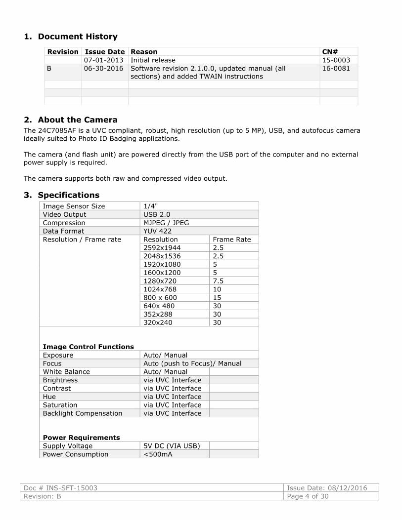
The 24C7085AF is a UVC compliant, robust, high resolution (up to 5 MP), USB, and autofocus camera
ideally suited to Photo ID Badging applications.
The camera (and flash unit) are powered directly from the USB port of the computer and no external
power supply is required.
The camera supports both raw and compressed video output.
3. Specifications
Image Sensor Size 1/4"
Video Output USB 2.0
Compression MJPEG / JPEG
Data Format YUV 422
Resolution / Frame rate Resolution Frame Rate
2592x1944 2.5
2048x1536 2.5
1920x1080 5
1600x1200 5
1280x720 7.5
1024x768 10
800 x 600 15
640x 480 30
352x288 30
320x240 30
Image Control Functions
Exposure Auto/ Manual
Focus Auto (push to Focus)/ Manual
White Balance Auto/ Manual
Brightness via UVC Interface
Contrast via UVC Interface
Hue via UVC Interface
Saturation via UVC Interface
Backlight Compensation via UVC Interface
Power Requirements
Supply Voltage 5V DC (VIA USB)
Power Consumption <500mA
Revision Issue Date Reason CN#
07-01-2013 Initial release 15-0003
B 06-30-2016 Software revision 2.1.0.0, updated manual (all
sections) and added TWAIN instructions
16-0081
Doc # INS-SFT-15003 Issue Date: 08/12/2016
Revision: B Page 5 of 30
3.1. Flash Support
The camera supports one or two Videology LED Flash units.
The flash units are powered from the USB camera
3.2. Still Image Capture
The camera supports a single image "snapshot" mode with optional JPEG compression.
The resolution of the still image is user definable.
3.3. Camera / Flash
The camera is fully UVC compliant and all basic camera controls can be accessed via the standard UVC
command protocol.
The 24C708AF camera, includes an internal processor that automatically detects when a snapshot
command has been issued, and triggers the flash at the appropriate time.
Some applications however do not issue a snapshot command to the camera, and in this case, the
application needs to be modified to include the necessary flash control commands.
The full capabilities of the camera can be demonstrated using the simple viewer application provided.
Doc # INS-SFT-15003 Issue Date: 08/12/2016
Revision: B Page 6 of 30
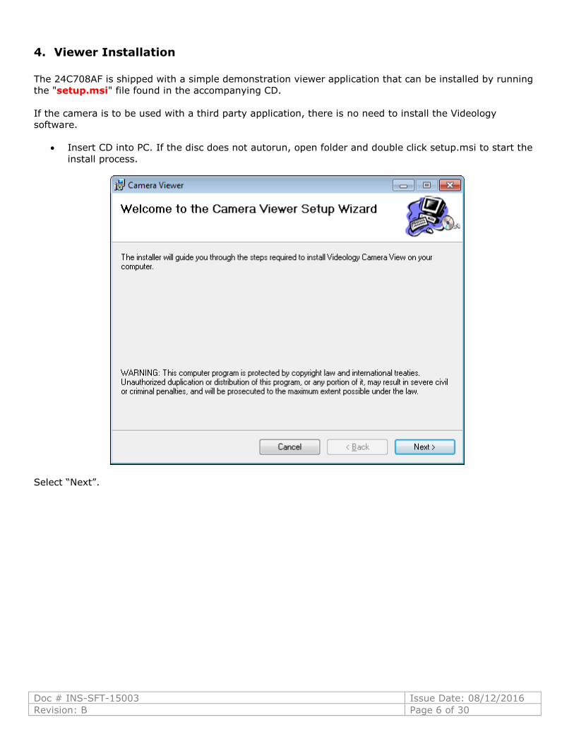
4. Viewer Installation
The 24C708AF is shipped with a simple demonstration viewer application that can be installed by running
the "setup.msi" file found in the accompanying CD.
If the camera is to be used with a third party application, there is no need to install the Videology
software.
Insert CD into PC. If the disc does not autorun, open folder and double click setup.msi to start the
install process.
Select “Next”.
Doc # INS-SFT-15003 Issue Date: 08/12/2016
Revision: B Page 7 of 30
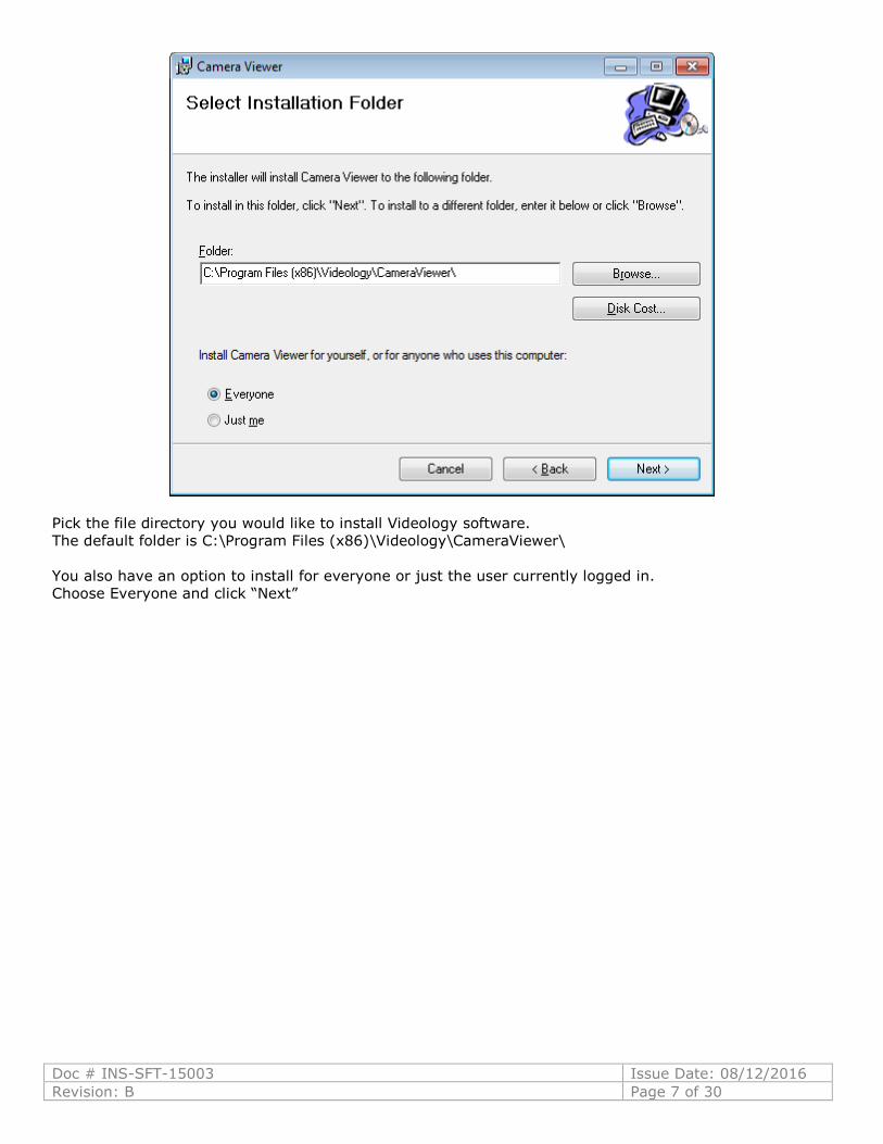
Pick the file directory you would like to install Videology software.
The default folder is C:\Program Files (x86)\Videology\CameraViewer\
You also have an option to install for everyone or just the user currently logged in.
Choose Everyone and click “Next”
Doc # INS-SFT-15003 Issue Date: 08/12/2016
Revision: B Page 8 of 30
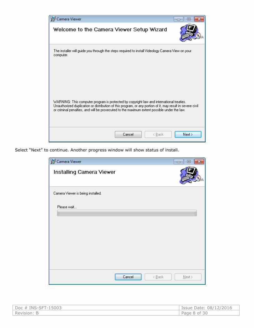
Select “Next” to continue. Another progress window will show status of install.
Doc # INS-SFT-15003 Issue Date: 08/12/2016
Revision: B Page 9 of 30
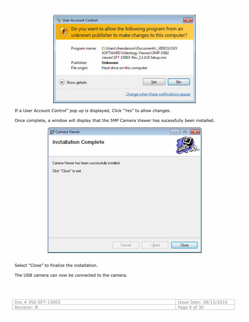
If a User Account Control” pop up is displayed, Click “Yes” to allow changes.
Once complete, a window will display that the 5MP Camera Viewer has sucessfully been installed.
Select “Close” to finalize the installation.
The USB camera can now be connected to the camera.
Doc # INS-SFT-15003 Issue Date: 08/12/2016
Revision: B Page 10 of 30
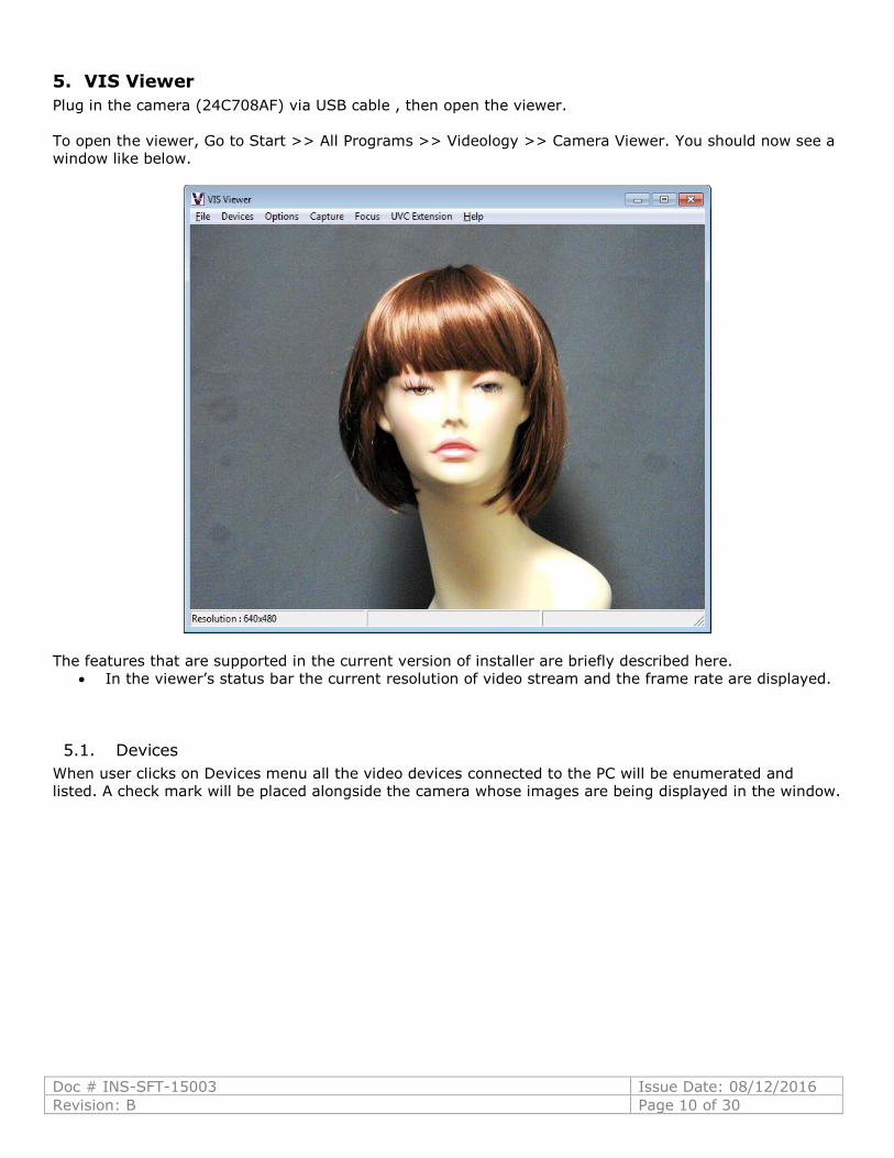
5. VIS Viewer
Plug in the camera (24C708AF) via USB cable , then open the viewer.
To open the viewer, Go to Start >> All Programs >> Videology >> Camera Viewer. You should now see a
window like below.
The features that are supported in the current version of installer are briefly described here.
In the viewer’s status bar the current resolution of video stream and the frame rate are displayed.
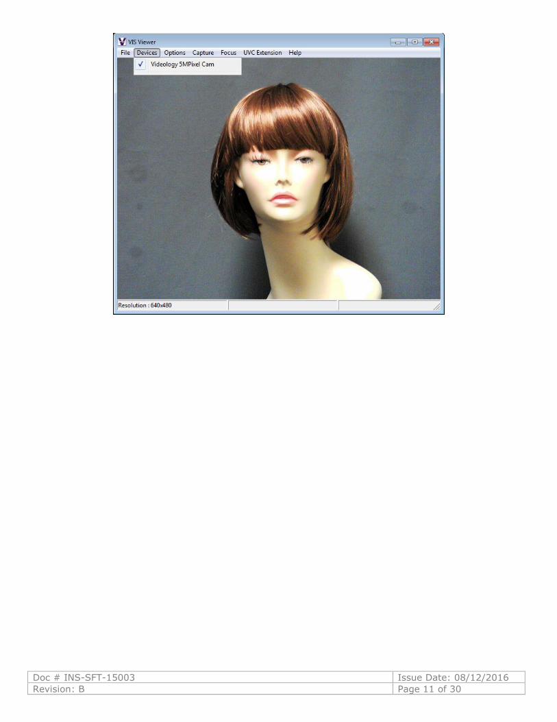
5.1. Devices
When user clicks on Devices menu all the video devices connected to the PC will be enumerated and
listed. A check mark will be placed alongside the camera whose images are being displayed in the window.
Doc # INS-SFT-15003 Issue Date: 08/12/2016
Revision: B Page 11 of 30
Doc # INS-SFT-15003 Issue Date: 08/12/2016
Revision: B Page 12 of 30
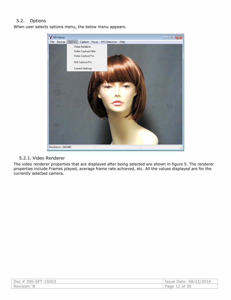
5.2. Options
When user selects options menu, the below menu appears.
5.2.1. Video Renderer
The video renderer properties that are displayed after being selected are shown in figure 5. The renderer
properties include Frames played, average frame rate achieved, etc. All the values displayed are for the
currently selected camera.
Doc # INS-SFT-15003 Issue Date: 08/12/2016
Revision: B Page 13 of 30
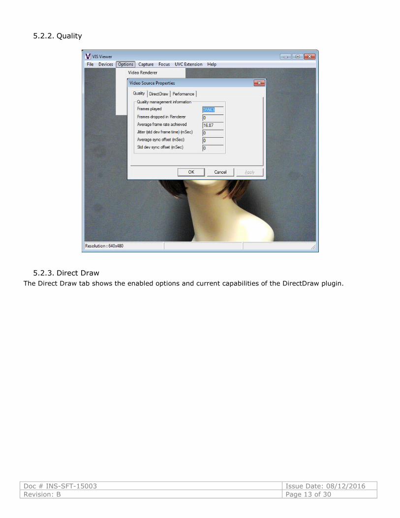
5.2.2. Quality
5.2.3. Direct Draw
The Direct Draw tab shows the enabled options and current capabilities of the DirectDraw plugin.
Doc # INS-SFT-15003 Issue Date: 08/12/2016
Revision: B Page 14 of 30
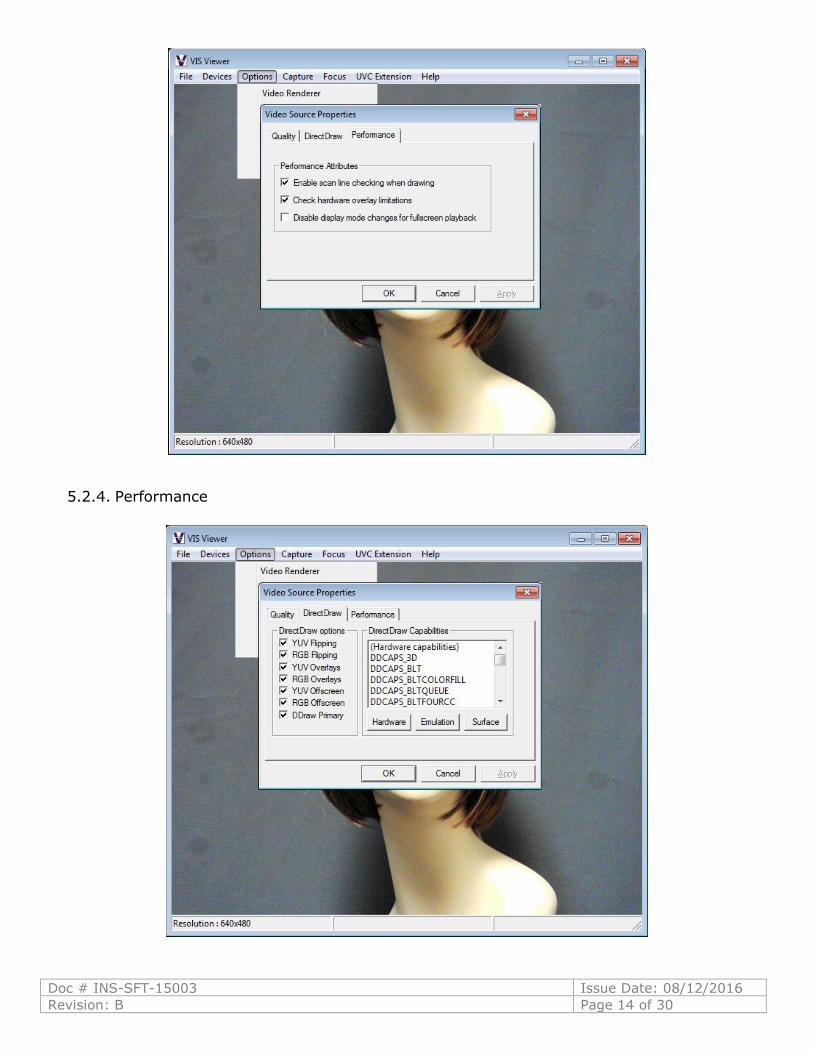
5.2.4. Performance

Doc # INS-SFT-15003 Issue Date: 08/12/2016
Revision: B Page 15 of 30
5.3. Video Capture Filter
5.3.1. Video Proc. Amp
On selecting Video Capture Filter, a dialog will be launched which displays 2 kinds of video capture filter
properties.
a) Video Proc Amp Settings
b) Camera Control Settings
a) Video Proc Amp Settings
The user can adjust the Video proc amp settings in the dialog. Only sliders whose labels are not
grayed out can be configured. The user can move the slider and configure the preview settings
according to their needs.
The value being set will be displayed in the text box associated with the slider. As soon as the
slider is moved to configure the values, the preview’s property will instantly change, Clicking Apply
button saves changes until the next time the dialog is opened.
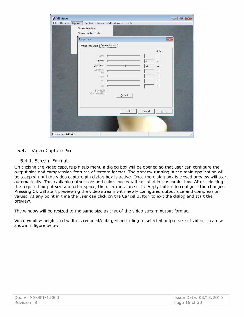
b) Camera Control
To configure the camera control settings of the video capture filter the user can click on the
Camera Control tab. Once again slider control will allow the user to configure the camera settings
according to their need.
Doc # INS-SFT-15003 Issue Date: 08/12/2016
Revision: B Page 16 of 30
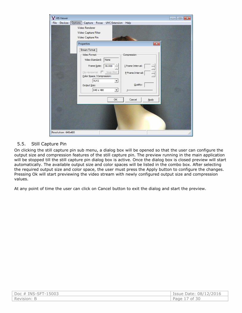
5.4. Video Capture Pin
5.4.1. Stream Format
On clicking the video capture pin sub menu a dialog box will be opened so that user can configure the
output size and compression features of stream format. The preview running in the main application will
be stopped until the video capture pin dialog box is active. Once the dialog box is closed preview will start
automatically. The available output size and color spaces will be listed in the combo box. After selecting
the required output size and color space, the user must press the Apply button to configure the changes.
Pressing Ok will start previewing the video stream with newly configured output size and compression
values. At any point in time the user can click on the Cancel button to exit the dialog and start the
preview.
The window will be resized to the same size as that of the video stream output format.
Video window height and width is reduced/enlarged according to selected output size of video stream as
shown in figure below.
Doc # INS-SFT-15003 Issue Date: 08/12/2016
Revision: B Page 17 of 30
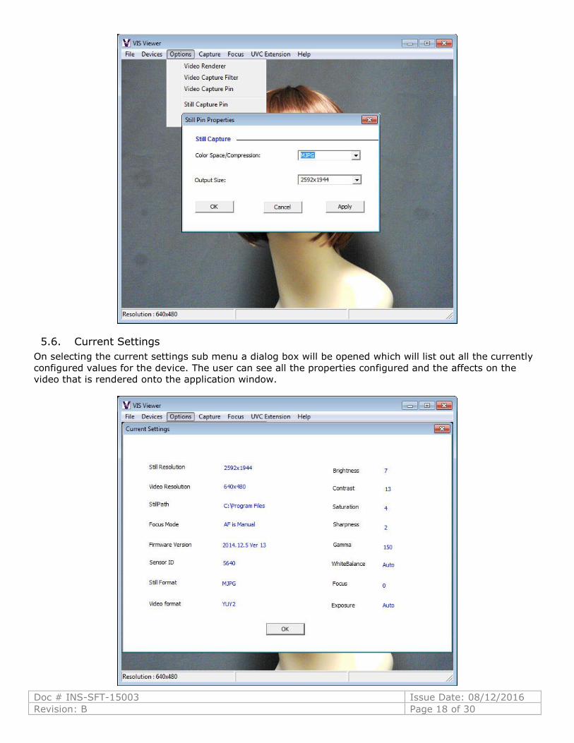
5.5. Still Capture Pin
On clicking the still capture pin sub menu, a dialog box will be opened so that the user can configure the
output size and compression features of the still capture pin. The preview running in the main application
will be stopped till the still capture pin dialog box is active. Once the dialog box is closed preview will start
automatically. The available output size and color spaces will be listed in the combo box. After selecting
the required output size and color space, the user must press the Apply button to configure the changes.
Pressing Ok will start previewing the video stream with newly configured output size and compression
values.
At any point of time the user can click on Cancel button to exit the dialog and start the preview.
Doc # INS-SFT-15003 Issue Date: 08/12/2016
Revision: B Page 18 of 30
5.6. Current Settings
On selecting the current settings sub menu a dialog box will be opened which will list out all the currently
configured values for the device. The user can see all the properties configured and the affects on the
video that is rendered onto the application window.
Doc # INS-SFT-15003 Issue Date: 08/12/2016
Revision: B Page 19 of 30
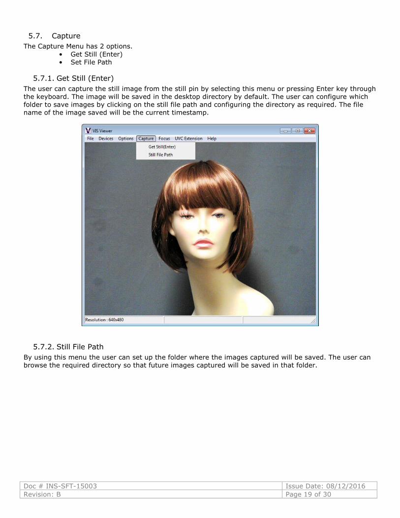
5.7. Capture
The Capture Menu has 2 options.
• Get Still (Enter)
• Set File Path
5.7.1. Get Still (Enter)
The user can capture the still image from the still pin by selecting this menu or pressing Enter key through
the keyboard. The image will be saved in the desktop directory by default. The user can configure which
folder to save images by clicking on the still file path and configuring the directory as required. The file
name of the image saved will be the current timestamp.
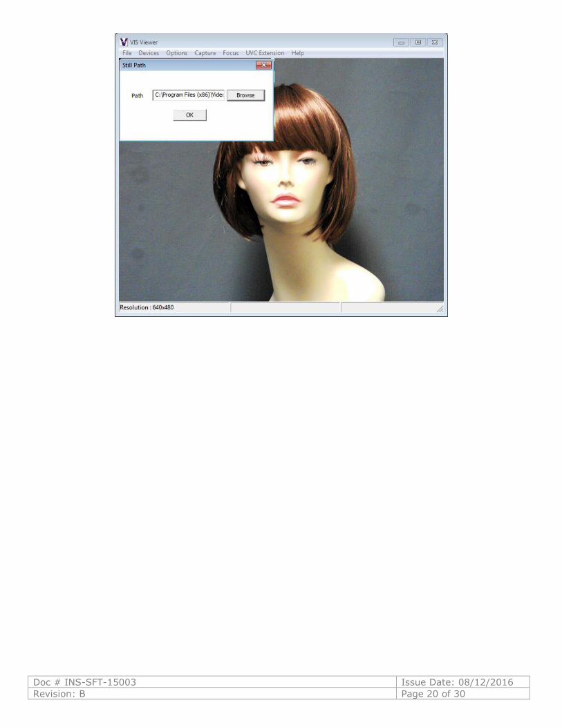
5.7.2. Still File Path
By using this menu the user can set up the folder where the images captured will be saved. The user can
browse the required directory so that future images captured will be saved in that folder.
Doc # INS-SFT-15003 Issue Date: 08/12/2016
Revision: B Page 20 of 30
Doc # INS-SFT-15003 Issue Date: 08/12/2016
Revision: B Page 21 of 30
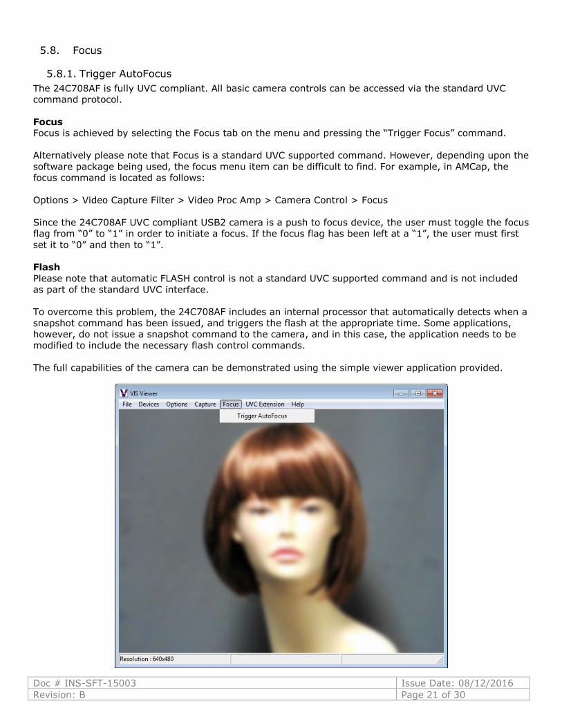
5.8. Focus
5.8.1. Trigger AutoFocus
The 24C708AF is fully UVC compliant. All basic camera controls can be accessed via the standard UVC
command protocol.
Focus
Focus is achieved by selecting the Focus tab on the menu and pressing the “Trigger Focus” command.
Alternatively please note that Focus is a standard UVC supported command. However, depending upon the
software package being used, the focus menu item can be difficult to find. For example, in AMCap, the
focus command is located as follows:
Options > Video Capture Filter > Video Proc Amp > Camera Control > Focus
Since the 24C708AF UVC compliant USB2 camera is a push to focus device, the user must toggle the focus
flag from “0” to “1” in order to initiate a focus. If the focus flag has been left at a “1”, the user must first
set it to “0” and then to “1”.
Flash
Please note that automatic FLASH control is not a standard UVC supported command and is not included
as part of the standard UVC interface.
To overcome this problem, the 24C708AF includes an internal processor that automatically detects when a
snapshot command has been issued, and triggers the flash at the appropriate time. Some applications,
however, do not issue a snapshot command to the camera, and in this case, the application needs to be
modified to include the necessary flash control commands.
The full capabilities of the camera can be demonstrated using the simple viewer application provided.

Doc # INS-SFT-15003 Issue Date: 08/12/2016
Revision: B Page 22 of 30
5.9. UVC Extension
On selecting the UVC Extension menu, the UVC Extension Control dialog box will open. The UVC Extension
library has the features mentioned below:
• Auto Focus Status
• Auto Focus Trigger
• Focus Mode
• Update GPI Status
• Set / Clear GPO’s
• Get Sensor ID
• Get Firmware Version
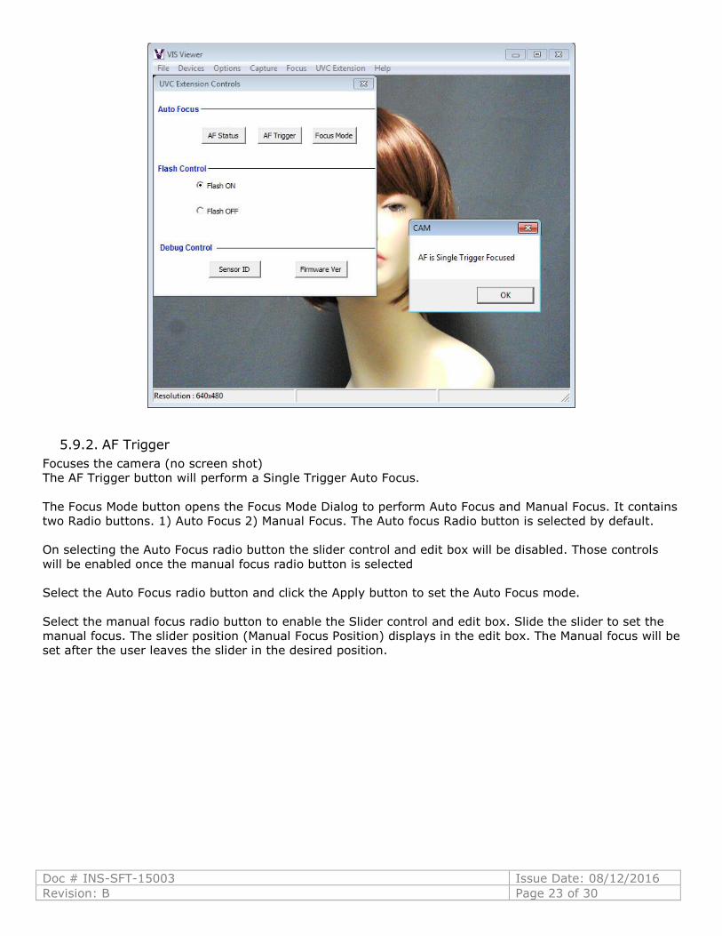
5.9.1. AF Status
The AF Status button shows the current auto focus status.
The possible focus status is shown below.
• AF is Manual
• AF is Single Trigger Focusing
• AF is Single Trigger Focused
Doc # INS-SFT-15003 Issue Date: 08/12/2016
Revision: B Page 23 of 30
5.9.2. AF Trigger
Focuses the camera (no screen shot)
The AF Trigger button will perform a Single Trigger Auto Focus.
The Focus Mode button opens the Focus Mode Dialog to perform Auto Focus and Manual Focus. It contains
two Radio buttons. 1) Auto Focus 2) Manual Focus. The Auto focus Radio button is selected by default.
On selecting the Auto Focus radio button the slider control and edit box will be disabled. Those controls
will be enabled once the manual focus radio button is selected
Select the Auto Focus radio button and click the Apply button to set the Auto Focus mode.
Select the manual focus radio button to enable the Slider control and edit box. Slide the slider to set the
manual focus. The slider position (Manual Focus Position) displays in the edit box. The Manual focus will be
set after the user leaves the slider in the desired position.

Doc # INS-SFT-15003 Issue Date: 08/12/2016
Revision: B Page 24 of 30
5.9.3. Flash Control
Flash Control command is not configured with this model.
5.9.4. Debug Control
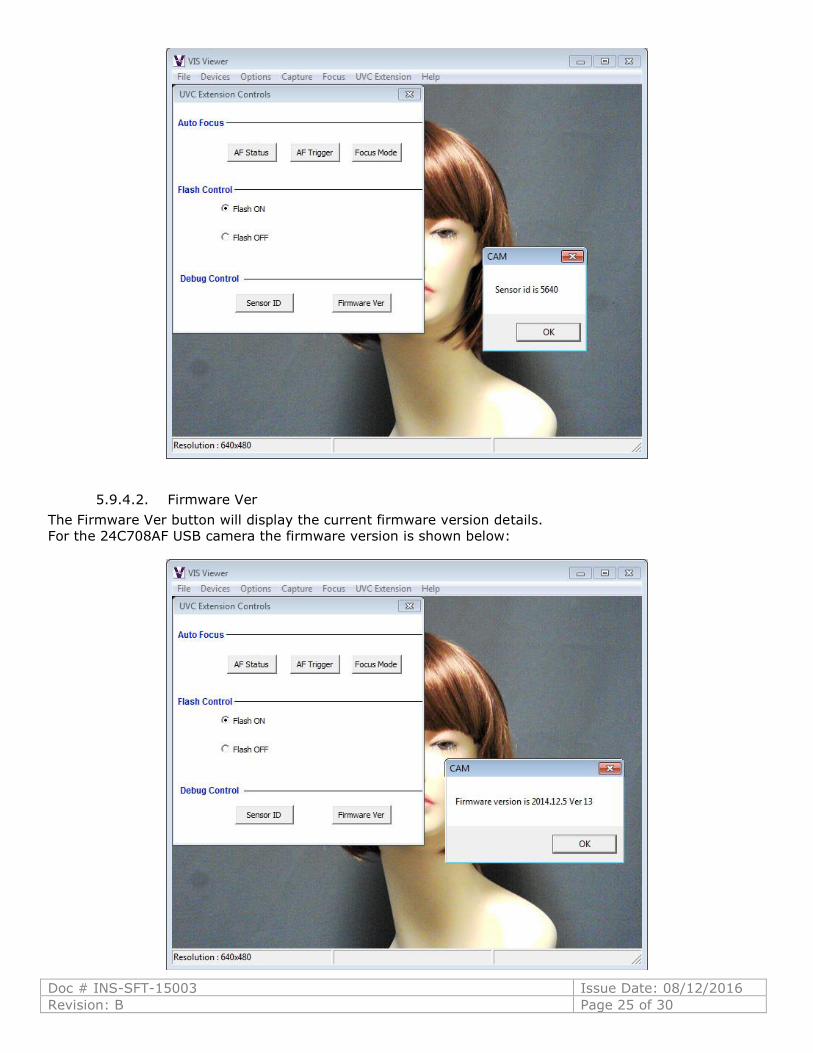
5.9.4.1. Sensor ID
The Sensor ID button will display the current sensor id details.
For the 24C708AF USB camera the id is shown below:
Doc # INS-SFT-15003 Issue Date: 08/12/2016
Revision: B Page 25 of 30
5.9.4.2. Firmware Ver
The Firmware Ver button will display the current firmware version details.
For the 24C708AF USB camera the firmware version is shown below:
Doc # INS-SFT-15003 Issue Date: 08/12/2016
Revision: B Page 26 of 30
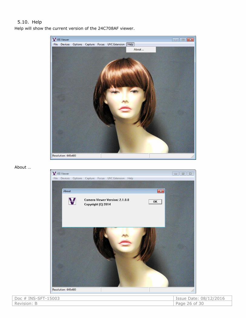
5.10. Help
Help will show the current version of the 24C708AF viewer.
About …
Doc # INS-SFT-15003 Issue Date: 08/12/2016
Revision: B Page 27 of 30
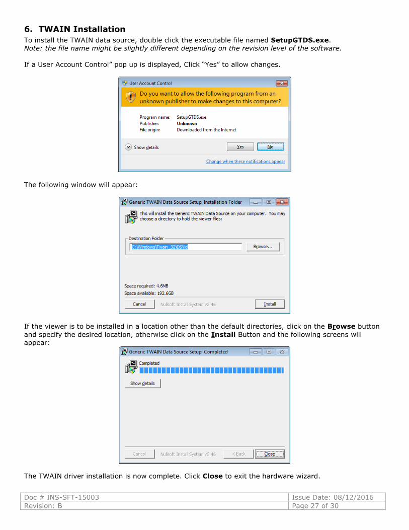
6. TWAIN Installation
To install the TWAIN data source, double click the executable file named SetupGTDS.exe.
Note: the file name might be slightly different depending on the revision level of the software.
If a User Account Control” pop up is displayed, Click “Yes” to allow changes.
The following window will appear:
If the viewer is to be installed in a location other than the default directories, click on the Browse button
and specify the desired location, otherwise click on the Install Button and the following screens will
appear:
The TWAIN driver installation is now complete. Click Close to exit the hardware wizard.
Doc # INS-SFT-15003 Issue Date: 08/12/2016
Revision: B Page 28 of 30
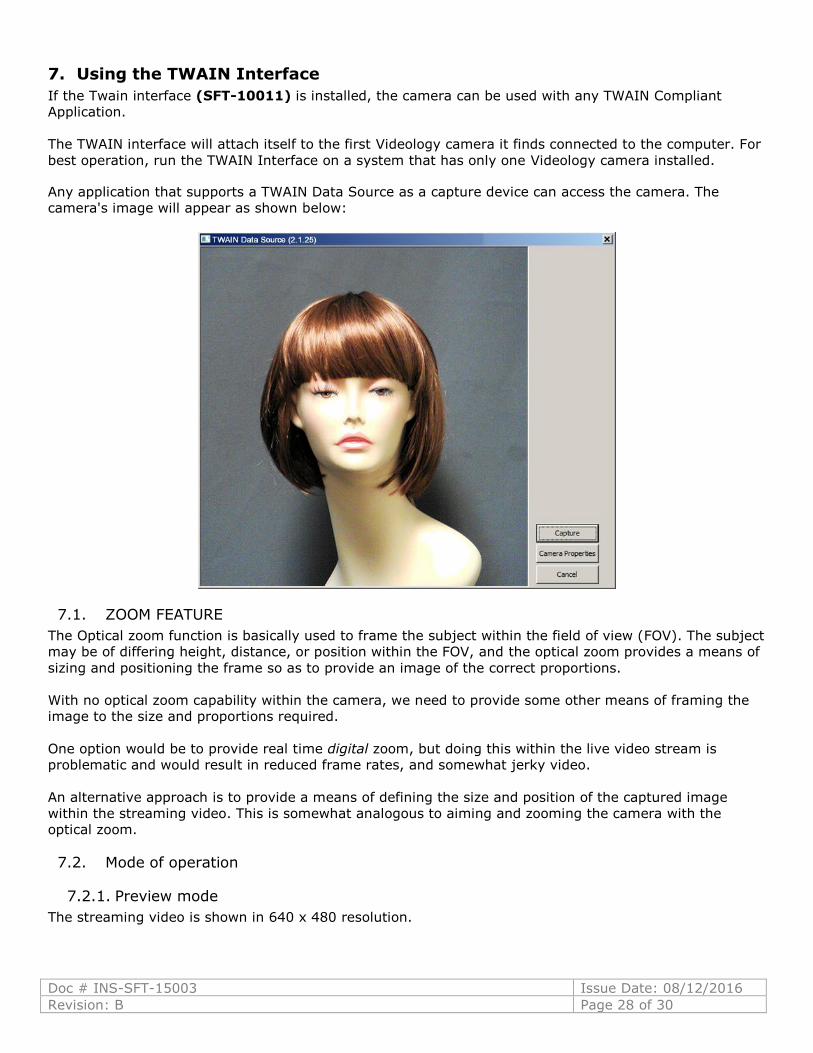
7. Using the TWAIN Interface
If the Twain interface (SFT-10011) is installed, the camera can be used with any TWAIN Compliant
Application.
The TWAIN interface will attach itself to the first Videology camera it finds connected to the computer. For
best operation, run the TWAIN Interface on a system that has only one Videology camera installed.
Any application that supports a TWAIN Data Source as a capture device can access the camera. The
camera's image will appear as shown below:
7.1. ZOOM FEATURE
The Optical zoom function is basically used to frame the subject within the field of view (FOV). The subject
may be of differing height, distance, or position within the FOV, and the optical zoom provides a means of
sizing and positioning the frame so as to provide an image of the correct proportions.
With no optical zoom capability within the camera, we need to provide some other means of framing the
image to the size and proportions required.
One option would be to provide real time digital zoom, but doing this within the live video stream is
problematic and would result in reduced frame rates, and somewhat jerky video.
An alternative approach is to provide a means of defining the size and position of the captured image
within the streaming video. This is somewhat analogous to aiming and zooming the camera with the
optical zoom.
7.2. Mode of operation
7.2.1. Preview mode
The streaming video is shown in 640 x 480 resolution.
Doc # INS-SFT-15003 Issue Date: 08/12/2016
Revision: B Page 29 of 30
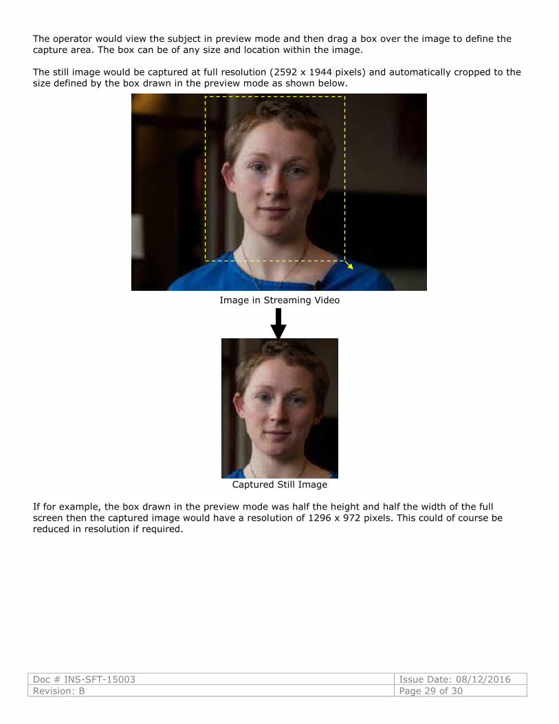
The operator would view the subject in preview mode and then drag a box over the image to define the
capture area. The box can be of any size and location within the image.
The still image would be captured at full resolution (2592 x 1944 pixels) and automatically cropped to the
size defined by the box drawn in the preview mode as shown below.
Image in Streaming Video
Captured Still Image
If for example, the box drawn in the preview mode was half the height and half the width of the full
screen then the captured image would have a resolution of 1296 x 972 pixels. This could of course be
reduced in resolution if required.

Doc # INS-SFT-15003 Issue Date: 08/12/2016
Revision: B Page 30 of 30
8. Contact Information
For technical assistance with this product, please contact the supplier from whom the product
was purchased.
For OEM inquiries, contact Videology® Imaging Solutions:
Americas, Middle East, Far East & Australia: Europe & N. Eurasia:
Videology® Imaging Solutions Inc.
37M Lark Industrial Parkway
Greenville, RI 02828
USA
Tel: (401) 949-5332
Fax: (401) 949-5276
Videology® Imaging Solutions Europe B.V.
Neutronenlaan 4
5405 NH Uden
The Netherlands
Tel: +31 (0) 413-256261
Fax: +31 (0) 413-251712
Please visit our website: videologyinc.com
VIDEOLOGY IMAGING SOLUTIONS is an ISO 9001 registered video camera developer and
manufacturer serving industrial, machine vision, biometric, security, and specialty OEM markets.
Videology designs, develops, manufactures, and distributes video, image acquisition, and display
technologies and products to OEMs worldwide.