5g implementation guidelines: nsa option 3
TRANSCRIPT
5G Implementation Guidelines:
NSA Option 3 February 2020
5G Implementation Guidelines
2
About the GSMA
The GSMA represents the interests of mobile operators
worldwide, uniting nearly 750 operators with almost 300
companies in the broader mobile ecosystem, including
handset and device makers, software companies,
equipment providers and internet companies, as well as
organisations in adjacent industry sectors. The GSMA also
produces industry-leading events such as Mobile World
Congress (Barcelona, Shanghai and Los Angeles) and the
Mobile 360 Series of conferences.
For more information, please visit the GSMA corporate
website at www.gsma.com. Follow the GSMA on Twitter:
@GSMA.
Future Networks Programme
The GSMA’s Future Networks is designed to help operators
and the wider mobile industry to deliver All-IP networks so
that everyone benefits regardless of where their starting
point might be on the journey.
The programme has three key work-streams focused on:
The development and deployment of IP services, The
evolution of the 4G networks in widespread use today, The
5G Journey developing the next generation of mobile
technologies and service.
For more information, please visit the Future Networks
website at: www.gsma.com/futurenetworks
Document Editor
Sandra Ondrusova, CK Hutchison
Dongwook Kim, GSMA
5G Implementation Guidelines
3
OverviewIntroduction
5G is becoming a reality as early adopters
have already commercialized data-oriented 5G
networks in 2018 and launched consumer
mobile 5G in 2019. Whilst early adopters do
not necessarily require guidance, there are still
majority of the operator community that are yet
to launch commercial 5G services. This
document intends to provide a checklist for
operators that are planning to launch 5G
networks in NSA (non-standalone) Option 3
configuration.
Scope
This document provides technological,
spectrum and regulatory considerations in the
deployment.
This version of the document currently
provides detailed guidelines for implementation
of 5G using Option 3, reflecting the initial
launch strategy being adopted by multiple
operators. However, as described in “GSMA
Operator Requirements for 5G Core
Connectivity Options” there is a need for the
industry ecosystem to support all of the 5G
core connectivity options (namely Option 2,
Option 4, Option 5 and Option 7) in addition to
Option 3. As a result, this document will be
updated to provide guidelines for all 5G
deployment options. Implementation Guideline
for Option 2 has been completed and available
publicly.
Note: The topics listed in this document is not
exhaustive and is open to
suggestion/contribution by any company.
Please contact [email protected]
Acknowledgements
Special thanks to the following GSMA
Checklist for Non-Standalone 5G Deployment
taskforce members for their contribution and
review of this document:
• AT&T Mobility
• EE Limited
• Ericsson
• Huawei Technologies Co. Ltd.
• Hutchison 3G UK Limited
• KDDI
• LG Electronics Inc.
• MediaTek Inc.
• Nokia
• NTT DOCOMO
• Softbank Corp.
• Syniverse Technologies, Inc.
• Telecom Italia SpA
• Telefónica S.A.
• Telia Finland Oyj
• United States Cellular Corporation
• Utimaco TS GmbH
• Verizon Wireless
• Vodafone Group
• ZTE Corporation
5G Implementation Guidelines
4
Abbreviations
Term Description
2D 2 Dimensions
3D 3 Dimensions
3GPP 3rd Generation Partnership Project
5GC 5G Core
AMBR Aggregate Maximum Bit Rate
AMF Access and Mobility Management
Function
AN Access Network
APN Access Point Name
AR Augmented Reality
ARD Access Restriction Data
AVP Attribute-Value pairs
BEREC The Body of European Regulators for
Electronic Communications
BPSK Binary Phase Shift Keying
BW Bandwidth
CA Carrier Aggregation
CC Component Carrier
CDR Charging Data Record
COTS Commercial Off The Shelf
CRS Cell-specific Reference Signal
CU Centralized Unit
CUPS Control and User Plane Separation
DC Dual Connectivity
DCNR Dual Connectivity with NR
DL Downlink
DNS Domain Name System
DSL Digital Subscriber Line
DU Distributed Unit
eCPRI Enhanced Common Public Radio
Interface
eLTE Enhanced LTE
eMBB Enhanced Mobile Broadband
eNB eNode B
EN-DC E-UTRAN New Radio – Dual Connectivity
EPC Evolved Packet Core
EPS Evolved Packet System
eSRVCC enhanced Single Radio Voice Call
Continuity
Term Description
E-UTRAN Evolved-Universal Terrestrial Radio
Access
FQDN Fully Qualified Domain Name
FTTX Fiber To The X
FWA Fixed Wireless Access
GBR Guaranteed Bit Rate
gNB gNode B
GW Gateway
HARQ Hybrid Automatic Repeat Request
HE Home Environment
HPLMN Home Public Land Mobile Network
HSS Home Subscriber Server
IMS IP Multimedia Subsystem
IMT-2020 International Mobile Telecommunication
system with a target date set for 2020
IP Internet Protocol
IT Information Technology
ITU-R International Telecommunication Union
Radiocommunication Sector
LTE Long Term Evolution
MAC Medium Access Control
MBR Maximum Bit Rate
MCG Master Cell Group
ME Mobile Equipment
MIMO Multiple-Input Multiple-Output
MME Mobility Management Entity
mMTC Mobile Machine Type Communications
MN Master Node
MOCN Multi-Operator Core Network
MORAN Multi-Operator Radio Access Network
MU-
MIMO Multi-user MIMO
NAS Non-Access-Stratum
NFV Network Function Virtualization
NGEN-
DC NG-RAN – E-UTRA Dual Connectivity
NR New Radio
NR New Radio
NSA Non StandAlone
OCS Online Charging System
PCRF Policy and Charging Rules Function
5G Implementation Guidelines
5
Term Description
PDCP Packet Data Convergence Protocol
PDN Packet Data Network
PGW PDN Gateway
POP Point of Presence
PRACH Packet Random Access Channel
PTP Point to Point
PUCCH Physical Uplink Control Channel
QAM Quadrature Amplitude Modulation
QCI QoS Class Identifier
QoS Quality of Service
QPSK Quadrature Phase Shift Keying
RAN Radio Access Network
RAT Radio Access Type
RLC Radio Link Control
RoHC Robust Header Compression
RRC Radio Resource Control
SA StandAlone
SAE System Architecture Evolution
SCG Secondary Cell Group
SC-
OFDM
Single Carrier – Orthogonal Frequency
Division Multiplexing
SDN Software Defined Networking
SGW Serving Gateway
SLA Service Level Agreement
SMS Short Message Service
SMSoIP SMS over IP
SN Secondary Node
SN Serving Network
SRVCC Single Radio Voice Call Continuity
SUL Supplementary Uplink
SU-MIMO Single-user MIMO
TCO Total Cost of Ownership
TDD Time Division Duplexing
TS Technical Specification
UE User Equipment
UL Uplink
UP User Plane
uRLLC Ultra Reliable Low Latency
Communications
VI Virtual Infrastructure
Term Description
VNF Virtual Network Function
Vo5G Voice over 5G
VoCS Voice over Circuit Switch
VoIMS Voice over IMS
VoLTE Voice over LTE
VoNR Voice over NR
VoWiFi Voice over WiFi
VPLMN Visited Public Land Mobile Network
VR Virtual Reality
WRC World Radiocommunication Conference
xDSL x Digital Subscriber Line
References
Ref Title
[1] GSMA PRD IR.92, IMS Profile for Voice and
SMS
[2] “BEREC Report on infrastructure sharing”,
BEREC 2018.
[3] GSMA PRD IR.65, IMS Roaming and
Interworking Guidelines
[4]
GSMA PRD NG.113, 5GS Roaming
Guidelines
Note: Document will be available in Q4/2019
[5]
GSMA PRD NG.114, IMS Profile for Voice,
Video and SMS over 5G
Note: Document will be available in Q1/2020
[6] 3GPP TS 23.501, System Architecture for the
5G System
[7] 3GPP TS 22.261, Service requirements for
next generation new services and markets
[8] 3GPP TS 33.401, 3GPP System Architecture
Evolution (SAE); Security architecture
[9] 3GPP TS 33.501, Security architecture and
procedures for 5G System
[10] GSMA PRD FS.19, Diameter interconnect
security
[11] GSMA Mobile Policy Handbook
[12]
Migration from Physical to Virtual Network
Functions: Best Practices and Lessons
Learned
5G Implementation Guidelines
6
Contents
Overview .................................................. 3
Introduction ........................................................3
Scope ..................................................................3
Acknowledgements ...........................................3
Abbreviations .....................................................4
References .........................................................5
Contents .................................................. 6
1. Commercialisation of 5G .................... 8
1.1 Fixed Wireless Access ................................8
1.2 Enhanced Mobile Broadband .....................8
2. Prerequisite for initial 5G NSA Option
3 launch ................................................. 11
2.1 Introduction ............................................... 11
2.2 Spectrum ................................................... 12
2.2.1 Bands earmarked for 5G and their
possible utilisation ......................................... 12
2.2.2 Amount of spectrum needed ............... 13
2.3 4G Radio network updates ...................... 13
2.3.1 Number of sites needed ...................... 13
2.3.2 LTE upgrade to support EN-DC (Option
3) ................................................................... 14
2.3.3 Considerations in aligning maintenance
of LTE sites ................................................... 14
2.4 4G Core network updates ........................ 15
2.4.1 Option 3/3a/3x Networking Comparison
...................................................................... 15
2.4.2 Impact Analysis on 4G Core Network
Elements ....................................................... 16
2.4.3 4G Core Network Upgrading Strategy . 16
2.5 5G deployment .......................................... 17
2.5.1 Massive MIMO Selection ..................... 18
2.5.2 Coverage Enhancement ...................... 19
2.5.3 Synchronisation Configuration ............. 21
2.5.4 NSA and SA Strategy .......................... 21
2.5.5 5G Network Deployment Strategy in
initial stage .................................................... 22
2.6 Transmission / backhaul .......................... 23
2.6.1 Considerations in augmenting existing
transmission networks .................................. 23
2.7 Devices ...................................................... 24
2.8 Network Sharing ....................................... 25
2.8.1 Benefits of Sharing .............................. 26
2.8.2 Obligations and challenges ................. 26
2.9 Testing ....................................................... 27
2.10 Features ................................................... 27
2.11 Migration to virtualized network/Network
Transformation [12] ........................................ 29
2.12 Roaming ................................................... 30
2.13 Services (IMS – Voice) ............................ 30
2.13.1 Roaming with VoIMS ......................... 30
2.14 Outlook .................................................... 30
Annex A Document Management ....... 32
A.1 Document History ............................... 32
A.2 Other Information ................................ 32
5G Implementation Guidelines
7
1
Commercialisation of 5G
5G Implementation Guidelines
8
1. Commercialisation of 5G
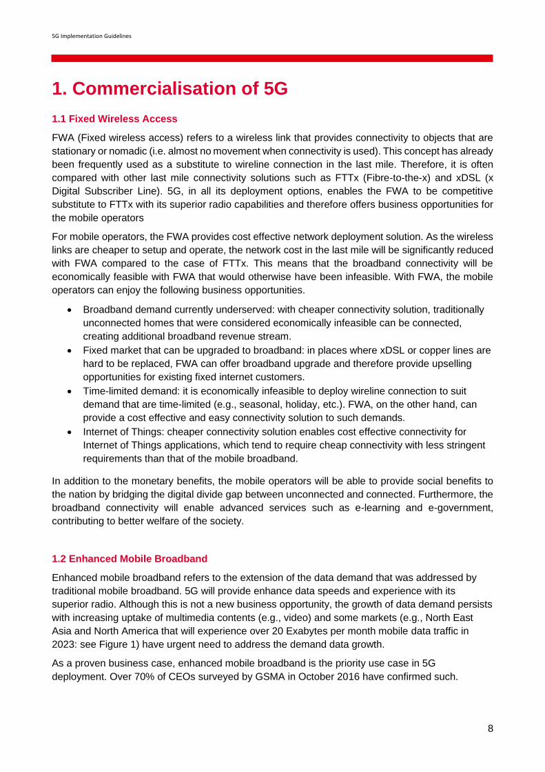
1.1 Fixed Wireless Access
FWA (Fixed wireless access) refers to a wireless link that provides connectivity to objects that are
stationary or nomadic (i.e. almost no movement when connectivity is used). This concept has already
been frequently used as a substitute to wireline connection in the last mile. Therefore, it is often
compared with other last mile connectivity solutions such as FTTx (Fibre-to-the-x) and xDSL (x
Digital Subscriber Line). 5G, in all its deployment options, enables the FWA to be competitive
substitute to FTTx with its superior radio capabilities and therefore offers business opportunities for
the mobile operators
For mobile operators, the FWA provides cost effective network deployment solution. As the wireless
links are cheaper to setup and operate, the network cost in the last mile will be significantly reduced
with FWA compared to the case of FTTx. This means that the broadband connectivity will be
economically feasible with FWA that would otherwise have been infeasible. With FWA, the mobile
operators can enjoy the following business opportunities.
• Broadband demand currently underserved: with cheaper connectivity solution, traditionally
unconnected homes that were considered economically infeasible can be connected,
creating additional broadband revenue stream.
• Fixed market that can be upgraded to broadband: in places where xDSL or copper lines are
hard to be replaced, FWA can offer broadband upgrade and therefore provide upselling
opportunities for existing fixed internet customers.
• Time-limited demand: it is economically infeasible to deploy wireline connection to suit
demand that are time-limited (e.g., seasonal, holiday, etc.). FWA, on the other hand, can
provide a cost effective and easy connectivity solution to such demands.
• Internet of Things: cheaper connectivity solution enables cost effective connectivity for
Internet of Things applications, which tend to require cheap connectivity with less stringent
requirements than that of the mobile broadband.
In addition to the monetary benefits, the mobile operators will be able to provide social benefits to
the nation by bridging the digital divide gap between unconnected and connected. Furthermore, the
broadband connectivity will enable advanced services such as e-learning and e-government,
contributing to better welfare of the society.
1.2 Enhanced Mobile Broadband
Enhanced mobile broadband refers to the extension of the data demand that was addressed by
traditional mobile broadband. 5G will provide enhance data speeds and experience with its
superior radio. Although this is not a new business opportunity, the growth of data demand persists
with increasing uptake of multimedia contents (e.g., video) and some markets (e.g., North East
Asia and North America that will experience over 20 Exabytes per month mobile data traffic in
2023: see Figure 1) have urgent need to address the demand data growth.
As a proven business case, enhanced mobile broadband is the priority use case in 5G
deployment. Over 70% of CEOs surveyed by GSMA in October 2016 have confirmed such.

5G Implementation Guidelines
9
Although connectivity yields low margin, it offers stable revenue stream that will be able to bankroll
the deployment of 5G to suit 5G use cases other than mobile broadband. Furthermore, as mobile
broadband is the key value proposition that is offered by the operator, excelling in enhanced
mobile broadband will differentiate the early adopter from its competitors. Therefore, although
being traditional business case, enhanced mobile broadband will be an integral part of 5G
commercialisation.
Figure 1: Global Mobile Data Traffic (Source: Ericsson)

5G Implementation Guidelines
10
2 Prerequisite for initial
5G NSA Option 3 launch
5G Implementation Guidelines
11
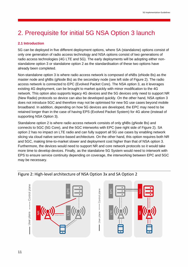
2. Prerequisite for initial 5G NSA Option 3 launch
2.1 Introduction
5G can be deployed in five different deployment options, where SA (standalone) options consist of
only one generation of radio access technology and NSA options consist of two generations of
radio access technologies (4G LTE and 5G). The early deployments will be adopting either non-
standalone option 3 or standalone option 2 as the standardisation of these two options have
already been completed.
Non-standalone option 3 is where radio access network is composed of eNBs (eNode Bs) as the
master node and gNBs (gNode Bs) as the secondary node (see left side of Figure 2). The radio
access network is connected to EPC (Evolved Packet Core). The NSA option 3, as it leverages
existing 4G deployment, can be brought to market quickly with minor modification to the 4G
network. This option also supports legacy 4G devices and the 5G devices only need to support NR
(New Radio) protocols so device can also be developed quickly. On the other hand, NSA option 3
does not introduce 5GC and therefore may not be optimised for new 5G use cases beyond mobile
broadband. In addition, depending on how 5G devices are developed, the EPC may need to be
retained longer than in the case of having EPS (Evolved Packet System) for 4G alone (instead of
supporting NSA Option 3).
Standalone option 2 is where radio access network consists of only gNBs (gNode Bs) and
connects to 5GC (5G Core), and the 5GC interworks with EPC (see right side of Figure 2). SA
option 2 has no impact on LTE radio and can fully support all 5G use cases by enabling network
slicing via cloud native service-based architecture. On the other hand, this option requires both NR
and 5GC, making time-to-market slower and deployment cost higher than that of NSA option 3.
Furthermore, the devices would need to support NR and core network protocols so it would take
more time to develop devices. Finally, as the standalone 5G System would need to interwork with
EPS to ensure service continuity depending on coverage, the interworking between EPC and 5GC
may be necessary.
Figure 2: High-level architecture of NSA Option 3x and SA Option 2

5G Implementation Guidelines
12
2.2 Spectrum
2.2.1 Bands earmarked for 5G and their possible utilisation
Availability of a suitable amount of spectrum is the most important prerequisite to launch 5G. While
globally harmonised bands will be allocated formally at WRC-19, several countries and regions
have already identified candidate bands and in some cases already allocated them.
When 5G deployment is driven by providing enhanced mobile broadband, the S and C bands,
communications bands extending from 2GHz to 4GHz and 4GHz to 8GHz respectively,
accommodate the 3.4GHz to 4.2 GHz frequency range which seems to be the most suitable
option. These bands have been identified in many countries as primary bands for 5G and as
Figure 3 shows, global harmonisation seems feasible in the lower part of such bands thus
unlocking economies of scale in devices.
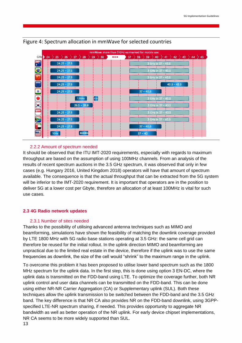
Another band that has been gaining popularity for use in 5G is the so called millimeter wave band
that includes spectrum spanning from 24GHz to 29.5GHz as well as spectrum in the 37GHz to
43.5GHz. The very fast attenuation of the radio signal at these frequencies has cast doubts on the
potential of using this spectrum to provide wide area coverage especially in the uplink direction
where MIMO and beamforming may not be as effective as in the downlink, however field trials and
simulations indicate that there is a key role to be played by mmWave in 5G.
28GHz for example, is the band used for many of the Fixed Wireless Access trials and commercial
launches and radio cells operating in mmWave are suitable for creating a thick capacity layer
where needed (hotspots) as well as for many enterprise scenarios.
The main attractiveness of mmWave, as Figure 4 shows, is the availability of a very large
bandwidth and the strong potential for global harmonization.
Figure 3: Spectrum in the S and C bands earmarked for use in 5G in selected
countries
5G Implementation Guidelines
13
Figure 4: Spectrum allocation in mmWave for selected countries
2.2.2 Amount of spectrum needed
It should be observed that the ITU IMT-2020 requirements, especially with regards to maximum
throughput are based on the assumption of using 100MHz channels. From an analysis of the
results of recent spectrum auctions in the 3.5 GHz spectrum, it was observed that only in few
cases (e.g. Hungary 2016, United Kingdom 2018) operators will have that amount of spectrum
available. The consequence is that the actual throughput that can be extracted from the 5G system
will be inferior to the IMT-2020 requirement. It is important that operators are in the position to
deliver 5G at a lower cost per Gbyte, therefore an allocation of at least 100MHz is vital for such
use cases.
2.3 4G Radio network updates
2.3.1 Number of sites needed
Thanks to the possibility of utilising advanced antenna techniques such as MIMO and
beamforming, simulations have shown the feasibility of matching the downlink coverage provided
by LTE 1800 MHz with 5G radio base stations operating at 3.5 GHz: the same cell grid can
therefore be reused for the initial rollout. In the uplink direction MIMO and beamforming are
unpractical due to the limited real estate in the device, therefore if the uplink was to use the same
frequencies as downlink, the size of the cell would “shrink” to the maximum range in the uplink.
To overcome this problem it has been proposed to utilise lower band spectrum such as the 1800
MHz spectrum for the uplink data. In the first step, this is done using option 3 EN-DC, where the
uplink data is transmitted on the FDD-band using LTE. To optimize the coverage further, both NR
uplink control and user data channels can be transmitted on the FDD-band. This can be done
using either NR-NR Carrier Aggregation (CA) or Supplementary uplink (SUL). Both these
techniques allow the uplink transmission to be switched between the FDD-band and the 3.5 GHz
band. The key difference is that NR CA also provides NR on the FDD-band downlink, using 3GPP-
specified LTE-NR spectrum sharing, if needed. This provides opportunity to aggregate NR
bandwidth as well as better operation of the NR uplink. For early device chipset implementations,
NR CA seems to be more widely supported than SUL.

5G Implementation Guidelines
14
Note: In general it is possible to use CA in conjunction with DC. That is CCs can be aggregated (in
E-UTRA and/or NR) and then DC is applied.
2.3.2 LTE upgrade to support EN-DC (Option 3)
For a successful deployment of EN-DC the 4G network needs to support dual connectivity
between E-UTRAN (LTE) and NR. This enhancement allows a device to consume radio resources
provided by both 4G and 5G. Typically the 4G radio will be used to carry control signalling while
NR and/or LTE will be used for user data. Three variants of the NSA solution have been defined
each producing a different impact on the LTE network.
Option 3 uses the MN (Master Node) terminated MCG (Master Cell Group) bearer for signalling.
There are a few variants for data bearer configuration within Option 3. The industry main-stream is
to use an SN-terminated split bearer (sometimes referred to as “Option 3x”). This variant has low
impact on EPC and enables data to route directly to the NR gNB to avoid excessive user plane
load on the existing LTE eNB, which was designed for 4G LTE traffic load and not additional NR
traffic load. As service continuity after loss of 5G radio coverage is more graceful in this variant, it
also minimizes excessive signalling traffic between RAN and core.
2.3.3 Considerations in aligning maintenance of LTE sites
When existing LTE network is upgraded to EN-DC (dual connectivity between master eNB and
secondary gNB), the maintenance of the LTE network may also be affected. While the
maintenance window and downtime are left up to operator’s discretion, operators should be
mindful of disruption in service for traditional 4G subscribers as well as 5G subscribers when
maintaining LTE sites. That is, when a eNB is down due to maintenance, both 4G (standalone
LTE) subscribers and 5G (EN-DC) subscribers will not be able to access the particular eNB.
In many commercial deployments, LTE networks will be overlaid on multiple bands and therefore
will not significantly impact customer experience during downtime of a particular eNB. However,
some degree of consideration must be taken into account to optimize 5G customer experience:
aligning the downtime of master eNB and secondary gNB.
This issue may also be dependent on the physical implementation of the eNB and gNB
functionalities at the cell site.
2.3.4 Supporting dynamic spectrum sharing
While there are many spectrum bands that are being allocated for 5G, the existing 4G spectrum
bands are still an important asset of the operator. Dynamic Spectrum Sharing (DSS) is a technology
that enables operators to use this important asset of 4G spectrum in providing 5G NR. The spectrum
resource can be dynamically shared among 4G LTE and 5G NR, differentiating this technology from
traditional spectrum refarming where 4G spectrum bands have to be completely cleared before it
can be used for 5G NR.
With DSS, the spectrum can be dynamically allocated to 4G LTE and 5G NR such that the utilization
of spectrum resources can be maximized. This also means that operators can avoid inefficient
spectrum utilization for 5G NR during the initial deployment where there is low penetration of devices.
As users of 5G NR increase, more spectrum resource can be allocated to 5G, leading to smooth
introduction of 5G NR in an existing 4G network.
The costs in deploying DSS, however, may be a hurdle in adopting it. Deploying DSS is easy if the
operator has an upgraded LTE infrastructure because it only requires software upgrade. On the
other hand, if the operator has legacy LTE infrastructure, the infrastructure must be upgraded before

5G Implementation Guidelines
15
implementing software upgrade. In the latter case, the operator can decide to do a quick nationwide
upgrade and NR deployment in its bands, or it can gradually upgrade its infrastructure and deploy
NR with DSS in incremental geographical areas.
2.4 4G Core network updates
4G Core network updating considerations mainly include option 3/3a/3x networking comparison,
4G core network upgrade strategy, network function upgrading.
2.4.1 Option 3/3a/3x Networking Comparison
The standardised NSA EPC networking architecture includes Option 3, Option 3a, and Option 3x.
In the Option 3 networking mode, the X2 interface traffic between eNB and gNB has NSA user plane
traffic. This traffic is huge. The core network needs to increase the bandwidth of the S1-U interface
to meet the LTE/NSA transmission requirements.
In the Option 3a networking mode, there is only control plane traffic in the X2 interface. So the X2
traffic is very small.
In the Option 3x networking mode, there is a little LTE user plane traffic in the X2 interface.
From the perspective of the impact on the existing network, the Option 3x is relatively small and
has become the mainstream choice for NSA networking. By using 4G as the anchor point of the
control plane, it can meet good service continuity and support rapid network construction in the
initial stage of 5G deployment.
Figure 5: NSA Option 3/3a/3x Networking Mode
5G Implementation Guidelines
16
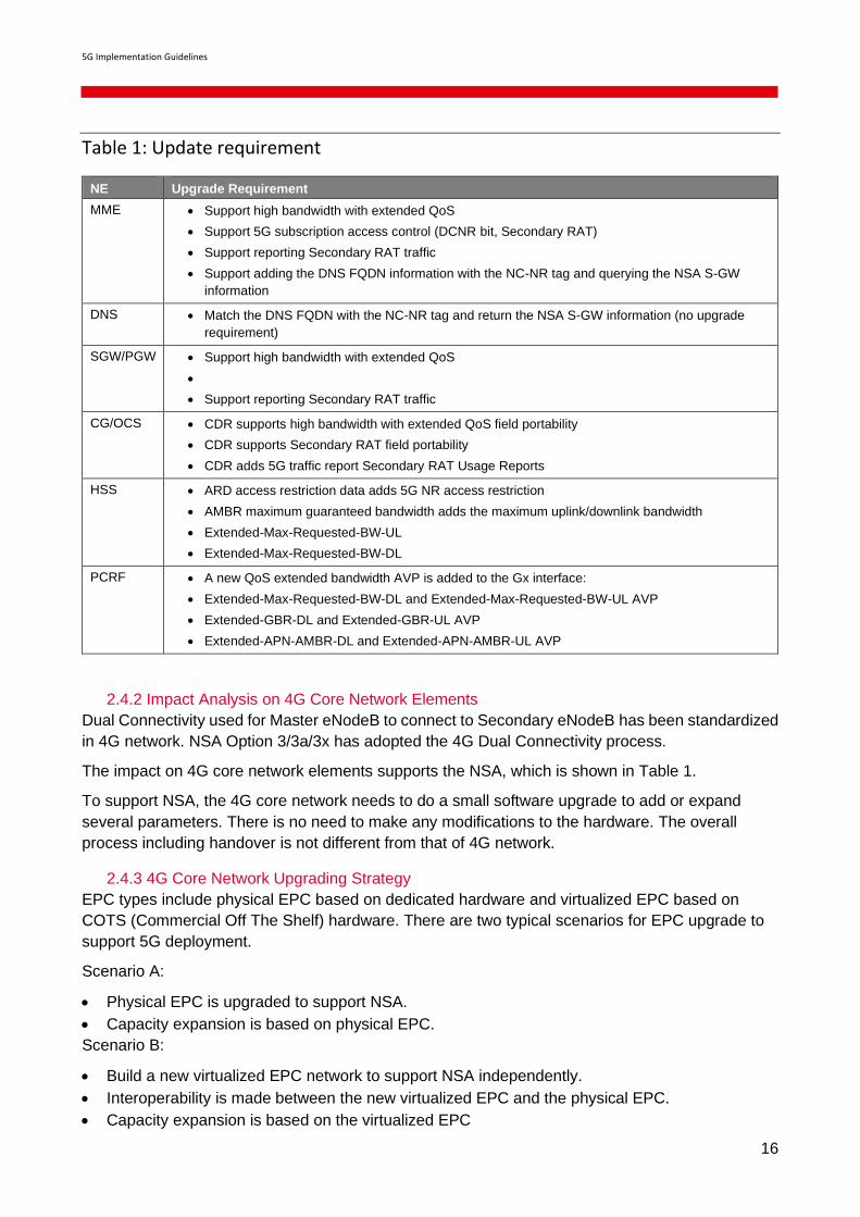
Table 1: Update requirement
NE Upgrade Requirement
MME • Support high bandwidth with extended QoS
• Support 5G subscription access control (DCNR bit, Secondary RAT)
• Support reporting Secondary RAT traffic
• Support adding the DNS FQDN information with the NC-NR tag and querying the NSA S-GW
information
DNS • Match the DNS FQDN with the NC-NR tag and return the NSA S-GW information (no upgrade
requirement)
SGW/PGW • Support high bandwidth with extended QoS
•
• Support reporting Secondary RAT traffic
CG/OCS • CDR supports high bandwidth with extended QoS field portability
• CDR supports Secondary RAT field portability
• CDR adds 5G traffic report Secondary RAT Usage Reports
HSS • ARD access restriction data adds 5G NR access restriction
• AMBR maximum guaranteed bandwidth adds the maximum uplink/downlink bandwidth
• Extended-Max-Requested-BW-UL
• Extended-Max-Requested-BW-DL
PCRF • A new QoS extended bandwidth AVP is added to the Gx interface:
• Extended-Max-Requested-BW-DL and Extended-Max-Requested-BW-UL AVP
• Extended-GBR-DL and Extended-GBR-UL AVP
• Extended-APN-AMBR-DL and Extended-APN-AMBR-UL AVP
2.4.2 Impact Analysis on 4G Core Network Elements
Dual Connectivity used for Master eNodeB to connect to Secondary eNodeB has been standardized
in 4G network. NSA Option 3/3a/3x has adopted the 4G Dual Connectivity process.
The impact on 4G core network elements supports the NSA, which is shown in Table 1.
To support NSA, the 4G core network needs to do a small software upgrade to add or expand
several parameters. There is no need to make any modifications to the hardware. The overall
process including handover is not different from that of 4G network.
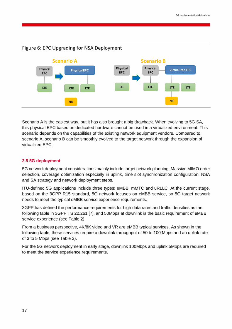
2.4.3 4G Core Network Upgrading Strategy
EPC types include physical EPC based on dedicated hardware and virtualized EPC based on
COTS (Commercial Off The Shelf) hardware. There are two typical scenarios for EPC upgrade to
support 5G deployment.
Scenario A:
• Physical EPC is upgraded to support NSA.
• Capacity expansion is based on physical EPC.
Scenario B:
• Build a new virtualized EPC network to support NSA independently.
• Interoperability is made between the new virtualized EPC and the physical EPC.
• Capacity expansion is based on the virtualized EPC
5G Implementation Guidelines
17
Figure 6: EPC Upgrading for NSA Deployment
Scenario A is the easiest way, but it has also brought a big drawback. When evolving to 5G SA,
this physical EPC based on dedicated hardware cannot be used in a virtualized environment. This
scenario depends on the capabilities of the existing network equipment vendors. Compared to
scenario A, scenario B can be smoothly evolved to the target network through the expansion of
virtualized EPC.
2.5 5G deployment
5G network deployment considerations mainly include target network planning, Massive MIMO order
selection, coverage optimization especially in uplink, time slot synchronization configuration, NSA
and SA strategy and network deployment steps.
ITU-defined 5G applications include three types: eMBB, mMTC and uRLLC. At the current stage,
based on the 3GPP R15 standard, 5G network focuses on eMBB service, so 5G target network
needs to meet the typical eMBB service experience requirements.
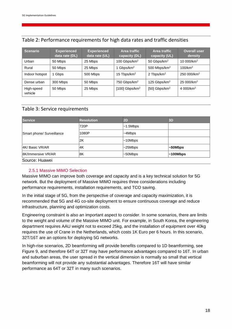
3GPP has defined the performance requirements for high data rates and traffic densities as the
following table in 3GPP TS 22.261 [7], and 50Mbps at downlink is the basic requirement of eMBB
service experience (see Table 2)
From a business perspective, 4K/8K video and VR are eMBB typical services. As shown in the
following table, these services require a downlink throughput of 50 to 100 Mbps and an uplink rate
of 3 to 5 Mbps (see Table 3).
For the 5G network deployment in early stage, downlink 100Mbps and uplink 5Mbps are required
to meet the service experience requirements.
5G Implementation Guidelines
18
Table 2: Performance requirements for high data rates and traffic densities
Scenario Experienced
data rate (DL)
Experienced
data rate (UL)
Area traffic
capacity (DL)
Area traffic
capacity (UL)
Overall user
density
Urban 50 Mbps 25 Mbps 100 Gbps/km2 50 Gbps/km2 10 000/km2
Rural 50 Mbps 25 Mbps 1 Gbps/km2 500 Mbps/km2 100/km2
Indoor hotspot 1 Gbps 500 Mbps 15 Tbps/km2 2 Tbps/km2 250 000/km2
Dense urban 300 Mbps 50 Mbps 750 Gbps/km2 125 Gbps/km2 25 000/km2
High-speed
vehicle
50 Mbps 25 Mbps [100] Gbps/km2 [50] Gbps/km2 4 000/km2
Table 3: Service requirements
Service Resolution 2D 3D
Smart phone/ Surveillance
720P ~1.5Mbps
1080P ~4Mbps
2K ~10Mbps
4K/ Basic VR/AR 4K ~25Mbps ~50Mbps
8K/Immersive VR/AR 8K ~50Mbps ~100Mbps
Source: Huawei
2.5.1 Massive MIMO Selection
Massive MIMO can improve both coverage and capacity and is a key technical solution for 5G
network. But the deployment of Massive MIMO requires three considerations including
performance requirements, installation requirements, and TCO saving.
In the initial stage of 5G, from the perspective of coverage and capacity maximization, it is
recommended that 5G and 4G co-site deployment to ensure continuous coverage and reduce
infrastructure, planning and optimization costs.
Engineering constraint is also an important aspect to consider. In some scenarios, there are limits
to the weight and volume of the Massive MIMO unit. For example, in South Korea, the engineering
department requires AAU weight not to exceed 25kg, and the installation of equipment over 40kg
requires the use of Crane in the Netherlands, which costs 1K Euro per 6 hours. In this scenario,
32T/16T are an options for deploying 5G networks.
In high-rise scenarios, 2D beamforming will provide benefits compared to 1D beamforming, see
Figure 9, and therefore 64T or 32T may have performance advantages compared to 16T. In urban
and suburban areas, the user spread in the vertical dimension is normally so small that vertical
beamforming will not provide any substantial advantages. Therefore 16T will have similar
performance as 64T or 32T in many such scenarios.

5G Implementation Guidelines
19
Figure 7: Comparison between 64T/32T and 16T
5G network deployment needs to fully consider performance, cost, space and weight limitation,
etc. The most cost effective configuration, 64T, 32T or 16T may be different for different
deployment scenarios due to the different performance benefits in the scenarios, respectively.
64T/32T tends to perform better in dense-urban high-rise scenarios and hence may be more cost
efficient, whereas 32T or 16T tend to be more cost efficient in urban and suburban scenarios.
2T2R/4T4R/8T8R solution should be considered as a basic configuration for 5G deployment,
deploying 16T16R/32T32R/64T64R to meet capacity requirements in those sites that need
capacity upgrades and are heavy loaded.
2.5.2 Coverage Enhancement
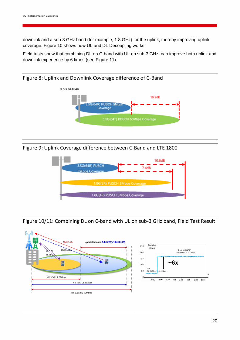
C-band is the primary band for 5G network and it has the large bandwidth making it perfect for 5G
eMBB services. Downlink coverage is better than uplink coverage on C-band spectrum due to the
large downlink transmit power of the gNodeB and to disproportion in uplink and downlink timeslot
allocations of NR. The application of technologies such as beamforming and cell-specific reference
signal (CRS)-free reduces downlink interference and further increases the difference between C-
band uplink and downlink coverage. As shown in Figure 8, taking the downlink 50Mbps and the
uplink 5Mbps as an example, the C-band uplink and downlink coverage differs by 16.2dB.
The C-Band downlink can achieve the similar coverage as the LTE 1800MHz, but there is
limitation in the uplink coverage and becomes 5G deployment bottleneck which will affect the user
experience. As shown in Figure 9, the difference between C-Band and LTE 1800MHz uplink
coverage is 7.6 dB for 2R and 10.4dB for 4R.
3GPP Release 15 introduces two mechanisms to handle the limited uplink coverage on the higher
bands, namely NR Carrier Aggregation (CA) and supplementary uplink (SUL). The use of these
mechanisms effectively utilize idle sub-3 GHz band resources, improve the uplink coverage of C-
band, and enable the provisioning of 5G services in a wider area. Both solutions, NR CA and SUL,
offer transport of UL user data using sub-3GHz band NR radio resources. NR CA provides the
added benefit of also providing sub-3GHz DL user data support. Based on the SUL, the feature
Uplink and Downlink Decoupling defines new paired spectrums, where C-band is used for the
5G Implementation Guidelines
20
downlink and a sub-3 GHz band (for example, 1.8 GHz) for the uplink, thereby improving uplink
coverage. Figure 10 shows how UL and DL Decoupling works.
Field tests show that combining DL on C-band with UL on sub-3 GHz can improve both uplink and
downlink experience by 6 times (see Figure 11).
Figure 8: Uplink and Downlink Coverage difference of C-Band
Figure 9: Uplink Coverage difference between C-Band and LTE 1800
Figure 10/11: Combining DL on C-band with UL on sub-3 GHz band, Field Test Result
5G Implementation Guidelines
21
Figure 12: Interference and Guardband with non-synchronization time slot
Figure 13: 4:1 and 8:2 time slot configuration
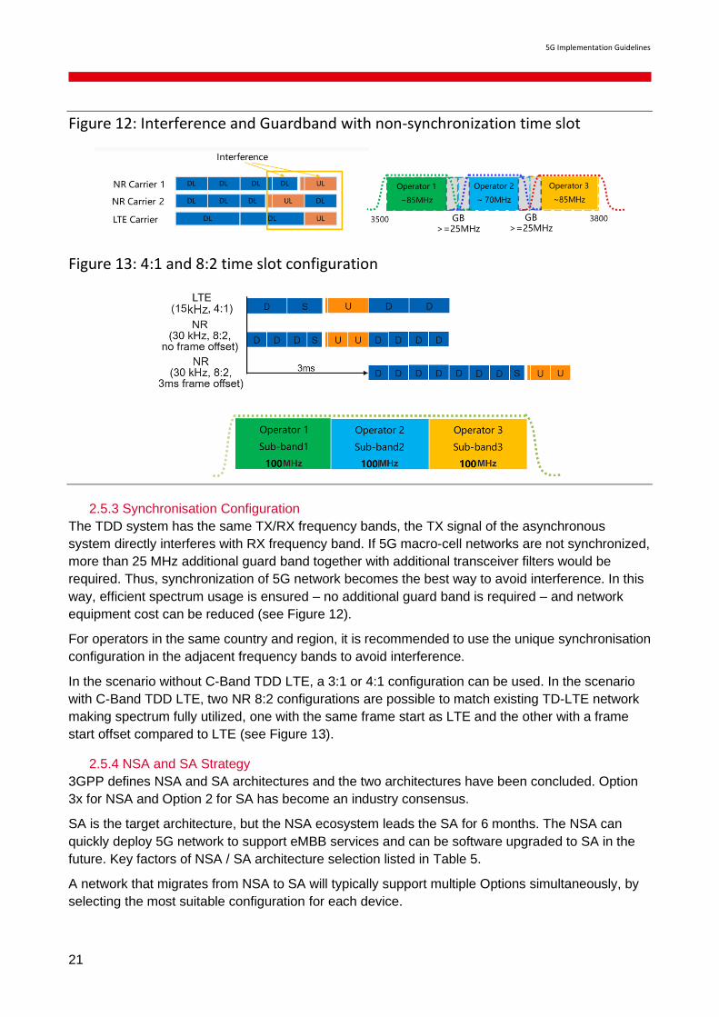
2.5.3 Synchronisation Configuration
The TDD system has the same TX/RX frequency bands, the TX signal of the asynchronous
system directly interferes with RX frequency band. If 5G macro-cell networks are not synchronized,
more than 25 MHz additional guard band together with additional transceiver filters would be
required. Thus, synchronization of 5G network becomes the best way to avoid interference. In this
way, efficient spectrum usage is ensured – no additional guard band is required – and network
equipment cost can be reduced (see Figure 12).
For operators in the same country and region, it is recommended to use the unique synchronisation
configuration in the adjacent frequency bands to avoid interference.
In the scenario without C-Band TDD LTE, a 3:1 or 4:1 configuration can be used. In the scenario
with C-Band TDD LTE, two NR 8:2 configurations are possible to match existing TD-LTE network
making spectrum fully utilized, one with the same frame start as LTE and the other with a frame
start offset compared to LTE (see Figure 13).
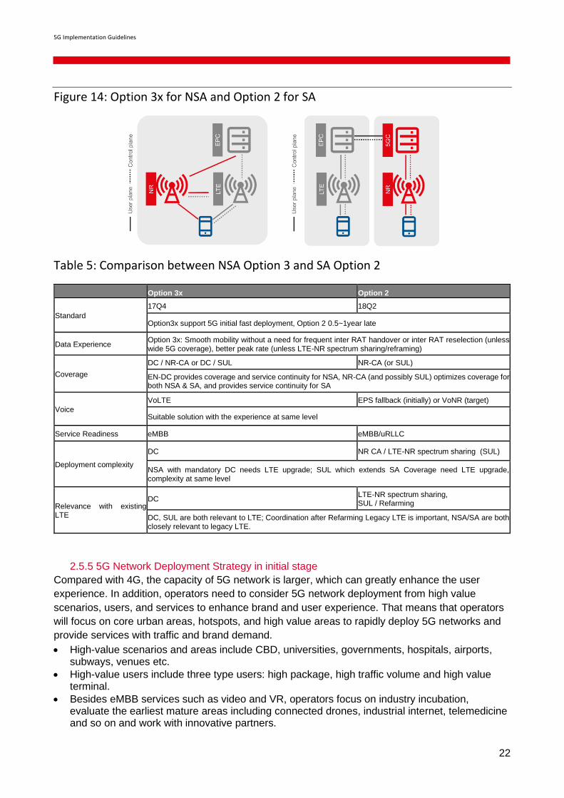
2.5.4 NSA and SA Strategy
3GPP defines NSA and SA architectures and the two architectures have been concluded. Option
3x for NSA and Option 2 for SA has become an industry consensus.
SA is the target architecture, but the NSA ecosystem leads the SA for 6 months. The NSA can
quickly deploy 5G network to support eMBB services and can be software upgraded to SA in the
future. Key factors of NSA / SA architecture selection listed in Table 5.
A network that migrates from NSA to SA will typically support multiple Options simultaneously, by
selecting the most suitable configuration for each device.
5G Implementation Guidelines
22
Figure 14: Option 3x for NSA and Option 2 for SA
Table 5: Comparison between NSA Option 3 and SA Option 2
Option 3x Option 2
Standard
17Q4 18Q2
Option3x support 5G initial fast deployment, Option 2 0.5~1year late
Data Experience Option 3x: Smooth mobility without a need for frequent inter RAT handover or inter RAT reselection (unless wide 5G coverage), better peak rate (unless LTE-NR spectrum sharing/reframing)
Coverage
DC / NR-CA or DC / SUL NR-CA (or SUL)
EN-DC provides coverage and service continuity for NSA, NR-CA (and possibly SUL) optimizes coverage for both NSA & SA, and provides service continuity for SA
Voice
VoLTE EPS fallback (initially) or VoNR (target)
Suitable solution with the experience at same level
Service Readiness eMBB eMBB/uRLLC
Deployment complexity
DC NR CA / LTE-NR spectrum sharing (SUL)
NSA with mandatory DC needs LTE upgrade; SUL which extends SA Coverage need LTE upgrade, complexity at same level
Relevance with existing LTE
DC LTE-NR spectrum sharing, SUL / Refarming
DC, SUL are both relevant to LTE; Coordination after Refarming Legacy LTE is important, NSA/SA are both closely relevant to legacy LTE.
2.5.5 5G Network Deployment Strategy in initial stage
Compared with 4G, the capacity of 5G network is larger, which can greatly enhance the user
experience. In addition, operators need to consider 5G network deployment from high value
scenarios, users, and services to enhance brand and user experience. That means that operators
will focus on core urban areas, hotspots, and high value areas to rapidly deploy 5G networks and
provide services with traffic and brand demand.
• High-value scenarios and areas include CBD, universities, governments, hospitals, airports, subways, venues etc.
• High-value users include three type users: high package, high traffic volume and high value terminal.
• Besides eMBB services such as video and VR, operators focus on industry incubation, evaluate the earliest mature areas including connected drones, industrial internet, telemedicine and so on and work with innovative partners.

5G Implementation Guidelines
23
Figure 15: 3 Areas for Initial 5G Deployment
2.6 Transmission / backhaul
Fronthaul implementation is considered as a key element in order to manage mobile data growth,
reduced latency required by 5G use cases and provide scalability in terms of RAN densification,
micro cells deployment and future evolutions towards Cloud RAN.
Regarding interfaces to be adopted, eCPRI and O-RAN seem to be the main candidate for RRU and
CU/DU connection for the 5G scenario, with a bandwidth granularity of 25 Gbit/s. Even though CPRI
is currently proposed for 4G Fronthaul deployment, the aim should be to adopt a single interface,
eCPRI, for both 4G and 5G networks with defined requirements in term of Jitter/latency.
It is still to be investigated the opportunity to deploy also Midhaul segment, e.g. by mean of
aggregation rings between Distributed Unit (DU) and Centralized Unit (CU).
Given the fact that 5G networks are mainly based on TDD multiplexing, accurate Phase
synchronization is mandatory. The implementation of a GPS receiver on each radio system
represents a potential solution, even though this approach comes with high deployment cost and
reliability or security issues. Another solution is based on PTP ITU profiles implementation in Partial
Timing Support or Full Timing Support.
IPSec deployment in 5G transport network will have to consider potential Edge Computing
implementation. In fact, the shift of Virtualized Functions at the edge of the network will imply to not
use IPSec or terminate IPsec tunnels at Edge POP level.
2.6.1 Considerations in augmenting existing transmission networks
NSA Option 3 is where existing LTE network is upgraded to EN-DC connected to EPC. This
means that there is likely to be additional data load and requirement (e.g., latency and
synchronisation), because the gNBs will need to accommodate some traffic and the requirement
will become more stringent depending on the amount of traffic handled by gNB. This needs to be
addressed by the existing transport network that have been dimensioned for 4G use cases and
requirements, requiring augmentation of the transport network.
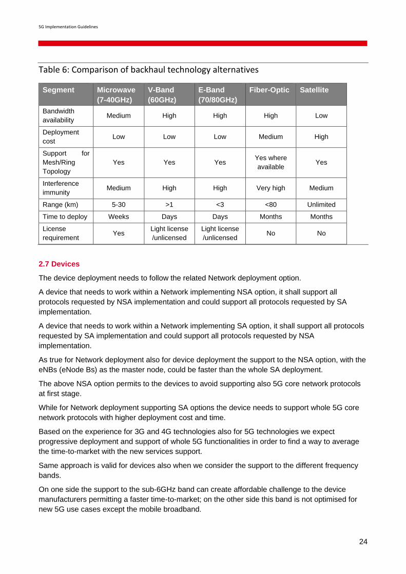
In this case, the operator may choose to adopt new and/or expand transport network. An
alternative in expanding transport network is described in Table 6 for information (Source: Mobile
Backhaul Options, GSMA).
5G Implementation Guidelines
24
Table 6: Comparison of backhaul technology alternatives
Segment Microwave
(7-40GHz)
V-Band
(60GHz)
E-Band
(70/80GHz)
Fiber-Optic Satellite
Bandwidth
availability Medium High High High Low
Deployment
cost Low Low Low Medium High
Support for
Mesh/Ring
Topology
Yes Yes Yes Yes where
available Yes
Interference
immunity Medium High High Very high Medium
Range (km) 5-30 >1 <3 <80 Unlimited
Time to deploy Weeks Days Days Months Months
License
requirement Yes
Light license
/unlicensed
Light license
/unlicensed No No
2.7 Devices
The device deployment needs to follow the related Network deployment option.
A device that needs to work within a Network implementing NSA option, it shall support all
protocols requested by NSA implementation and could support all protocols requested by SA
implementation.
A device that needs to work within a Network implementing SA option, it shall support all protocols
requested by SA implementation and could support all protocols requested by NSA
implementation.
As true for Network deployment also for device deployment the support to the NSA option, with the
eNBs (eNode Bs) as the master node, could be faster than the whole SA deployment.
The above NSA option permits to the devices to avoid supporting also 5G core network protocols
at first stage.
While for Network deployment supporting SA options the device needs to support whole 5G core
network protocols with higher deployment cost and time.
Based on the experience for 3G and 4G technologies also for 5G technologies we expect
progressive deployment and support of whole 5G functionalities in order to find a way to average
the time-to-market with the new services support.
Same approach is valid for devices also when we consider the support to the different frequency
bands.
On one side the support to the sub-6GHz band can create affordable challenge to the device
manufacturers permitting a faster time-to-market; on the other side this band is not optimised for
new 5G use cases except the mobile broadband.
5G Implementation Guidelines
25
Instead the so called mmWave bands are the optimised bands to support the whole 5G services
and use cases; but due to the very fast attenuation of the radio signal and the difficulties to
manage so high frequencies their support can create big challenges to device manufacturers
requesting more time and higher cost compared with only Sub6GHz support.
Based on above aspects the test-set related to the 5G devices should be customized based on
device functionalities support, considering different sub-set related to NSA, SA, Sub6GHz,
mmWave, VoNR.
2.8 Network Sharing
Mobile networks operate on a network infrastructure, which is not only limited to electronic
components, but also includes passive elements such as physical sites and towers that are
required to operate network. As network have been densified from previous generations to 4G,
sharing of network infrastructure is becoming more popular. This is expected to continue in the 5G
era where networks will be densified even more. Network sharing comes in many forms, but it is
mostly classified according to the technological components that are being shared (see Figure 16).
Passive infrastructure sharing is where non-electronic infrastructure at a cell site, such as power
supply and management system, and physical elements such backhaul transport networks are
shared. This form can be further classified into site sharing, where physical sites of base stations
are shared, and shared backhaul, where transport networks from radio controller to base stations
are shared.
Active infrastructure sharing is sharing of electronic infrastructure of the network including radio
access network (consists of antennas/transceivers, base station, backhaul networks and controllers)
and core network (servers and core network functionalities). This form can be further classified into
MORAN (Multi-Operator Radio Access Network), where radio access networks is shared and
dedicated spectrum is used by each sharing operator, MOCN (Multi-Operator Core Network), where
radio access networks and spectrum are shared, and core network sharing, where servers and core
network functionalities are shared.
Note that passive infrastructure sharing is the simplest and can be implemented per sites, which
enables operators to easily share sites and maintain their strategic competitiveness depending on
the sites shared. Operation is also easier with this form of sharing because network equipment
remains separated. However, the cost saving potential of sharing is limited relative to other forms of
sharing.
MORAN and MOCN enables greater cost sharing potential than passive sharing, and they can be
implemented per sites and enables strategic differentiation. However, operation of network
equipment needs to be shared (or at least issues must be shared with participants) and therefore
increases the complexity of sharing relative to site sharing. Core network is complicated to operate
and to maintain strategic differentiation. It is important to note that core network sharing has not been
popular and only few cases have been suspected to be so.
5G Implementation Guidelines
26
Figure 16: Classification of network infrastructure sharing
2.8.1 Benefits of Sharing
BEREC [2] published a document where the following benefits are listed:
• Cost Savings benefits:
• passive sharing cost savings: [16%-35%] CAPEX, [16%-35%] OPEX;
• active sharing (excl. spectrum) cost savings: [33%-35%] CAPEX, [25%-33%] OPEX;
• active sharing (incl. spectrum) cost savings: [33%-45%] CAPEX, [30%-33%] OPEX;
• core network sharing: core network sharing cost savings are limited.
• Environmental benefits – reduces energy consumption, mitigate citizens’ concern over radiation
• Customer experience – sharing can lead to better quality of the services, better coverage,
higher data speed.
• Coverage obligation can be met
The reduced cost can be diverted to other services and innovation, maximizing the potential of the
capital resources of the mobile operator. Furthermore, network infrastructure sharing resolves
difficulties in acquiring sites for the access network, where sharing operators can jointly cooperate
to acquire sites. Consequently, the cost of 5G deployment can be reduced with sharing of
costs/difficulties associated with sites. The technical enablers in the 5G era such as SDN
(Software Defined Networking) and NFV (Network Function Virtualization) also makes the network
more accommodating to the network infrastructure sharing.
2.8.2 Obligations and challenges
Network infrastructure sharing may lead to hindrance in competition among mobile network
operators. When the network infrastructure is shared, it is inherently difficult to differentiate or
corroborate own network infrastructure to compete against the sharing partners. Whilst it is
possible to compete on the basis of services, the regulatory obligation of mobile networks tends to
focus on the network connectivity and consequently the infrastructure. This concern can be
minimized if the sharing is limited to the scope of passive infrastructure. As active components can
be differentiated while optimising the cost of passive infrastructure, competition among sharing
operators can still be active.
5G Implementation Guidelines
27
Furthermore, it is very challenging to consolidate existing network infrastructure to share. An
existing network is a result of planning and operations phases based on specific operator
requirements, and consolidating existing networks is likely to be difficult if any of the requirements
conflict. As NSA option 3 leverages existing LTE network infrastructure, it may also be challenging
to implement network infrastructure sharing, unless it is limited to new NR base stations. The
sharing of network infrastructure may be more feasible with SA option 2, where both radio access
and core networks will be newly deployed, given that the operators will collaborate from the
planning phase.
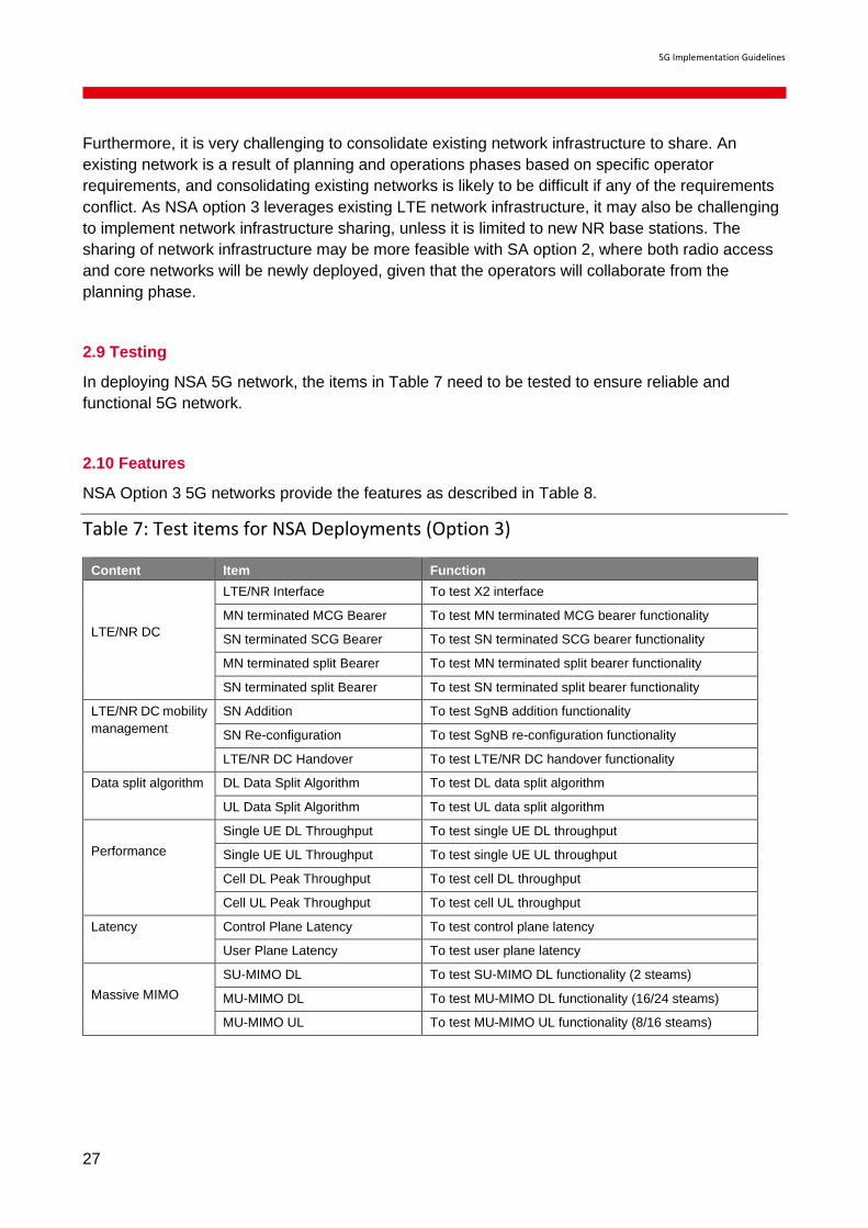
2.9 Testing
In deploying NSA 5G network, the items in Table 7 need to be tested to ensure reliable and
functional 5G network.
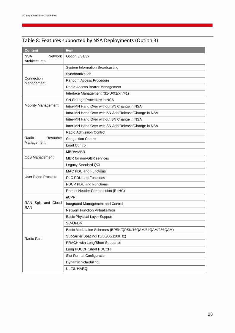
2.10 Features
NSA Option 3 5G networks provide the features as described in Table 8.
Table 7: Test items for NSA Deployments (Option 3)
Content Item Function
LTE/NR DC
LTE/NR Interface To test X2 interface
MN terminated MCG Bearer To test MN terminated MCG bearer functionality
SN terminated SCG Bearer To test SN terminated SCG bearer functionality
MN terminated split Bearer To test MN terminated split bearer functionality
SN terminated split Bearer To test SN terminated split bearer functionality
LTE/NR DC mobility
management
SN Addition To test SgNB addition functionality
SN Re-configuration To test SgNB re-configuration functionality
LTE/NR DC Handover To test LTE/NR DC handover functionality
Data split algorithm DL Data Split Algorithm To test DL data split algorithm
UL Data Split Algorithm To test UL data split algorithm
Performance
Single UE DL Throughput To test single UE DL throughput
Single UE UL Throughput To test single UE UL throughput
Cell DL Peak Throughput To test cell DL throughput
Cell UL Peak Throughput To test cell UL throughput
Latency Control Plane Latency To test control plane latency
User Plane Latency To test user plane latency
Massive MIMO
SU-MIMO DL To test SU-MIMO DL functionality (2 steams)
MU-MIMO DL To test MU-MIMO DL functionality (16/24 steams)
MU-MIMO UL To test MU-MIMO UL functionality (8/16 steams)
5G Implementation Guidelines
28
Table 8: Features supported by NSA Deployments (Option 3)
Content Item
NSA Network
Architectures
Option 3/3a/3x
Connection
Management
System Information Broadcasting
Synchronization
Random Access Procedure
Radio Access Bearer Management
Interface Management (S1-U/X2/Xn/F1)
Mobility Management
SN Change Procedure in NSA
Intra-MN Hand Over without SN Change in NSA
Intra-MN Hand Over with SN Add/Release/Change in NSA
Inter-MN Hand Over without SN Change in NSA
Inter-MN Hand Over with SN Add/Release/Change in NSA
Radio Resource
Management
Radio Admission Control
Congestion Control
Load Control
QoS Management
MBR/AMBR
MBR for non-GBR services
Legacy Standard QCI
User Plane Process
MAC PDU and Functions
RLC PDU and Functions
PDCP PDU and Functions
Robust Header Compression (RoHC)
RAN Split and Cloud
RAN
eCPRI
Integrated Management and Control
Network Function Virtualization
Radio Part
Basic Physical Layer Support
SC-OFDM
Basic Modulation Schemes (BPSK/QPSK/16QAM/64QAM/256QAM)
Subcarrier Spacing(15/30/60/120KHz)
PRACH with Long/Short Sequence
Long PUCCH/Short PUCCH
Slot Format Configuration
Dynamic Scheduling
UL/DL HARQ
5G Implementation Guidelines
29
2.11 Migration to virtualized network/Network Transformation [12]
5G core networks will be designed with the assumption that the network will be fully virtualized and
cloud native. In addition, 3GPP has standardized CUPS technology that decouples control and user
plane of the 4G core network. This means that the operators would need to consider stable migration
from their legacy 4G network consisting of proprietary equipment to a virtualized network.
In addition to transitioning to the new paradigm of core networks in 5G, virtualized networks possess
promising advantages in terms of costs, time to market and fostering service innovation. Before
adopting fully virtualized network of 5G core network, operators can familiarize themselves with the
new paradigm by migrating their legacy 4G networks to a virtual one. However, the migration to
virtual network is not free from hurdles and needs careful considerations.
GSMA Future Networks Programme conducted case studies of leading operators that have
virtualized their 4G core networks and IMS (IP Multimedia Subsystem). These leading operators all
point out that there are many challenges and risks in migrating a legacy network to a fully virtualized
network. First, ensuring carrier grade SLA (Service Level Agreement) on IT platform is a great
challenge, for example five 9s availability. This also leads to potential lock-in to specific IT vendors
as only few vendors would be able to provide telco-grade solutions. There is also challenge in
enlarged base of stakeholders and resulting integration of products. Finally, the cost can increase if
VNF (Virtual Network Function) and VI (Virtualized Infrastructure) managers are proprietary.
Fortunately, the experience of the operators can help other mobile operators in the migration journey
to fully virtualized network. In initial stages of virtualisation, single vendor approach may have
advantages as it avoids complicated troubleshooting and cross layer fault detection. Such integration
savings can also be realised lowering the Total Cost of Ownership. Second, an end-to-end design
of the network can help achieve the telco-grade quality as industry standards for virtualised
components are generally below telco-grade and hence end-to-end approach helps to overcome it.
Third, the operator organisation needs to reflect the shift in operations and management paradigm
associated with virtualized network, as the current organization fit for legacy operations and
management would not be appropriate. In relation to this point, operators may benefit from becoming
integrators of the equipment used in their networks and train staff accordingly, as virtualized network
is analogous to an integrated system for specific purposes.
Figure 17: Roaming architecture
LTE eNB gNB
MME SGW PGW
HSS PGW
vPCRF
hPCRF
VPLMN
HPLMN

5G Implementation Guidelines
30
2.12 Roaming
5G NSA Option 3 will not introduce any changes to the existing roaming architecture and procedures.
It is up to the VPLMN operator to allow inbound roamers to use 5GS NSA Option 3 or to only allow
SA/LTE (Option 1).
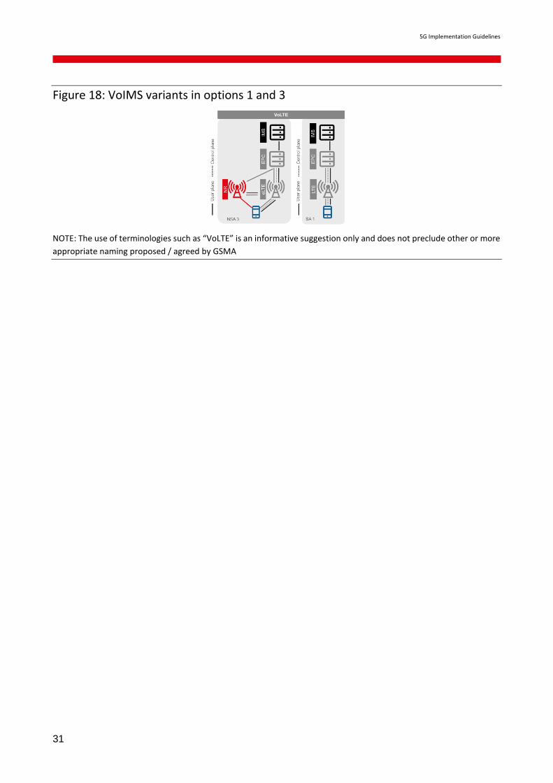
2.13 Services (IMS – Voice)
One of the important aspects of migration to 5G is the support of voice and related services (e.g.
SMS, conversational video). In what follows, however, the focus will be on IMS based services for
voice via 3GPP based 5G access network. Non-IMS based voice is out of scope here. Note that
the reasoning for IMS based voice (“VoIMS”) can apply for IMS based SMS (“SMSoIP”) and IMS
based conversational video (“VioIMS”). VoIMS refers here to the generic IMS based voice solution;
it includes the support of IMS based Emergency Services. VoIMS support over WLAN (“VoWiFi”)
and its interworking with VoIMS over 5G access is also out of scope.
The initial configuration corresponds to the use of VoIMS over LTE / EPC (“VoLTE” per IR.92 [1]).
It refers to the usage over legacy LTE system (EPS) - so called 3GPP architectural SA/LTE
(“Option 1”) - which can also be used by NSA/EN-DC (“Option 3”) (see Figure 18).
2.13.1 Roaming with VoIMS
Roaming support for VoIMS is is an important feature and is essentially based on IMS Roaming in
a 4G or 5G environment. The principle of IMS and in particular VoIMS roaming in a 4G
environment has been defined in IR.65 [3].
The Home Routed solution is usually the path for data / Internet roaming (e.g. for 3G and 4G) but
has been used in 4G for (Vo)IMS roaming because it offers a quicker and easier deployment
solution independent of the VPMN despite some constraints and additional standardisation effort
that was required (e.g. for Lawful Interception).
2.14 Outlook
The document will be open for contributions/suggestions and will keep evolving to provide support
for more deployment options and considerations. Currently, the following topics are planned for
further development.
Please contact [email protected] if you would like to contribute or suggest topic to be
covered by this document.
5G Implementation Guidelines
31
Figure 18: VoIMS variants in options 1 and 3
NOTE: The use of terminologies such as “VoLTE” is an informative suggestion only and does not preclude other or more
appropriate naming proposed / agreed by GSMA

5G Implementation Guidelines
32
Annex A Document Management
A.1 Document History
Version Date Brief Description of Change Approval
Authority
Editor /
Company
0.1 16-Oct-
2018
CR001 incorporated 5GNSA Sandra
Ondrusova /
CK Hutchison
0.2 27-Nov-
2018
CR002, CR003, CR004
incorporated
5GNSA Sandra
Ondrusova /
CK Hutchison
0.3 20-Dec-18 CR007 incorporated 5GNSA Sandra
Ondrusova /
CK Hutchison
0.4 4-Feb-
2019
CR009 incorporated 5GNSA Sandra
Ondrusova /
CK Hutchison
0.5 19-Feb-
2019
CR010, CR012, CR013, CR014,
CR015, CR016 incorporated
Section 3.15 modified
5GNSA Sandra
Ondrusova /
CK Hutchison
0.6 21-Feb-
2019
Figures updated, Section 3.15
modified 5GNSA Sandra
Ondrusova /
CK Hutchison
0.7 25-Feb-
2019
Editorial changes and revisions to
section 3.2 5GNSA Sandra
Ondrusova /
CK Hutchison
1.0 05-Mar-
2019
Editorial changes and approval by
5GNSA Group for publication 5GNSA Sandra
Ondrusova /
CK Hutchison
2.0 18-Jul-
2019
CR017 raised by Ericsson and
revised by 5GPCG approved. 5GPCG Sandra
Ondrusova /
CK Hutchison
2.1 14-Feb-
2020
CR018 raised by GSMA
approved by 5GPCG 5GPCG Sandra
Ondrusova /
CK Hutchison
Dongwook Kim
/ GSMA
A.2 Other Information
Type Description
Document Owner 5GPCG
Editor / Company Sandra Ondrusova / CK Hutchison
Dongwook Kim / GSMA

5G Implementation Guidelines
33
Reviewed & Approved by 5GPCG
It is our intention to provide a quality product for your use. If you find any errors or omissions,
please contact us with your comments. You may notify us at [email protected]
Your comments or suggestions & questions are always welcome.