5763 lapma
TRANSCRIPT

All tube 3.5/7MHz AM/CW portable transmitter (MAFTR-37A)
- Built in 2010 -
[The last renewal of this page: July. 21, 2010]
The Japanese CQ Magazines published in 1960's are where we can find a starting point of Amateur radio. I happened to find a very interesting artcle in there which atrracted me at once. That is a portable transceiver using eight tubes built in a jank cabinet for a measurement instrument having carrying grip at the top. Imagine, you go on a trip to the Kusatsu hot spring with this "portable" radio, staying in an old fashion traditional hot spring inn. Putting out a long wire antenna from the window of your room to enjoy QSOs with all over Japan on CW and AM! Oh, how nice! That is absolutely a very starting point of amateur radio!! I then started to eager to build the same rig drawn in a schematic diagram which attracted me in a glance. This is the article mentined. (Japanese CQ magazine, Feb. 1964 issue)


What an attractive simple circuit! It is obvious that current professional radios for amateurs using bunch of ICs and LSIs forming super high class circuit performs super.I leave these radios for amateur "professional operators", and I, who is amateur radio engineer, was excited with such a lovely old style radio, feeling it is a typical true worth of amateur.
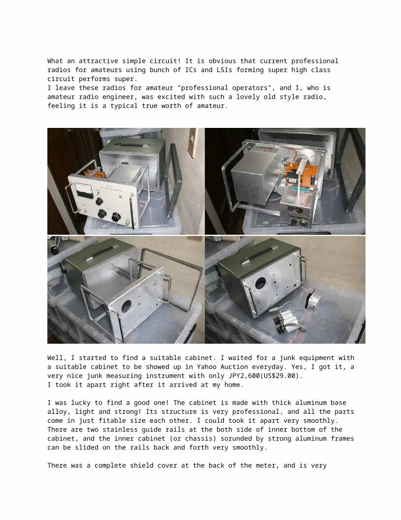
Well, I started to find a suitable cabinet. I waited for a junk equipment with a suitable cabinet to be showed up in Yahoo Auction everyday. Yes, I got it, a very nice junk measuring instrument with only JPY2,600(US$29.00). I took it apart right after it arrived at my home.
I was lucky to find a good one! The cabinet is made with thick aluminum base alloy, light and strong! Its structure is very professional, and all the parts come in just fitable size each other. I could took it apart very smoothly. There are two stainless guide rails at the both side of inner bottom of the cabinet, and the inner cabinet (or chassis) sorunded by strong aluminum frames can be slided on the rails back and forth very smoothly.
There was a complete shield cover at the back of the meter, and is very different from transmitter for amateurs. (Many transmitters have shield in most part of requried place, but normally, RF is very happy to be able to get out through the holes for the meter!) Oscilator unit is a perfect box with shield, and there is a smaller shielded box in it again. All the wirings are done through penetration terminal with bypass capacitor. The 100/10dB RF attenuator stepping by 1dB is also shielded completely and wired with RF connectors. Indeed, that's a professional equipment!
The below half of the above pictures were taken after the dismantlement. All I need seems to mount a

suitable sized chassis in an aluminum frame. Beautiful and strong, light and easy! This is the best choice for this project. If we buy a brandnew cabinet, it would cost us JPY10,000(US$110.00) at least. This costed me only JPY2,600, moreover, with valuable and expensive RF attenuator and shilded meter. Now building has started, putting its name as "MAFTR-37A"


Cutting and resizing aluminum chassis bought at a parts shop, I mounted it on the frame of cabinet for a junck measuring instrument. Using L-shape aluminum angled plate, I fixed it to the panel as well. I also installed a finishing panel over the panel existed, although nothing has started yet. Thhis means I will drill holes to the two panels sticked together.(Both panels are aluminum and doing it is easy.) This meter is manufactured in 1965, and is just fit to the radio for 1960's. I got it for only JPY300(US$3.00) in Yahoo Auction. Power transformer is also from the Auction, getting it for JPY2,500(US$28.00The aluminum frame structure and large handles on the front panel help the assembling and adjustment
very easy, enabling me to rotate the cabinet (chassis) to any directions.(Any six cubic respects could be the bottom
A large part is now on the front panel. A smaller vernier dial is for VFO, and a larger one is for tuning of the receiver. Two nobs below the meter are for LOAD (upper) and PLATE (lower)


I have completed it here at a dash. I used old IFTs being took apart from old Panasky Mark6 I found myself getting speed for works, but that is maybe because I have been doing a lot of works in pas one year, starting with restores of many old radios, taking apart juncks to get parts, and building MAFTX-50A (50MHz 10W AM/CW Heterodine Transmitter) It will be a very cute transceiver with eight(discluding a stabilizer tube) tubes
I mounted a piolot lamp in an old fashion which I happened to find in a parts shop in Akihabara. I used to love this lamp very much 40 years ago. I also could find a nob in an old fashion in Akihabara. I checked its looking installing chassis into the cabinet This pilot lamp is something that I thought I could never find again now in the market, but actually this 40 years old part was sold in an old parts shop in Akihabara! Especially, the one with a transparent glass cover is exactly the same part with the one that is used for TRIO's(KENWOOD) AM transmitter, TX-88A for the RF output monitor forty years ago. I used to love the feeling of the transparent crystal cutting, so I was so haapy and overjoyed with finding exactly the same thing what I have imaged together with the red one for the power pilot lamp
The external looking is completed already!? The external has finished before the inner works starts except lettering works. I am quite satisfied with this looking! It seems that inner works is not required, and I will be perfectly satisfied with just leave and display it!!?
Actually, I was lucky to meet with this junk cabinet. It meets the concept perfectly. I think I will start inner work after completing lettering works of the front panel. It's absolutely exciting! It's neat that super-excellent ears are required to listen to the signals
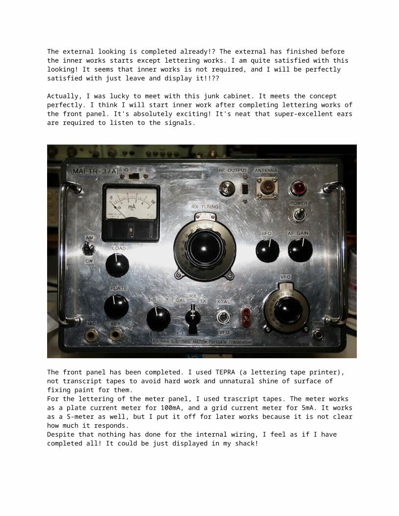
The front panel has been completed. I used TEPRA (a lettering tape printer), not transcript tapes to avoid hard work and unnatural shine of surface of fixing paint for them. For the lettering of the meter panel, I used trascript tapes. The meter works as a plate current meter for 100mA, and a grid current meter for 5mA. It works as a S-meter as well, but I put it off for later works because it is not clear how much it responds. Despite that nothing has done for the internal wiring, I feel as if I have completed all! It could be just displayed in my shack!

Wiring has been started now. First of all, I tried to complete the audio amplifire and receiver circuit. I want to enjoy first receiving it!

I used old TRIO's receiver coil kit S-B (3.5MHz-10.5MHz VC:430pF) which I got for JPY2,100(US$23.00) at the Yahoo Auction.
The matching network of the final stage (Pie-match) is commonly used as the antenna resonance circuit

of the receiver, and therefore, this part is indispensable for the receiver to work. I used a heatproof water pipe for the bobin. (Inner diameter: 20mm) This pipe is good in size to realize 25mm of outside diameter, and strong against a heat of the solder arms.
A coil located next to the socket for the final tube is originally a receiver coil, but is used also as the tank coil for driver stage. (Designed to synchronize RX frequency tuning with TX drive tuning.) As there was no other space for the finaltank coil to be locate considring band switch location, it is obvious that two coil will be linked magnetically to cause self oscilation. I will replace the antenna coil a little bit away from the TX tank coil, and let it lay 90 degrees, later.
I finished all the wiring for the RX section, and the coax cable has been wired to the antenna connector at a front panel. So, I tried to take a listen, connecting it to 5 element Yagi for 14MHz, which coax cable is relayed to the shack via relay conenctors in the construction room. There you are! An old lovely noise stated to flow out from the built-in speaker!! Oh, Yeah, this is it!! This is the sound of tube receiver! Wow, I can hear the signals. Overseas broadcasting signlas in unknown languages are coming through so loudly! According to the spec. of the coils, signals are coming through from 3.5MHz to 10MHz all the way.
It is amazing to see how it works. Spanish broadcasting from Peru, Thai and Japanese broadcasting from Thailand, China and Korean broadcasting stations, including some from Europe are coming through. Why such a simple receiver can provide such a lovely result?! I was so happy and spent a couple of hours listening those broadcastings after several decades.

Well, about hamradio bands, CW and SSB signals are coming through loudly on 3.5MHz. The band is spread out in ten scale units on the vernier dial, which is much wider than I expected.(3.5 to 3.8MHz) However, for 7MHz band, it maybe helpless to be spread out much narrower. I added a spread VC, but it spreads too narrow range for 3.5MHz, while it spreads adequate range for 7MHz. I worried about this problem for a while, but I gave it up and accept it because tuning with main dial without spread dial on 3.5MHz is not very difficult like 7MHz. A mini VC installed left below the meter is the spread VC for fine tuning which I added.
According to the original article of CQ magazine, they subsitute a simple Q-multiplier as BFO, but I found its oscilation strength, stability and the quality of the tone(beat) were not satisfactory. I decided to use a tidy BFO circuit. I installed a crystal controlled oscilator using a 6AV6, an IFT for 455KHz, and a junk crystal for 456.5KHz which I dismantled from olad YAESU FLDX400. An arrow sign in the picture indicates the crystal, 6AVr and the IFT. I got a very nice clean and stable tone with this, and it decodes SSB very well. As the BFO is now controlled by a crystal, and a nob for BFO pitch is no more required, I replaced it for the RF GAIN.
Now, RX circuit is completed for its basic function, so I started to build TX circuit.

I started from VFO circuit. As I coould not get a good oscilation even using a crystal with the oscilation circuit in the article using a 12AU7/cathode folower, I tried redesigning it into a very popular pentode, 6AU6.
As a crystal should be used by switching, I had to examine for a while. The oscilation coil had many turns, 40 in an original circuit, but now it has only 23 turns, so that LC ratio would be more capcitive. This circuit is nice, and worked without any problem. Both crystal and VFO works well. I should be worried about having no buffers in this circuit, but considering that keying is done only at the final tube, it may be OK. As the VFO is now wo king, it seems everything goes very quick from here as long as I have no troubles such as a self-oscilation.

Completed.
I finished the incompleted part of TX section as the last step, and then connected to the AC power line without any checks as usual. Wow! good power is coming out! Accoreding to the power meter which is connected to the dummy load indicates 5 watts. I pulled out the crystal to see the IG current stops and RF output to be zero, so that I could confirm there is no self oscilation problem. I could not stop smiling when I see the RF OUT lamp lighted on brightly. I love this lamp, anyway. I have anyhow completed very basic part of this rig now.
I have to check the modulation, and I need adjustment of RX section as well. The next step is to adjust well all, and then enter the process of finish. (I have to drill many holes to the cabinet for cooling. Yes, this cabinet was for solid state measuring instrument, is completly sealed up.)
== TROUBLE SHOOTING ==
The first trouble was the oscilation at the RX section. In the beggining, this problem was not actualized. However, as the adjustments were done in every part of RX circuit, it got more gain and sensitivity to draw out super loud oscilation beat sound! Especially, when I receive a strong signal at certain level, the oscilation got much louder and the speaker worked at its full-power level. So, what I had do was to put the earphone into the drawer of desk and close it, hi hi.
I started to build this radio knowing the space of the chassis was limited, so there were somany factors and capability to cause feedbacks. I needed to work till late at night for two weeks before I resolve the problem completely.
I checked many articles in the internet regarding these troubles and trouble shooting, however, nothing was helpful to resolve my problem completely. I fristly changed and adjusted the wirings around heater circuit and ground point of VCs, added as many bypass capacitors and RFCs as possible, and changed ground points for AGC line and STBY line, as well. Of course, I added input filter for AF amplifire, and changed ground point of the shielded wires. Finally, I exchanged all the tubes, and also removed and replaced antenna coil to different place. But none of these could stop the oscilation.
The problem was, the oscilation occured in RF circuit and AF circuit together, and this made the causes to be cleared easily. Now I know I had to pay attention to the fact that there could exist infinite loop between these two circuit like "RF circuit -> AF circuit -> RF circuit" from the combined oscilation.
What I could find finally as the cause of the trouble existed in the design of this radio, that TX final matching ciruit is commonly used with RX antenna resonant circuit! As you see in the schematic diagram, a small capacitor, 10PF is connected between the plate of 5763, TX final tube and the grid of 6BA6, the head tube of RX. According to the original circuit, B+ is left to be supplied to 5763 even while receiving. This means that there is the modulation transformer being connected which works as AF output transformer during reception. This radio is a transceiver and therfore, audio amplifire is working to dive speaker while receiving.
In the output of audio amplifire which is working as a receiver, there contained leaked RF which comes from IF amplifire, so the RF could feed back to the top of the receiver, 6BA6 through the 10PF capacitor!
I tried to cut the B+ line which goes to 5763, then the bull shit oscilation was suddenly stopped. Cutting the B+ line seems to be better idea for this case than cutting the line between 10PF and the top of the receiver considering stray capacitance of the switch and long wiring via the switch. I needed to use RG-58U for the wiring for the switch with the ground at the switch to get it perform well.

The author of the article of CQ magazine probably had better technic to build radio, however, it is true that this desig is not stable and contain possibility cause trouble. I anyhow got through the trouble changing the circuit to cut the B+ line to 5763 while at STBY.
Finally, Completed!!
I managed to solve it after twist and turn though it suffered from the oscillation of the reception part at the end. It was assumed that it completed for the time being because now it can be used tentatively though the adjustment and the make-up works are still remained. TX part is working very well with a deep modulation inspite of Hishing modulation, and a nice audio. I think I will try to improve the performance adding some modifications and adjustments in the future.


As this radio is a portable one, I choosed a dinamic hand microphone. (A very old YAESU's microphone) However, the push to talk switch does not work. Standby should be made with a rotary switch mounted on the front panel of the transceiver. The CW key should be a manual straight key for this radio, but I avoided the one with a heavy marble base as it is not convenient for protable use. I got an old KENPRO straight key with a steel metal mounted at the back of the base in the Yahoo Aucktion. This key is very stable than its externals, and easy to operate.
A portable all tube 3.5/7MHz transceiver with full of dream is now completed. I am looking forward to actual QSOs using this cute radio...
At the end of this article, I show you the final schematic diagram which has been added many improvement and modifications.


In case you hit this page directly from a Search Engine, you can reach to all of the pages of MAFNET fro Top Pag