51225003 9 - libretto serie misting - interpump.it · questo manuale deve essere letto e compreso...
TRANSCRIPT

0.313.36.050.790.95
1.071.28
14501750
14501450
1010
100100
1.061.27
4.04.8
FE6004
0.313.36.051.231.48
1.682.01
14501750
14501450
1010
100100
1.591.90
6.07.2
FE6006
0.313.36.051.551.87
2.112.54
14501750
14501450
1010
100100
2.112.54
8.09.6
FE6008
0.313.36.051.812.19
2.472.98
14501750
14501450
1010
100100
2.513.01
9.511.4FE6010
0.311.45.201.551.87
2.112.54
14501750
14501450
1010
100100
2.112.54
8.0
9.6FE5108
0.311.45.201.231.48
1.682.01
14501750
14501450
1010
100100
1.591.90
6.07.2
FE5106
0.311.45.200.790.95
1.071.28
14501750
14501450
1010
100100
1.061.27
4.04.8FE5104
0.311.45.200.210.25
0.280.33
14501750
14501450
1010
100100
0.260.32
1.01.2
FE5101
0.311.45.200.420.50
0.570.68
14501750
14501450
1010
100100
0.520.64
2.02.4
FE5102
13.3
Ibs
0.36.052.303.1014501450101003.1712.0FE6012
kW Lt.KgHp
PowerPuissanceLeistungPotenciaPotenza
psiMPabargpmL/min
WeightPoids
GewichtPeso
Massa
rpmt/mupmr/mg/m
PressurePressione
DruckPresion
Pressione
Flow rateDébit
FörderstromCaudalPortata
TypeTypeTypeTipoTipo
MISTING SERIES
HXM VALVESTANDARD
DEP
IGBF
ISTRUZIONI D’USOINSTRUCTIONS FOR USE
MODE D’EMPLOI
BEDIENUNGSANLEITUNGINSTRUCCIONES DE USO
INSTRUÇÕES DE USO
INTERPUMPGROUP
Questo manuale deve essere letto e compreso in accordo al libretto generico “Istruzioni d’uso e manutenzione”.This manual must be read and followed in accordance with the generic “Instructions for Use and Maintenance” booklet.
Ce manuel doit être lu et compris en accord avec la notice générale “ Mode d’emploi et d’entretien ”.Dieses Handbuch ist in Verbindung mit dem allgemeinen Handbuch “ Gebrauchs- und Wartungsanleitung“ zu lesen und zu verstehen.
Este manual debe leerse y comprenderse de acuerdo con el manual general “Instrucciones de uso y mantenimiento”Este manual deve ser lido e interpretado de acordo com o livro genérico “Instruções de uso e manutenção”

DIS
. CO
D.
51
.95
57
.00
51
SE
RIE
S
* F
issa
re c
on
Lo
ctit
e5
42
co
l. R
OS
SO
* A
ffix
wit
h L
oct
ite
54
2 c
ol.
RE
D*
Fix
er a
vec
de
la L
oct
ite
54
2 c
ou
leu
r R
OU
GE
* M
itLo
ctit
e5
42
RO
T b
efes
tig
en*
Fij
ar
con
Lo
ctit
e 5
42
co
l. R
OJO
* F
ixar
co
m L
oct
ite
54
2 c
or.
VE
RM
ELH
A
**
Fis
sare
co
n L
oct
ite
27
0 c
ol.
VE
RD
E*
* A
ffix
wit
h L
oct
ite
27
0 c
ol.
GR
EE
N*
* F
ixer
ave
c d
e la
Lo
ctit
e2
70
co
ule
ur
VE
RT
**
Mit
Loct
ite
27
0 G
RÜ
Nb
efes
tig
en*
* F
ija
r co
n L
oct
ite
27
0 c
ol.
VE
RD
E*
* F
ixar
co
m L
oct
ite
27
0 c
or.
VE
RD
E
1

1Li
ngue
tta
8x7x2
5 U
NI
6604
91.4
877.
0019
1
Alb
ero
C.3
.5 -
FE5102
Alb
ero
C.6
-FE
510
4
Alb
ero
C.8
-FE
510
8
Alb
ero
C.9
.4 -
FE5106
Alb
ero
C.2
-FE
510
1
51.0
230.
6551
.020
0.65
51.0
201.
6551
.020
4.65
51.0
220.
65
18
4Vite
M6x
10 5
937
8.8
Zin
c.99
.180
7.00
17
1Cop
erch
io c
arte
r50
.150
0.74
16
1Ane
llo r
ad.
D. 25
.0x6
2.0x
10.0
90.1
641.
0015
1Ane
llo d
’arr
esto
A25
90.0
635.
0014
1Cus
cine
tto a
sfe
re91
.832
8.00
13
1Tap
po c
aric
o ol
io98
.210
3.00
12
4Vite
M6x
18 5
931
8.8
Zin
c.99
.186
7.00
11
1Cop
erch
io p
oste
rior
e51
.160
0.22
10
1O
R D
. 88
.57x
2.62
NBR
70S
H.
3350
90.3
917.
009
3Sp
inot
to D
. 8x
24.5
97.7
310.
008
3Bie
lla51
.030
1.22
7
3G
uida
pis
tone
51.0
500.
566
1Sp
ia li
vello
olio
97.5
968.
005
1Boc
cola
a r
ullin
i91
.801
4.00
4
DES
CR
IZIO
NE –
DES
CRIP
TIO
N -
KIT
Car
ter
pom
pa
Tap
po G
3/8
”x13
TE2
2 Zi
nc.
OR D
. 13
.95x
2.62
nbr
70SH
. 30
56
NR 1 1 1
CO
D.
51.0
106.
22
98.2
100.
50
90.3
833.
00
POS
1 2 3
3O
R D
. 25
.12x
1.78
NBR
SH
. 70
210
086
-96-
97-
139-
140-
141
90.3
604.
0028
3
OR D
. 15
.08x
2.62
NBR
70S
H.
119 86
-96-
97
OR D
. 17
.86x
2.62
NBR
70S
H.
123
139-
140
-141
90.3
835.
00
90.3
843.
0027
3D
ado
M8x
13x5
–IN
OX
92.2
216.
0026
3Ros
etta
con
col
lare
D. 8
44.2
115.
7025
3Pi
ston
e D
. 15
x25
Pist
one
D. 18
x25
51.0
400.
0951
.040
1.09
24
3O
R D
. 5.
28x1
.78
NBR 7
0SH
. 20
2190
.357
3.00
23
3Ane
llo a
ntie
st.
D. 6.2
x9.0
x1.5
90.5
022.
0022
3Ane
llo d
i fon
do D
. 15
86-
96
Ane
llo d
i fon
do D
. 18
139
-140
51.0
800.
7051
.080
3.70
29
3Ros
etta
D.
9.0x
23.0
x0.5
96.7
070.
0021
6Val
vola
sfe
rica
123
36.2
001.
7637
6Se
de v
alvo
la
123
36.2
003.
6636
6O
R D
. 17
.13x
2.62
NBR
70S
H.
3068
123
90.3
841.
0035
8Ron
della
D. 6.
4x1
0.0x
0.7
96.6
938.
0034
1Tes
tata
D. 15
Tes
tata
D. 18
51.1
200.
4151
.120
4.41
32
3Ane
llo d
i tes
ta D
. 15
9
6-97
Ane
llo d
i tes
ta D
. 18
140
-141
51.1
000.
5151
.100
1.51
31
3Ane
llo t
en.
alt.
D.
15x2
5x5/
3.1
96-
97
Ane
llo t
en.
alt.
D.
18x2
6x5/
3
1
40-1
41
90.2
620.
0090
.268
1.00
30
8Vite
M6x
40 5
931
8.8
Zin
c.99
.194
3.00
33
3Ane
llo r
ad.
D. 15
.0x2
4.0x
5.0
83
90.1
565.
0020
NR
DES
CR
IZIO
NE –
DES
CRIP
TIO
N -
KIT
CO
D.
POS
6G
uida
val
vola
123
36.2
025.
5139
1Tap
po G
3/8
”x13
98.2
100.
0046
1Pr
otez
ione
51.2
090.
5145
1Ros
etta
D.
17.5
x23.
0x1.
596
.738
0.00
44
6M
olla
Dm
. 9.
4x1
4.8
123
94.7
376.
0038
6O
R D
. 20
.24x
2.62
NBR
70S
H.
3081
157
90.3
847.
0040
1Tap
po G
1/4
”x9
98.2
041.
0043
6G
ruppo
val
vola
asp
iraz
. /
man
d.
1
2336
.711
5.01
42
6Tap
po M
24x1
.5x1
1.2
15
798
.221
6.00
41
NR
DES
CR
IZIO
NE –
DES
CRIP
TIO
N -
KIT
CO
D.
POS
KIT
13
9
27
-2
82
9 3
KIT
97
27
–2
83
0 –
31
3
PIS
TON
E -
PIS
TO
N Ø
18
KIT
83
20 3
KIT
12
3
35
–3
63
7 –
38
39
(42
)
6
KIT
15
7
40
–4
1
6
KIT
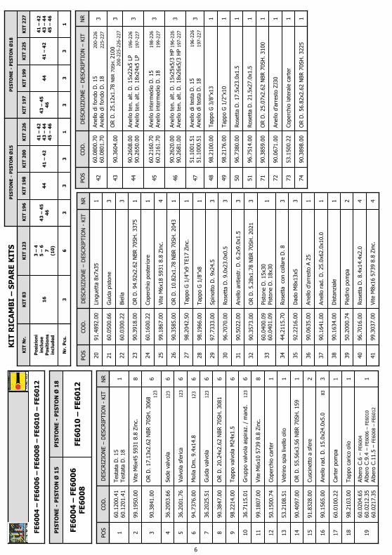
RIC
AM
BI
–S
PA
RE
KIT
S
KIT
Nr.
Po
sizi
on
i in
clu
seP
osi
tio
ns
incl
ud
ed
Nr.
Pcs
.
PIS
TON
E -
PIS
TO
N Ø
15
KIT
14
1
27
–2
83
0 –
31
3
KIT
14
0
27
–2
82
9 –
30
31 1
KIT
96
KIT
86
27
–2
82
9 –
30
31 1
27
-2
82
9 3
PIS
TO
NE
-P
IST
ON
Ø1
8
FE5
10
8
PIS
TO
NE
-P
IST
ON
Ø1
5
FE5
10
1 –
FE5
10
2FE
51
04
–FE
51
06
FE5
10
1 –
FE5
10
2 –
FE5
10
4 -
FE5
10
6 –
FE5
10
8
2

DIS
. CO
D.
51
. 9
57
6.0
0
51
SE
RIE
S –
HX
M V
ALV
E
* F
issa
re c
on
Lo
ctit
e5
42
co
l. R
OS
SO
* A
ffix
wit
h L
oct
ite
54
2 c
ol.
RE
D*
Fix
er a
vec
de
la L
oct
ite
54
2 c
ou
leu
r R
OU
GE
* M
itLo
ctit
e5
42
RO
T b
efes
tig
en*
Fij
ar
con
Lo
ctit
e 5
42
co
l. R
OJO
* F
ixar
co
m L
oct
ite
54
2 c
or.
VE
RM
ELH
A
**
Fis
sare
co
n L
oct
ite
27
0 c
ol.
VE
RD
E*
* A
ffix
wit
h L
oct
ite
27
0 c
ol.
GR
EE
N*
* F
ixer
ave
c d
e la
Lo
ctit
e2
70
co
ule
ur
VE
RT
**
Mit
Loct
ite
27
0 G
RÜ
Nb
efes
tig
en*
* F
ija
r co
n L
oct
ite
27
0 c
ol.
VE
RD
E*
* F
ixar
co
m L
oct
ite
27
0 c
or.
VE
RD
E
3

3Ros
etta
D.
9.0x
23.0
x0.5
96.7
070.
0021
1Li
ngue
tta
8x7x2
5 U
NI
6604
91.4
877.
0019
3Ane
llo r
ad.
D. 15
x24x
5
83
90.1
565.
0020
1
Alb
ero
C.3
.5 -
FE5102
Alb
ero
C.6
-FE
510
4
Alb
ero
C.8
-FE
510
8
Alb
ero
C.9
.4 -
FE5106
Alb
ero
C.2
-FE
510
1
51.0
230.
6551
.020
0.65
51.0
201.
6551
.020
4.65
51.0
220.
65
18
4Vite
M6x
10 5
937
8.8
Zin
c.99
.180
7.00
17
1Cop
erch
io c
arte
r50
.150
0.74
16
1Ane
llo r
ad.
D. 25
.0x6
2.0x
10.0
90.1
641.
0015
1Ane
llo d
’arr
esto
A25
90.0
635.
0014
1Sp
ia li
vello
olio
97.5
968.
005
3G
uida
pis
tone
51.0
500.
566
3Sp
inot
to D
. 8x
24.5
97.7
310.
008
1O
R D
. 88
.57x
2.62
NBR
70S
H.
3350
90.3
917.
009
1Cop
erch
io p
oste
rior
e51
.160
0.22
10
4Vite
M6x
18 5
931
8.8
Zin
c.99
.186
7.00
11
1Tap
po c
aric
o ol
io98
.210
3.00
12
3Bie
lla51
.030
1.22
7
1Cus
cine
tto a
sfe
re91
.832
8.00
13
1Boc
cola
a r
ullin
i91
.801
4.00
4
DES
CR
IZIO
NE –
DES
CRIP
TIO
N -
KIT
Car
ter
pom
pa
Tap
po G
3/8
”x13
TE2
2 Zi
nc.
OR D
. 13
.95x
2.62
NBR
70S
H.
3056
NR 1 1 2
CO
D.
51.0
106.
22
98.2
100.
50
90.3
833.
00
POS
1 2 3
6M
olla
Dm
. 9.
4x1
4.8
1
2394
.737
6.00
38
6G
uida
val
vola
123
36.2
025.
5139
6Val
vola
sfe
rica
123
36.2
001.
7637
6Se
de v
alvo
la
123
36.2
003.
6636
6O
R D
. 17
.13x
2.62
NBR
70S
H.
3068
123
90.3
841.
0035
3Pi
ston
e D
. 15
x25
Pist
one
D. 18
x25
51.0
400.
0951
.040
1.09
24
3O
R D
. 5.
28x1
.78
NBR 7
0SH
. 20
2190
.357
3.00
23
3Ane
llo a
ntie
st.
D. 6.2
x9.0
x1.5
90.5
022.
0022
3Ros
etta
con
col
lare
D. 8
44.2
115.
7025
3D
ado
M8x
13x5
–IN
OX
92.2
216.
0026
3
OR D
. 15
.08x
2.62
NBR
70S
H.
119
86-
96
OR D
. 17
.86x
2.62
NBR
70S
H.
123 13
9-140
90.3
835.
00
90.3
843.
0027
3O
R D
. 25
.12x
1.78
NBR
70S
H.
2100
86-9
6-97-
139-
140-
141
90.3
604.
0028
8Vite
M6x
40 5
931
8.8
Zin
c.99
.194
3.00
33
1Tes
tata
D. 15
con
val
vola
Tes
tata
D. 18
con
val
vola
51.1
201.
4151
.120
5.41
32
3Ane
llo d
i tes
ta D
. 15
9
6-97
Ane
llo d
i tes
ta D
. 18
140
-141
51.1
000.
5151
.100
1.51
31
3Ane
llo t
en.
alt.
D.
15x2
5x5/
3.1
96-
97
Ane
llo t
en.
alt.
D.
18x2
6x5/
3
1
40-1
41
90.2
620.
0090
.268
1.00
30
3Ane
llo d
i fon
do D
. 15
86-9
6-97
Ane
llo d
i fon
do D
. 18
1
39-
140-1
41
51.0
800.
7051
.080
3.70
29
8Ron
della
D. 6.
4x1
0.0x
0.7
96.6
938.
0034
NR
DES
CR
IZIO
NE –
DES
CRIP
TIO
N -
KIT
CO
D.
POS
1Tap
po G
3/8
”x13
98.2
100.
0064
1Pr
otez
ione
51.2
090.
5162
1Po
mol
o
2
67
36.0
054.
7061
1Vite
M4X
4 59
23 8
.8 Z
inc.
2
67
99.1
261.
0063
1M
olla
Dm
. 11
.8x2
8.5
26
794
.740
0.00
60
1Pi
ston
cino
di c
oman
do
267
36.3
237.
7057
1Ane
llo a
ntie
str.
D. 5.
2x8.0
x1.5
267
90.5
020.
0056
1O
R D
. 4.
48x1
.78
NBR 7
0SH
. 20
1826
790
.357
0.00
55
1O
R D
. 3.
69x1
.78
NBR 7
0SH
. 20
1526
790
.356
9.00
54
1Ane
llo a
ntie
st.
D. 4.0
x6.8
x1.5
267
90.5
007.
0053
6Tap
po M
24x1
.5x1
1.2
157
98.2
216.
0041
7O
R D
. 20
.24x
2.62
NBR
70S
H.
3081
157
-26
790
.384
7.00
40
6G
ruppo
val
vola
asp
iraz
. /
man
d.
12
336
.711
5.01
42
1O
R D
. 9.
92x2
.62
NBR 7
0SH
. 11
2 2
67
90.3
823.
0047
1Ros
etta
D.
17.5
x23x
1.5
96.7
380.
0046
1Tap
po M
14x9
98.2
057.
0045
2Tap
po G
1/4
”x9
98.2
041.
0044
1N
ippl
oD
. 3x
G 3
/8”
10.0
078.
7043
1Boc
cola
267
36.0
055.
7052
1Val
vola
26
736
.323
9.66
51
1Se
de v
alvo
la
267
10.0
085.
6650
1O
R D
. 6.
75x1
.78
NBR 7
0SH
. 10
6
67
90.3
576.
0049
1D
ista
nzia
le s
ede
valv
ola
267
36.0
056.
7048
NR
DES
CR
IZIO
NE –
DES
CRIP
TIO
N -
KIT
CO
D.
POS
PIS
TO
NE
-P
IST
ON
Ø1
8
FE5
10
8
PIS
TO
NE
-P
IST
ON
Ø1
5
FE5
10
1 –
FE5
10
2FE
51
04
–FE
51
06
FE5
10
1 –
FE5
10
2 –
FE5
10
4 -
FE5
10
6 –
FE5
10
8
KIT
15
7
40
–4
1
6
KIT
13
9
27
-2
82
9 3
KIT
97
28
–2
93
0 –
31
3
PIS
TON
E -
PIS
TO
N Ø
18
KIT
83
20 3
KIT
12
3
35
–3
63
7 –
38
39
(42
)
6
KIT
26
7
40
-4
7 –
48
–4
95
0 -
51
–5
2 –
53
54
-5
5 -
56
–5
76
0 -
61
–6
3
1
KIT
RIC
AM
BI
–S
PA
RE
KIT
S
KIT
Nr.
Po
sizi
on
i in
clu
seP
osi
tio
ns
incl
ud
ed
Nr.
Pcs
.
PIS
TON
E -
PIS
TO
N Ø
15
KIT
14
1
28
–2
93
0 –
31
3
KIT
14
0
27
–2
82
9 –
30
31 1
KIT
96
KIT
86
27
–2
82
9 –
30
31 1
27
-2
82
9 3
4

DIS
. CO
D.
60
95
00
.00
60
SE
RIE
S
* F
issa
re c
on
Lo
ctit
e5
42
co
l. R
OS
SO
*
Aff
ix w
ith
Lo
ctit
e5
42
co
l. R
ED
* F
ixer
ave
c d
e la
Lo
ctit
e5
42
co
ule
ur
RO
UG
E *
Mit
Loct
ite
54
2 R
OT
bef
esti
gen
* F
ija
r co
n L
oct
ite
54
2 c
ol.
RO
JO
*
Fix
ar c
om
Lo
ctit
e 5
42
co
r. V
ER
ME
LHA
**
Fis
sare
co
n L
oct
ite
27
0 c
ol.
VE
RD
E*
* A
ffix
wit
h L
oct
ite
27
0 c
ol.
GR
EE
N*
* F
ixer
ave
c d
e la
Lo
ctit
e2
70
co
ule
ur
VE
RT
**
Mit
Loct
ite
27
0 G
RÜ
Nb
efes
tig
en*
* F
ija
r co
n L
oct
ite
27
0 c
ol.
VE
RD
E*
* F
ixar
co
m L
oct
ite
27
0 c
or.
VE
RD
E
5
1Alb
ero
C.6
–FE
6004
Alb
ero
C.9
.4 –
FE60
06 –
FE60
10
Alb
ero
C.1
1.5
–FE
6008
–FE
6012
60.0
204.
6560
.021
2.35
60.0
217.
3519
1Tap
po c
aric
o ol
io98
.210
3.00
18
1Car
ter
pom
pa60
.010
0.22
17
3Ane
llo r
ad.
D. 15
.0x2
4.0x
5.0
8
390
.156
5.00
16
2Cus
cine
tto a
sfe
re91
.832
8.00
15
1O
R D
. 55
.56x
3.56
NBR
70S
H.
159
90.4
097.
0014
1Vet
rino
spi
a liv
ello
olio
53.2
108.
5113
1Cop
erch
io c
arte
r50
.150
0.74
12
6G
ruppo
val
vola
asp
iraz
. /
man
d.
1
2336
.711
5.01
10
8Vite
M6x
10 5
739
8.8
Zin
c.99
.180
7.00
11
6Tap
po v
alvo
la M
24x1
.598
.221
4.00
9
6O
R D
. 20
.24x
2.62
NBR
70S
H.
3081
90.3
847.
008
6G
uida
val
vola
123
36.2
025.
517
6M
olla
Dm
. 9.
4x1
4.8
123
94.7
376.
006
6Val
vola
sfe
rica
1
2336
.200
1.76
5
6Se
de v
alvo
la
123
36.2
003.
664
6O
R D
. 17
.13x
2.62
NBR
70S
H.
3068
123
90.3
841.
003
8Vite
M6x
45 5
931
8.8
Zin
c.99
.195
0.00
2
DES
CR
IZIO
NE –
DES
CRIP
TIO
N -
KIT
Tes
tata
D. 15
Tes
tata
D. 18
NR 1
CO
D.
60.1
200.
4160
.120
1.41
POS
1
1D
ista
nzia
le90
.163
4.00
38
3G
uida
pis
tone
60.0
500.
6621
4Vite
M8x
16 5
739
8.8
Zin
c.99
.303
7.00
41
4Ros
etta
D.
8.4x
14.4
x2.0
96.7
016.
0040
2Pi
edin
o po
mpa
50.2
000.
7439
1Pi
ston
e D
. 15
x30
Pist
one
D. 18
x30
60.0
400.
0960
.040
1.09
33
3O
R D
. 5.
28x1
.78
NBR 7
0SH
. 20
2190
.357
3.00
32
3Ane
llo a
ntie
str.
D. 6.
2x9.0
x1.5
90.5
022.
0031
3Ros
etta
D.
9.0x
23.0
x0.5
96.7
070.
0030
3Sp
inot
to D
. 9x
24.5
97.7
333.
0029
1Tap
po G
1/8
”x8
98.1
966.
0028
1Tap
po G
1/4
”x9
TE1
7 Zi
nc.
98.2
042.
5027
1O
R D
. 10
.82x
1.78
NBR
70S
H.
2043
90.3
585.
0026
4Vite
M6x
18 5
931
8.8
Zin
c.99
.186
7.00
25
1Cop
erch
io p
oste
rior
e60
.160
0.22
24
1O
R D
. 94
.92x
2.62
NBR
70S
H.
3375
90.3
918.
0023
3Bie
lla60
.030
0.22
22
3D
ado
M8x
13x5
92.2
216.
0035
3Ros
etta
co
n c
olla
re D
. 8
44.2
115.
7034
1Li
ngue
tta
8x7x3
591
.489
2.00
20
1Ane
llo d
’arr
esto
A 2
590
.063
5.00
36
1Ane
llo r
ad.
D. 25
.0x6
2.0x
10.0
90.1
641.
0037
NR
DES
CR
IZIO
NE –
DES
CRIP
TIO
N -
KIT
CO
D.
POS
1O
R D
. 56
.82x
2.62
NBR
70S
H.
3225
90.3
898.
0074
1Cop
erch
io la
tera
le c
arte
r53
.150
0.22
73
1Ane
llo d
’arr
esto
ZJ3
090
.067
1.00
72
1O
R D
. 25
.07x
2.62
NBR
70S
H.
3100
90.3
859.
0071
3O
R D
. 25
.12x
1.78
NBR 7
0SH
. 21
00200-
225-
226
-227
90.3
604.
0043
3Ane
llo t
en.
alt.
D.
15x2
2x5
LP
19
6-226
Ane
llo t
en.
alt.
D.
18x2
4x5
LP
19
7-227
90.2
608.
0090
.265
0.00
44
1Ros
etta
D.
21.5
x27.
0x1.
596
.751
4.00
51
1Ros
etta
D.
17.5
x23.
0x1.
596
.738
0.00
50
1Tap
po G
1/2
”x10
98.2
176.
0049
1Tap
po G
3/8
”x13
98.2
100.
0048
3Ane
llo d
i tes
ta D
. 15
196
-226
Ane
llo d
i tes
ta D
. 18
197
-227
51.1
001.
5151
.100
0.51
47
3Ane
llo t
en.
alt.
D.
15x2
5x5/
3 H
P196
-226
Ane
llo t
en.
alt.
D.
18x2
6x5/
3 H
P 197
-227
90.2
620.
0090
.268
1.00
46
3Ane
llo in
term
edio
D. 15
198-2
26
Ane
llo in
term
edio
D. 18
199-2
27
60.2
160.
7060
.216
1.70
45
3Ane
llo d
i fon
do D
. 15
200-
226
Ane
llo d
i fon
do D
. 18
225-
227
60.0
800.
7060
.080
1.70
42
NR
DES
CR
IZIO
NE –
DES
CRIP
TIO
N –
KIT
CO
D.
POS
PIS
TO
NE
-P
IST
ON
Ø1
8
FE6
01
0 –
FE6
01
2
PIS
TO
NE
-P
IST
ON
Ø1
5
FE6
00
4 –
FE6
00
6FE
60
08
FE6
00
4 –
FE6
00
6 –
FE6
00
8 –
FE6
01
0 –
FE6
01
2
KIT
19
9
44 3
KIT
20
0
41
–4
2
3
KIT
19
7
43
–4
54
6 3
KIT
22
6
41
–4
24
3 –
44
45
–4
6
1
PIS
TON
E -
PIS
TO
N Ø
18
KIT
83
16 3
KIT
12
3
3 –
45
–6
7(1
0)
6
KIT
RIC
AM
BI
–S
PA
RE
KIT
S
KIT
Nr.
Po
sizi
on
i in
clu
seP
osi
tio
ns
incl
ud
ed
Nr.
Pcs
.
PIS
TON
E -
PIS
TO
N Ø
15
KIT
22
7
41
–4
24
3 –
44
45
–4
6
1
KIT
22
5
41
–4
2
3
KIT
19
8K
IT 1
96
44 3
43
–4
54
6 3
6

DIS
. CO
D.
60
. 9
51
1.0
06
0 S
ER
IES
–H
XM
VA
LVE
* F
issa
re c
on
Lo
ctit
e5
42
co
l. R
OS
SO
* A
ffix
wit
h L
oct
ite
54
2 c
ol.
RE
D*
Fix
er a
vec
de
la L
oct
ite
54
2 c
ou
leu
r R
OU
GE
* M
itLo
ctit
e5
42
RO
T b
efes
tig
en*
Fij
ar
con
Lo
ctit
e 5
42
co
l. R
OJO
*Fi
xar
co
m L
oct
ite
54
2 c
or.
VE
RM
ELH
A
**
Fis
sare
co
n L
oct
ite
27
0 c
ol.
VE
RD
E*
* A
ffix
wit
h L
oct
ite
27
0 c
ol.
GR
EE
N*
* F
ixer
ave
c d
e la
Lo
ctit
e2
70
co
ule
ur
VE
RT
**
Mit
Loct
ite
27
0 G
RÜ
Nb
efes
tig
en*
* F
ija
r co
n L
oct
ite
27
0 c
ol.
VE
RD
E*
* F
ixar
co
m L
oct
ite
27
0 c
or.
VE
RD
E
7

3O
R D
. 5.
28x1
.78
NBR 7
0SH
. 20
2190
.357
3.00
23
3Ane
llo a
ntie
str.
D. 6.
2x9.0
x1.5
90.5
022.
0022
3Ros
etta
D.
9.0x
23.0
x0.5
96.7
070.
0021
1Li
ngue
tta
8x7x3
591
.489
2.00
19
3Ane
llo r
ad.
D. 15
.0x2
4.0x
5.0
8
390
.156
5.00
20
1Alb
ero
C.6
–
FE60
04
Alb
ero
C.9
.4 –
FE600
6 –
FE601
0
Alb
ero
C.1
1.5
–FE
6008
–FE
6012
60.0
204.
6560
.021
2.35
60.0
217.
3518
1Ane
llo r
ad.
D. 25
.0x6
2.0x
10.0
90.1
641.
0017
1Ane
llo d
’arr
esto
A25
90.0
635.
0016
1Tap
po c
aric
o ol
io98
.210
3.00
15
4Vite
M6x
18 5
931
8.8
Zin
c.99
.186
7.00
14
1Cop
erch
io c
arte
r50
.150
0.74
5
8Vite
M6x
10 5
739
8.8
Zin
c.99
.180
7.00
6
3Bie
lla60
.030
0.22
8
3Sp
inot
to D
. 9x
24.5
97.7
333.
009
1O
R D
. 94
.92x
2.62
NBR
70S
H.
3375
90.3
918.
0010
1Cop
erch
io p
oste
rior
e ca
rter
60.1
600.
2211
1O
R D
. 10
.82x
1.78
NBR
70S
H.
2043
90.3
585.
0012
3G
uida
pis
tone
60.0
500.
667
1Tap
po G
1/4
”x9
TE1
7 Zi
nc.
98.2
042.
5013
1Vet
rino
spi
a liv
ello
olio
53.2
108.
514
DES
CR
IZIO
NE –
DES
CRIP
TIO
N -
KIT
Car
ter
pom
pa
Cus
cine
tto a
sfe
re
OR D
. 56
.82x
2.62
NBR
70S
H.
3225
NR 1 2 1
CO
D.
60.0
100.
22
91.8
328.
00
90.3
898.
00
POS
1 2 3
1Tap
po G
1/8
”x8
98.1
966.
0045
1N
ippl
oD
. 3x
G 3
/8”
10.0
078.
7044
1O
R D
. 13
.95x
2.62
NBR
70S
H.
3056
90.3
833.
0043
6G
ruppo
val
vola
asp
iraz
. /
man
d.
123
36.7
115.
0142
6Tap
po v
alvo
la M
24x1
.598
.221
4.00
41
6M
olla
Dm
. 9.
4x1
4.8
1
2394
.737
6.00
38
7O
R D
. 20
.24x
2.62
NBR
70S
H.
3081
267
90.3
847.
0040
6G
uida
val
vola
123
36.2
025.
5139
6Val
vola
sfe
rica
123
36.2
001.
7637
6Se
de v
alvo
la
123
36.2
003.
6636
6O
R D
. 17
.13x
2.62
NBR
70S
H.
3068
123
90.3
841.
0035
1Pi
ston
e D
. 15
x30
Pist
one
D. 18
x30
60.0
400.
0960
.040
1.09
24
3Ros
etta
con
col
lare
D. 8
44.2
115.
7025
3D
ado
M8x
13x5
92.2
216.
0026
3Ane
llo d
i fon
do D
. 15
200
-226
Ane
llo d
i fon
do D
. 18
225
-227
60.0
800.
7060
.080
1.70
27
3O
R D
. 25
.12x
1.78
NBR 7
0SH
. 21
0020
0-22
5-226
-227
90.3
604.
0028
1Tes
tata
D. 15
con
val
vola
Tes
tata
D. 18
con
val
vola
60.1
204.
4160
.120
5.41
33
3Ane
llo d
i tes
ta D
. 15
196
-226
Ane
llo d
i tes
ta D
. 18
197
-227
51.1
001.
5151
.100
0.51
32
3Ane
llo t
en.
alt.
D.
15x2
5x5/
3 H
P196
-226
Ane
llo t
en.
alt.
D.
18x2
6x5/
3 H
P 197
-227
90.2
620.
0090
.268
1.00
31
3Ane
llo in
term
edio
D. 15
198-2
26
Ane
llo in
term
edio
D. 18
199-2
27
60.2
160.
7060
.216
1.70
30
3Ane
llo t
en.
alt.
D.
15x2
2x5
LP
19
6-226
Ane
llo t
en.
alt.
D.
18x2
4x5
LP
19
7-227
90.2
608.
0090
.265
0.00
29
8Vite
M6x
45 5
931
8.8
Zin
c.99
.195
0.00
34
NR
DES
CR
IZIO
NE –
DES
CRIP
TIO
N -
KIT
CO
D.
POS
1Cop
erch
io la
tera
le c
arte
r53
.150
0.22
70
1Ane
llo d
’arr
esto
ZJ3
090
.067
1.00
69
1O
R D
. 25
.07x
2.62
NBR
70S
H.
3100
90
.385
9.00
68
4Vite
M8x
16 5
739
8.8
Zin
c.99
.303
7.00
67
1Vite
M4x
4 59
23 8
.8 Z
inc.
2
67
99.1
261.
0063
1M
olla
Dm
. 11
.8x2
8.5
26
794
.740
0.00
62
4Ron
della
D. 8.
4x1
4.4x
2.0
96.7
016.
0066
2Pi
edin
o po
mpa
50.2
000.
7465
1Po
mol
o
2
67
36.0
054.
7064
1Pi
ston
cino
di c
oman
do
267
36.3
237.
7061
1Ane
llo a
ntie
st.
D. 5.2
x8.0
x1.5
267
90.5
020.
0060
1O
R D
. 4.
48x1
.78
NBR 7
0SH
. 20
18 2
6790
.357
0.00
59
1O
R D
. 3.
69x1
.78
NBR 7
0SH
. 20
15 2
6790
.356
9.00
58
1Ane
llo a
ntie
st.
D. 4.0
x6.8
x1.5
267
90.5
007.
0057
1Boc
cola
26
736
.005
5.70
56
1Val
vola
2
6736
.323
9.66
55
1Se
de v
alvo
la
267
10.0
085.
6654
1Tap
po G
1/2
”x10
98.2
176.
0048
1Ros
etta
D.
21.5
x27.
0x1.
596
.751
4.00
47
1Tap
po M
14x1
x998
.205
7.00
46
1O
R D
. 6.
75x1
.78
NBR 7
0SH
. 10
6
267
90.3
576.
0053
1D
ista
nzia
le s
ede
valv
ola
267
36.0
056.
7052
1O
R D
. 9.
92x2
.62
NBR 7
0SH
. 11
2
267
90.3
823.
0051
1Tap
po G
3/8
”x13
98.2
100.
0050
1Ros
etta
D.
17.5
x23.
0x1.
596
.738
0.00
49
NR
DES
CR
IZIO
NE –
DES
CRIP
TIO
N -
KIT
CO
D.
POS
PIS
TO
NE
-P
IST
ON
D.
18
FE6
01
0 –
FE6
01
2
PIS
TO
NE
-P
IST
ON
D.
15
FE6
00
4 –
FE6
00
6FE
60
08
FE6
00
4 –
FE6
00
6 –
FE6
00
8 –
FE6
01
0 –
FE6
01
2
KIT
12
3
35
–3
63
7 –
38
39
(42
)
6
KIT
19
9
30 3
KIT
20
0
27
–2
8
3
KIT
19
7
29
–3
13
2 3
KIT
22
6
27
–2
82
9 –
30
31
–3
2
1
PIS
TON
E -
PIS
TO
N Ø
18
KIT
83
20 3
KIT
26
7
40
-5
1 –
52
–5
35
4 -
55
–5
6 –
57
58
-5
9 -
60
–6
16
4 -
65
–6
6
1
KIT
RIC
AM
BI
–S
PA
RE
KIT
SK
IT N
r.
Po
sizi
on
i in
clu
seP
osi
tio
ns
incl
ud
ed
Nr.
Pcs
.
PIS
TON
E -
PIS
TO
N Ø
15
KIT
22
7
27
–2
82
9 –
30
31
–3
2
1
KIT
22
5
27
–2
8
3
KIT
19
8K
IT 1
96
30 3
29
–3
13
2 3
8

FE5101 – FE5102FE5104 – FE5106
FE5108COD. DIS. 51.2145.00
COD. DIS. 51.9609.00
STD. VERSION
FE5101 – FE5102FE5104 – FE5106
FE5108
HXM VERSION
DIMENSIONI D’INGOMBRO – OVERALL DIMENSIONS – DIMENSIONS D’ENCOMBREMENTRAUMBEDARF – DIMENSIONES TOTALES – DIMENSÕES
9

FE6004 - FE6006 - FE6008FE6010 - FE6012
COD. DIS. 60.9623.00
STD. VERSION
COD. DIS. 60.9600.00
FE6004 - FE6006 - FE6008FE6010 - FE6012
HXM VERSION
DIMENSIONI D’INGOMBRO – OVERALL DIMENSIONS – DIMENSIONS D’ENCOMBREMENTRAUMBEDARF – DIMENSIONES TOTALES – DIMENSÕES
10

1 - CHANGEMENT DE L’HUILE
1.1 – Le changement de l’huile doit être exécuté avec la pompe à température d’exercice.
1.2 – Placer un récipient sous le bouchon de vidange de l’huile (3).
1.3 – Enlever le bouchon-jauge (1), puis enlever le bouchon de vidange (3).
1.4 – Attendre que toute l’huile soit sortie, puis revisser le bouchon de vidange (3) avec le couple de torsion qui est indiqué sur le dessin éclaté.
1.5 – Remplir avec de l’huile neuve jusqu’à la ligne médiane du bouchon indicateur du niveau d’huile (2), et revisser le bouchon-jauge (1).
Pour le type d’huile à utiliser, se référer à ce qui est indiqué sur la notice générale.
ATTENTION : L’huile usée doit être recueillie dans des récipients et éliminée dans les centres prévus à cet effet, conformément à la réglementation en vigueur. Il ne faut absolument pas la jeter dans l’environnement.
1 – OIL CHANGING
1.1 – Oil changing must be done with the pump at operating temperature.1.2 – Put a container under the oil drain plug (3).
1.3 – Remove the oil dipstick (1) and then the drain plug (3).
1.4 – Wait until all the oil has drained out, then screw the drain plug (3) and tighten at the torque shown in the exploded diagram.
1.5 – Fill with new oil until the middle of the oil level indicator (2) is reached, screw by hand the oil dipstick (1).
Refer to the generic booklet for the type of oil to use.
WARNING: The exhaust oil must be collected in receptacles and disposed of at authorised centres as specified by law. It must not be thrown away in the environment.
1 - CAMBIO OLIO
1.1 – Il cambio dell’olio va eseguito con pompa a temperatura di lavoro.
1.2 – Posizionare un recipiente sotto il tappo di scarico olio (3).
1.3 – Rimuovere il tappo con asta (1) e successivamente il tappo di scarico (3).
1.5 – Riempire con olio nuovo fino al raggiungimento della mezzeria del tappo spia livello olio (2) e riavvitare il tappo con asta (1) .
1.4 – Attendere fino a quando tutto l’olio è uscito, quindi riavvitare il tappo di scarico (3) con la coppia torcente indicata su disegno esploso.
ATTENZIONE: L’olio esausto deve essere raccolto in recipienti e smaltito negli appositi centri in accordo alla normativa vigente. Non deve essere assolutamente disperso nell’ambiente.
Per il tipo di olio da utilizzare fare riferimento a quanto indicato sul libretto generico.
1
2
3
51 SERIES
60 SERIES
1
23
11

1.1 – El cambio de aceite se efectúa con bomba a temperatura de trabajo.
1.2 – Colocar un recipiente debajo del tapón de descarga de aceite (3).
1.3 – Extraer el tapón con varilla (1) y seguidamente el tapón de descarga (3).
1.4 – Esperar hasta que haya salido todo el aceite, volver a enroscar el tapón de descarga (3) con el par de torsión indicado en el despiece.
1.5 – Llenar con aceite nuevo hasta alcanzar la línea media del tapón indicador de nivel de aceite (2) y volver a enroscar el tapón con varilla (1).
Para el tipo de aceite que debe utilizarse, remitirse a las indicaciones del manual general.
ATENCIÓN: El aceite residual debe recogerse en recipientes y eliminarse en los centros pertinentes de acuerdo con la normativa vigente. En ningún caso debe dispersarse en el ambiente.
1.1 – A troca de óleo deve ser feita com a bomba na temperatura de trabalho.
1.2 – Posicionar um recipiente embaixo da tampa de descarga de óleo (3).
1.3 – Remover a tampa com o pino (1) e, em seguida, a tampa de descarga (3).
1.4 – Esperar que todo o óleo saia, recolocar a tampa de descarga (3) com o binário de torção indicado no desenho explodido.
1.5 – Encher com o óleo novo até chegar na linha da tampa de controle do nível do óleo (2) e recolocar a tampa com o pino (1).
Para o tipo de óleo a ser utilizado, consultar as indicações do livro genérico.
ATENÇÃO: O óleo consumido deve ser coletado em recipientes e eliminado nos locais adequados, de acordo com a normativa vigente. Não deve, de modo algum, ser jogado no ambiente.
1 - CAMBIO DE ACEITE
1 - TROCA DE ÓLEO
1 - ÖLWECHSEL
1.1 – Beim Ölwechsel muss die Pumpe Betriebstemperatur aufweisen.
1.2 – Unter den Ölablassverschluss (3) einen Behälter stellen.
1.3 – Den Verschluss mit dem Stab (1) und danach den Ablassverschluss (3) abnehmen.
1.4 – Warten, bis das gesamte Öl abgelassen ist und den Ablassverschluss (3) mit dem auf der Übersichtszeichnung angegebenen Drehmoment wieder anschrauben.
1.5 – Mit frischem Öl füllen, bis die Mittellinie des Ölstandkontrollverschlusses (2) erreicht ist und den Verschlussmit dem Stab (1) wieder anschrauben.
Bezüglich der verwendbaren Ölsorten siehe die Angaben im allgemeinen Handbuch.
ACHTUNG: Das Altöl muss in Behältern gesammelt und gemäß den geltendenVorschriften bei den hierfür vorgesehenen Zentren entsorgt werden. Es darf keinesfallsumweltschädigend entsorgt werden.
12
Dichiarazione di incorporazione(Ai sensi dell’allegato II della Direttiva Europea 2006/42/CE).
Il produttore INTERPUMP GROUP S.p.A. – Via E. Fermi, 25 – 42049 S.ILARIO D’ENZA (RE) - Italia
DICHIARA sotto la propria esclusiva responsabilità che l’attrezzatura identificata e descritta come segue : Denominazione: Pompa Tipo: Pompa alternativa a pistoni per acqua ad alta pressione
Marchio di fabbrica: INTERPUMP GROUPModello: FE5101 – FE5102 – FE5104 – FE5106 – FE5108 - FE6004 – FE6006 – FE6008 – FE6010 – FE6012
Risulta essere conforme alle sotto elencate direttive e successivi aggiornamenti :- Direttiva Macchine 2006/42/CE- Direttiva sulla restrizione dell’uso di determinate sostanze pericolose nelle apparecchiature elettriche ed
elettroniche 2011/65/UE - RoHS
L’attrezzatura non contiene sostanze con restrizioni d’uso in concentrazione maggiore di quelle elencate
nell’allegato II ad eccezione delle applicazioni esentate dalle restrizioni elencate nell’allegato III.
Norme applicate : UNI EN ISO 12100:2010 - UNI EN 809:2000
Firma ________________
La pompa sopra identificata rispetta i seguenti requisiti essenziali di sicurezza e di tutela della salute elencati nel punto 1 dell’allegato I della Direttiva Macchine :1.1.2 - 1.1.3 - 1.1.5 - 1.3.1 - 1.3.2 - 1.3.3 - 1.3.4 - 1.5.4 - 1.5.5 - 1.6.1 - 1.7.1 - 1.7.2 - 1.7.4 - 1.7.4.1 - 1.7.4.2e la relativa documentazione tecnica è stata compilata in conformità dell’allegato VII B.
Inoltre il produttore si impegna a rendere disponibile, a seguito di una richiesta adeguatamente motivata, copia della documentazione tecnica pertinente la pompa nei modi e nei termini da definire.
La pompa non deve essere messa in servizio finché l’impianto al quale la pompa deve essere incorporata èstato dichiarato conforme alle disposizioni delle relative direttive e/o norme.
Persona autorizzata a costituire il fascicolo tecnico : Nome: Maurizio Novelli
Persona autorizzata a redigere la dichiarazione : L’amministratore delegato Ing. Paolo Marinsek
Reggio Emilia 02/2013
Indirizzo: INTERPUMP GROUP S.p.A. – Via E. Fermi, 25 – 42049 S. ILARIO D’ENZA (RE) – Italia
13

Declaration of incorporation(In accordance with Annex II of European Directive 2006/42/CE).
The manufacturer INTERPUMP GROUP S.p.A. – Via E. Fermi, 25 – 42049 S.ILARIO D’ENZA (RE) - ItalyDECLARES under sole responsibility that the equipment identified and described as follows : Name: PumpType: Reciprocating plunger pump for high pressure waterTrademark: INTERPUMP GROUPModel: FE5101 – FE5102 – FE5104 – FE5106 – FE5108 - FE6004 – FE6006 – FE6008 – FE6010 – FE6012
Complies with the requirements of the directives listed below and subsequent updates :- Machinery Directive 2006/42/CE- Directive 2011/65/EU – RoHS on the restriction of the use of certain hazardous substances in electrical
and electronic equipment.
The equipment does not contain more than the specified concentrations of restricted substances listed in Annex II except for the applications exempted from the restriction listed in Annex III.
Standards applied : UNI EN ISO 12100:2010 - UNI EN 809:2000
Signature ________________
The pump identified above meets all the essential safety and health protection requirements as listed in section 1 of Annex I of the Machinery Directive :1.1.2 - 1.1.3 - 1.1.5 - 1.3.1 - 1.3.2 - 1.3.3 - 1.3.4 - 1.5.4 - 1.5.5 - 1.6.1 - 1.7.1 - 1.7.2 - 1.7.4 - 1.7.4.1 - 1.7.4.2and the relevant technical documentation has been compiled in accordance with Annex VII B.
In addition, the manufacturer undertakes to make available, following a reasoned request, a copy of the relevant technical pump documentation in the manner and terms to be defined.
The pump should not be put into service until the plant to which the pump is to be incorporated has been declared in accordance with the provisions of the relevant directives and/or standards.
Person authorised to compile the technical file : Name: Maurizio Novelli
Person authorized to draw up the declaration : CEO Mr. Paolo Marinsek
Reggio Emilia 02/2013
Address: INTERPUMP GROUP S.p.A. – Via E. Fermi, 25 – 42049 S. ILARIO D’ENZA (RE) – Italy
14

Déclaration d’incorporation(Conformément à l’annexe II de la Directive Européenne 2006/42/CE).
Le fabricant INTERPUMP GROUP S.p.A. – Via E. Fermi, 25 – 42049 S.ILARIO D’ENZA (RE) - ItalieDÉCLARE sous sa seule responsabilité que l'équipement identifié et décrit comme suit : Description: PompeType: Pompe alternative à pistons pour eau à haute pressionMarque de fabrique: INTERPUMP GROUPModèle: FE5101 – FE5102 – FE5104 – FE5106 – FE5108 - FE6004 – FE6006 – FE6008 – FE6010 – FE6012
Est conforme aux spécifications des directives énumérées ci-dessous et mises à jour suivantes:- Directive Machines 2006/42/CE- Directive relative à la limitation de l'utilisation de certaines substances dangereuses dans les équipements
électriques et électroniques 2011/65/UE – RoHS
L'équipement ne contient pas de substances assorties de restrictions concernant l'utilisation en concentration plus élevée que celles énumérées à l'annexe II, sauf pour des applications exemptées des restrictions énumérées à l'annexe III.
Normes appliquées : UNI EN ISO 12100:2010 - UNI EN 809:2000
Signature ________________
La pompe identifiée ci-dessus répond aux exigences essentielles de sécurité et protection de la santé suivantes énumérées au point 1 de l'annexe I de la Directive Machines :1.1.2 - 1.1.3 - 1.1.5 - 1.3.1 - 1.3.2 - 1.3.3 - 1.3.4 - 1.5.4 - 1.5.5 - 1.6.1 - 1.7.1 - 1.7.2 - 1.7.4 - 1.7.4.1 - 1.7.4.2et la documentation technique pertinente est constituée conformément à l'annexe VII B.
De plus, le fabricant s’engage à rendre disponible, suite à une demande adéquatement motivée, une copie de la documentation technique relative à la pompe dans les modes et les termes à définir.
La pompe ne doit pas être mise en marche tant que l’installation à laquelle la pompe doit être incorporée n’a pas été déclarée conforme aux dispositions des directives et / ou normes relatives.
Personne autorisée à réaliser le manuel technique : Nom : Maurizio Novelli
Personne autorisée à rédiger la déclaration : L’administrateur délégué Ing. Paolo Marinsek
Reggio Emilia 02/2013
Adresse: INTERPUMP GROUP S.p.A. – Via E. Fermi, 25 – 42049 S. ILARIO D’ENZA (RE) – Italie
15

Einbauerklärung(gemäß Anhang II der Europäischen Richtlinie 2006/42/EG).
Der Hersteller INTERPUMP GROUP S.p.A. – Via E. Fermi, 25 – 42049 S.ILARIO D’ENZA (RE) - ItalienERKLÄRT auf alleinige Verantwortung, dass das wie folgt bezeichnete und beschriebene Gerät : Bezeichnunge: PumpeTyp: Kolbenpumpe für Hochdruck-WasserHerstellermarke: INTERPUMP GROUPModell: FE5101 – FE5102 – FE5104 – FE5106 – FE5108 - FE6004 – FE6006 – FE6008 – FE6010 – FE6012
mit den nachstehend aufgelisteten Richtlinien und ihren nachfolgenden Aktualisierungen konform ist :- Maschinenrichtlinie 2006/42/EG- Richtlinie zur Beschränkung der Verwendung bestimmter gefährlicher Stoffe in Elektro- und
Elektronikgeräten 2011/65/EU – RoHS
Das Gerät enthält keine Stoffe, für die Beschränkungen bezüglich ihrer Verwendung in Konzentrationen bestehen, die über denen im Anhang II liegen, mit Ausnahme von Anwendungen, die von den im Anhang II aufgeführten Beschränkungen ausgenommen sind.
Angewandte Normen : UNI EN ISO 12100:2010 - UNI EN 809:2000
Unterschrift ________________
Die oben genannte Pumpe genügt den folgenden grundlegenden Sicherheits- und Gesundheitsschutzanforderungen, die unter Punkt 1 des Anhangs I der Maschinenrichtlinie aufgeführt sind.1.1.2 - 1.1.3 - 1.1.5 - 1.3.1 - 1.3.2 - 1.3.3 - 1.3.4 - 1.5.4 - 1.5.5 - 1.6.1 - 1.7.1 - 1.7.2 - 1.7.4 - 1.7.4.1 - 1.7.4.2Die speziellen technischen Unterlagen wurden gemäß Anhang VII Teil B erstellt.
Darüber hinaus verpflichtet sich der Hersteller einzelstaatlichen Stellen auf begründetes Verlangen die speziellen technischen Unterlagen zur Pumpe in festzulegenden Modalitäten und Fristen zu übermitteln.
Die Pumpe darf erst dann in Betrieb genommen werden, wenn gegebenenfalls festgestellt wurde, dass die Maschine, in die die Pumpe eingebaut werden soll, den Bestimmungen der entsprechenden Richtlinien und/oder Normen entspricht .
Person, die bevollmächtigt ist, die relevanten technischen Unterlagen zusammenzustellen: Maurizio Novelli
Person, die zur Ausstellung dieser Erklärung bevollmächtigt ist: Der Geschäftsführer Ing. Paolo Marinsek
Reggio Emilia 02/2013
Adresse: INTERPUMP GROUP S.p.A. – Via E. Fermi, 25 – 42049 S. ILARIO D’ENZA (RE) – Italien
16

Declaración de incorporación(De acuerdo con el anexo II de la Directiva Europea 2006/42/CE).
El fabricante INTERPUMP GROUP S.p.A. – Via E. Fermi, 25 – 42049 S.ILARIO D’ENZA (RE) – Italia DECLARA bajo su propia y exclusiva responsabilidad al aparato identificado y descrito del siguiente modo : Denominación: BombaTipo: Bomba alternativa con pistones para agua de alta presiónMarca de fábrica: INTERPUMP GROUPModelo: FE5101 – FE5102 – FE5104 – FE5106 – FE5108 - FE6004 – FE6006 – FE6008 – FE6010 – FE6012
Resulta ser conforme con las directivas que se indican a continuación y con sus sucesivas actualizaciones:- Directiva de Máquinas 2006/42/CE- Directiva acerca de la restricción del uso de determinadas sustancias peligrosas en máquinas eléctricas y
electrónicas 2011/65/UE – RoHS
El aparato no contiene sustancias con restricción de uso en concentración mayor de aquellas citadas en el anexo II, exceptuando las aplicaciones exentes de las restricciones citadas en el anexo III.
Normas aplicadas : UNI EN ISO 12100:2010 - UNI EN 809:2000
Firma ________________
La bomba identificada anteriormente respeta los siguientes requisitos esenciales de seguridad y de protección de la salud citados en el punto 1 del anexo I de la Directiva de Máquina :1.1.2 - 1.1.3 - 1.1.5 - 1.3.1 - 1.3.2 - 1.3.3 - 1.3.4 - 1.5.4 - 1.5.5 - 1.6.1 - 1.7.1 - 1.7.2 - 1.7.4 - 1.7.4.1 - 1.7.4.2y la correspondiente documentación técnica ha sido compilada de acuerdo con el anexo VII B.
Además el fabricante se compromete en hacer disponible, después haberse llevado a cabo una solicitud adecuadamente motivada, una copia de la documentación técnica pertinente de la bomba en una modalidad y en un plazo aún por definir.
La bomba no debe ser puesta en funcionamiento, hasta que el sistema al cuál la bomba debe ser incorporada, haya sido declarado conforme a las disposiciones de las respectivas directivas y/o normativas.
Persona autorizada a realizar el fascículo técnico : Nombre: Maurizio Novelli
Persona autorizada a redactar la declaración : El administrador delegado Ing. Paolo Marinsek
Reggio Emilia 02/2013
Dirección: INTERPUMP GROUP S.p.A. – Via E. Fermi, 25 – 42049 S. ILARIO D’ENZA (RE) – Italia
17

O fabricante INTERPUMP GROUP S.p.A. – Via E. Fermi, 25 – 42049 S.ILARIO D’ENZA (RE) - ItáliaDECLARA sob a sua exclusiva responsabilidade que os equipamentos identificados e descritos tal como se segue : Denominação: BombaTipo: Bomba alternativa com pistões para água a alta pressãoMarca de fábrica: INTERPUMP GROUPModelo: FE5101 – FE5102 – FE5104 – FE5106 – FE5108 - FE6004 – FE6006 – FE6008 – FE6010 – FE6012
Está em conformidade às directivas abaixo indicadas e posteriores actualizações :- Directiva Máquinas 2006/42/CE- Directiva sobre a restrição de uso de determinadas substâncias perigosas em aparelhos eléctricos e
electrónicos 2011/65/UE – RoHS
O equipamento não contém substâncias com restrições de uso em concentração superior às indicadas noanexo II, á excepção das aplicações isentas das restrições indicadas no anexo III.
Normas aplicadas : UNI EN ISO 12100:2010 - UNI EN 809:2000
Assinatura ________________
A bomba acima identificada respeita os seguintes requisitos essenciais de segurança e de tutela da saúde, referidos no ponto 1 do anexo I da Directiva Máquinas :1.1.2 - 1.1.3 - 1.1.5 - 1.3.1 - 1.3.2 - 1.3.3 - 1.3.4 - 1.5.4 - 1.5.5 - 1.6.1 - 1.7.1 - 1.7.2 - 1.7.4 - 1.7.4.1 - 1.7.4.2e a respectiva documentação técnica foi compilada em conformidade com o anexo VII B.
Além disso, o fabricante compromete-se a disponibilizar, mediante pedido adequadamente motivado, umacópia da documentação técnica referente à bomba, em modos e termos a definir.
A bomba não deve ser colocada em funcionamento até que o sistema no qual tem de ser incorporada seja declarado em conformidade com as disposições das respectivas directivas e/ou normas.
Pessoa autorizada a compilar a documentação técnica : Nome: Maurizio Novelli
Pessoa autorizada a redigir a declaração : O administrador delegado Eng.º Paolo Marinsek
Reggio Emilia 02/2013
Morada: INTERPUMP GROUP S.p.A. – Via E. Fermi, 25 – 42049 S. ILARIO D’ENZA (RE) – Itália
Declaração de incorporação(Nos termos do anexo II da Directiva Europeia 2006/42/CE).
18

CO
D.5
1.2
25
0.0
3 –
07
/15
VIA FERMI, 25 42049 S.ILARIO – REGGIO EMILIA (ITALY) TEL.+39 – 0522 - 904311 TELEFAX +39 – 0522 – 904444E-mail: [email protected] - http://www.interpumpgroup.it
Le informazioni presenti su questo documento possono essere variate senza preavviso.
The information contained in this document may change without notice.
Les informations présentes sur ce document peuvent être changées sans besoin de préavis.
Die in diesem Dokument enthaltenen Informationen können ohne Vorankündigung geändert werden.
La información contenida en el presente documento puede modificarse sin previo aviso.
As informações contidas neste documento poderão ser sujeitas a alterações sem aviso prévio.
COPYRIGHT The contents of this booklet are the property of INTERPUMP GROUP. Reproduction and divulgation, in whole or in part, are prohibited by law.
COPYRIGHT Le contenu de cette notice appartient à INTERPUMP GROUP : aux termes de la loi il est interdit de le reproduire et/ou de le divulguer, même partiellement.
COPYRIGHT Der Inhalt dieser Bedienungsanleitung ist Eigentum von INTERPUMP GROUP. Die auch nur teilweise Reproduktion und/oder Verbreitung ist gesetzlich verboten.
COPYRIGHT El contenido del presente manual es propiedad de INTERPUMP GROUP y está legalmente prohibida su reproducción y/o divulgación parcial o total.
COPYRIGHT Il contenuto di questo libretto è di proprietà di INTERPUMP GROUP, ne è vietata la riproduzione e/o la divulgazione, anche parziale, a termini di legge.
COPYRIGHT O conteúdo deste livro é de propriedade da INTERPUMP GROUP, e é proibida a sua reprodução e/ou a sua divulgação, mesmo parcial, nos termos da lei.
Rev
isio
ne
9
INTERPUMPGROUP