5.1 conventional actuators, shape memory alloys, and
TRANSCRIPT
Invited Chapter in Automation, Miniature Robotics and Sensors for Non-Destructive Testing and Evaluation, Y.Bar-Cohen Editor, April 99
1
5.1 CONVENTIONAL ACTUATORS, SHAPE MEMORY ALLOYS, ANDELECTRORHEOLOGICAL FLUIDS
Constantinos Mavroidis, Charles Pfeiffer and Michael MosleyRobotics and Mechatronics Laboratory
Department of Mechanical and Aerospace EngineeringRutgers University, The State University of New Jersey
98 Brett Rd., Piscataway, NJ [email protected], [email protected], [email protected]
Tel: 732 - 445 – 0732, Fax: 732 - 445 - 3124
5.1 CONVENTIONAL ACTUATORS, SHAPE MEMORY ALLOYS, AND ELECTRORHEOLOGICALFLUIDS ............................................................................................................................................................. 1
5.1.1 INTRODUCTION............................................................................................................................ 15.1.2 CONVENTIONAL ACTUATORS ..................................................................................................... 2
5.1.2.1 Hydraulic Actuators .................................................................................................................................... 25.1.2.1.1 Principle of Operation........................................................................................................................... 25.1.2.1.2 Advantages - Disadvantages.................................................................................................................. 3
5.1.2.2 Pneumatic Actuators ................................................................................................................................... 45.1.2.2.1 Principle of Operation........................................................................................................................... 45.1.2.2.2 Advantages - Disadvantages.................................................................................................................. 5
5.1.2.3 Electric Actuators........................................................................................................................................ 65.1.2.3.1 Principle of Operation........................................................................................................................... 65.1.2.3.2 Advantages - Disadvantages.................................................................................................................. 8
5.1.3 SHAPE MEMORY ALLOY ACTUATORS....................................................................................... 105.1.3.1 History of SMA......................................................................................................................................... 105.1.3.2 Principle of Operation ............................................................................................................................... 105.1.3.3 Nickel-Titanium (Ni-Ti) Shape Memory Alloy........................................................................................... 135.1.3.4 Shape Memory Alloy Actuators in Robotic Applications............................................................................ 145.1.3.5 Modeling, Dynamics, and Control of Shape Memory Alloy Actuators ........................................................ 19
5.1.4 ELECTRO-RHEOLOGICAL FLUIDS (ERF) ................................................................................. 225.1.5 REFERENCES .............................................................................................................................. 24
5.1.1 INTRODUCTION
Robots, being an evolution of machines and mechanisms, originated by the ancientGreeks, Alexandrian and Roman engineers [Dimarogonas, 1993]. The first machines weresimple jointed mechanisms that were actuated by human operators. The incorporation of anenergy source, other than the human, to actuate and move certain components of the machinewas a very important step towards automation of motion. Perhaps one of the earliest “roboticists”was the great Greek engineer and inventor Ctesibios (ca. 283-247 B.C.) who applying aknowledge of pneumatics and hydraulics invented the precision clock. Heron of Alexandria (ca.1st century A.D.) building on Ctesibios’ work, wrote the fundamental textbook On AutomaticTheaters, On Pneumatics and On Mechanics, that is considered as the first well documentedrobotic system description outside of mythology [Rosheim, 1994]. After this time, machines,mechanisms and robotic technology has evolved considerably during the roman and medievaltimes, the renaissance and industrial revolution and modern era.

Invited Chapter in Automation, Miniature Robotics and Sensors for Non-Destructive Testing and Evaluation, Y.Bar-Cohen Editor, April 99
2
From the mechanical point of view, a robotic system is a mechanism composed of a setof links connected with joints that transfer motion and force from an input source to an outputend-effector location. Different types of actuators have been used as input motion and forcesources. Hydraulic, pneumatic and electric actuators are called “conventional” because they areused by the majority of robotic and automated mechanical systems. Recently, many new types ofactuators are being used to provide the necessary motion and force input. Examples of theseactuators are Shape Memory Alloys, Electro-Rheological Fluids, Magneto-Active Transducers,Piezoelectric Motors and Electroactive Polymers. The goal of this chapter is to review theproperties of conventional actuators and describe the function of several non-conventionalactuators.
5.1.2 CONVENTIONAL ACTUATORS
Three main types of actuation have been the core of motion and force power for allrobotic systems. They are Hydraulic, Pneumatic, and Electric motors. These three come fromtwo main types of power conversion. The first two are considered fluid machines in that they usefluid to create mechanical motion whereas the electric motor converts electrical energy intomechanical energy. The following will describe briefly, each actuation method with itsadvantages and disadvantages. Detailed description of these actuators can be found in manyrobotics and haptics textbooks such as [Stadler, 1995; Burdea, 1996]. A very good comparativestudy of actuators is robotics can be found in [Hollerbach, Hunter and Ballantyne, 1992].
5.1.2.1 Hydraulic Actuators
5.1.2.1.1 Principle of Operation
An actuator of this type works by changes of pressure. This system can be used in bothlinear and rotary actuation. The general linear mechanism consists of a piston encased in achamber with a piston rod protruding from the chamber. The piston rod serves as the powertransmission link between the piston inside the chamber and the external world. There are twomajor configurations of this actuator: single or double action. For the single action configuration,it can exert controllable forces in only one direction and uses a spring to return the piston to theneutral or un-energized position. Figure 1 shows a cut away view of a double action actuatorwhich can be actively controlled in both directions within the chamber. In the case of rotaryactuation, the power unit is a set of vanes attached to a drive shaft and encased in a chamber.Within the chamber the actuator is rotated by differential pressure across the vanes and the actionis transmitted through the drive shaft to the external world.
Figure 1: Drawing of Double Action Hydraulic Actuator[Stewart, 1987, pg. 55; Reprinted by permission of Macmillan Publishing]
Invited Chapter in Automation, Miniature Robotics and Sensors for Non-Destructive Testing and Evaluation, Y.Bar-Cohen Editor, April 99
3
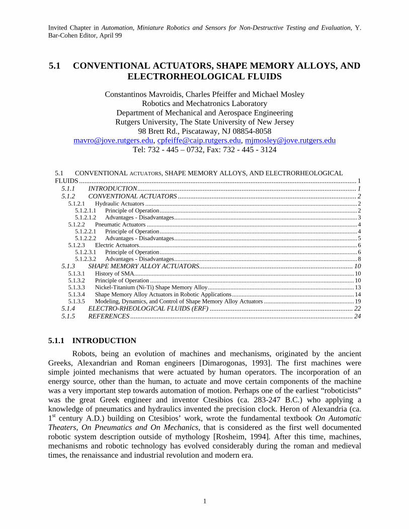
A representative closed loop position control for a linear hydraulic actuator is shown inFigure 2. The open loop dynamics of the hydraulic actuator are usually approximated with a firstorder system where the time constant depends on the piston area A. The desired piston positionXd is compared to the actual position X. The obtained error E is processed by the controllerwhich in most of the cases is a PID controller and the drive current I which will be the input tothe servo-valve is obtained. Then the current I is multiplied with the flow gain Kq and the servo-valve no-load flow Q0 is obtained. The Output Flow Q is the difference between Q0 and a flowQd due to disturbance forces Fd which are mainly friction and gravity. Flow Q is the input to thehydraulic system that will result in a piston velocity V and a piston displacement X.
Figure 2: Closed Loop Position Control of a Hydraulic Actuator
It has to be noted that in Figure 2, the dynamics of the servo-valve have beenapproximated with very simple linear relationships. This representation can be realistic in lowfrequency operations. However, in high frequencies, electro-hydraulic servo-valves can exhibithighly non-linear dynamics. [Hollerbach, Hunter and Ballantyne, 1992].
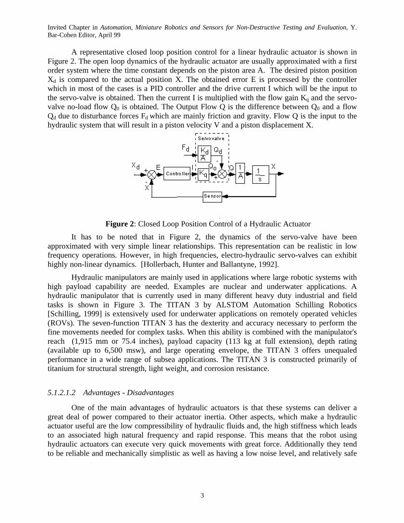
Hydraulic manipulators are mainly used in applications where large robotic systems withhigh payload capability are needed. Examples are nuclear and underwater applications. Ahydraulic manipulator that is currently used in many different heavy duty industrial and fieldtasks is shown in Figure 3. The TITAN 3 by ALSTOM Automation Schilling Robotics[Schilling, 1999] is extensively used for underwater applications on remotely operated vehicles(ROVs). The seven-function TITAN 3 has the dexterity and accuracy necessary to perform thefine movements needed for complex tasks. When this ability is combined with the manipulator'sreach (1,915 mm or 75.4 inches), payload capacity (113 kg at full extension), depth rating(available up to 6,500 msw), and large operating envelope, the TITAN 3 offers unequaledperformance in a wide range of subsea applications. The TITAN 3 is constructed primarily oftitanium for structural strength, light weight, and corrosion resistance.
5.1.2.1.2 Advantages - Disadvantages
One of the main advantages of hydraulic actuators is that these systems can deliver agreat deal of power compared to their actuator inertia. Other aspects, which make a hydraulicactuator useful are the low compressibility of hydraulic fluids and, the high stiffness which leadsto an associated high natural frequency and rapid response. This means that the robot usinghydraulic actuators can execute very quick movements with great force. Additionally they tendto be reliable and mechanically simplistic as well as having a low noise level, and relatively safe
Invited Chapter in Automation, Miniature Robotics and Sensors for Non-Destructive Testing and Evaluation, Y.Bar-Cohen Editor, April 99
4
during operation. As for this method of actuation, design characteristics are well known so theprocess of design is made easier due to this extent of knowledge.
Figure 3: Schilling TITAN 3 Manipulator [Schilling, 1999][Reprinted by permission of Schilling]
One of the larger concerns with hydraulic systems is the containment of the fluid withinthe actuation system. Not only is this because of the contamination of the surroundingenvironment, but the leakage can also contaminate the oil and possibly lead to damage of interiorsurfaces. Additionally, the hydraulic fluid is flammable and pressurized so leaks could pose anextreme hazard to equipment and personnel. This adds the undesirable aspect of additionalmaintenance to maintain a clean sealed system. Other drawbacks include lags in the control ofthe system due to the transmission lines and oil viscosity changes from temperature. In fact, suchtemperature changes in the fluid can be drastic enough to form vapor bubbles when combinedwith the changes in fluid pressure in a phenomena called cavitation. During operation astemperature and pressure fluctuate, these bubbles alternately form and collapse. At times, when avapor bubble is collapsing, the fluid will strike interior surfaces which had vapor filled pores andhigh surge pressures will be exhibited at the bottom of these pores. This bubble collapsing candislodge metal particles in the pore area and leave a metallic suspension within the fluid. Thedegradation of the interior surfaces and the contamination of the fluid result in a marked drop inthe performance of the system.
5.1.2.2 Pneumatic Actuators
5.1.2.2.1 Principle of Operation
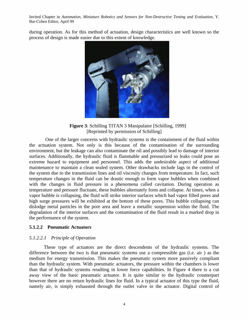
These type of actuators are the direct descendents of the hydraulic systems. Thedifference between the two is that pneumatic systems use a compressible gas (i.e. air ) as themedium for energy transmission. This makes the pneumatic system more passively compliantthan the hydraulic system. With pneumatic actuators, the pressure within the chambers is lowerthan that of hydraulic systems resulting in lower force capabilities. In Figure 4 there is a cutaway view of the basic pneumatic actuator. It is quite similar to the hydraulic counterparthowever there are no return hydraulic lines for fluid. In a typical actuator of this type the fluid,namely air, is simply exhausted through the outlet valve in the actuator. Digital control of
Invited Chapter in Automation, Miniature Robotics and Sensors for Non-Destructive Testing and Evaluation, Y.Bar-Cohen Editor, April 99
5
pneumatic systems is very similar to hydraulics with some exceptions to gains and stiffnessconstants (see also Figure 2.)
. Figure 4: Cutaway View of Pneumatic Actuator
[Stewart, 1987, pg. 316; Reprinted by permission of Macmillan Publishing]
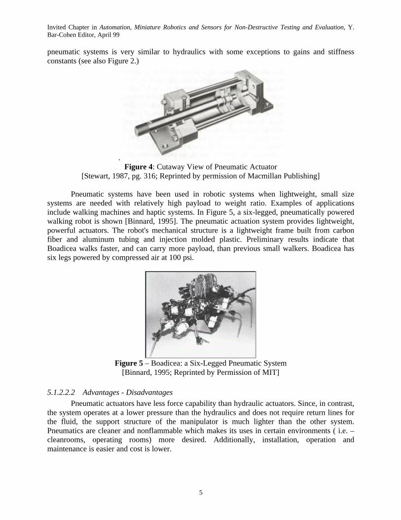
Pneumatic systems have been used in robotic systems when lightweight, small sizesystems are needed with relatively high payload to weight ratio. Examples of applicationsinclude walking machines and haptic systems. In Figure 5, a six-legged, pneumatically poweredwalking robot is shown [Binnard, 1995]. The pneumatic actuation system provides lightweight,powerful actuators. The robot's mechanical structure is a lightweight frame built from carbonfiber and aluminum tubing and injection molded plastic. Preliminary results indicate thatBoadicea walks faster, and can carry more payload, than previous small walkers. Boadicea hassix legs powered by compressed air at 100 psi.
Figure 5 – Boadicea: a Six-Legged Pneumatic System[Binnard, 1995; Reprinted by Permission of MIT]
5.1.2.2.2 Advantages - Disadvantages
Pneumatic actuators have less force capability than hydraulic actuators. Since, in contrast,the system operates at a lower pressure than the hydraulics and does not require return lines forthe fluid, the support structure of the manipulator is much lighter than the other system.Pneumatics are cleaner and nonflammable which makes its uses in certain environments ( i.e. –cleanrooms, operating rooms) more desired. Additionally, installation, operation andmaintenance is easier and cost is lower.
Invited Chapter in Automation, Miniature Robotics and Sensors for Non-Destructive Testing and Evaluation, Y.Bar-Cohen Editor, April 99
6
Though the lack of hydraulic fluid makes this system cleaner, it has the disadvantage ofnot having a self-lubricating actuator. This generally means that pneumatic systems have a highfriction force to overcome in order to maneuver and the diversion of power to combat frictiongives these systems a lower working force. The release valve that allows pressurized air toescape has a tendency to be load if a muffler is not employed. Of course due to the mediumwhich is compressible, control of motion is handled differently than hydraulics. Whilecompliance is desired in a hydraulic system, force and speed are wanting in a pneumatic setuptherefore the methodology to get these performance aspects is left to ingenuity of softwarecontrol and nozzle design.
5.1.2.3 Electric Actuators
5.1.2.3.1 Principle of Operation
Of the three types of conventional actuator systems, electric motors have the largestvariety of possible devices such as: Direct Current (DC) motors and their variants (brushed andbrushless, low inertia, geared and direct drive, permanent magnet), Alternate Current (AC)motors, Induction Motors, and Stepping Motors. By definition, the principle behind an electricmotor is a simple one, which is the application of magnetic fields to a ferrous core and therebyinducing motion.
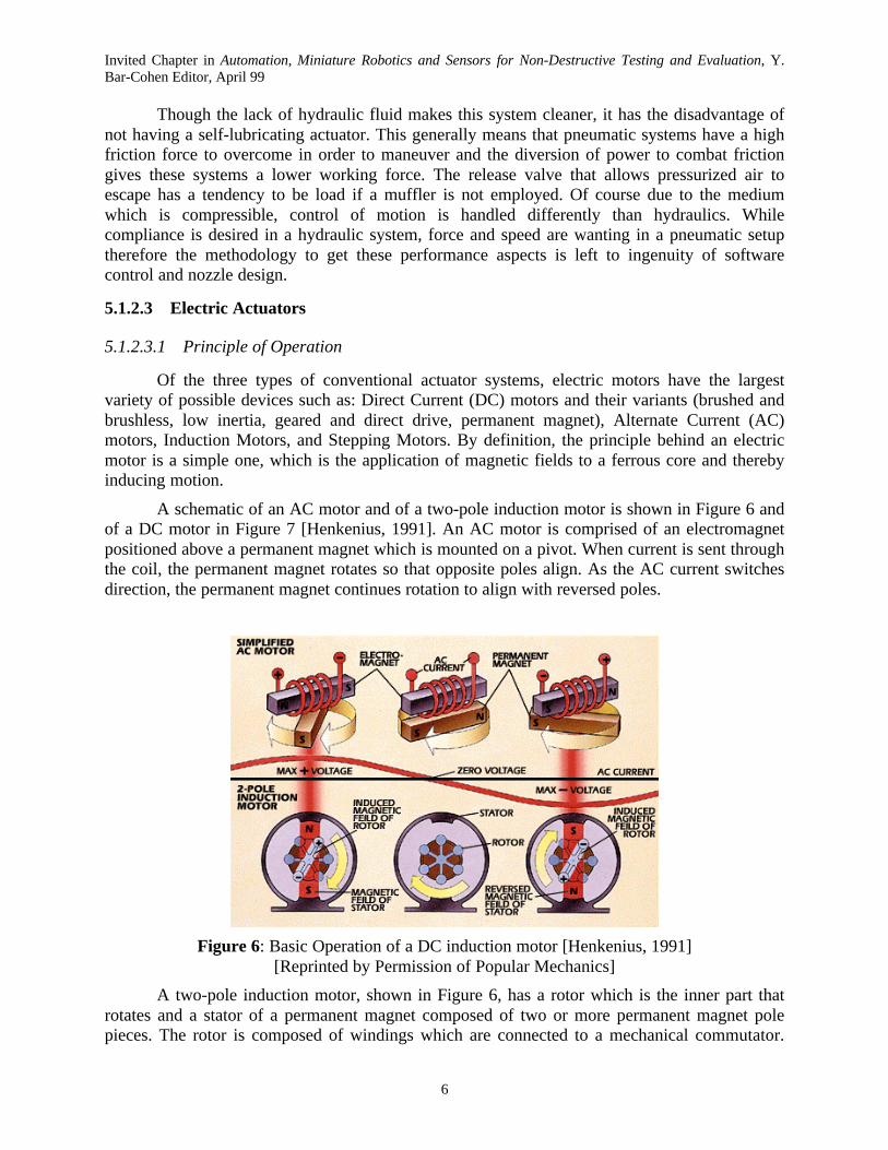
A schematic of an AC motor and of a two-pole induction motor is shown in Figure 6 andof a DC motor in Figure 7 [Henkenius, 1991]. An AC motor is comprised of an electromagnetpositioned above a permanent magnet which is mounted on a pivot. When current is sent throughthe coil, the permanent magnet rotates so that opposite poles align. As the AC current switchesdirection, the permanent magnet continues rotation to align with reversed poles.
Figure 6: Basic Operation of a DC induction motor [Henkenius, 1991][Reprinted by Permission of Popular Mechanics]
A two-pole induction motor, shown in Figure 6, has a rotor which is the inner part thatrotates and a stator of a permanent magnet composed of two or more permanent magnet polepieces. The rotor is composed of windings which are connected to a mechanical commutator.

Invited Chapter in Automation, Miniature Robotics and Sensors for Non-Destructive Testing and Evaluation, Y.Bar-Cohen Editor, April 99
7
The opposite polarities of the energized winding and the stator magnet attract and the rotor willrotate until it is aligned with the stator. Just as the rotor reaches alignment, the brushes moveacross the commutator contacts and energize the next winding. Notice that the commutator isstaggered from the rotor poles. If the connections of a motor are reversed, the motor will changedirections. DC motors are very similar to induction motors. The only difference is that a currentis sent to the armature through contact between brushes and commutator. Spinning commutatoracts as a reversing switch that alternates magnetic field.
Figure 7: Block diagram of a DC motor [Henkenius, 1991][Reprinted by Permission of Popular Mechanics]
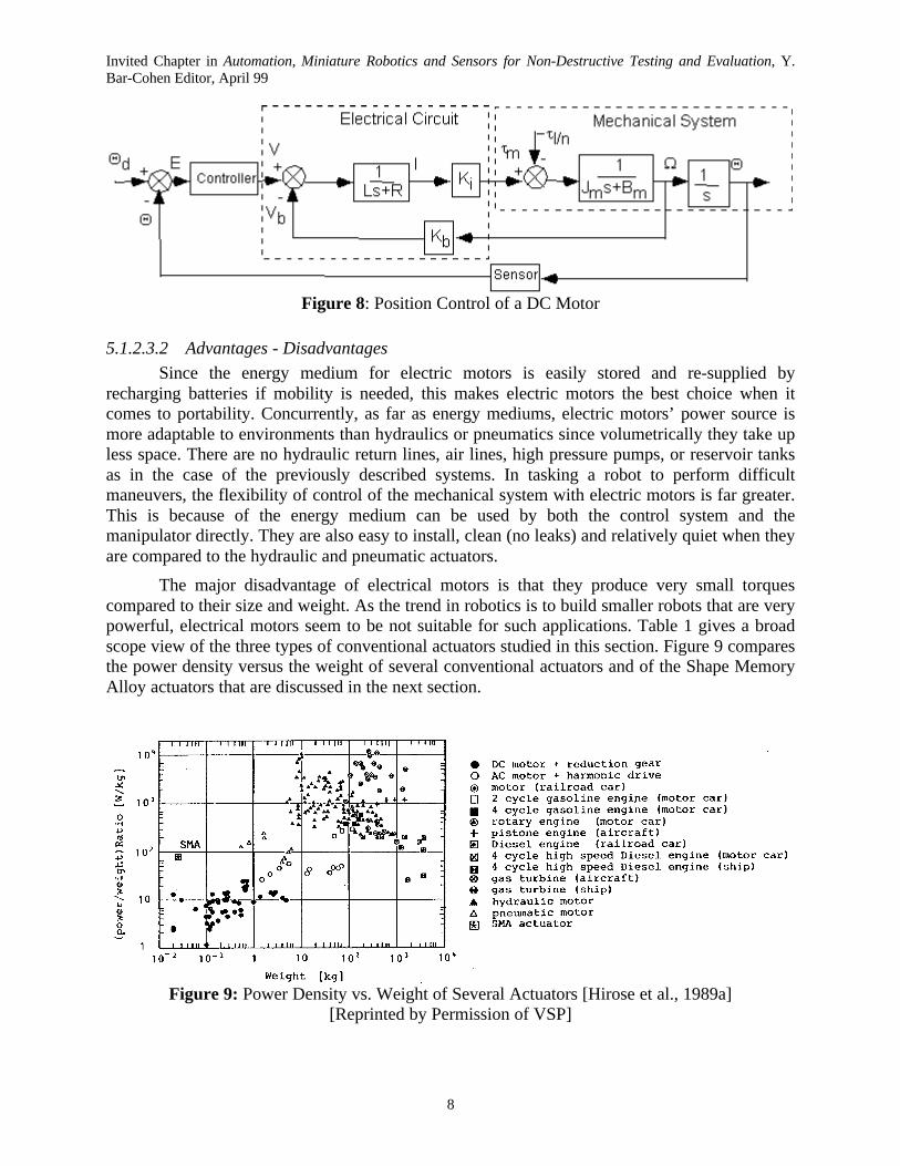
A position control scheme, in the Laplace domaine, for a permanent magnet DC motor isshown in Figure 8. The desired motor position Θd (and velocity) is compared to the actualposition Θ (and velocity) that is usually obtained using angular position sensor such as opticalencoders or potensiometers. This comparison yield the position (and velocity) error E that isprocessed by the controller. Usually, a PID controller is used and is designed to achieve fast andaccurate response with no overshoot. The output of the controller is the voltage V that will be theinput to the DC motor. Voltage V will be reduced by the "back emf" voltage Vb which is createdby the angular motion of the motor shaft. The back emf voltage is proportional to the angularvelocity Ω and the coefficient of this linear relationship is called the "back emf constant" Kb. Theopen loop dynamics of the motor are distinguished into the dynamics of the electrical part and ofthe mechanical part. The electrical circuit dynamics are approximated using a first order systemwhere L is the armature inductance and R is the armature resistance. The armature current Iwhich is the output of the electrical part, will result in the motor torque τm. The relationshipbetween I and τm is linear and the coefficient Ki of this linear relationship is called the "motorconstant". The sum of the motor torque τm with the disturbance torques τl felt by the motor shaftwill be the input to the mechanical part of a DC motor. The disturbance torques τl are due to theload carried by the motor, friction and elastic effects at the payload level and other dynamiceffects that have not been taken into account by the model. The coefficient n is the gear ratio anddivides any torques due to the payload. The dynamics of the mechanical part are of second order,including a motor inertia Jm and a friction term with friction coefficient Bm. A detaileddescription of the control of a DC motor can be found in [Spong and Vidyasagar, 1989].
Invited Chapter in Automation, Miniature Robotics and Sensors for Non-Destructive Testing and Evaluation, Y.Bar-Cohen Editor, April 99
8
Figure 8: Position Control of a DC Motor
5.1.2.3.2 Advantages - Disadvantages
Since the energy medium for electric motors is easily stored and re-supplied byrecharging batteries if mobility is needed, this makes electric motors the best choice when itcomes to portability. Concurrently, as far as energy mediums, electric motors’ power source ismore adaptable to environments than hydraulics or pneumatics since volumetrically they take upless space. There are no hydraulic return lines, air lines, high pressure pumps, or reservoir tanksas in the case of the previously described systems. In tasking a robot to perform difficultmaneuvers, the flexibility of control of the mechanical system with electric motors is far greater.This is because of the energy medium can be used by both the control system and themanipulator directly. They are also easy to install, clean (no leaks) and relatively quiet when theyare compared to the hydraulic and pneumatic actuators.
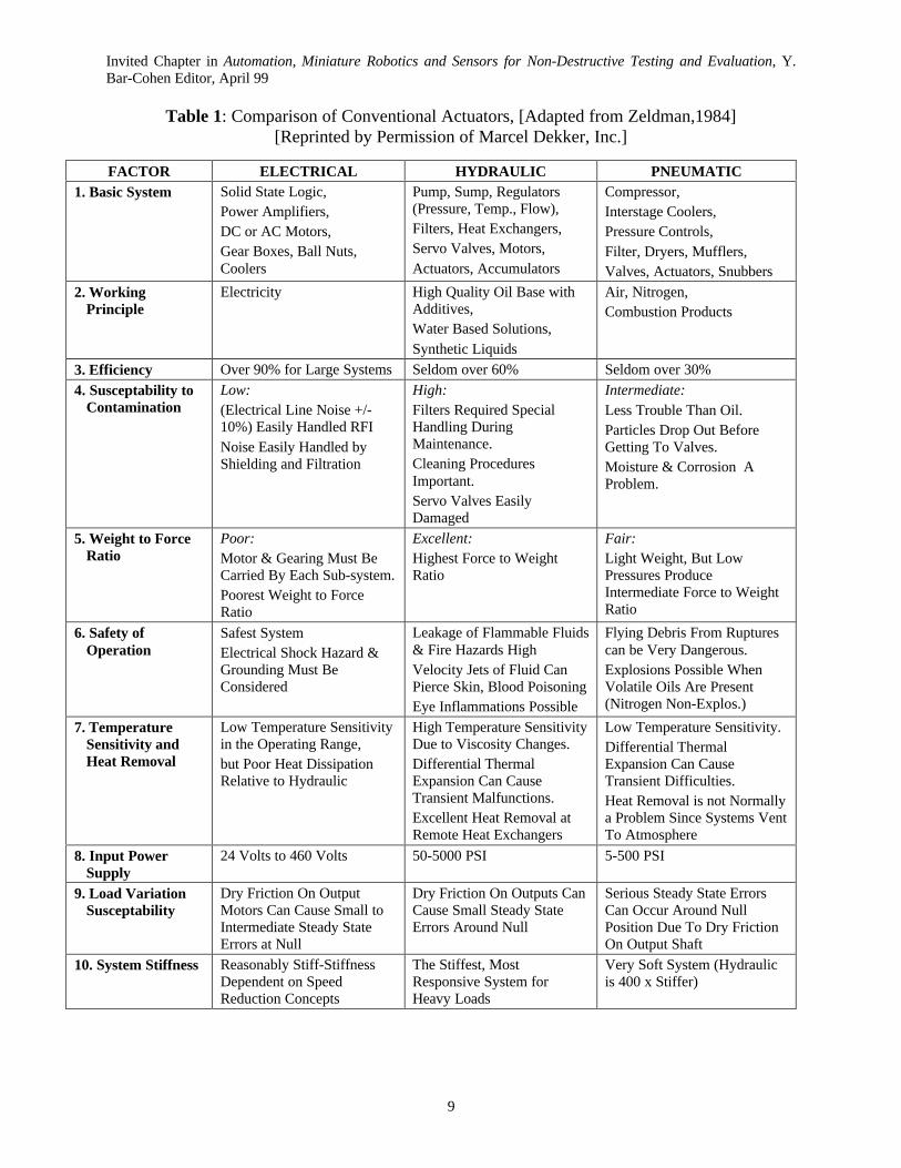
The major disadvantage of electrical motors is that they produce very small torquescompared to their size and weight. As the trend in robotics is to build smaller robots that are verypowerful, electrical motors seem to be not suitable for such applications. Table 1 gives a broadscope view of the three types of conventional actuators studied in this section. Figure 9 comparesthe power density versus the weight of several conventional actuators and of the Shape MemoryAlloy actuators that are discussed in the next section.
Figure 9: Power Density vs. Weight of Several Actuators [Hirose et al., 1989a][Reprinted by Permission of VSP]
Invited Chapter in Automation, Miniature Robotics and Sensors for Non-Destructive Testing and Evaluation, Y.Bar-Cohen Editor, April 99
9
Table 1: Comparison of Conventional Actuators, [Adapted from Zeldman,1984][Reprinted by Permission of Marcel Dekker, Inc.]
FACTOR ELECTRICAL HYDRAULIC PNEUMATIC1. Basic System Solid State Logic,
Power Amplifiers,DC or AC Motors,Gear Boxes, Ball Nuts,Coolers
Pump, Sump, Regulators(Pressure, Temp., Flow),Filters, Heat Exchangers,Servo Valves, Motors,Actuators, Accumulators
Compressor,Interstage Coolers,Pressure Controls,Filter, Dryers, Mufflers,Valves, Actuators, Snubbers
2. WorkingPrinciple
Electricity High Quality Oil Base withAdditives,Water Based Solutions,Synthetic Liquids
Air, Nitrogen,Combustion Products
3. Efficiency Over 90% for Large Systems Seldom over 60% Seldom over 30%
4. Susceptability toContamination
Low:(Electrical Line Noise +/-10%) Easily Handled RFINoise Easily Handled byShielding and Filtration
High:Filters Required SpecialHandling DuringMaintenance.Cleaning ProceduresImportant.Servo Valves EasilyDamaged
Intermediate:Less Trouble Than Oil.Particles Drop Out BeforeGetting To Valves.Moisture & Corrosion AProblem.
5. Weight to ForceRatio
Poor:Motor & Gearing Must BeCarried By Each Sub-system.Poorest Weight to ForceRatio
Excellent:Highest Force to WeightRatio
Fair:Light Weight, But LowPressures ProduceIntermediate Force to WeightRatio
6. Safety ofOperation
Safest SystemElectrical Shock Hazard &Grounding Must BeConsidered
Leakage of Flammable Fluids& Fire Hazards HighVelocity Jets of Fluid CanPierce Skin, Blood PoisoningEye Inflammations Possible
Flying Debris From Rupturescan be Very Dangerous.Explosions Possible WhenVolatile Oils Are Present(Nitrogen Non-Explos.)
7. TemperatureSensitivity andHeat Removal
Low Temperature Sensitivityin the Operating Range,but Poor Heat DissipationRelative to Hydraulic
High Temperature SensitivityDue to Viscosity Changes.Differential ThermalExpansion Can CauseTransient Malfunctions.Excellent Heat Removal atRemote Heat Exchangers
Low Temperature Sensitivity.Differential ThermalExpansion Can CauseTransient Difficulties.Heat Removal is not Normallya Problem Since Systems VentTo Atmosphere
8. Input PowerSupply
24 Volts to 460 Volts 50-5000 PSI 5-500 PSI
9. Load VariationSusceptability
Dry Friction On OutputMotors Can Cause Small toIntermediate Steady StateErrors at Null
Dry Friction On Outputs CanCause Small Steady StateErrors Around Null
Serious Steady State ErrorsCan Occur Around NullPosition Due To Dry FrictionOn Output Shaft
10. System Stiffness Reasonably Stiff-StiffnessDependent on SpeedReduction Concepts
The Stiffest, MostResponsive System forHeavy Loads
Very Soft System (Hydraulicis 400 x Stiffer)

Invited Chapter in Automation, Miniature Robotics and Sensors for Non-Destructive Testing and Evaluation, Y.Bar-Cohen Editor, April 99
10
5.1.3 SHAPE MEMORY ALLOY ACTUATORS
5.1.3.1 History of SMA
In 1932, a Swedish physicist by the name of Arne Olander discovered an interestingphenomenon when working with an alloy of gold (Au) and cadmium (Cd). The Au-Cd alloycould be plastically deformed when cool and then be heated to return to, or “remember”, theoriginal dimensional configuration. This phenomenon is known as the Shape Memory Effect(SME) and the alloys that exhibit the behavior are called Shape Memory Alloys (SMA). In1958, researchers Chang and Read demonstrated the Shape Memory Effect at the BrusselsWorld’s Fair. Specifically, they showed that the SME could be used to perform mechanicalwork by cyclically lifting a weight using a Au-Cd SMA. Further research revealed othermaterials that demonstrate this phenomenon. In 1961, a group of U. S. Naval OrdnanceLaboratory researchers lead by William Beuhler stumbled across a significant discovery in thefield of SME and SMA. While testing an alloy of Nickel and Titanium for heat and corrosionresistance, they found that it too exhibited the SME. The Ni-Ti SMA proved to be significantlyless expensive, easier to work with, and less dangerous (from health standpoint) than previouslydiscovered alloys. These factors refreshed interest and research in the Shape Memory Effect andits applications. [Toki Corporation, 1987; Grant, 1995]
Researchers, designers, and companies recognized the potential to use the SME inengineering applications. As a result, starting in the 1970’s, commercial products began toappear. For the most part, the early devices functioned as fasteners and took advantage of asingle shape memory dimensional change. Some examples of these static devices are couplingsfor piping systems and electrical connectors. Next, researchers began to propose SMA devicesto perform dynamic tasks; thus, they began to play the role of actuators. In order to perform adynamic task, the SMA must experience a cycle of heating, cooling, and deformation. Thisrequirement led some companies, such as Delta Metal in England, to use SMA actuators intemperature regulation systems where the environmental temperature could be used for thermalactuation. Delta Metal proposed that SMA devices could be used to automatically open andclose greenhouse windows, operate valves that control building temperatures, and controlautomobile fan clutches. In 1982, Sharp incorporated SMA actuators into electric oven dampersand in 1983, Matsushita Electric designed SMA actuated louvers for air conditioners [TokiCorporation, 1987]. Other researchers pursued electricity (resisitive or joule heating) as a sourceof heat and thus actuation. In 1971, a team lead by Sawyer developed and tested an artificialheart powered by electrical actuation of SMA elements. In 1983, Honma, Miwa, and Iguchi[Honma et al, 1989] showed that SMA actuation could be controlled by resistive heating andproposed that SMA actuators could be used in micro-robotics. Research concerning theapplication and control of SMA actuators in robotic systems has continued and expandedthrough the present.
5.1.3.2 Principle of Operation
Shape Memory Alloys consist of a group of metallic materials that demonstrate theability to return to some previously defined shape or size when subjected to the appropriatethermal procedure. Some examples of these alloys are Ag-Cd, Au-Cd, Cu-Al-Ni, Cu-Sn, Cu-Zn-(X), In-Ti, Ni-Al, Ni-Ti, Fe-Pt, Mn-Cu, and Fe-Mn-Si. The SME occurs due to a temperature

Invited Chapter in Automation, Miniature Robotics and Sensors for Non-Destructive Testing and Evaluation, Y.Bar-Cohen Editor, April 99
11
and stress dependent shift in the material’s crystalline structure between two different phasescalled martensite and austenite. Martensite, the low temperature phase, is relatively soft whereasAustenite, the high temperature phase, is relatively hard. For a simple example of the SME inaction, consider the following. If a straight bar of some SMA in its austenitic (high temperature)phase is allowed to cool below the phase transition temperature, the crystalline structure willchange to martensite. If the bar is subsequently plastically deformed, by say bending, and thenreheated above the phase transition temperature, it will return to its original straightconfiguration. In order to understand this phenomenon, it is useful to consider the highlysimplified two-dimensional representation of the material’s crystalline arrangement shown inFigure 10.
Figure 10: Material Crystalline Arrangement During the Shape Memory Effect
Each box represents a grain of material with its corresponding grain boundaries. Thegrains form a heavily twinned structure, meaning they are oriented symmetrically across grainboundaries. The twinned structure allows the internal lattice of individual grains to change whilestill maintaining the same interface with adjacent grains. As a result, Shape Memory Alloys canexperience large macroscopic deformations while maintaining remarkable order within itsmicroscopic structure. For example, if a piece of SMA starts as austenite (Figure 10a), theinternal atomic lattice of each grain is cubic creating grains with more or less right angles. If it isnow allowed to cool below the phase transition temperature, the crystalline structure changes tomartensite (Figure 10b) and the grains collapse to the structure represented by the diamonds.Note that the grains lean in different directions for different layers. Now, if sufficient stress isapplied, the martensitic structure represented in Figure 10b will start to yield and “de-twin” asthe grains re-orient such that they are all aligned in the same direction (see Figure 10c). Thisbehavior can be better understood by examining a typical stress-strain curve for the martensitephase (Figure 11). For small stresses, the structure represented in Figure 10b behaves elastically(region 0 to 1). At 1, the material yields and de-twinning occurs between 1 and 2. At 2, themartensitic structure is entirely de-twinned as represented by Figure 10c. Now, a second elastic
Invited Chapter in Automation, Miniature Robotics and Sensors for Non-Destructive Testing and Evaluation, Y.Bar-Cohen Editor, April 99
12
region occurs from 2 to 3. At 3, permanent plastic deformation begins that is not recoverable bythe SME.
Figure 11: Stress -Strain Relationship of a Shape Memory Alloy
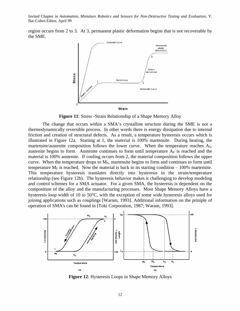
The change that occurs within a SMA’s crystalline structure during the SME is not athermodynamically reversible process. In other words there is energy dissipation due to internalfriction and creation of structural defects. As a result, a temperature hysteresis occurs which isillustrated in Figure 12a. Starting at 1, the material is 100% martensite. During heating, themartensite/austenite composition follows the lower curve. When the temperature reaches AS,austenite begins to form. Austenite continues to form until temperature AF is reached and thematerial is 100% austenite. If cooling occurs from 2, the material composition follows the uppercurve. When the temperature drops to MS, martensite begins to form and continues to form untiltemperature MF is reached. Now the material is back to its starting condition – 100% martensite.This temperature hysteresis translates directly into hysteresis in the strain/temperaturerelationship (see Figure 12b). The hysteresis behavior makes it challenging to develop modelingand control schemes for a SMA actuator. For a given SMA, the hysteresis is dependent on thecomposition of the alloy and the manufacturing processes. Most Shape Memory Alloys have ahysteresis loop width of 10 to 50°C, with the exception of some wide hysteresis alloys used forjoining applications such as couplings [Waram, 1993]. Additional information on the priniple ofoperation of SMA's can be found in [Toki Corporation, 1987; Waram, 1993].
Figure 12: Hysteresis Loops in Shape Memory Alloys
Invited Chapter in Automation, Miniature Robotics and Sensors for Non-Destructive Testing and Evaluation, Y.Bar-Cohen Editor, April 99
13
5.1.3.3 Nickel-Titanium (Ni-Ti) Shape Memory Alloy
Out of all the Shape Memory Alloys that have been discovered so far, Nickel-Titanium(Ni-Ti) has proven to be the most flexible and beneficial in engineering applications. Thefollowing characteristics of Ni-Ti make it stand out from the other SMA’s: greater ductility,more recoverable motion, excellent corrosion resistance (comparable to series 300 stainlesssteels), stable transformation temperatures, high biocompatability, and the ability to beelectrically heated for shape recovery [Waram, 1993].
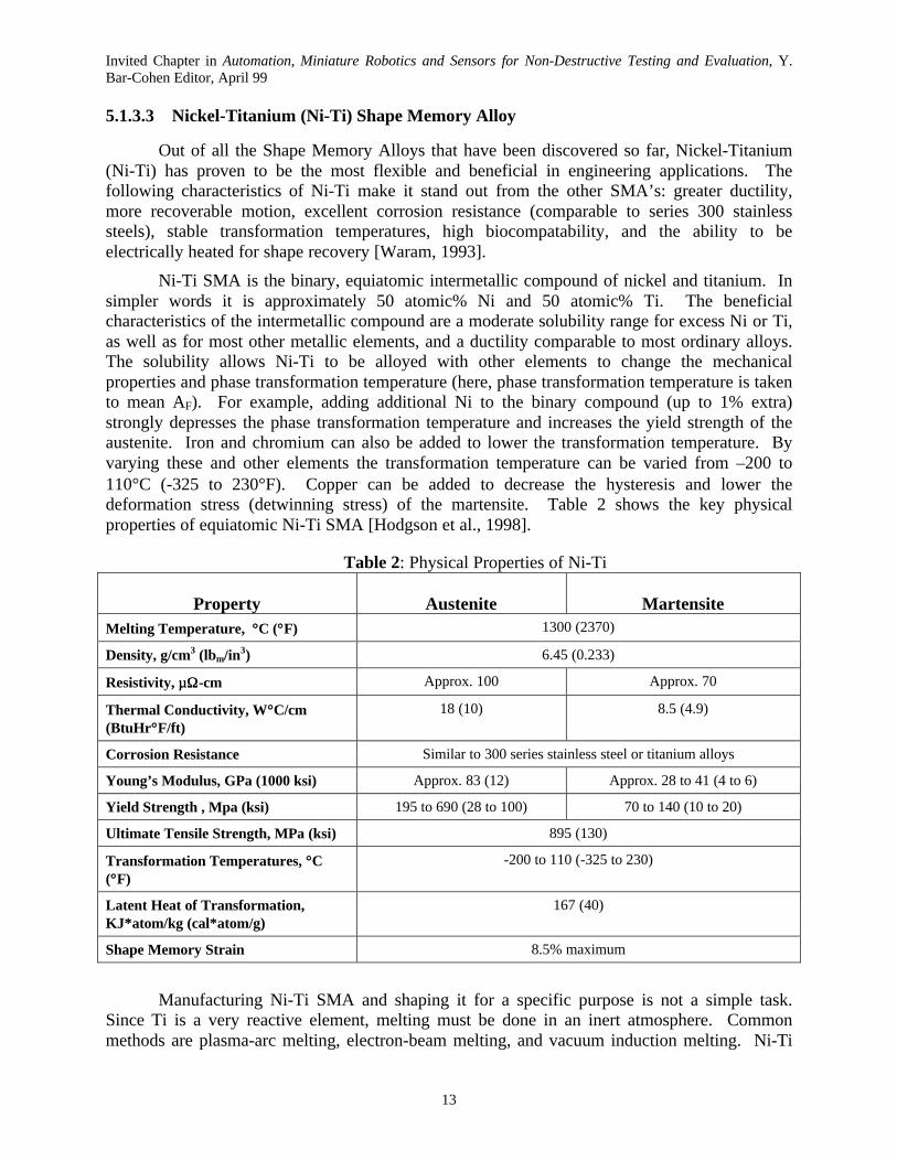
Ni-Ti SMA is the binary, equiatomic intermetallic compound of nickel and titanium. Insimpler words it is approximately 50 atomic% Ni and 50 atomic% Ti. The beneficialcharacteristics of the intermetallic compound are a moderate solubility range for excess Ni or Ti,as well as for most other metallic elements, and a ductility comparable to most ordinary alloys.The solubility allows Ni-Ti to be alloyed with other elements to change the mechanicalproperties and phase transformation temperature (here, phase transformation temperature is takento mean AF). For example, adding additional Ni to the binary compound (up to 1% extra)strongly depresses the phase transformation temperature and increases the yield strength of theaustenite. Iron and chromium can also be added to lower the transformation temperature. Byvarying these and other elements the transformation temperature can be varied from –200 to110°C (-325 to 230°F). Copper can be added to decrease the hysteresis and lower thedeformation stress (detwinning stress) of the martensite. Table 2 shows the key physicalproperties of equiatomic Ni-Ti SMA [Hodgson et al., 1998].
Table 2: Physical Properties of Ni-Ti
Property Austenite MartensiteMelting Temperature, °°C (°°F) 1300 (2370)
Density, g/cm3 (lbm/in3) 6.45 (0.233)
Resistivity, µµΩΩ-cm Approx. 100 Approx. 70
Thermal Conductivity, W°°C/cm(BtuHr°°F/ft)
18 (10) 8.5 (4.9)
Corrosion Resistance Similar to 300 series stainless steel or titanium alloys
Young’s Modulus, GPa (1000 ksi) Approx. 83 (12) Approx. 28 to 41 (4 to 6)
Yield Strength , Mpa (ksi) 195 to 690 (28 to 100) 70 to 140 (10 to 20)
Ultimate Tensile Strength, MPa (ksi) 895 (130)
Transformation Temperatures, °°C(°°F)
-200 to 110 (-325 to 230)
Latent Heat of Transformation,KJ∗∗atom/kg (cal∗∗atom/g)
167 (40)
Shape Memory Strain 8.5% maximum
Manufacturing Ni-Ti SMA and shaping it for a specific purpose is not a simple task.Since Ti is a very reactive element, melting must be done in an inert atmosphere. Commonmethods are plasma-arc melting, electron-beam melting, and vacuum induction melting. Ni-Ti
Invited Chapter in Automation, Miniature Robotics and Sensors for Non-Destructive Testing and Evaluation, Y.Bar-Cohen Editor, April 99
14
ingots can be initially shaped using standard hot-forming and cold-working processes. Duringcold-working the alloy work hardens very quickly and must be annealed frequently. Workhardening and the correct heat treatment can be used to improve the SMA’s performance byreducing the stress needed to de-twin the martensite and increasing the strength in the austenitephase. Machining Ni-Ti through cutting methods is difficult, as is welding, brazing, andsoldering. Grinding, shearing, and punching are often better methods to create specific shapes.The “memory configuration” of a SMA part is defined by restraining the part in the desiredshape, and then heat treating at typically 500 to 800°C (950 to 1450°F) [Hodgson et al., 1998].Companies such as Dynalloy, Inc. and Shape Memory Applications, Inc. provide prefabricatedSMA elements such as wire, rod, ribbon, strip, sheet, and tubing. Additionally, they are able tocreate custom elements to user specifications.
5.1.3.4 Shape Memory Alloy Actuators in Robotic Applications
Using Shape Memory Alloy actuators provides an interesting alternative to conventionalactuation methods. Their advantages create a means to drastically reduce the size, weight, andcomplexity of robotic systems. First of all, SMA actuators possess an extremely high force toweight ratio. A Ni-Ti actuator can apply an actuation stress of 500 MPa ( 72.5 ksi). So, a 150µm diameter Ni-Ti wire can apply a force of 8.8 N which is 0.897 kgf (1.99 lbf). If the wire is 10cm (3.94 in.) long it would weigh 11.4 mg (0.025 lbm) and could contract 0.85 cm. So, theactuator can lift an object 78,000 times its own weight nearly 1 cm! Granted a simple electricalcircuit is needed to heat the wire, but the force to weight ratio is still remarkable. Shape MemoryAlloy actuators also are incredibly compact and simple. In the example described above, theactuator itself has a volume of only 0.002 cm2. A SMA actuation system consists only of theSMA element and a heating and cooling method. The cooling method can be as simple as acombination of natural convection, conduction, and radiation. A final advantage is noiselessoperation. Whereas conventional actuators produce a significant amount of noise, the SMAactuator is completely silent.
Shape Memory Alloy actuators do have disadvantages which must be thoroughlyconsidered and analyzed prior to deciding to use SMA for an application. First of all, theyoperate with a low efficiency. A SMA actuator is effectively a heat engine where the materialconverts thermal energy directly into work. Therefore, the efficiency of the actuator cannot begreater than that of the Carnot cycle. The efficiency of the Carnot cycle is low in thetemperatures where typical SMA actuator operate -- not exceeding 10% [Hirose, Ikuta, andUmetani, 1984]. Second, SMA actuators operate at a low bandwidth, meaning they are relativeslow to cycle. The cycling time is primarily dependent on the heat transfer characteristics of theSMA “cooling system”. The primary parameters that affect bandwidth are the temperature andtype of surrounding medium, the convection of the surrounding medium, and the surface tovolume ratio of the SMA elements. Depending on the environment, heat dissipation can be aproblem. For a high temperature, low convection environment, the heat transfer to thesurrounding medium is reduced resulting in a lower bandwidth. For a low temperature or highconvection environment, the heat transfer is improved and bandwidth is increased. However,greater heat transfer also means that more power is needed to achieve actuation temperature.Another disadvantage of SMA actuators is the small absolute strains achieved by the SMAmaterial. With only 8.5% strain available (for Ni=Ti), mechanisms actuated by SMA that arerequired to create large motions must be cleverly designed. Converting small motions into largemotions comes with the unavoidable reduction in mechanical advantage. A final disadvantage,
Invited Chapter in Automation, Miniature Robotics and Sensors for Non-Destructive Testing and Evaluation, Y.Bar-Cohen Editor, April 99
15
and topic of much research, is the difficulty controlling SMA actuators. The Shape MemoryEffect is a highly non-linear phenomenon. Non-linearities enter the process through thehysteresis behavior described earlier, non-linear heat transfer, and any non-linear change in theparameters that affects the phase composition of the material (temperature, stress). Anothercontrol issue is that the entire deflection of a SMA element occurs over a small temperaturerange making accurate control in partial contraction difficult. Control is also difficult due to thestructural elasticity of SMA actuators.
When designing a Shape Memory Alloy actuator for a mechanism, one of the firstdecisions is specifying the source of heat to actuate the SMA element. In certain specializedapplications, the temperature of the surrounding medium can be used as a source of heat. Thismethod provides a excellent option when designing mechanisms that regulate temperature. Forexample, a SMA element can be placed in a medium (say air) whose temperature needs to becontrolled. The SMA element can be manufactured such that its actuation temperaturecorresponds to some critical temperature of the medium. When the medium reaches the criticaltemperature, the SMA element would actuate and possibly open a valve supplying more cooling.Here, the SMA element acts as both the sensor and the actuator. No electronics are needed inthis incredibly simple system.
For other applications, the typical source of heat to achieve actuation temperature is jouleheating by electric current. The electrical source can be either DC or AC. If AC, it should be ata frequency significantly higher than the bandwidth of the SMA actuated system to avoiddisplacement fluctuations. The current I that flows through a SMA element with resistance R,due to a certain voltage drop V and the corresponding power P can be found from the followingwell-known relationships:
R
VI = (1)
IVP = or RIP 2= (2)
Integrating a plot of power versus time and then dividing by the total time provides theaverage power. The average power required to achieve actuation temperature can be supplied bya steady or time varying signal. An example of a time varying signal that has been usedextensively in electrical actuation is Pulse Width Modulation (PWM). The advantage of thismethod is more uniform heating of the SMA element. As expected, larger voltages/currentscause more rapid actuation.
Shape Memory Alloy material can be formed into almost any shaped actuatorimaginable. All that is needed is a heat treatment process to define the actuators dimensionalconfiguration in the austenite (actuated) phase. Some shapes that have been used are cantileverbeams, wires, springs, ribbon, strip, sheet, and tubing. Although a SMA actuator could bedesigned such that it applies a force in three dimensions (depending on which direction it wasdeformed from the memory configuration), the great majority of SMA actuators apply a onedirectional tensile force and cannot directly apply a compressive force. In order to apply acompressive force, the actuator dimensions would have to be large enough to ensure rigidity andprevent buckling. As discussed earlier, large dimensions would cause a major decrease in thesurface to volume ratio and, consequently, bandwidth. The end result is in order to have a SMAactuator with sufficient bandwidth, the SMA element must be thin, making it only capable of
Invited Chapter in Automation, Miniature Robotics and Sensors for Non-Destructive Testing and Evaluation, Y.Bar-Cohen Editor, April 99
16
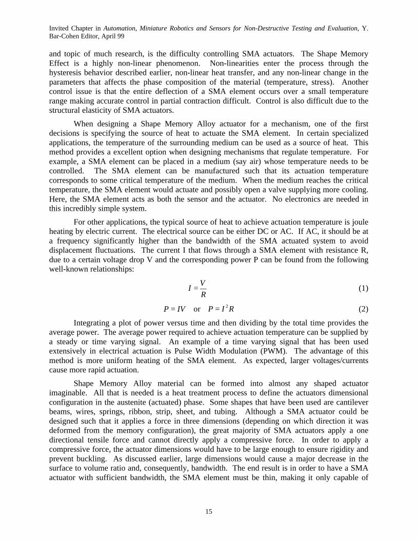
applying tensile forces. Since most mechanisms require cyclic motions, a bias force is needed toreturn the mechanism in the opposite direction from which it was pulled by the SMA actuator.This bias force can be supplied by stored potential energy (gravity or a spring) or be provided byanother SMA actuator working antagonistically. Simple examples of bias force are shown inFigure 13. Some excellent basic design principals for single element SMA Actuators can befound in [Waram, 1993].
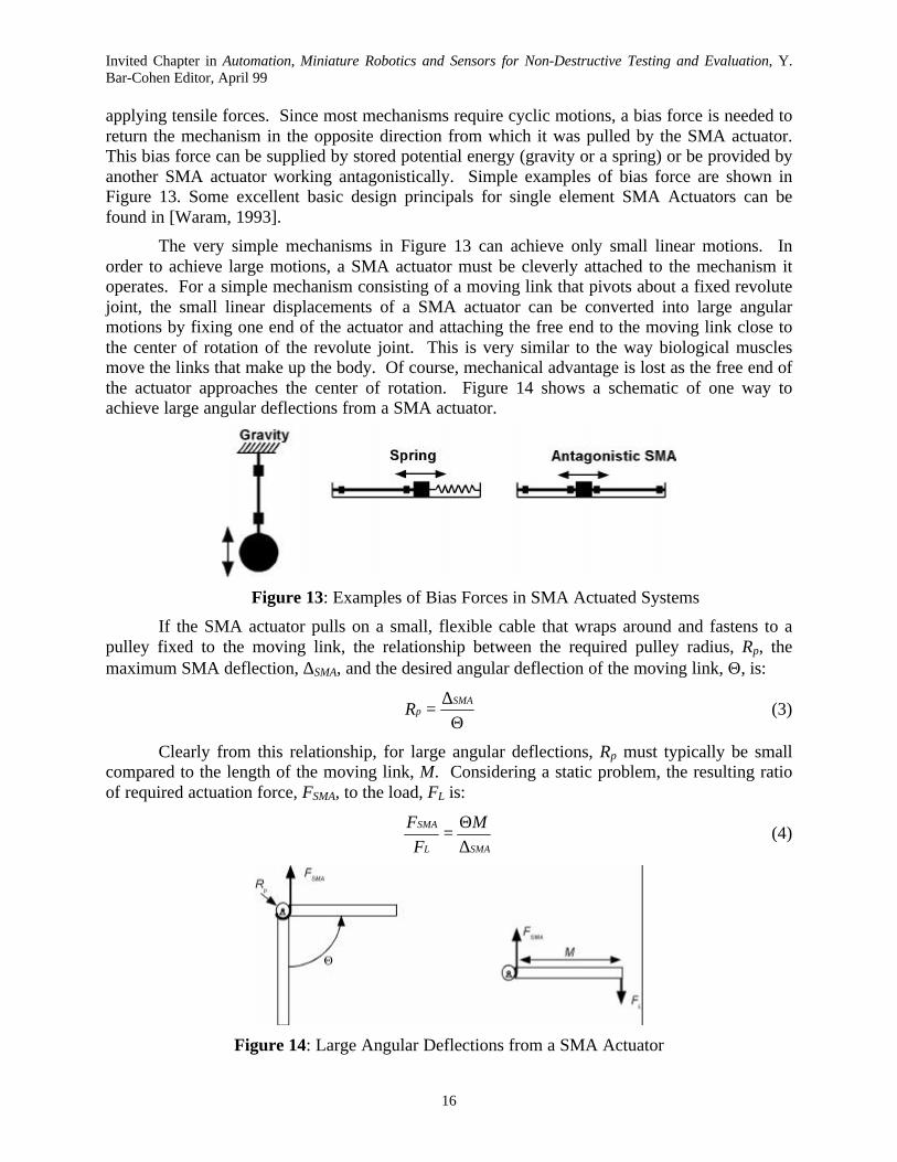
The very simple mechanisms in Figure 13 can achieve only small linear motions. Inorder to achieve large motions, a SMA actuator must be cleverly attached to the mechanism itoperates. For a simple mechanism consisting of a moving link that pivots about a fixed revolutejoint, the small linear displacements of a SMA actuator can be converted into large angularmotions by fixing one end of the actuator and attaching the free end to the moving link close tothe center of rotation of the revolute joint. This is very similar to the way biological musclesmove the links that make up the body. Of course, mechanical advantage is lost as the free end ofthe actuator approaches the center of rotation. Figure 14 shows a schematic of one way toachieve large angular deflections from a SMA actuator.
Figure 13: Examples of Bias Forces in SMA Actuated Systems
If the SMA actuator pulls on a small, flexible cable that wraps around and fastens to apulley fixed to the moving link, the relationship between the required pulley radius, Rp, themaximum SMA deflection, ∆SMA, and the desired angular deflection of the moving link, Θ, is:
Θ∆
=SMA
pR (3)
Clearly from this relationship, for large angular deflections, Rp must typically be smallcompared to the length of the moving link, M. Considering a static problem, the resulting ratioof required actuation force, FSMA, to the load, FL is:
SMAL
SMA M
F
F
∆Θ
= (4)
Figure 14: Large Angular Deflections from a SMA Actuator
Invited Chapter in Automation, Miniature Robotics and Sensors for Non-Destructive Testing and Evaluation, Y.Bar-Cohen Editor, April 99
17
Hirose et al., 1989b, sought to improve the torque performace of this basic mechanism byusing non-circular pulleys.
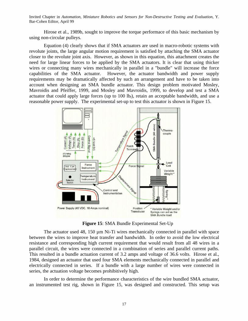
Equation (4) clearly shows that if SMA actuators are used in macro-robotic systems withrevolute joints, the large angular motion requirement is satisfied by attaching the SMA actuatorcloser to the revolute joint axis. However, as shown in this equation, this attachment creates theneed for large linear forces to be applied by the SMA actuators. It is clear that using thickerwires or connecting many wires mechanically in parallel in a "bundle" will increase the forcecapabilities of the SMA actuator. However, the actuator bandwidth and power supplyrequirements may be dramatically affected by such an arrangement and have to be taken intoaccount when designing an SMA bundle actuator. This design problem motivated Mosley,Mavroidis and Pfeiffer, 1999, and Mosley and Mavroidis, 1999, to develop and test a SMAactuator that could apply large forces (up to 100 lbf), retain an acceptable bandwidth, and use areasonable power supply. The experimental set-up to test this actuator is shown in Figure 15.
Figure 15: SMA Bundle Experimental Set-Up
The actuator used 48, 150 µm Ni-Ti wires mechanically connected in parallel with spacebetween the wires to improve heat transfer and bandwidth. In order to avoid the low electricalresistance and corresponding high current requirement that would result from all 48 wires in aparallel circuit, the wires were connected in a combination of series and parallel current paths.This resulted in a bundle actuation current of 3.2 amps and voltage of 36.6 volts. Hirose et al.,1984, designed an actuator that used four SMA elements mechanically connected in parallel andelectrically connected in series. If a bundle with a large number of wires were connected inseries, the actuation voltage becomes prohibitively high.
In order to determine the performance characteristics of the wire bundled SMA actuator,an instrumented test rig, shown in Figure 15, was designed and constructed. This setup was
Invited Chapter in Automation, Miniature Robotics and Sensors for Non-Destructive Testing and Evaluation, Y.Bar-Cohen Editor, April 99
18
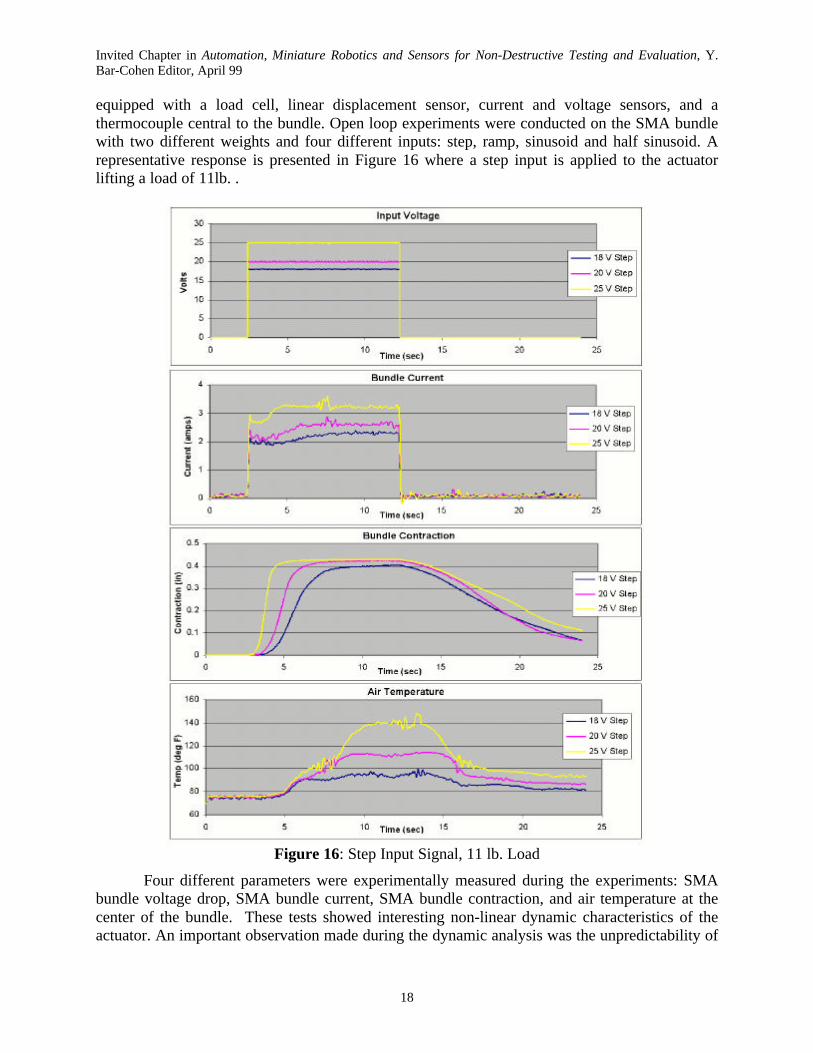
equipped with a load cell, linear displacement sensor, current and voltage sensors, and athermocouple central to the bundle. Open loop experiments were conducted on the SMA bundlewith two different weights and four different inputs: step, ramp, sinusoid and half sinusoid. Arepresentative response is presented in Figure 16 where a step input is applied to the actuatorlifting a load of 11lb. .
Figure 16: Step Input Signal, 11 lb. Load
Four different parameters were experimentally measured during the experiments: SMAbundle voltage drop, SMA bundle current, SMA bundle contraction, and air temperature at thecenter of the bundle. These tests showed interesting non-linear dynamic characteristics of theactuator. An important observation made during the dynamic analysis was the unpredictability of
Invited Chapter in Automation, Miniature Robotics and Sensors for Non-Destructive Testing and Evaluation, Y.Bar-Cohen Editor, April 99
19
the actuator's response when low to moderate voltages are applied. This characteristic stronglysuggests chaotic behavior of the actuator, which could potentially cause control difficulties infine and high accuracy tasks. An investigation into chaos was conducted using time histories,phase plots, and Poincaré maps [Mosley and Mavroidis, 1999]. As it was shown in this paper,system response to larger input voltages is periodic, whereas lower input voltages produceresponses that strongly indicate chaotic behavior.
5.1.3.5 Modeling, Dynamics, and Control of Shape Memory Alloy Actuators
Developing a mathematical model that captures the behavior of a Shape Memory Alloyas it undergoes temperature, stress, and phase changes is a complicated and challenging problem.Researchers continue to study how best to model and control actuators that use this uniquefamily of materials. As discussed earlier, it is the significant hysteresis loop that causes theproblems. Gorbet and Wang, 1998, provide an excellent summary of SMA actuator modelingefforts to date. Some researchers have chosen to greatly simplify the material's behavior bycreating dynamic model where the phase transition temperature is the same for heating andcooling, completely ignoring the effects of the large hysteresis. Kuribayashi, 1986, took the nextstep and developed a linear first-order model that estimates the hysteresis in the stress-strainbehavior.
To improve the accuracy, the model must be non-linear. The complete model mustcapture the major hysteresis loop that occurs for changes from 100% martensite to 100%austenite and vice versa as well as the minor hysteresis loops that occur in between. Minorhysteresis loops are inherent in position control systems where heating and cooling cycles backand forth as the control system holds the actuator at the desired position. Ikuta et al., 1991,developed a novel "variable sublayer model" where, at a given time, the percentages of thedifferent phases (including the intermediary Rhonbohedral phase) are mathematically described.As a result, for a given load, strain in the wire can be calculated from corresponding weightingsof the respective strains of the different phases. Ikuta's work provided a basis for all non-linearmodels to date. To fully understand Ikuta’s modeling process, one should consult [Ikuta et al.,1991]. A basic description is provided below.
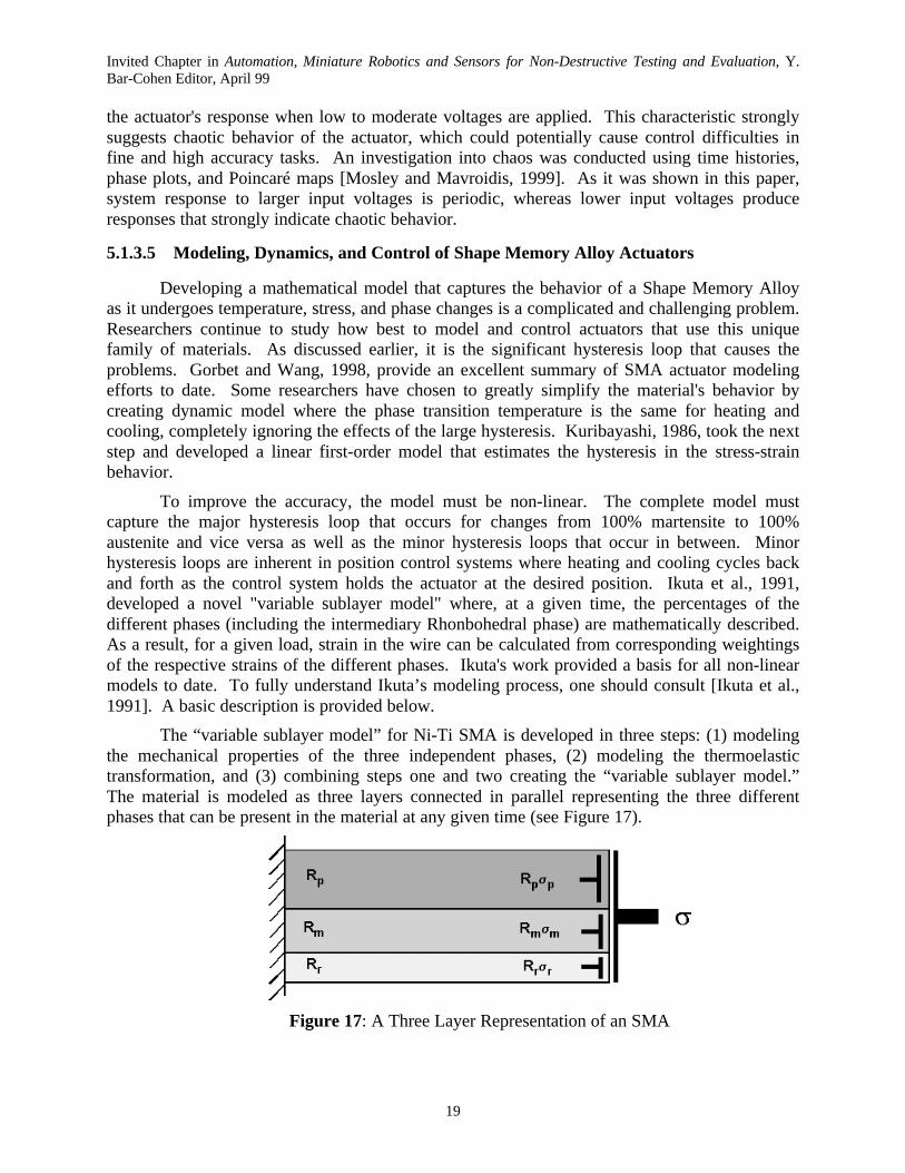
The “variable sublayer model” for Ni-Ti SMA is developed in three steps: (1) modelingthe mechanical properties of the three independent phases, (2) modeling the thermoelastictransformation, and (3) combining steps one and two creating the “variable sublayer model.”The material is modeled as three layers connected in parallel representing the three differentphases that can be present in the material at any given time (see Figure 17).
Figure 17: A Three Layer Representation of an SMA

Invited Chapter in Automation, Miniature Robotics and Sensors for Non-Destructive Testing and Evaluation, Y.Bar-Cohen Editor, April 99
20
The thickness of each layer corresponds to the volume fraction of the phase at a givenmoment. The total stress is a sum of the stresses in each layer weighted by the volume fraction.Resistivity of the material is modeled similar to stress – the total effective resistivity is the sumof the resistivities of each phase, each weighted by the volume fraction. Schematics of modelingthe mechanical properties are shown in Figure 18. The austenite phase (often referred to as theparent phase or P-phase) is modeled as a simple elastic body. The martensite phase (M-phase)and the Rhomohedral phase are both represented as a serial connection of an elastic and plasticelement. The thermoelastic transformation, including minor hysteresis loops, is mathematicallymodeled by a form of a “logistic curve” where the equation gives phase volume fraction as afunction of temperature and stress. Ikuta compared his model to experimental results andshowed greatly improved accuracy compared to previous models.
Figure 18: Models of Three Phases
Madill and Wang, 1998, developed extensions to the Ikuta’s variable sublayer model thatrefined the modeling of the minor hysteresis loops making it more suitable for dynamicallymodeling position control systems where electricity is the source of heating. Their modelconsisted of two key elements – a temperature-current and a strain-temperature relationship. Thetemperature-current relationship was used to capture the dynamics of a Ni-Ti SMA actuator.The form of this relationship is a differential equation in terms of temperature, electrical current,and time:
))(()(2∞−−= TtThAtRi
dt
dTcVρ (5)
Where: ρ is the density of SMA material, c is the specific heat capacity of SMA material, V isthe volume of SMA material, T is the wire temperature, t is the time, I is the current, R is theelectrical resistance, h is the convection heat transfer coefficient, A is the surface area of SMAmaterial, T is the ambient temperature.
The strain-temperature relationship, used to model hysteresis, involves two steps. Firsttemperature and stress must be related to phase composition. Second phase composition to mustbe related to strain. The resulting equations are somewhat lengthy and one must consultreference [Madill and Wang, 1998] for a full explanation. The first step, relating temperatureand stress to volume fraction of martensite, takes the following form:

Invited Chapter in Automation, Miniature Robotics and Sensors for Non-Destructive Testing and Evaluation, Y.Bar-Cohen Editor, April 99
21
++
++
=
−
−
heatingwhentRe
tR
coolingwhentRe
tR
tRHmbk
Hma
Cmk
Cma
m
HHm
CCm
,)(]1[
)(
,)(]1[
)(
);(
)(
)(
βθ
βθ
θ (6)
where Rm is the martensite fraction; θ is the difference between the wire temperature T and theambient temperature T∞; km is a temperature constant; Rma and Rmb are constants that define themartensite fraction at the beginning and the end of the minor loops; the superscripts C and Hdenote cooling and heating respectively. Temperature and stress enter the equations in theexponential terms. The four functions, R(t), are piecewise constant functions of time whichmodel the minor hysteresis loops. These functions remain constant during a period of heating orcooling. However, when a shift occurs from heating to cooling or vice versa, the functionschange. Here is where the primary difference occurs between this model and that of Ikuta.Ikuta’s modeling of minor hysteresis loops relied on empirically determining constantparameters for each minor loop, instead of time varying functions, making it unsuitable formodeling closed loop control systems where minor loops are occurring continuously. Thesecond step, relating phase composition to strain, takes the following form:
<−−
−+−+
<≤−−−+
<≤−−
=
εεεεσ
εεεεσ
εεσ
ε
dm
mdaa
dmTd
ymmTm
dm
ym
mTaa
ymmTm
ym
mmaa
REEE
EEEER
REEE
EER
REEE
,])([
])()[(
,])([
)(
0,])([
(7)
where ε is the tensile strain; σ is the tensile load (Mpa); σa and σm stress [Mpa] due to 100%austenite and martensite respectively; Ea, Em, ET, Ed, the elasticity [Mpa] of austenite, fullytwinned martensite, partly twinned martensite and detwinned martensite; εm
y yield strain oftwinned martensite; εm
d minimum strain of detwinned martensite; Rm martensite fraction.
Madill and Wang, 1998, tested their model against results of both open and closed loopexperiments. The correlation between the model and the experimental results was excellent forthe open loop testing as well as for closed loop testing with a proportional gain controller. Thecorrelation was very close for a PI controlled closed loop experiment.
Very little work has been performed in the control of SMA actuated robotic systems. Thisis a very difficult problem to solve for three main reasons: a) SMA actuators present non-lineardynamics where classical linear controllers can not be used; b) the response of the system ishighly dependent on temperature changes; and c) the SMA actuators present an unpredictabilityin small voltages. This sensitivity in initial condition at low inputs, suggest chaotic behaviorwhich means that if high accuracy tasks are needed, then conventional controllers won’t be ableto achieve the desired accuracies. Nevertheless, there were some very important results afterapplying several controllers. Classical PI, PD and PID controllers have been studied by [Madilland Wang, 1998; Reynaerts and Van Brussel, 1991; Ikuta et al., 1988]. A PI controller includinga temperature feedback has been studied by [Troisfotaine, Bidaud and Dario, 1997]. A variablestructure controller has been studied by [Grant 1995; Grant and Hayward, 1997].
Invited Chapter in Automation, Miniature Robotics and Sensors for Non-Destructive Testing and Evaluation, Y.Bar-Cohen Editor, April 99
22
5.1.4 ELECTRO-RHEOLOGICAL FLUIDS (ERF)
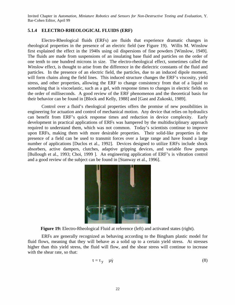
Electro-Rheological fluids (ERFs) are fluids that experience dramatic changes inrheological properties in the presence of an electric field (see Figure 19). Willis M. Winslowfirst explained the effect in the 1940s using oil dispersions of fine powders [Winslow, 1949].The fluids are made from suspensions of an insulating base fluid and particles on the order ofone tenth to one hundred microns in size. The electro-rheological effect, sometimes called theWinslow effect, is thought to arise from the difference in the dielectric constants of the fluid andparticles. In the presence of an electric field, the particles, due to an induced dipole moment,will form chains along the field lines. This induced structure changes the ERF’s viscosity, yieldstress, and other properties, allowing the ERF to change consistency from that of a liquid tosomething that is viscoelastic, such as a gel, with response times to changes in electric fields onthe order of milliseconds. A good review of the ERF phenomenon and the theoretical basis fortheir behavior can be found in [Block and Kelly, 1988] and [Gast and Zukoski, 1989].
Control over a fluid’s rheological properties offers the promise of new possibilities inengineering for actuation and control of mechanical motion. Any device that relies on hydraulicscan benefit from ERF’s quick response times and reduction in device complexity. Earlydevelopment in practical applications of ERFs was hampered by the multidisciplinary approachrequired to understand them, which was not common. Today’s scientists continue to improveupon ERFs, making them with more desirable properties. Their solid-like properties in thepresence of a field can be used to transmit forces over a large range and have found a largenumber of applications [Duclos et al., 1992]. Devices designed to utilize ERFs include shockabsorbers, active dampers, clutches, adaptive gripping devices, and variable flow pumps[Bullough et al., 1993; Choi, 1999 ]. An engineering application of ERF’s is vibration controland a good review of the subject can be found in [Stanway et al., 1996].
Figure 19: Electro-Rheological Fluid at reference (left) and activated states (right).
ERFs are generally recognized as behaving according to the Bingham plastic model forfluid flows, meaning that they will behave as a solid up to a certain yield stress. At stresseshigher than this yield stress, the fluid will flow, and the shear stress will continue to increasewith the shear rate, so that:
γµ+τ=τ &y (8)

Invited Chapter in Automation, Miniature Robotics and Sensors for Non-Destructive Testing and Evaluation, Y.Bar-Cohen Editor, April 99
23
where: τ is the shear stress, τy is the yield stress, µ is the dynamic viscosity and γ is the shearstrain. The dot over the shear strain indicates its time derivative, the shear rate. In general, boththe yield stress and the viscosity will be functions of the electric field strength.
An example of an ERF is the electro-rheological fluid LID 3354, manufactured by ERFluid Developments Ltd., will be used [ER Fluids Developments Ltd, 1998]. LID 3354 is anelectro-rheological fluid made up of 35% by volume of polymer particles in fluorosilicone baseoil. It is designed for use as a general-purpose ER fluid with an optimal balance of criticalproperties and good engineering behavior. Solid and liquid are density matched to minimizesettling. LID 3354 can be used in suitable equipment wherever electronic control of mechanicalproperties is required, such as in controlled dampers, actuators, clutches, brakes and valves. Itsphysical properties are: density: 1.46 x 10³ kg/m3; viscosity: 125 mPa.sec at 30°C; boiling point:> 200°C; flash point: >150°C; insoluble in water; freezing point: < -20°C.
The field dependencies for this particular ERF are:
( )os,y EEC −=τ 2d,y AE=τ 2
o BE−µ=µ (9)
where: µο is the zero field viscosity; A, B, C and Eo are constants supplied by the manufacturerThe subscripts s and d correspond to the static and dynamic yield stresses. The formula for staticyield stress is only valid for fields greater than Eo. Figures 4 a, b, and c are a graphicalrepresentation of the last equations for the ERF LID 3354. Figure 4d shows the dependency ofthe current density at 30°C as a function of the field. Figure 4e shows the coefficient B ofEquation (2) as a function of the temperature.
0
1
2
3
4
5
6
7
8
9
0 1 2 3 4
Field, kV/mm
Yie
ld s
tres
s, k
Pa
0
0.5
1
1.5
2
2.5
3
3.5
4
4.5
0 1 2 3 4
Field, kV/mm
Yie
ld s
tres
s, k
Pa
-200
-150
-100
-50
0
50
100
150
0 1 2 3 4
Field, kV/mm
Pla
stic
vis
cosi
ty, m
Pa.
sec
(a) Static Yield Stress at 30°C (b) DynamicYield Stress at 30°C (c) Plastic Viscosity at 30°C
-2
0
2
4
6
8
10
12
0 1 2 3 4
Field, kV/mm
Cu
rren
t D
ensi
ty,
mic
roA
/sq
.cm
0
0.05
0.1
0.15
0.2
0.25
0.3
0.35
0.4
-20 0 20 40 60 80
Temperature, °C
A,
kPa.
mm
2/kV
2
(d) Current Density at 30°C (e) Temperature Dependence of B,
Figure 20: Technical Information Diagrams for the ER Fluid LID 3354[Published by Permission of ER Fluids Development Ltd]

Invited Chapter in Automation, Miniature Robotics and Sensors for Non-Destructive Testing and Evaluation, Y.Bar-Cohen Editor, April 99
24
The application of ERF’s in robotic and haptic systems has been very limited. They havemainly been used as active dampers for vibration suppression [Furusho et al., 1997; Takesue etal., 1999]. In Virtual Reality and Haptic Systems, Electrorheological fluids have been proposedas tactile arrays to emulate the stiffness of remote/virtual objects [Taylor et al., 1996; Monkman,1992]. Possible applications that have been considered are training purposes and Braille systemsfor the blind. Relatively large forces, small size, light weight and high bandwidth are theadvantages of ERF's that make them very good candidates as actuators in robotic and hapticsystems. However, there are two main disadvantages with these actuators that any designershould take into account: a) large voltages are required to produce the output forces and b) theseactuators can only be used to emulate stiffness. This means that the output force is obtained as areaction to an input force from a human operator or the environment. ERF's can not be used toapply "push" forces that will result in motion of a system.
5.1.5 REFERENCES
Binnard, M., 1995, Boadicea: A Small Pneumatic Walking Robot, Master of Science Thesis,Artificial Intelligence Laboratory, MIT.
Block, H. and Kelly, J. P., 1988, “Electro-Rhehology”, Journal of Physics, D: Applied Physics,Vol. 21, pp. 1661.
Bullough, W. A., Johnson, A. R., Hosseini-Sianaki, A., Makin, J. and Firoozian, R., 1993,“Electro-Rheological Clutch: Design, Performance Characteristics and Operation,” Proceedingsof the Institution of Mechanical Engineers, Part I, Journal of Systems and Control Engineering,Vol. 207, No. 2, pp. 87-95.
Burdea, G., 1996, Force and Touch Feedback for Virtual Reality, John Wiley & Sons, Inc.
Choi, Seung-Bok, 1999, "Vibration Control of a Flexible Structure Using ER Dampers,"Transactions of the ASME, Journal of Dynamic Systems, Measurement and Control, Vol. 121,pp. 134-138.
Dimarogonas, A., 1993, “The Origins of Machines and Mechanisms,” in Modern Kinematics,Developments in the Last Forty Years, Edited by Erdman, A., John Wiley and Sons.
Duclos, T., Carlson, J., Chrzan, M. and Coulter, J. P., 1992, “Electrorheological Fluids –Materials and Applications,” in Intelligent Structural Systems, Tzou and Anderson (editors),Kluwer Academic Publishers, pp. 213-241, Netherlands.
ER Fluids Developments Ltd, 1998, “Electro-Rheological Fluid LID 3354,” TechnicalInformation Sheet, United Kingdom.
Furusho J., Zhang G. and Sakaguchi M., 1997, “Vibration Suppression Control of Robot ArmsUsing a Homogeneous-Type Electrorheological Fluid,” Proceedings of the 1997 IEEEInternational Conference on Robotics and Automation, Albuquerque, NM, pp. 3441-3448.
Gast, A. P., and Zukoski, C. F., 1989, “Electrorheological Suspensions as ColloidalSuspensions,” Advances in Colloid and Interface Science, Vol. 30, pp. 153.
Gorbet, R., and Wang, D., 1998, “A Dissipativity Approach to Stability of a Shape MemoryAlloy Position Control System”, IEEE Transactions on Control Systems Technology, Vol. 6, No.4, pp. 554-562.
Invited Chapter in Automation, Miniature Robotics and Sensors for Non-Destructive Testing and Evaluation, Y.Bar-Cohen Editor, April 99
25
Grant, D., 1995, Shape Memory Alloy Actuator with an Application to a Robotic Eye,Department of Electrical Engineering Thesis, McGill University, CA.
Grant, D. and Hayward, V., 1997, “Variable Structure Control of Shape Memory AlloyActuators”, IEEE Control Systems Magazine, Vol. 17, No. 3, pp. 80 – 88.
Henkenius, M., 1991, Electric Motor, Popular Mechanics, December 1991.
Hirose, S., Ikuta, K., and Umetani, Y., 1984, “A New Design Method of Servo-actuators Basedon the Shape Memory Effect”, Theory and Practice of Robots and Manipulators, Proc. ofRoManSy 1984, The Fifth CISM-IFToMM Symposium, The MIT Press, Cambridge, MA.
Hirose, S., Ikuta, K. and Umetani, Y., 1989a, "Development of a Shape Memory AlloyActuators. Performance Assessment and Introduction of a New Composing Approach,"Advanced Robotics, Vol. 3, No. 1, pp. 3-16.
Hirose, S., Ikuta, K., and Sato, K., 1989b, "Development of a Shape Memory Alloy Actuator.Improvement of the Output Performance by the Introduction of a σ-Mechanism", AdvancedRobotics, Vol. 3, No. 2, pp. 89-108, VSP and Robotics Society of Japan.
Hodgson, D., Wu, M. and Biermann, R., 1998, Shape Memory Alloys, http://www.sma-inc.com/SMAPaper.html.
Hollerbach, J., Hunter, I. and Ballantyne, J., 1992, “A Comparative Analysis of ActuatorTechnologies for Robotics,” in O. Khatib, J. Craig and Losano-Perez Eds., The Robotics Review2, MIT Press, Cambridge, MA, pp. 299-342.
Honma, D., Yoshiyuki, M., and Igushi, N., 1989, "Micro Robots and Micro Mechanisms UsingShape Memory Alloy," Integrated Micro Motion Systems. Micro-machining, Control andApplication, Nissin, Aichi, Japan, The 3rd Toyota Conference.
Ikuta, K., Tsukamoto, M., and Hirose, S., 1988, “Shape Memory Alloy Servo Actuator SystemWith Electric Resistance Feedback and Application for Active Endoscope”, Proc. of the 1988IEEE International Conference on Robotics and Automation, Vol. 1., Computer Society Press,Washington, DC.
Ikuta, K., Tsukamoto, M., and Hirose, S., 1991, “Mathematical Model and ExperimentalVerification of Shape Memory Alloy for Designing Micro Actuator”, Proc. of the IEEE onMicro Electromechanical Systems, an Investigation of Microstructures, Sensors, Actuators,Machines, and Robots, pp.103-108.
Kuribayashi, K., 1986, “A New Actuator of a Joint Mechanism Using Ti-Ni Alloy Wire”, TheInternational Journal of Robotics Research, Vol.4, No. 4, pp. 47-58.
Madill, D. and Wang, D., 1998, “Modeling and L2-Stability of a Shape Memory Alloy PositionControl System”, IEEE Transactions on Control Systems Technology, Vol. 6, No. 4, pp. 473-481.
Monkman, G. J., 1992, "Electrorheological Tactile Display", Presence, MIT Press, Vol. 1, No. 2.
Mosley, M., Mavroidis, C., and Pfeiffer, C., 1999, “Design and Dynamics of a Shape MemoryAlloy Wire Bundle Actuator”, Proc. Of the ANS, 8th Topical Meeting on Robotics and remoteSystems, Pittsburgh, PA.
Invited Chapter in Automation, Miniature Robotics and Sensors for Non-Destructive Testing and Evaluation, Y.Bar-Cohen Editor, April 99
26
Mosley M. and Mavroidis C., 1999, “Experimental Non-Linear Dynamics of a Shape MemoryAlloy Wire Bundle Actuator", submitted for publication in the Proc. of the 1999 ASME Int.Mech. Eng. Congress and Exposition, Dyn., Measurement and Control Division, Nashville, TE.
Reynaerts, D. and Van Brussel, H., 1991, "Development of a SMA High Performance RoboticActuator," Proceedings of the Fifth International Conference on Advanced Robotics, Vol. 2, pp.19-27, New York, NY.
Rosheim, M., 1994, Robot Evolution: The Development of Anthrobotics, John Wiley & Sons.Inc.
Schilling, 1999, http://www.schilling.com .
Spong, M., and Vidyasagar, M., 1989, Robot Dynamics and Control, John Willey & Sons.
Stadler, W., 1995, Analytical Robotics and Mechatronics, McGraw-Hill, New York.
Stanway, R., Sproston, J. L., and El-Wahed, A. K., 1996, “Applications of Electro-RheologicalFluids in Vibration Control: A Survey,” Smart Materials and Structures, Vol. 5, No. 4, pp. 464-482.
Stewart, H., 1987, Pneumatics and Hydraulics, revised by Tom Phibin, Macmillan PublishingCompany, New York, 4th Edition.
Takesue, N., Zhang, G., Furusho, J. and Sakaguchi, M., 1999, "Precise Position Control of RobotArms Using a Homogeneous ER Fluid," IEEE Control Systems Magazine, April 1999, pp. 55-61.
Taylor, P. M., Hosseini-Sianaki, A. and Varley, C. J., 1996, "Surface Feedback for VirtualEnvironment Systems Using Electrorheological Fluids," International Journal of ModernPhysics B, Vol. 10, Nos 23 & 24, pp. 3011-3018.
Toki Corporation, 1987, Biometal Guidebook, Tokyo, Japan.
Troisfontaine, N., Bidaud, P. and Dario, P., 1997, "Control Experiments on Two SMA BasedMicro-Actuators," Proceedings of the Experimental Robotics (ISER 97), Barcelona, Spain.
Waram, T., 1993, Actuator Design Using Shape Memory Alloys, 2nd Edition.
Winslow, W. M., 1949, “Induced Fibrillation of Suspensions,” Journal of Applied Physics, Vol.20, pp. 1137.
Zeldman, M., 1984, What Every Engineer Should Know About Robots, Marcel Dekker, Inc. .