actuators & valve - nutorknutork.com/product/17-ball valve, iso5211 direct mounted-en.pdf ·...
TRANSCRIPT

NUTORK CORPORATION
Ball Valve
Actuators & Valve
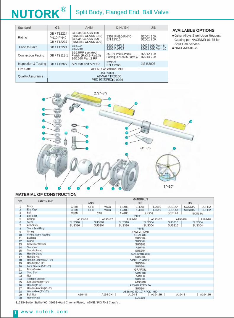
Split Body, Flanged End, Ball Valve
AVAILABLE OPTIONS
MATERIAL OF CONSTRUCTION
Other Alloys Steel Upon Request.Casting per NACE/MR-01-75 for Sour Gas Service.NACE/MR-01-75
1
GB ANSI DIN / EN JIS
GB / T12224PN10-PN40GB / T12237
NO. PART NAME
BodyEnd Cap BallBall Seat Bolting Stem Anti-Static Stem Seal-Ring O-ring V-Ring Stem PackingBushing GlandBelleville WasherStem Nut Stop-lock-cap Handle Gland Handle NutHandle Sleeve(1/2”~3”)Handle(1/2”~3”)Lock Device (1/2”~3”)Body Gasket Stop BlotNut Triangle Stooper Set Screwed(4”~6”)Handle(4”~6”)Handle Adapter(4”~6”)Worm Gear(8”~10”)Bolt Nut Name Plate
316SS+Solder Stellite #6, 316SS+Hard Chrome Plated, ASME / PCI 70-2 Class V .
123456789101112131415161718192021222324252627282930
ANSI CF8MCF8MCF8M
SUS316SUS316
SUS304SUS304
SUS304SUS304
PTFEFKM(VITION)
GRAFOILSUS304SUS304SUS301A194-8SUS304
SUS304(Black)SUS304
VINYL PLASTICSUS304SUS304
GRAFOILA193-B8A194-8SUS304A193-B8
A53+PLATED ZnSUS304
A536 (60-50-12) / FCD 450
SUS304SUS304
SUS316SUS316
SUS316SUS316
A194-8 A194-2H A194-2H A194-2HA194-8SUS304
A194-8
A193-B8 A193-B7 A193-B8PTFE
A193-B7 A193-B8 A193-B7
CF8CF8
CF8
WCBWCB
1.44081.44081.4408
1.43081.4308
1.4308
1.06191.0619
SCS14ASCS14ASCS14A
SCS13ASCS13A
SCS13A
SCPH2SCPH2
DIN JIS MATERIALS
GB / T12221
GB / T9113.1
GB / T13927
Standard
Rating
Inspection & Testing Fire Safe
Quality Assurance
Face to Face
Connection Facing
B16.34 CLASS 150(BS5351 CLASS 150)B16.34 CLASS 300(BS5351 CLASS 300)
3357 PN10-PN40EN 12516
B2001 10KB2001 20K
B2002 10K Form 6B2002 20K Form 10
B2212 10KB2214 20K
JIS B2003
3202 F4/F183202 F1/F17
2501/1 PN10-PN40Facing DIN 2526 Form C
3230/3EN 12266
B16.10BS2080B16.5RF serratedFinish (Ra3.2-Ra6.3)BS1560 Part 2 RF
API 598 and API 6D
API 607 4th edition 1993ISO 9001
AD-W0 / TRD1000036PED 97/23/EC 0036PED 97/23/EC
(1/2”~3”)
(4”~6”)
8”~10”
17 18
1918
18
15
14
13
12
11
10
22
21 29
26
27
25
24
28
30
20
9
8
6
1 4
7
3 4 2 5

2
Nutork soft-seated ball valves conform to Fire Tests of API 607 Fourth Edition and BS 6755 Part 2 (1987). Our products can
seal properly during the fire and after the accident, reduce indisde and outside leakage of pipeline fluids, and prevent
environmental pollution (even the fire) resulted from flammable or other fluids in the pipeline.
Design Features:1. During the fire, soft seats (such as PTFE, RTFE... etc) will burn up and lose supporting and sealing functions. Then, the
Ball free moves downstream due to pressure from upstream, contacts secondary metal seats of Body or End Cap, and
finally achieves to prevent leakage (see flgures #1 & #2).
2. Grafoil Body Gaskets can endure high temperature and remain unaffected during the fire, and eventually prevent fluid
leakage to the exterior. Moreover, the connection of Body and End Cap Flange maintains metal to metal contact by Stud
Bolts screwed into Body (see figures #3 & #4).
3. Grafoil Stem Seals can endure high temperature and remain unaffected during the fire and prevent fluid leakage to the
exterior (see figures #5 & #6).
#5 BEFORE FIRE #6 AFTER FIRE
V-RING PACKING
BODY GASKET
STEM SEAL-RING
BALL SEAT
#3 BEFORE FIRE #4 AFTER FIRE
GRAFOIL BODY GASKET
#1 BEFORE FIRE #2 AFTER FIRE
METAL TO METAL CONTACT
GRAFOIL V-RING PACKING
Split Body, Flanged End, Ball Valve
API607- 5th
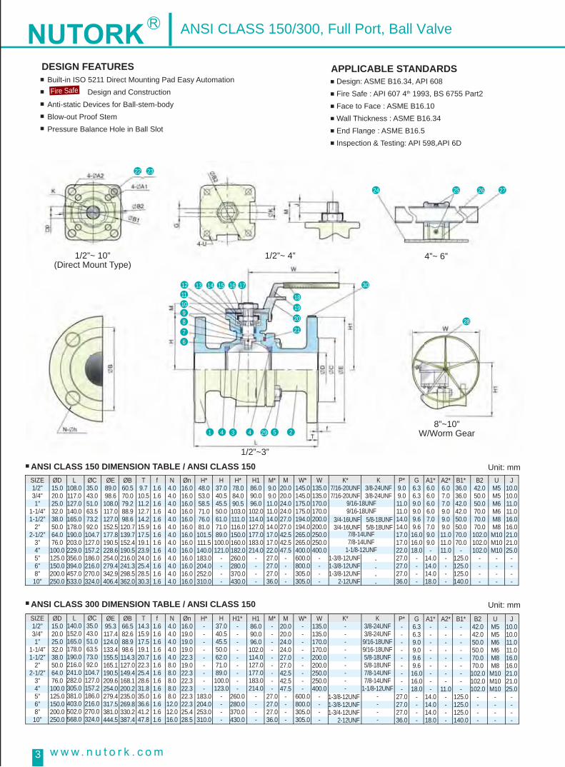
ANSI CLASS 150 DIMENSION TABLE / ANSI CLASS 150
3
SIZE1/2”3/4”1”
1-1/4”1-1/2”
2”2-1/2”
3”4”5”6”8”
10”
ØD15.020.025.032.038.050.064.076.0100.0125.0150.0200.0250.0
SIZE1/2”3/4”1”
1-1/4”1-1/2”
2”2-1/2”
3”4”5”6”8”
10”
ØD15.020.025.032.038.050.064.076.0100.0125.0150.0200.0250.0
ØC35.043.051.063.573.292.0104.7127.0157.2186.0216.0270.0324.0
ØE89.098.6108.0117.0127.0152.5177.8190.5228.6254.0279.4342.9406.4
ØB60.570.079.288.998.6120.7139.7152.4190.5216.0241.3298.5362.0
Øn16.016.016.016.016.016.016.016.016.016.016.016.016.0
H*48.053.058.571.076.081.0101.5111.5140.0183.0204.0252.0310.0
H*78.084.090.5103.0111.0116.0150.0160.0182.0260.0280.0370.0430.0
M*9.09.011.011.014.014.017.017.022.027.027.027.036.0
W*145.0145.0175.0175.0194.0194.0265.0265.0400.0600.0800.0305.0305.0
P*9.09.011.011.014.014.017.017.022.027.027.027.036.0
G6.36.39.09.09.69.616.016.018.0
----
A1*6.06.06.06.07.07.09.09.0-
14.014.014.018.0
B1*36.036.042.042.050.050.070.070.0
-125.0125.0125.0140.0
B242.050.050.070.070.070.0102.0102.0102.0
----
UM5M5M6M6M8M8M10M10M10
----
J10.010.011.011.016.016.021.021.025.0
----
A2*6.07.07.09.09.09.011.011.011.0
----
P*---------
27.027.027.036.0
G6.36.39.09.09.69.616.016.018.0
----
A1*---------
14.014.014.018.0
B1*---------
125.0125.0125.0140.0
B242.042.050.050.070.070.0102.0102.0102.0
----
UM5M5M6M6M8M8M10M10M10
----
J10.010.011.011.016.016.021.021.025.0
----
A2*--------
11.0----
K*7/16-20UNF7/16-20UNF
3/4-16UNF3/4-16UNF
5/8-18UNF5/8-18UNF
K3/8-24UNF3/8-24UNF
K*---------
K3/8-24UNF3/8-24UNF9/16-18UNF9/16-18UNF5/8-18UNF5/8-18UNF7/8-14UNF7/8-14UNF
1-1/8-12UNF----
9/16-18UNF9/16-18UNF
7/8-14UNF7/8-14UNF
1-1/8-12UNF1-3/8-12UNF1-3/8-12UNF1-3/8-12UNF
2-12UNF
1-3/8-12UNF1-3/8-12UNF1-3/4-12UNF
2-12UNF
----
W135.0135.0170.0170.0200.0200.0250.0250.0400.0
----
M20.020.024.024.027.027.042.542.547.5
----
H186.090.096.0102.0114.0127.0177.0183.0214.0
----
H37.040.545.550.061.071.089.0100.0121.0
----
T9.710.511.212.714.215.917.519.123.924.025.428.530.3
f1.61.61.61.61.61.61.61.61.61.61.61.61.6
N4.04.04.04.04.04.04.04.04.04.04.04.04.0
ØE95.3117.4124.0133.4155.5165.1190.5209.6254.0279.4317.5381.0444.5
ØB66.582.688.998.6114.3127.0149.4168.1200.2235.0269.8330.2387.4
Øn16.019.019.019.022.319.022.322.322.322.322.325.428.5
H*---------
183.0204.0253.0310.0
H1*---------
260.0280.0370.0430.0
M*---------
27.027.027.036.0
W*---------
600.0800.0305.0305.0
W135.0135.0170.0170.0200.0200.0250.0250.0400.0
----
M20.020.024.024.027.027.042.542.547.5
----
H186.090.096.0102.0114.0127.0177.0183.0214.0
----
H37.040.545.550.062.071.089.0100.0123.0
----
T14.315.917.519.120.722.325.428.631.835.036.641.247.8
f1.61.61.61.61.61.61.61.61.61.61.61.61.6
N4.04.04.04.04.08.08.08.08.08.012.012.016.0
L108.0117.0127.0140.0165.0178.0190.0203.0229.0356.0394.0457.0533.0
ØC35.043.051.063.573.092.0104.7127.0157.2186.0216.0270.0324.0
L140.0152.0165.0178.0190.0216.0241.0282.0305.0381.0403.0502.0568.0
Unit: mm
ANSI CLASS 300 DIMENSION TABLE / ANSI CLASS 150 Unit: mm
DESIGN FEATURES APPLICABLE STANDARDS Design: ASME B16.34, API 608Fire Safe : API 607 4th 1993, BS 6755 Part2Face to Face : ASME B16.10Wall Thickness : ASME B16.34End Flange : ASME B16.5Inspection & Testing: API 598,API 6D
Built-in ISO 5211 Direct Mounting Pad Easy Automation Design and ConstructionAnti-static Devices for Ball-stem-bodyBlow-out Proof StemPressure Balance Hole in Ball Slot
Fire Safe
22 23
21
20
19
18
17161514131211109876
1 4 3 4 29 5 2
24
30
28
25 26 27
1/2”~3”
8”~10”W/Worm Gear
4”~ 6”1/2”~ 4”1/2”~ 10”(Direct Mount Type)
ANSI CLASS 150/300, Full Port, Ball Valve

Design Rating : EN 12516-1, ASME B16.34Fire Safe: API 607 4th 1993, BS 6755 Part2Face to Face : DIN 3202 F4/F17, F4/ F18, DIN 3357/2Wall Thickness : EN 12516-1End Flange: EN 1092-1: 1999; DIN 2545Inspection & Testing: EN 12266, API 6D
4
SIZEDN15DN20DN25DN32DN40DN50
DN65
DN80
DN100
DN125
DN150
DN200
DN250
200.0
250.0
400.0
450.0
550.0
650.0
65.0
76.0
100.0
125.0
150.0
170.0
180.0
190.0
325.0
350.0
290.0
310.0
350.0
400.0
450.0
122.0
138.0
185.0
200.0
145.0
160.0
3.0
3.0
3.0
3.0
3.0
8.0
8.0
8.0
12.0
8.0
8.0
18.0
18.0
101.5
111.5
140.0
183.0
204.0
89.0
100.0
121.0
-
-
150.0
160.0
182.0
260.0
280.0
177.0
183.0
214.0
-
-
17.0
17.0
22.0
27.0
27.0
42.5
42.5
47.5
-
-
250.0
250.0
400.0
-
-
17.0
17.0
22.0
27.0
27.0
16.0
16.0
18.0
-
-
9.0
9.0
-
14.0
14.0
11.0
11.0
11.0
-
-
70.0
70.0
-
125.0
125.0
102.0
102.0
102.0
-
-
21.0
21.0
25.0
-
-
M10
M10
M10
-
-
265.0
265.0
400.0
600.0
800.0
188.0
268.0 340.0 295.03.0 252.0 370.0
430.0
-
-
-
-
-
-
-
-
-
-
-
-
-
-
-
-
-
-
-
-
-
-
27.0
36.0
305.0
305.0
27.0
36.0
14.0
14.0
125.0
140.0310.0
24.0 22.0
26.03.0 12.0
320.0
PN ØD15.020.025.032.038.050.0
10/1625/4010/1625/4010/1625/4010/1625/4010/1625/40
1016254010162540
158.0162.0
220.0235.0250.0270.0285.0300.0
180.0190.0210.0220.0240.0250.0
18.026.022.026.0
18.025.0
212.0218.0
278.0285.0
360.0375.0395.0405.0425.0450.0
310.0320.0350.0355.0370.0385.0
30.034.0
26.030.022.026.030.033.0
32.038.0
335.0345.0
ØC45.058.068.078.088.0
102.0
ØE95.0
105.0115.0140.0150.0165.0
ØB65.075.085.0
100.0110.0125.0
Øn14.014.014.018.018.018.0
H*48.053.058.571.076.085.0
H37.040.046.050.061.071.0
H1*78.084.090.5
103.0111.0120.0
H186.090.096.0
102.0114.0127.0
M*9.09.011.011.014.014.0
W*145.0145.0175.0175.0194.0194.0
W135.0135.0170.0170.0200.0200.0
M20.020.024.024.027.027.0
f2.02.02.02.03.03.0
T16.018.018.018.018.020.018.022.020.024.020.024.022.026.022.028.0
N4.04.04.04.04.04.04.08.0
L115.0120.0125.0130.0140.0150.0
#L130.0150.0160.0180.0200.0230.0
P*9.09.011.011.014.014.0
G6.36.39.09.09.69.6
A1*6.06.06.06.07.07.0
B1*36.036.042.042.050.050.0
B242.042.050.050.070.070.0
UM5M5M6M6M8M8
J10.010.011.011.016.016.0
A2*6.06.07.07.09.09.0
DIN PN10/16/25/40 DIMENSION TABLE(F1/F17,F4/F18) Unit: mm
10162540
K*7/16-20UNF7/16-20UNF
3/4-16UNF3/4-16UNF
5/8-18UNF5/8-18UNF
K3/8-24UNF3/8-24UNF
9/16-18UNF9/16-18UNF
7/8-14UNF
7/8-14UNF
1-1/8-12UNF
1-3/8-12UNF
1-3/8-12UNF
1-3/4-12UNF
2-12UNF
22 23
24
17161514131211109876
30
28
18
19
20
21
25294341
25 26 27
DN15~DN80
DN200 ~ DN250W/Worm Gear
DN100 ~ DN150DN15 ~ DN100DN15 ~ DN250(Direct Mount Type)
DIN PN10/16/25/40, Full Port, Ball Valve
DESIGN FEATURES APPLICABLE STANDARDS Built-in ISO 5211 Direct Mounting Pad Easy Automation Design and ConstructionAnti-static Devices for Ball-stem-bodyBlow-out Proof StemPressure Balance Hole in Ball Slot
Fire Safe

K*---------
JIS 10K DIMENSION TABLE
5
Unit: mm
APPLICABLE STANDARDS Design : ASME B16.34, API 608Fire Safe : API 607 4th 1993, BS 6755 Part2Face to Face : JIS B2002 (ASME B16.10)End Flange: JIS B 2238Inspection & Testing: JIS B2003, API 6DWall Thickness : ASME B16.34
JIS 20K DIMENSION TABLE Unit: mm
22 23
24
17161514131211109876
30
28
18
19
20
21
25294341
25 26 27
15A ~ 80A
200A ~ 250AW/Worm Gear
100A ~ 150A15A ~ 100AA15 ~ 250A(Direct Mount Type)
SIZE15A20A25A32A40A50A65A80A100A125A150A200A250A
ØD15.020.025.032.038.050.064.076.0100.0125.0150.0200.0250.0
SIZE15A20A25A32A40A50A65A80A
100A125A150A200A250A
ØD15.020.025.032.038.050.064.076.0100.0125.0150.0200.0250.0
ØC51.056.067.076.081.096.0116.0126.0151.0182.0212.0262.0324.0
ØE95.0100.0125.0135.0140.0155.0175.0185.0210.0250.0280.0330.0400.0
ØB70.075.090.0100.0105.0120.0140.0150.0175.0210.0240.0290.0355.0
Øn15.015.019.019.019.019.019.019.019.023.023.023.025.0
H*48.053.063.570.071.080.0101.5111.5140.0183.0204.0252.0310.0
H*78.084.095.0103.0106.0116.0150.0160.0182.0260.0280.0370.0430.0
M*9.09.011.011.014.014.017.017.022.027.027.027.036.0
W*145.0145.0175.0175.0194.0194.0265.0265.0400.0600.0800.0305.0305.0
P*9.09.011.011.014.014.017.017.022.027.027.027.036.0
G6.36.39.09.09.69.616.016.018.0
----
A1*6.06.06.06.07.07.09.09.0-
14.014.014.018.0
B1*36.036.042.042.050.050.070.070.0
-125.0125.0125.0140.0
B242.050.050.070.070.070.0102.0102.0102.0
----
UM5M5M6M6M8M8M10M10M10
----
J10.010.011.011.016.016.021.021.025.0
----
A2*6.07.07.09.09.09.011.011.011.0
----
P*---------
27.027.027.036.0
G6.36.39.09.09.69.616.016.018.0
----
A1*---------
14.014.014.018.0
B1*---------
125.0125.0125.0140.0
B242.042.050.050.070.070.0102.0102.0102.0
----
UM5M5M6M6M8M8
M10M10M10
----
J10.010.011.011.016.016.021.021.025.0
----
A2*-------------
K*7/16-20UNF7/16-20UNF
3/4-16UNF3/4-16UNF
5/8-18UNF5/8-18UNF
K3/8-24UNF3/8-24UNF
K3/8-24UNF3/8-24UNF9/16-18UNF9/16-18UNF5/8-18UNF5/8-18UNF7/8-14UNF7/8-14UNF
1-1/8-12UNF----
9/16-18UNF9/16-18UNF
7/8-14UNF7/8-14UNF
1-1/8-12UNF1-3/8-12UNF1-3/8-12UNF1-3/8-12UNF
2-12UNF
1-3/8-12UNF1-3/8-12UNF1-3/4-12UNF
2-12UNF
----
W135.0135.0170.0170.0200.0200.0250.0250.0400.0
----
M20.020.024.024.027.027.042.542.547.5
----
H186.090.096.0102.0114.0127.0177.0183.0214.0
----
H37.040.046.050.061.071.089.0100.0121.0
----
T12.014.014.016.016.016.018.018.018.020.022.022.024.0
f1.01.01.02.02.02.02.02.02.02.02.02.02.0
N4.04.04.04.04.04.04.08.08.08.08.012.012.0
ØE95.0
100.0125.0135.0140.0155.0175.0200.0225.0270.0305.0350.0430.0
ØB70.075.090.0
100.0105.0120.0140.0160.0185.0225.0260.0305.0380.0
Øn15.015.019.019.019.019.019.023.023.025.025.025.027.0
H*---------
183.0204.0252.0310.0
H1*---------
260.0280.0370.0430.0
M*---------
27.027.027.036.0
W*---------
600.0800.0305.0305.0
W135.0135.0170.0170.0200.0200.0250.0250.0400.0
----
M20.020.024.024.027.027.042.542.547.5
----
H186.090.096.0102.0114.0127.0177.0183.0214.0
----
H37.040.545.550.062.071.089.0
100.0123.0
----
T14.016.016.018.018.018.020.022.024.026.028.030.034.0
f1.61.61.62.02.02.02.02.02.02.02.02.02.0
N4.04.04.04.04.08.08.08.08.08.0
12.012.012.0
L108.0117.0127.0140.0165.0178.0190.0203.0229.0356.0394.0457.0533.0
ØC51.056.067.076.081.096.0116.0132.0160.0195.0230.0275.0345.0
L140.0152.0165.0178.0190.0216.0241.0282.0305.0381.0403.0502.0568.0
JIS 10K/ 20K, Full Port, Ball Valve
DESIGN FEATURES Built-in ISO 5211 Direct Mounting Pad Easy Automation Design and ConstructionAnti-static Devices for Ball-stem-bodyBlow-out Proof StemPressure Balance Hole in Ball Slot
Fire Safe

Design Rating : GB / T12224 GB / T12237Fire Safe: API 607 4th 1993, BS 6755 Part2Face to Face : GB / T12221Wall Thickness: ASME B16.34End Flange:GB TT9113.1Inspection & Testing: GB / T13927 , API 598
6
GB-Q41F PN16 DIMENSION TABLE(F1/F17,F4/F18) Unit: mm
22 23
24
17161514131211109876
30
28
18
19
20
21
25294341
25 26 27
DN15~DN80
DN200 ~ DN250W/Worm Gear
DN100 ~ DN150DN15 ~ DN100DN15 ~ DN250(Direct Mount Type)
GB - Q41F PN10/16/25/40, Full Port, Ball Valve
DESIGN FEATURES APPLICABLE STANDARDS Built-in ISO 5211 Direct Mounting Pad Easy Automation Design and ConstructionAnti-static Devices for Ball-stem-bodyBlow-out Proof StemPressure Balance Hole in Ball Slot
Fire Safe
SIZEDN15DN20DN25DN32DN40DN50DN65DN80
DN100DN125DN150DN200DN250
ØD15.0 20.0 25.0 32.0 40.0 50.0 65.0 80.0 100.0 125.0 150.0 200.0 250.0
ØC45.0 58.0 68.0 78.0 84.0 99.0 118.0 132.0 156.0 184.0 211.0 266.0 319.0
ØE95.0 105.0 115.0 140.0 150.0 165.0 185.0 200.0 220.0 250.0 285.0 340.0 405.0
ØB65.0 75.0 85.0 100.0 110.0 125.0 145.0 160.0 180.0 210.0 240.0 295.0 355.0
Øn14.0 14.0 14.0 18.0 18.0 18.0 18.0 18.0 18.0 18.0 22.0 22.0 26.0
P9.0 9.0 11.0 11.0 14.0 14.0 17.0 17.0 22.0 27.0 27.0 27.0 36.0
G6.3 6.3 9.0 9.0 9.6 9.6 16.0 16.0 18.0
------------
A16.0 6.0 6.0 6.0 7.0 7.0 9.0 9.0 ---
14.0 14.0 14.0 14.0
B136.0 36.0 42.0 42.0 50.0 50.0 70.0 70.0
---125.0 125.0 125.0 140.0
B242.0 42.0 50.0 50.0 70.0 70.0 102.0 102.0 102.0
------------
UM5M5M6M6M8M8M10M10M10------------
J10.0 10.0 11.0 11.0 16.0 16.0 21.0 21.0 25.0
------------
A26.0 6.0 7.0 7.0 9.0 9.0 11.0 11.0 11.0 ------------
K3/8-24UNF3/8-24UNF9/16-18UNF9/16-18UNF5/8-18UNF5/8-18UNF7/8-14UNF7/8-14UNF
1-1/8-12UNF1-3/8-12UNF1-3/8-12UNF1-3/4-12UNF
2-12UNF
W135.0 135.0 170.0 170.0 200.0 200.0 250.0 250.0 400.0 600.0 800.0 305.0 305.0
M20.0 20.0 24.0 24.0 27.0 27.0 42.5 42.5 47.5 27.0 27.0 27.0 36.0
H186.0 90.0 96.0 102.0 114.0 127.0 177.0 183.0 214.0 260.0 280.0 370.0 430.0
H37.0 40.0 46.0 50.0 61.0 71.0 89.0 100.0 121.0 183.0 204.0 252.0 310.0
T14.0 16.0 16.0 16.0 18.0 20.0 20.0 20.0 22.0 22.0 24.0 24.0 26.0
f2.0 2.0 3.0 3.0 3.0 3.0 3.0 3.0 3.0 3.0 3.0 3.0 3.0
N4.0 4.0 4.0 4.0 4.0 4.0 4.0 8.0 8.0 8.0 8.0 12.0 12.0
L130.0 140.0 150.0 165.0 180.0 200.0 220.0 250.0 280.0 320.0 360.0 457.0 533.0
SIZEDN15DN20DN25DN32DN40DN50DN65DN80
DN100DN125DN150DN200DN250
ØD15.0 20.0 25.0 32.0 40.0 50.0 65.0 80.0 100.0 125.0 150.0 200.0 250.0
ØC45.0 58.0 68.0 78.0 84.0 99.0 118.0 132.0 156.0 184.0 211.0 284.0 315.0
ØE95.0 105.0 115.0 140.0 150.0 165.0 185.0 200.0 235.0 270.0 300.0 375.0 450.0
ØB65.0 75.0 85.0 100.0 110.0 125.0 145.0 160.0 190.0 220.0 250.0 320.0 385.0
Øn14.0 14.0 14.0 18.0 18.0 18.0 18.0 18.0 22.0 26.0 26.0 30.0 33.0
P9.0 9.0 11.0 11.0 14.0 14.0 17.0 17.0 22.0 27.0 27.0 27.0 36.0
G6.3 6.3 9.0 9.0 9.6 9.6 16.0 16.0 18.0
------------
A16.0 6.0 6.0 6.0 7.0 7.0 9.0 9.0 ---
14.0 14.0 14.0 14.0
B136.0 36.0 42.0 42.0 50.0 50.0 70.0 70.0
---125.0 125.0 125.0 140.0
B242.0 42.0 50.0 50.0 70.0 70.0 102.0 102.0 102.0
------------
UM5M5M6M6M8M8M10M10M10------------
J10.0 10.0 11.0 11.0 16.0 16.0 21.0 21.0 25.0
------------
A26.0 6.0 7.0 7.0 9.0 9.0 11.0 11.0 11.0 ------------
K3/8-24UNF3/8-24UNF9/16-18UNF9/16-18UNF5/8-18UNF5/8-18UNF7/8-14UNF7/8-14UNF
1-1/8-12UNF1-3/8-12UNF1-3/8-12UNF1-3/4-12UNF
2-12UNF
W135.0 135.0 170.0 170.0 200.0 200.0 250.0 250.0 400.0 600.0 800.0 305.0 305.0
M20.0 20.0 24.0 24.0 27.0 27.0 42.5 42.5 47.5 27.0 27.0 27.0 36.0
H186.0 90.0 96.0 102.0 114.0 127.0 177.0 183.0 214.0 260.0 280.0 370.0 430.0
H37.0 40.0 46.0 50.0 61.0 71.0 89.0 100.0 121.0 183.0 204.0 252.0 310.0
T14.0 16.0 16.0 16.0 18.0 20.0 22.0 24.0 24.0 26.0 28.0 34.0 38.0
f2.0 2.0 3.0 3.0 3.0 3.0 3.0 3.0 3.0 3.0 3.0 3.0 3.0
N4.0 4.0 4.0 4.0 4.0 4.0 4.0 8.0 8.0 8.0 8.0 12.0 12.0
L140.0 152.0 165.0 178.0 190.0 216.0 241.0 283.0 305.0 381.0 403.0 502.0 568.0
GB-Q41F PN40 DIMENSION TABLE(F1/F17,F4/F18) Unit: mm

7
ANSI CLASS 150 DIMENSION TABLE Unit: mm
ANSI CLASS 300 DIMENSION TABLE Unit: mm
MATERIAL OF CONSTRUCTION
PRESSURE VS TEMPERATURE CHART
PR
ES
SU
RE
IN P
SIG
PR
ES
SU
RE
IN B
AR
11001000
900800700600500400300200100
0-30
(-34)(-18) (38) (93) (194) (204) (260) (316)0 100 200 300 400 500 600
7669625548413428211470
1/4”~2”(PTFE / RTFE)
2-1/2”~6”(RTFE)
2-1/2”~6”(PTFE)
NO.12345
PART MATERIALBodyEnd Cap Ball Ball Seat Stem
CF8MCF8MCF8M
CF8CF8
WCBWCB
WCBPTFE
SUS 316 SUS 304PTFE / SUS 316 SPIRALWOUND * / GRAFOIL*PTFE / PTFE (+FKM*)
PTFE / GRAFOIL *50%SS+50%PTFE / SUS 304 *
SUS 316SUS 301SUS 304SUS 304SUS 304
VINYL PLASTICSUS 304SUS 304
A53-PLATED ZnA351-CF8SUS 304SUS 304
6
789101112131415161718192021
Body Gasket
Stem Seal-Ring(+O-Ring *) V-Ring Packing BushingGlandBelleville Washer Stem Nut Stop-Lock-Cap Handle (1”~3”)Handle Sleeve (1”~3”)Stop BoltSet Screwed (4”~6”)Handle (4”~6”)Handle Adapter (4”~6”)Lock Device (1/2”~3”)Triangle Stopper (4”~6”)
Ød15.020.025.032.038.050.064.076.0100.0125.0150.0
ØR35.043.050.863.573.592.0105.0127.0157.3186.0215.9
ØD89.098.6108.0117.4127.0152.4177.8190.5228.6254.0279.4
ØC60.570.079.388.998.6120.6139.7152.4190.5215.9241.3
ØB1424250507070
102102102102125
K3/8-24UNF3/8-24UNF9/16-18UNF9/16-18UNF5/8-24UNF5/8-24UNF7/8-14UNF7/8-14UNF11/8-12UNF13/8-12UNF13/8-12UNF
T9.710.511.212.714.315.817.519.023.925.225.4
f1.61.61.61.61.61.61.61.61.61.61.6
H41.044.046.555.064.073.188.097.0117.0155.0194.0
H190.594.099.099.0117.0124.0148.0157.0200.0270.0310.5
N44444444888
M1/2”1/2”1/2”1/2”1/2”5/8”5/8”5/8”5/8”3/4”3/4”
W135135170170200200250250280600800
G6.36.39.09.09.69.6
16.016.018.023.023.0
A17.017.022.724.025.823.942.542.651.476.576.5
J8.18.1
10.211.013.913.924.022.524.536.036.0
UM5M5M6M6M8M8
M10M10M10M10M12
L42.044.050.060.065.080.0110.0120.0150.0195.0225.0
SIZE1/2”3/4”1”
1-1/4”1-1/2”
2”2-1/2”
3”4”5”6”
Ød15.020.025.032.038.050.064.076.0100.0125.0150.0
ØR35.043.050.863.573.592.0105.0127.0140.3157.0186.0
ØD95.3117.4124.0133.0155.0165.0190.0210.0254.0280.0318.0
ØC66.582.688.998.6114.3127.0149.4168.1200.2235.0269.8
ØB1424250507070
102102102102125
K3/8-24UNF3/8-24UNF9/16-18UNF9/16-18UNF5/8-28UNF5/8-28UNF7/8-14UNF7/8-14UNF11/8-12UNF13/8-12UNF13/8-12UNF
T14.315.917.519.020.622.325.428.531.835.036.6
f1.61.61.61.61.61.61.61.61.61.61.6
H41.044.046.555.064.073.188.097.0117.0155.0194.0
H190.594.099.099.0117.0124.0148.0157.0200.0270.0310.5
N4444488888
12
M1/2”1/2”5/8”5/8”3/4”5/8”3/4”3/4”3/4”3/4”3/4”
W135135170170200200250250400600800
G6.36.39.09.09.69.6
16.016.018.023.023.0
A17.017.022.724.025.827.042.542.547.576.576.5
J8.18.1
10.211.013.913.924.022.524.536.036.0
UM5M5M6M6M8M8
M10M10M10M10M12
L42.044.050.060.065.080.0110.0120.0150.0195.0225.0
SIZE1/2”3/4”1”
1-1/4”1-1/2”
2”2-1/2”
3”4”5”6”
PR
ES
SU
RE
INP
SIG
ANSI CLASS 150 / 300, Full Port, Ball Valve
DESIGN FEATURESBuilt-in ISO 5211 Direct Mounting Pad Easy Automation Design and ConstructionAnti-static Devices for Ball-stem-bodyBlow-out Proof StemPressure Balance Hole in Ball Slot
Fire Safe
APPLICABLE STANDARDS Design : ASME B16.34, API 608Fire Safe : API 607 4th 1993, BS 6755 Part2Wall Thickness: ASME B16.34End Flange : ASME B16.5Inspection & Testing: API 598,API 6D
15
20
14
13
12
1110
9
8
7
6
5
4
32
1
7 Series FIRE-SAFE
1817
2119
4”~6”
16
1/2”~3”
* Materials For FIRE-SAFE Models
8
MATERIAL OF CONSTRUCTION
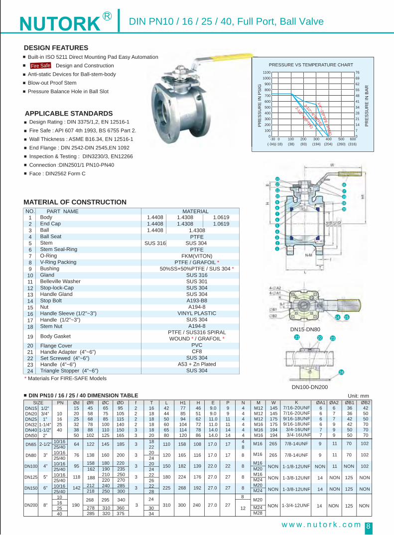
APPLICABLE STANDARDSDesign Rating : DIN 3375/1,2, EN 12516-1Fire Safe : API 607 4th 1993, BS 6755 Part 2.Wall Thickness : ASME B16.34, EN 12516-1End Flange : DIN 2542-DIN 2545,EN 1092Inspection & Testing : DIN3230/3, EN12266Connection :DIN2501/1 PN10-PN40Face : DIN2562 Form C
PRESSURE VS TEMPERATURE CHART
PR
ES
SU
RE
IN P
SIG
PR
ES
SU
RE
IN B
AR
11001000900800700600500400300200100
0-30
(-34)(-18) (38) (93) (194) (204) (260) (316)0 100 200 300 400 500 600
7669625548413428211470
1/4”~2”(PTFE / RTFE)
2-1/2”~6”(RTFE)
2-1/2”~6”(PTFE)
* Materials For FIRE-SAFE Models
DIN PN10 / 16 / 25 / 40 DIMENSION TABLE
Body End Cap BallBall Seat Stem Stem Seal-Ring O-Ring V-Ring Packing BushingGlandBelleville Washer Stop-lock-CapHandle Gland Stop Bolt Nut Handle Sleeve (1/2”~3”)Handle (1/2”~3”)Stem Nut
PART NAME MATERIAL 1.43081.4308
1.06191.0619
Body Gasket
Flange CoverHandle Adapter (4”~6”)Set Screwed (4”~6”)Handle (4”~6”)Triangle Stopper (4”~6”)
NO.123456789101112131415161718
19
2021222324
1.4308PTFE
PTFEFKM(VITON)
PTFE / GRAFOIL *50%SS+50%PTFE / SUS 304 *
SUS 316SUS 301SUS 304SUS 304A193-B8A194-8
VINYL PLASTICSUS 304A194-8
PTFE / SUS316 SPIRALWOUND * / GRAFOIL *
PVCCF8
SUS 304A53 + Zn Plated
SUS 304
SUS 304
1.44081.44081.4408
SUS 316
DN15DN20DN25DN32DN40DN50
DN65
DN80
DN100
DN125
DN150
DN200 8” 19024
3 310 300 240 27.0 2712 NON NON NON12514
268
158
2-1/2”
3”
4”
5”
6”
64
76
95
118
142
3
3
3
3
3
110
120
150
180
225
158
165
182
224
268
108
116
139
176
192
17.0
17.0
22.0
27.0
27.0
17
17
22
27
27
8
8
8
8
122
138
162
188
1/2”3/4”1”
1-1/4”1-1/2”
2”
10162540
10/1625/4010/1625/4010/1625/4010/1625/4010/1625/40
10162540
18222024202422262228
48
8
212218
278285
295 340
180 220
145
160
185
200
190210220240250
235250270285300
310320
360375
3034
SIZE PN Ød152025323850
ØR4558687888102
ØC657585100110125
ØD95105115140150165
f222233
T161818181820
L424450606580
H1778594
104114120
H465162727886
E9.09.011.011.014.014.0
P9911111414
N444444
MM12M12M12M16M16M16
M20M16M24M20M24
M24M28
W145145175175194194
K7/16-20UNF7/16-20UNF9/16-18UNF9/16-18UNF 3/4-16UNF 3/4-16UNF
ØA1666677
ØA2677999
ØB1363642425050
ØB2425050707070
102
102
102
NON
NON
70
70
NON
125
125
11
11
11
NON
NON
9
9
NON
14
14
265
265
NON
NON
NON
M16
M16
M16
M20
7/8-14UNF
7/8-14UNF
1-1/8-12UNF
1-3/8-12UNF
1-3/8-12UNF
1-3/4-12UNF
PR
ES
SU
RE
INP
SIG
DESIGN FEATURES Built-in ISO 5211 Direct Mounting Pad Easy Automation Design and ConstructionAnti-static Devices for Ball-stem-bodyBlow-out Proof StemPressure Balance Hole in Ball Slot
Fire Safe
DIN PN10 / 16 / 25 / 40, Full Port, Ball Valve
16
14
21 22 23
24
15
1817
19
20
1213
11
10
98
7
6
5
4
32
1
DN15-DN80
DN100-DN200Unit: mm

9
STANDARDS:
SPECIFICATIONS :
Design : ASME B16.34, API 608Wall Thickness : ASME B16.34 CLASS 400Pipe Thread :
Working Pressure : 1000 psing at 100°F (38°C)Temperature Range : -30°F to 350°F (-34°C to 177°C)
ASME B1.20.1, BS21DIN 2999/259, BSPISO 7/1, ISO 228/1JIS B 0203
ASME B16.25Ø B2 Available in Sch 10, 20 & 40
ASME B16.11ASME B16.5DIN2542~2545JISB2238
Butt Weld :
Socket Weld : Flange End :
Inspection & Testing : API 598 EN 12266
PRESSURE VS TEMPERATURE CHART
PR
ES
SU
RE
IN P
SIG
PR
ES
SU
RE
IN B
AR
11001000900800700600500400300200100
0-30
(-34)(-18) (38) (93) (194) (204) (260) (316)0 100 200 300 400 500 600
7669625548413428211470
RTFEPTFE
2 1/2”~4”
1/4”~2”
NO.1
PART MATERIAL
2
A351-CF8M(1.4408)A351-CF8M(1.4408)A351-CF3M(1.4408)A351-CF3M(1.4408)PTFEA193-B8A276-316SUS 316PTFEPTFE50%SS+50%PTFESUS 316SUS 301A194-8SUS 304SUS 304A194-8SUS 304SUS 304SUS 304SUS 304Vinyl PlasticFKM(VITON)A193-B8A194-8A193-B8SUS 304SUS 304SUS 304
Body Cap (Thread)Cap (Welding) Ball Ball Seat Bolt Stem Anti-StaticStem Seal-RingV-Ring Stem PackingBushingGland Belleville Washer Stem Nut Stop-Lock-Cap Bolt Washer Bolt Nut Handle GlandHandle Nut Lock Device Handle Handle Sleeve O-Ring Stop BoltNut Set Screwed Handle Handle Adapter Triangle Stopper
3456789
10111213141516171819202122232425262728
Unit: mm
FLANGE END (PN25/40 F1)
FLANGE BUTTWELD END
8
9
10 11 12 13 14 17 18 19 20 21 22
25 26 27
28
15 16
7
6
5
4
3
2
1
Ød10.612.715.020.025.032.038.050.063.576.0
100.0
L75.075.075.080.090.0110.0120.0140.0185.0205.0240.0
LE72727590100110125150190220270
LF----
130.0150.0160.0180.0200.0230.0290.0310.0350.0
H42.042.042.049.058.563.071.078.0100.0109.0140.0
H172.072.072.080.090.095.0106.0113.0150.0159.0198.0
ØE242.042.042.050.050.070.070.070.0102.0102.0102.0
ØU16.06.06.06.06.06.07.07.9.09.0--
ØU26.06.06.06.07.09.09.09.011.011.011.0
ØE136.036.036.036.042.042.050.050.070.070.0
--
ØD----
95.0105.0115.0140.0150.0165.0185.0200.0235.0
ØC----
65.075.085.0100.0110.0125.0145.0160.0190.0
ØR----
45.058.068.078.088.0102.0122.0138.0162.0
ØM----
14.014.014.018.018.018.018.018.022.0
ØB114.217.821.827.334.042.848.961.474.090.0115.4
ØB210.612.715.820.926.735.140.952.562.778.0102.4
ØB318.018.022.028.034.043.050.061.076.092.0115.0
ØDN
NPT
BSP
PT
NIN
etc.
T----
16.018.018.018.018.020.022.024.024.0
F----
2.02.02.02.03.03.03.03.03.0
N----
4.04.04.04.04.04.08.08.08.0
G9.09.09.09.011.011.014.014.017.017.022.0
A9.09.09.09.011.011.014.014.017.017.022.0
W145.0145.0145.0145.0160.0160.0190.0190.0260.0260.0350.0
SIZE1/4”3/8”1/2”3/4”1”
1-1/4”1-1/2”
2”2-1/2”
3”4”
3-PC 1000WOG Mounting Pad,Full Port Ball Valve
DESIGN FEATURES Built-in ISO 5211 Direct Mounting Pad Easy Automation Design and ConstructionAnti-static Devices for Ball-stem-bodyBlow-out Proof StemPressure Balance Hole in Ball Slot
Fire Safe
SUS 304Triangle Stopper 8
Unit: mm

10
NO.123456789101112131415161718192021
PART MATERIAL A351-CF8M(1.4408)A351-CF8M(1.4408)A351-CF3M(1.4408)TFM1600A193-B8A276-316SUS 316TFM1600PTFE50%SS+50%PTFESUS 316SUS 301A194-8SUS 304SUS 304Vinyl PlasticSUS 304SUS 304A194-8A193-B8PTFE
Body Thread Cap Ball Ball Seat BoltStem Anti-Static Stem Seal-Ring V-Ring Stem Packing Bushing Gland Belleville Washer Stem Nut Stop-Lock-Cap Handle (1/4”~3”)Handle Sleeve (1/4”~3”)Lock Device (1/4”~3”)Bolt Washer Bolt Nut Stop Bolt Body Gasket
Unit: mm
16
14
20
15
18
17
19
21
12 131110
9
8
7
6
5
4
3
2
1
DN
NPT
BSP
PT
DIN
etc.
3-PC 2000WOG Mounting Pad,Full Port Ball Valve
STANDARDS :
SPECIFICATIONS :
Design : ASME B16.34, API 608Wall Thickness : ASME B16.34 CLASS 800Pipe Thread :
Working Pressure : 1500 psing at 100°F (38°C)Temperature Range : -30°F to 350°F (-34°C to 177°C)
ASME B1.20.1, BS21DIN 2999/259, BSPISO 7/1, ISO 228/1JIS B 0203
ASME B16.25Ø B2 Available in Sch 10, 20 & 40
ASME B16.11ASME B16.5 CLASS 600DIN2542~2545 PN100JISB2238 40K
Butt Weld :
Socket Weld :Flange End :
Inspection & Testing : API 598 EN 12266
DESIGN FEATURES Built-in ISO 5211 Direct Mounting Pad Easy Automation Design and ConstructionAnti-static Devices for Ball-stem-bodyBlow-out Proof StemPressure Balance Hole in Ball Slot
Fire Safe
H30.030.036.039.545.550.060.068.0
L7070758090110120140
LB70707590100110125150
LE225225225225245255260275
LF----
130150160180200230
H17676838898103110119
W135135135135170175200200
ØE42.042.042.042.050.050.070.070.0
ØD----
95.3117.4124.0133.4155.5165.1
ØC----
66.682.688.998.6114.3127.0
ØR----
35.043.051.063.573.292.0
ØB114.018.022.027.534.543.048.661.2
ØB27.6
10.713.918.824.332.538.149.2
ØB318.018.022.228.034.043.050.061.0
Ød10.612.715.020.025.031.838.150.0
G6.36.36.36.39.09.09.69.6
UM5M5M5M5M6M6M8M8
T----
20.722.223.927.028.831.8
f----
6.356.356.356.356.356.35
N----444448
h----
15.819.119.119.122.419.1
A17.317.320.320.323.323.323.823.8
J10.410.411.811.812.512.515.115.1
L11111111313131316
SIZE1/4”3/8”1/2”3/4”1”
1-1/4”1-1/2”
2”

11
NO.123456789
101112131415161718192021222324
PART MATERIALA351 Gr. CF8MTFMTFM316L SSA351 Gr. CF3M304SS304SSPEEKViton 90316L SSTFM304SS304SS301SS304SS304SS304SS304SS304SS304SSVinyl316SS316SS316SS
End Cap Body Seal SeatBall Body Body Nut Body Bolt Thrust Washer Stem O-RingStem Stem Packing SetStop Pin Nut Packing Gland Belleville Washer Stem Nut Gland Nut Stop Pin Bolt Space Washer Handle Nut Handle Handle CoverFront Ferrule Back Ferrule Locking Nut
3-PC 2000WOG Mounting Pad,Full Port Tube End Ball Valve
STANDARDS :
SPECIFICATIONS :
Design : ASME B16.34, API 608Wall Thickness : ASME B16.34 CLASS 800Tube End :
Working Pressure : 1500 psing at 100°F (38°C)Temperature Range : -30°F to 350°F (-34°C to 177°C)
1/4” ~ 2”Inspection & Testing : API 598 EN 12266
DESIGN FEATURES Built-in ISO 5211 Direct Mounting Pad Easy Automation Design and ConstructionAnti-static Devices for Ball-stem-bodyBlow-out Proof StemPressure Balance Hole in Ball Slot
Fire Safe
O d2
O d1
O D3
O D2
O D1
S
6 7
A
O D4
DO
hH
M
20 21
11
10
9
8
17 1916 18
13
12
15
14
2 41 3 22 245 23
L
Size1/43/81/23/41
L86909999117
D1010101622
D1
1212121214
D2
1.421.421.421.421.65
D3
3636363642
D4
2525252530
d1
66667
d2
66666
H3939393948
h999911
s999911
DIMENSIONS

12
STANDARDS :
SPECIFICATIONS :
Design : ASME B16.34, API 608Wall Thickness : ASME B16.34 CLASS 400Pipe Thread :
Working Pressure : 1000 psing at 100°F (38°C)Temperature Range : -30°F to 350°F (-34°C to 177°C)
ASME B1.20.1, BS21DIN 2999/259, BSPISO 7/1, ISO 228/1JIS B 0203
Inspection & Testing : API 598 EN 12266
PRESSURE VS TEMPERATURE CHART
PRES
SUR
E IN
PSI
G
PRES
SUR
E IN
BAR
11001000
900800700600500400300200100
0-30
(-34)(-18) (38) (93) (194) (204) (260) (316)0 100 200 300 400 500 600
7669625548413428211470
RTFEPTFE
2 1/2”~3”
1/4”~2”
NO.12345678910111213141516171819202122
PART MATERIAL A351-CF8M(1.4408)A351-CF8M(1.4408)PTFEA351-CF8M(1.4408)A276-316SUS 316PTFEPTFE50%SS+50%PTFESUS 316SUS 301A194-8SUS 304SUS 304SUS 304SUS 304Vinyl PlasticSUS 304FKM (VITON)PTFEA193-B8A194-8
Body CapBall Seat Ball Stem Anti-Static Stem Seal-Ring V-Ring Stem Packing Bushing GlandBelleville Washer Stem Nut Stop-Lock-Cap Handle GlandHandle Nut Handle Handle Sleeve Lock Device O-Ring Body Gasket Stop Bolt Nut
Unit: mm
FLANGE END (PN25/40 F1)
8
9
10
11
12
13
1417
181920
21 22
1516
7
6
5
4
3
2
1
Ød10.612.715.020.025.032.038.050.063.576.0
L75.075.075.080.090.0110.0120.0140.0185.0205.0
H42.042.042.049.058.563.071.078.0100.0109.0
H172.072.072.080.090.095.0106.0113.0150.0159.0
ØE242.042.042.050.050.070.070.070.0102.0102.0
ØU16.06.06.06.06.06.07.07.9.09.0
ØU26.06.06.06.07.09.09.09.011.011.0
T32.032.032.035.242.547.052.562.577.586.5
ØE136.036.036.036.042.042.050.050.070.070.0
ØDN
NPTBSPPTDINetc.
P9.09.09.09.011.011.014.014.017.017.0
A9.09.09.09.011.011.014.014.017.017.0
W145.0145.0145.0145.0160.0160.0190.0190.0260.0260.0
SIZE1/4”3/8”1/2”3/4”1”
1-1/4”1-1/2”
2”2-1/2”
3”
2-PC 1000WOG Mounting Pad,Full Port Ball Valve
DESIGN FEATURES Built-in ISO 5211 Direct Mounting Pad Easy Automation Design and ConstructionAnti-static Devices for Ball-stem-bodyBlow-out Proof StemPressure Balance Hole in Ball Slot
Fire Safe
13
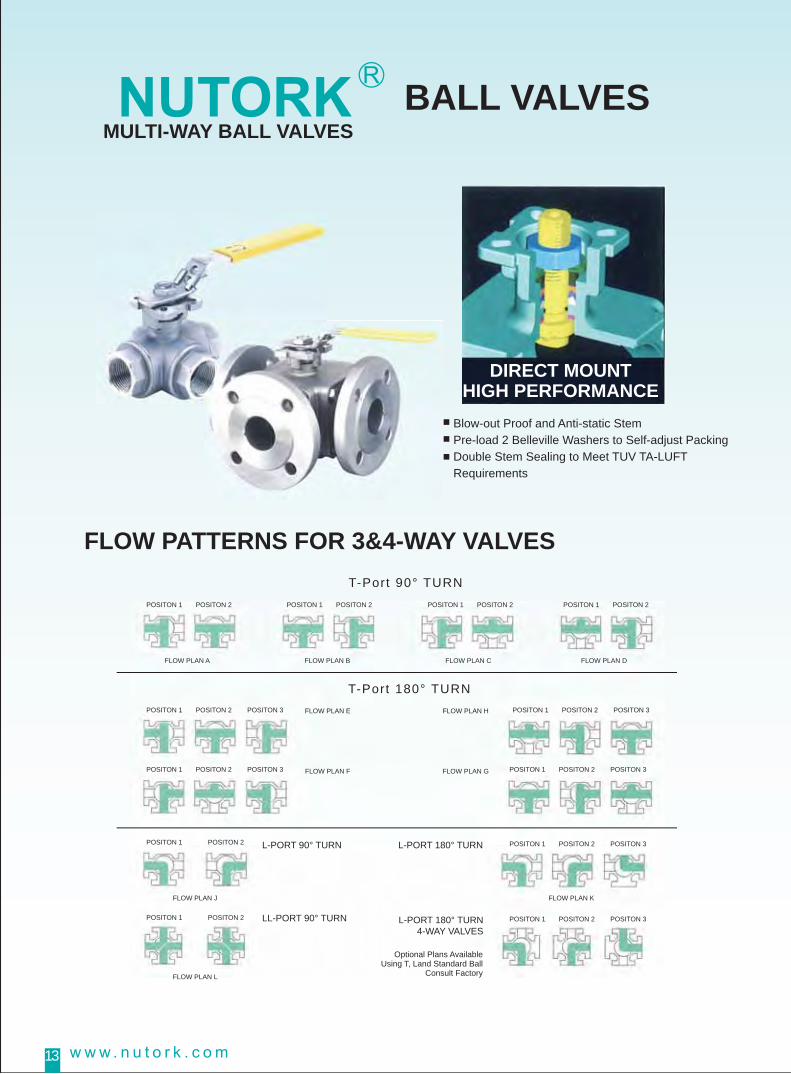
Blow-out Proof and Anti-static StemPre-load 2 Belleville Washers to Self-adjust PackingDouble Stem Sealing to Meet TUV TA-LUFT Requirements
T-Port 90° TURN
L-PORT 90° TURN L-PORT 180° TURN
L-PORT 180° TURN4-WAY VALVES
LL-PORT 90° TURN
T-Port 180° TURN
FLOW PATTERNS FOR 3&4-WAY VALVES
BALL VALVESMULTI-WAY BALL VALVES
DIRECT MOUNTHIGH PERFORMANCE
POSITON 1 POSITON 2
POSITON 1 POSITON 2 POSITON 3 POSITON 1 POSITON 2 POSITON 3FLOW PLAN E
FLOW PLAN F
FLOW PLAN H
FLOW PLAN GPOSITON 1 POSITON 2 POSITON 3 POSITON 1 POSITON 2 POSITON 3
POSITON 1 POSITON 2 POSITON 3
POSITON 1
Optional Plans AvailableUsing T, Land Standard Ball
Consult Factory
POSITON 2 POSITON 3
FLOW PLAN A
POSITON 1 POSITON 2
POSITON 1 POSITON 2
FLOW PLAN J FLOW PLAN K
FLOW PLAN L
POSITON 1 POSITON 2
FLOW PLAN B
POSITON 1 POSITON 2
FLOW PLAN C
POSITON 1 POSITON 2
FLOW PLAN D
14
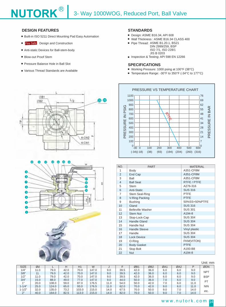
NO.123456789
10111213141516171819202122
PART MATERIALA351-CF8MA351-CF8MA351-CF8MRTFE / PTFEA276-316SUS 316PTFEPTFE50%SS+50%PTFESUS 316SUS 301A194-8SUS 304 SUS 304SUS 304Vinyl plasticSUS 304SUS 304FKM(VITON)PTFEA193-B8A194-8
BodyEnd CapBallBall SeatStemAnti-StaticStem Seal-RingV-Ring PackingBushing GlandBelleville WasherStem Nut Stop-Lock-CapHandle GlandHandle NutHandle SleeveHandleLock DeviceO-RingBody GasketStop Bolt Nut
Unit: mm
21
16151413121110
9
8
7
6
5
4
3
2
1
1718
1920
22
H42.042.042.049.059.065.073.282.5
L79.079.079.088.0108.0124.0135.0164.0
H170.070.070.077.087.093.0103.0113.0
W147.0147.0147.0147.0176.5176.5215.0215.0
J9.09.09.09.011.011.014.014.0
F39.539.539.544.054.062.067.582.0
P9.09.09.09.011.011.014.014.0
ØB142.042.042.050.050.070.070.070.0
ØB236.036.036.036.042.042.050.050.0
ØA16.06.06.07.07.09.09.09.0
ØA26.06.06.06.06.06.07.07.0
Ød11.011.
11.015.020.025.032.040.0
ØDN
NPT
BSP
PT
NIN
etc.
SIZE1/4”3/8”1/2”3/4”1”
1-1/4”1-1/2”
2”
PRESSURE VS TEMPERATURE CHART
PRES
SUR
E IN
PSI
G
PRES
SUR
E IN
BAR
11001000
900800700600500400300200100
0-30
(-34)(-18) (38) (93) (194) (204) (260) (316)0 100 200 300 400 500 600
7669625548413428211470
RTFE
3- Way 1000WOG, Reduced Port, Ball Valve
STANDARDS
SPECIFICATIONS
Design: ASME B16.34, API 608Wall Thickness : ASME B16.34 CLASS 400Pipe Thread:
Working Pressure: 1000 psing at 100°F (38°C)Temperature Range: -30°F to 350°F (-34°C to 177°C)
ASME B1.20.1, BS21DIN 2999/259, BSPISO 7/1, ISO 228/1JIS B 0203
Inspection & Testing: API 598 EN 12266
DESIGN FEATURESBuilt-in ISO 5211 Direct Mounting Pad Easy Automation
Design and Construction
Anti-static Devices for Ball-stem-body
Blow-out Proof Stem
Pressure Balance Hole in Ball Slot
Various Thread Standards are Available
Fire Safe

15
DN15~DN80
APPLICABLE STANDARDS :
SPECIFICATIONS :
Design Rating: DIN 3357/1,2, EN 12516-1End Flange: DIN 2542~DIN 2545,EN 1092Wall Thickness : ASME B16.34 , EN 12516-1Inspection & Testing: DIN 3203/3, EN 12266, API 598,API 6DConnection: DIN 2501/1 PN 10-40
Working Pressure: 40 Bar at 38°CTemperature Range: -30°F to 350°F(-34°C to 177°C)
DIN PN10/40 DIMENSION TABLE
NO.123456789101112131415
PART MATERIAL1.44081.44081.4408
PTFEFKM(VITON)PTFE50%SS+50%PTFESUS 316SUS 301A194-8SUS 304SUS 304SUS 304
1.43081.43081.4308PTFE
A193-B8 A193-B7
1.06191.0619
Body Cap BallBall SeatBolting Stem Seal-Ring O-Ring V-Ring Packing Bushing GlandBelleville Washer Stem NutStop-Lock-CapHandle GlandHandle (1/2-3”)
Unit: mm
9
10
1112
13 14 15 16 17
23 242928272625
18 19 20 21 22
8765
4
321
DN15DN20DN25DN32DN40DN50
ØD15.020.025.032.038.049.0
ØC45.058.068.078.088.0
102.0
Øh14.014.014.018.018.018.0
Øh16.016.016.016.016.019.019.019.019.0
ØA16.06.06.06.07.07.0
ØA26.07.07.09.09.09.0
ØB136.036.042.042.050.050.0
ØB242.050.050.070.070.070.0
ØE95.0
105.0115.0140.0150.0165.0
ØB65.075.085.0
100.0110.0125.0
ØB65.070.079.288.998.6
120.7139.7125.4190.5
F2.02.02.02.03.03.0
T16.018.018.018.018.020.018.022.020.024.020.024.0
H53.058.570.077.586.592.0
H183.088.5
104.0111.5120.5126.0
N4.04.04.04.04.04.04.08.0
N4.04.04.04.04.04.04.04.08.0
W144.5144.5175.0175.0200.0200.0
P9.09.011.011.014.014.0
M9.09.011.011.014.014.0
K7/16-20UNF7/16-20UNF9/16-18UNF9/16-18UNF9/4-18UNF9/4-18UNF
L150.0160.0180.0190.0212.0230.0
10/1625/4010/1625/4010/1625/40
310.0320.0350.0370.0
158.0162.0
220.0235.0
180.0190.0
1/2”3/4”1”
1-1/4”1-1/2”
2”
DN65
DN80
DN100
DN15DN20DN25DN32DN40DN50DN65DN80
DN100
2-1/2”
3”
4”
63.0
75.0
99.0
290.0 122.0
138.0
185.0
200.0
145.0
160.0
3.0
3.0
3.0
107.0
119.0
150.0
155.0
167.0
214.0
18.0
18.0
18.0
265.0
265.0
400.0
17.0
17.0
22.0
17.0
17.0
22.0
9.0
9.0
non
11.0
11.0
11.0
70.0
70.0
non
102.0
102.0
102.0
7/8-14UNF
7/8-14UNF
1-1/8-12UNF
8.0
8.0
10
16
25
40
SIZE PN
ASME CLASS 300 DIMENSION TABLE Unit: mm
ASME CLASS 150 DIMENSION TABLE Unit: mm
DESIGN FEATURESBuilt-in ISO 5211 Direct Mounting Pad Easy Automation. Design and ConstructionAnti-static Devices for Ball-stem-bodyBlow-out Proof StemPressure Balance Hole in Ball Slot
Fire Safe
3- Way DIN PN 10-40 / CLASS 150 / 300LB Full Port, Ball Valve
NO.1617181920212223242526272829
PART MATERIAL1.4408SUS 304PTFEVINYL PLASTIC1.4408
PVCA193-B8A194-81.4408A193-B8A53+Zn PlateVINYL PLASTICSUS 304
1.4308 1.0619
1.4308 1.0619A193-B8 A193-B7
End CapLock Device(1/2-3”)Body Gasket Handle Sleeve (1/2-3”)Seat RetainerBolt Flange CoverStop BoltNut Handle Adapter (4”)Set Screwed Handle (4”)Handle SleeveTriangie stopper (4”)
2292282272262255555555
9
10
1112
13 14 15 16 17 18 19 220 221 222
8765
4
321
UL
150.0160.0180.0190.0212.0235.0300.0330.0380.0
H183.088.5
104.0111.5120.5126.0155.0167.0214.0
H53.058.570.077.586.592.0
107.0119.0150.0
F1.61.61.61.61.61.61.61.61.6
T9.7
10.511.212.714.215.917.519.123.9
P9.09.011.011.014.014.017.017.022.0
W144.5144.5175.0175.0200.0200.0350.0350.0400.0
M9.09.011.011.014.014.017.017.022.0
ØA16.06.06.06.07.07.09.09.0--
ØB136.036.042.042.050.050.070.070.0
--
ØB242.050.050.070.070.070.0102.0102.0102.0
ØA26.07.07.09.09.09.011.011.011.0
ØD15.020.025.032.038.049.063.075.099.0
ØC35.043.051.063.573.292.0
104.7127.0157.2
ØE89.098.6
108.0117.0127.0152.2177.8190.5228.6
1/2”3/4”1”
1-1/4”1-1/2”
2”2-1/2”
3”4”
K7/16-24UNF7/16-24UNF9/16-18UNF9/16-18UNF3/4-18UNF3/4-18UNF7/8-14UNF7/8-14UNF
1-1/8-12UNF
SIZE Rating
AS
ME
CLA
SS
150
Øh16.016.016.016.016.019.022.322.322.3
ØB66.582.688.998.6114.3127.0149.4168.1200.2
N4.04.04.04.04.08.08.08.08.0
DN15DN20DN25DN32DN40DN50DN65DN80
DN100
L150.0160.0180.0195.0215.0235.0300.0330.0380.0
H183.088.5
104.0111.5120.5126.0155.0167.0214.0
H53.058.570.077.586.592.0
107.0119.0150.0
F1.61.61.61.61.61.61.61.61.6
T14.315.917.519.120.722.325.428.631.8
P9.09.011.011.014.014.017.017.022.0
W144.5144.5175.0175.0200.0200.0350.0350.0400.0
M9.09.011.011.014.014.017.017.022.0
ØA16.06.06.06.07.07.09.09.0--
ØB136.036.042.042.050.050.070.070.0
--
ØB242.050.050.070.070.070.0102.0102.0102.0
ØA26.07.07.09.09.09.011.011.011.0
ØD15.020.025.032.038.049.063.075.099.0
ØC35.043.051.063.573.292.0
104.7127.0157.2
ØE89.3117.4124.0133.4155.5165.1190.5209.6254.0
1/2”3/4”1”
1-1/4”1-1/2”
2”2-1/2”
3”4”
K7/16-24UNF7/16-24UNF9/16-18UNF9/16-18UNF3/4-18UNF3/4-18UNF7/8-14UNF7/8-14UNF
1-1/8-12UNF
SIZE Rating
AS
ME
CLA
SS
300
16
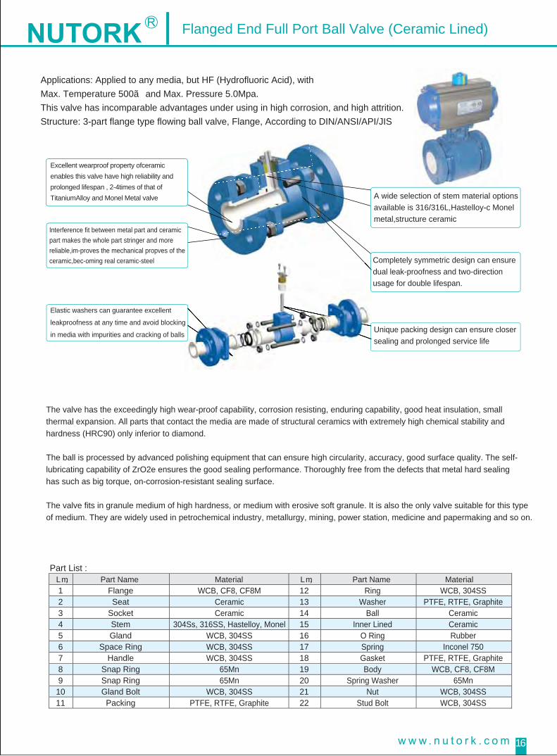
Flanged End Full Port Ball Valve (Ceramic Lined)
Applications: Applied to any media, but HF (Hydrofluoric Acid), with Max. Temperature 500℃ and Max. Pressure 5.0Mpa.This valve has incomparable advantages under using in high corrosion, and high attrition.Structure: 3-part flange type flowing ball valve, Flange, According to DIN/ANSI/API/JIS
The valve has the exceedingly high wear-proof capability, corrosion resisting, enduring capability, good heat insulation, small thermal expansion. All parts that contact the media are made of structural ceramics with extremely high chemical stability and hardness (HRC90) only inferior to diamond.
The ball is processed by advanced polishing equipment that can ensure high circularity, accuracy, good surface quality. The self-lubricating capability of ZrO2e ensures the good sealing performance. Thoroughly free from the defects that metal hard sealing has such as big torque, on-corrosion-resistant sealing surface.
The valve fits in granule medium of high hardness, or medium with erosive soft granule. It is also the only valve suitable for this type of medium. They are widely used in petrochemical industry, metallurgy, mining, power station, medicine and papermaking and so on.
Part List :No. Part Name Material No. Part Name Material 1234567891011
1213141516171819202122
FlangeSeat
SocketStemGland
Space RingHandle
Snap RingSnap RingGland BoltPacking
RingWasher
BallInner Lined
O RingSpringGasketBody
Spring WasherNut
Stud Bolt
WCB, CF8, CF8MCeramicCeramic
304Ss, 316SS, Hastelloy, MonelWCB, 304SSWCB, 304SSWCB, 304SS
65Mn65Mn
WCB, 304SSPTFE, RTFE, Graphite
WCB, 304SSPTFE, RTFE, Graphite
CeramicCeramicRubber
Inconel 750PTFE, RTFE, Graphite
WCB, CF8, CF8M65Mn
WCB, 304SSWCB, 304SS
Excellent wearproof property ofceramic enables this valve have high reliability and prolonged lifespan , 2-4times of that of TitaniumAlloy and Monel Metal valve
Interference fit between metal part and ceramic part makes the whole part stringer and more reliable,im-proves the mechanical propves of the ceramic,bec-oming real ceramic-steel
Elastic washers can guarantee excellent
leakproofness at any time and avoid blocking
in media with impurities and cracking of balls
A wide selection of stem material options available is 316/316L,Hastelloy-c Monel metal,structure ceramic
Completely symmetric design can ensure dual leak-proofness and two-direction usage for double lifespan.
Unique packing design can ensure closer sealing and prolonged service life

17
Flanged End Full Port Ball Valve (Ceramic Lined)
KgDIN P 16 Flange Dia.N ANSI CLASS 150 Flange Dia.DN Figure Size
108 45 65 95 4-M12 14 2 35 60.5 89 11 1.6117 55 75 105 14 2 43 70 98 11 1.6127 65 85 115 14 2 51 79.5 108 11 1.6140 78 100 135 16 2 64 89 117 13 1.6165 85 110 145 16 3 73 98.5 127 14 1.6178 100 125 160 16 3 92 120.5 152 16 1.6190 120 145 180 4-M16 18 3 105 139.5 178 18 1.6203 135 160 195 8-M16 20 3 127 152.5 190 19 1.6229 155 180 215 8-M16 20 3 157 190.5 229 24 1.6254 185 210 245 8-M16 22 3 186 216 254 24 1.6267 210 240 280 8-M20 24 3 216 241.5 279 25 1.6292 265 295 335 12-M20 26 3 270 298.5 343 29 1.6
4-M124-M124-M124-M124-M124-M164-M164-M168-M168-M208-M208-M20
8594
100114121140158176202252276293
160160230230320320
400320
2.93.44.36.89.3
12.614.922.330415476
L W HdnmmInch15 1520 1525
253232404050
65 5080 65
100 80125 100150 100200 150
D1 D2 D3 N-M T f D1 D2 D3 T f
20
N-M
4-M164-M164-M164-M124-M12
DIN P 40 Flange Dia.N ANSI CLASS 300 Flange Dia.DN KgFigure Size
45 65 95 4-M12 16 2 35 66.5 95 15 1.655 75 105 16 2 43 82.5 117 16 1.665 85 115 16 2 51 89 124 18 1.678 100 135 18 2 64 98.5 133 19 1.685 110 145 18 3 73 114.5 156 21 1.6
100 125 160 20 3 92 127 165 22 1.6120 145 180 8-M16 22 3 105 149.5 190 25 1.6135 160 195 8-M16 22 3 127 168 210 29 1.6160 190 230 8-M20 24 3 157 200.5 254 32 1.6188 220 270 28 3 186 235 279 35 1.6218 250 300 30 3 216 270.5 318 37 1.6282 320 375 38 3 270 330 381 41 1.6
4-M124-M164-M164-M164-M208-M168-M208-M20
8-M2012-M20
90100105120128146165185210265290308
3.54.15.28.2
11.315.117.926.836496593
160160230230320320
400320
108117127140165178190203229254267292
8-M248-M24
12-M27
8-M20
12-M24
L W H15 1520 1525
253232404050
65 5080 65
100 80125 100150 100200 150
D1 D2 D3 N-M T f D1 D2 D3 T f
20
N-M
4-M124-M164-M164-M164-M16
dnmmInch1/2”3/4”1”
1 1/4”1 1/2”
2”2 1/2”
3”4”5”6”8”
108 160 85 45 65 95 4-M12 16 2 52 70 95 4-M12 14 1117 94 55 75 105 16 2 58 75 100 4-M12 16 1127 100 65 85 115 16 2 70 90 125 4-M16 16 1140 114 78 100 135 18 2 80 100 135 4-M16 18 2165 121 85 110 145 18 3 85 105 140 4-M16 18 2178 140 100 125 160 20 3 100 120 155 8-M16 18 2190 158 120 145 180 8-M16 22 3 120 140
2008-M16 20 2
203 176 135 160 195 8-M16 22 3 135 160225
8-M20 22 2229 202 160 190 230 8-M20 24 3 160 185
2708-M20 24 2
254 252 188 220 270 28 3 195 225305
8-M24 26 2267 276 218 250 300 30 3 230 260
35028 2
292 293 278 310 360 34 3 275 03503 2
160230230320320
400320 175
8-M248-M24
12-M2412-M2412-M24
2.93.44.36.89.3
12.614.922.330415476
L W HdnmmInch15 1520 1525
253232404050
65 5080 65
100 80125 100150 100200 150
D1 D2 D3 N-M T f D1 D2 D3 T f
20
N-M
4-M124-M164-M164-M164-M16
DIN PN25 Flange Dia. JIS 20K Flange Dia.DN KgFigure Size
KgL W HdnmmInch
15 15 108 160 85 45 65 95 4-M12 14 2 52 70 95 4-M12 12 1 2.920 15 117 94 55 75 105 14 2 58 75 100 4-M12 14 1 3.425
25127 100 65 85 115 14 2 70 90 125 4-M16 14 1 4.3
3232
140 114 78 100 135 16 2 80 100 135 4-M16 16 2 6.840
40165 121 85 110 145 16 2 85 105 140 4-M16 16 2 9.3
50 178 140 100 125 160 16 3 100 120 155 4-M16 16 2 12.665 50 190 158 120 145 180 4-M16 18 3 120 140
1854-M16 18 2 14.9
80 65 203 176 135 160 195 8-M16 20 3 130 150210
8-M16 18 2 22.3100 80 229 202 155 180 215 8-M16 20 3 155 175
2508-M16 18 2 30
125 100 254 252 185 210 245 22 3 185 210280
8-M20 20 2 41150 100 267 276 210 240 280 24 3 215 240
3308-M20 22 2 54
200 150 292 293 265 295 335 26 3 265 290 12-M20 22 2 76
D1 D2 D3 N-M T f D1 D2 D3 N-M T f
160230230320320
400320 173
8-M168-M20
12-M20
20
4-M164-M164-M164-M124-M12
DIN PN10 Flange Dia. JIS 10K Flange Dia.DN Figure Size
Remarks:ceramicballvalvewithnominaldiameterlargerthanDN100allmatchedwithwormwheelmanualoperation
f N-M
DN D2D1 D3
W
T
H
L
dn NUTORK
NUTORK
PN10 / JIS10K :
PN16 / ANSI150LB :
PN25 / JIS20K :
PN40 / ANIS300LB :
1/2”3/4”1”
1 1/4”1 1/2”
2”2 1/2”
3”4”5”6”8”
1/2”3/4”1”
1 1/4”1 1/2”
2”2 1/2”
3”4”5”6”8”
1/2”3/4”1”
1 1/4”1 1/2”
2”2 1/2”
3”4”5”6”8”

PN10 / JIS10K :
PN16 / ANSI150LB :
PN25 / JIS20K :
PN40 / ANIS300LB :
18
Flanged End Full Port Ball Valve (Ceramic Lined)
W Hmm15 160 84 45 65 95 4- 14Φ 16 2 52 95 4- 15Φ 14 120 160 84 55 75 105 16 2 58 100 4- 15Φ 16 125 230 95 65 85 115 16 2 70 125 4- 19Φ 16 132 230 95 78 100 135 18 2 80 135 4- 19Φ 18 240 320 138 85 110 145 18 3 85 140 4- 19Φ 18 250 320 147 100 125 160 20 3 100 155 4- 19Φ 18 265 400 185 120 145 180 4- 18Φ 22 3 120 175 8- 19Φ 20 280 400 194 135 160 195 8- 18Φ 22 3 135 200 8- 23Φ 22 2
100 700 210 160 190 230 8- 23Φ 24 3 160 225 8- 23Φ 24 2125 700 265 188 220 270 8- 25Φ 28 3 195 270 8- 25Φ 26 2150 1100 290 218 250 300 8- 25Φ 30 3 230 305 12- 25Φ 28 2200 1100 308 278 310 360 12- 25Φ 34 3 275 350 12- 25Φ 30 2
D1 D2 D3 T f D1 D3 T fL130130140165165203222241305381403419
707590
100105120140160185225260305
D2HL66699197
123130143176192230252278
108117129140165180190200235300340350
4- 14Φ4- 14Φ4- 18Φ4- 18Φ4- 18Φ
Inch N- dΦ N- dΦN- dΦ
W Hmm15 160 67 45 65 95 4- 14Φ 16 2 35 4- 15Φ 1520 160 70 55 75 105 16 2 43 4- 19Φ 1625 230 89 65 85 115 16 2 811532 230 95 78 100 135 18 2 64 1940 320 122 85 110 145 18 2 73 2150 320 130 100 125 160 20 3 92 8- 19Φ 2265 400 157 120 145 180 4- 18Φ 22 3 105 8- 22Φ 2580 400 186 135 160 195 4- 18Φ 22 3 127 8- 22Φ 29
100 700 203 160 190 230 8- 23Φ 24 3 157 8- 22Φ 32125 700 252 188 220 270 8- 25Φ 28 3 186 8- 22Φ 35150 1100 276 218 250 300 8- 25Φ 30 3 216 12- 22Φ 37200 1100 293 282 320 375 12- 30Φ 38 3 270 41
D1 D2 D3 T f D1 T fL140152165180200230290310350356394457
95117124133156165190210254279318381
D3HL66699197
123130143176192230252278
108117127140165178190203229350414439
66.582.589
98.5114.5127
149.5168
200.5235
270.5330
D2
4- 19Φ4- 19Φ4- 22Φ
12- 25Φ
1.61.61.61.61.61.61.61.61.61.61.61.6
4- 14Φ4- 14Φ4- 18Φ4- 18Φ4- 18Φ
Inch N- dΦN- dΦ
W HmmInch15 130 84 45 65 95 4- 14Φ 14 2 35 4- 15Φ 1120 130 84 55 75 105 14 2 43 4- 15Φ 1125 160 95 65 85 115 14 2 51 1132 160 95 78 100 135 16 2 64 1340 250 138 85 110 145 16 2 73 1450 250 147 100 125 160 16 3 92 4- 19Φ 1665 400 185 120 145 180 4- 18Φ 18 3 105 4- 19Φ 1880 400 194 135 160 195 4- 18Φ 20 3 127 8- 19Φ 19
100 700 210 155 180 215 8- 18Φ 20 3 157 8- 19Φ 24125 700 265 185 210 245 8- 18Φ 22 3 186 8- 22Φ 24150 1100 290 210 240 280 8- 23Φ 24 3 216 8- 22Φ 25200 1100 308 265 295 335 12- 23Φ 26 3 270 29
D1 D2 D3 T f D1 T fL130130140165165203222241305381403419
8998108117127152178190229254279343
D3HL66699197
123130143176192230252278
108117127140165178190203229356394457
60.570
79.589
98.5120.5139.5152.5190.5216
241.5298.5
D2
4- 15Φ4- 15Φ4- 15Φ
8- 22Φ
1.61.61.61.61.61.61.61.61.61.61.61.6
4- 14Φ4- 14Φ
4- 18Φ4- 18Φ
4- 18Φ
N- d d-NΦ Φ
W Hmm15 130 84 45 65 95 4- 14Φ 14 2 52 95 4- 15Φ 12 120 130 84 55 75 105 14 2 58 100 4- 15Φ 14 125 160 95 65 85 115 14 2 70 125 4- 19Φ 14 132 160 95 78 100 135 16 2 80 135 4- 19Φ 16 240 250 138 85 110 145 16 2 85 140 4- 19Φ 16 250 250 147 100 125 160 16 3 100 155 4- 19Φ 16 265 400 185 120 145 180 4- 18Φ 18 3 120 173 4- 19Φ 18 280 400 194 135 160 195 4- 18Φ 20 3 130 185 8- 19Φ 18 2
100 700 210 155 180 215 8- 18Φ 20 3 155 210 8- 19Φ 18 2125 700 265 185 210 245 8- 18Φ 22 3 185 250 8- 3Φ2 20 2150 1100 290 210 240 280 8- 23Φ 24 3 215 280 8- 23Φ 22 2200 1100 308 265 295 335 12- 23Φ 26 3 265 330 12- 23Φ 22 2
D1 D2 D3 T f D1 D3 T fL130130140165165203222241305381403419
707590
100105120140150175210240290
D2HL66698697
123130148174190230252278
108117129140165180190200235300340350
4- 14Φ4- 14Φ
4- 18Φ4- 18Φ4- 18Φ
Inch N- dΦ N- dΦ
DIN PN40 Figure Size & Flange Dia. ANSI CLASS 300 Figure Size & Flange Dia.DN
.aiDegnalF&eziSerugiFK02SIJ.aiDegnalF&eziSerugiF52NPNIDDN
DIN PN16 Figure Size & Flange Dia. ANSI CLASS 150 Figure Size & Flange Dia.DN
.aiDegnalF&eziSerugiFK01SIJ.aiDegnalF&eziSerugiF01NPNIDDN
N-ΦdN-M
DDN
D2
D1
D3
H
L
W
fT
1/2”3/4”1”
1 1/4”1 1/2”
2”2 1/2”
3”4”5”6”8”
1/2”3/4”1”
1 1/4”1 1/2”
2”2 1/2”
3”4”5”6”8”
1/2”3/4”1”
1 1/4”1 1/2”
2”2 1/2”
3”4”5”6”8”
1/2”3/4”1”
1 1/4”1 1/2”
2”2 1/2”
3”4”5”6”8”
Agent:NUTORK Corp.No.10, Lane 899, Zhuguang Road, Qingpu Area, Shanghai, ChinaTel:+86-21-5988-7103/ 5988-8463 +86-21-5988-8436Fax:+86-21-5988-7203E-mail:[email protected]: www.nutork.com
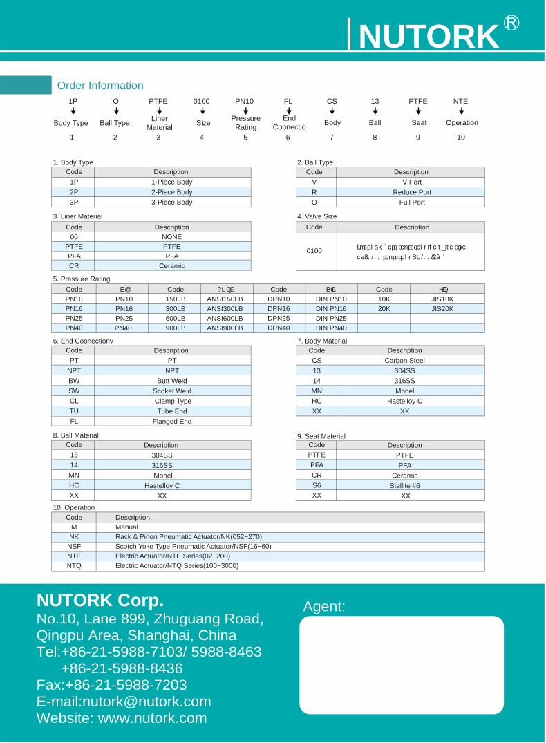
NUTORK Order Information
1. Body Type 2. Ball Type
3. Liner Material
5. Pressure Rating
6. End Coonectionv
8. Ball Material
10. Operation
9. Seat Material
7. Body Material
4. Valve Size
1P
Body Type
Code1P2P3P
Description 1-Piece Body2-Piece Body3-Piece Body
Code00
PTFEPFACR
DescriptionNONEPTFEPFA
Ceramic
CodePN10PN16PN25PN40
CodeDPN10DPN16DPN25DPN40
CodePT
NPTBWSWCLTUFL
Code1314MNHCXX
CodeMNK
NSFNTENTQ
DescriptionManual Rack & Pinon Pneumatic Actuator/NK(052~270)Scotch Yoke Type Pneumatic Actuator/NSF(16~60)Electric Actuator/NTE Series(02~200)Electric Actuator/NTQ Series(100~3000)
Description 304SS316SS Monel
Hastelloy CXX
CodePTFEPFACRS6XX
DescriptionPTFEPFA
CeramicStellite #6
XX
CodeCS1314MNHCXX
DescriptionCarbon Steel
304SS316SSMonel
Hastelloy CXX
Description PT
NPTButt Weld
Scoket Weld Clamp Type
Tube EndFlanged End
GBPN10PN16PN25PN40
Code150LB300LB600LB900LB
ANSI ANSI150LBANSI300LBANSI600LBANSI900LB
DINDIN PN10DIN PN16DIN PN25DIN PN40
Code10K20K
JISJIS10KJIS20K
CodeVRO
Description V Port
Reduce PortFull Port
Code Description
1 2 3 4 5 6 7 8 9 10
Ball Type LinerMaterial Size Pressure
RatingEnd
Coonectio Body Ball Seat Operation
O PTFE NTEPTFE0100 PN10 FL CS 13
0100 Four numbers represent the valve size.
eg: 0100 represent DN100(4″)