5 ton convertible dual fuel packaged units 4dcz6060a3120a · 5 ton convertible dual fuel packaged...
TRANSCRIPT

© 2007 American Standard Inc. All Rights Reserved
5 Ton Convertible Dual Fuel Packaged Units4DCZ6060A3120A
TAG: _________________________________ SUBMITTAL
4DCZ6060-SUB-3
PRODUCT SPECIFICATIONS
11111 Certified in accordance with the Unitary Air-Conditioner Equipmentcertification program, which is based on ARI Standard 210/240. Noisecalculated in accordance with A.R.I. Standard 270.
22222 All models are U L Listed. Ratings shown are for elevations up to 2000ft. For higher elevations reduce ratings at a rate of 4% per 1000 ft.elevation.
33333 Convertible to LPG.
44444 This value is approximate. For more precise value, see Unit Nameplate.
55555 Based on U.S. Government Standard Tests.
66666 Filters must be installed in return air stream. Square footages listed arebased on 300 f.p.m. face velocity. If permanent filters are used size permanufacturer's recommendation with a clean resistance of 0.05" W.C.
MODELRATED Volts/PH/HzPerformance Cooling BTUH�BTUH (High)Indoor Airflow (CFM)Power Input (KW)BTUH (Low)Indoor Airflow (CFM)Power Input (KW)EER - HI / LOW / SEERSound Rating No.�HP Heating Performance�(High Temp.)BTUH / COP (High)Power Input (KW)(Low Temp.) BTUH / COP (High)Power Input (KW)(High Temp.)BTUH / COP (Low)Power Input (KW)(Low Temp.) BTUH / COP (Low)Power Input (KW)HSPF (BTU / Watt-Hr.)�Gas Heating Performance�Input BTUH - 1st Stage (Natural Gas)Input BTUH - 2nd Stage (Natural Gas)AFUETemp. Rise — Min/Max (°F)Orifice Qty / Drill Size (Natural Gas)�POWER CONN.—V/PH/HZMin. Brch. Cir. Ampacity�Fuse Size — Max. / Recmd. (amps)COMPRESSORVolts/Ph/HzR.L. Amps — L.R. AmpsOUTDOOR COIL — TYPERows/F.P.I.Face Area (sq.ft.)Tube Size (in.)INDOOR COIL — TYPERows/F.P.I.Face Area (sq.ft.)Tube Size (in.)Refrigerant ControlDrain Conn. Size (in.)OUTDOOR FAN — TYPEDia. (in.)Drive/No. SpeedsMotor — HP/R.P.M.Volts/Ph/HzF.L. Amps/L.R. AmpsINDOOR FAN — TYPEDia x Width (in.)Drive/No. SpeedsCFM @ 0.0 in. w.g.�Motor — HP/R.P.M.Volts/Ph/HzF.L. Amps/L.R. AmpsCOMBUSTION FAN — TYPEDrive/No. SpeedsMotor — HP/R.P.M.Volts/Ph/HzFLAFILTER / FURNISHEDType RecommendedRecmd. Face Area (sq. ft.)�REFRIGERANT / Charge (lbs.)GAS PIPE SIZE (in.)DIMENSIONSCrated (in.)WEIGHT / Shipping / Net (lbs.)
4DCZ6060A3120A208-230/3/60
5700019004.38
4050013503.26
11.5 / 12.5 / 15.273
55000 / 3.84.38
34500 / 2.524
39000 / 3.633.14
23000 / 2.213.038.6
90000120000
8030 / 603 / #32
208-230/3/6030.3
45 / 452-STAGE SCROLL
208-230/3/6017.6 / 123SPINE-FIN
2 / 2423.573/8
PLATE FIN4 / 1523.573/8
EXPANSION VALVE3/4 FEMALE NPT
PROPELLER28.21 / 1
1/4 / 830208-230/1/60
1.4 / 3.4CENTRIFUGAL
11 X 10DIRECT / VARIABLE
SEE FAN PERFORMANCE TABLE1 / VARIABLE208-230/1/60
6.9 / 6.9CENTRIFUGAL
DIRECT / 21/45 / 2800/1500
208-230/1/600.34NO
THROWAWAY6.7
R410A / 9.41/2
H X W X L51.86 / 47.4 / 61.75
676 / 548

2© 2007 American Standard Inc. All Rights Reserved
Dimensional Data
4DCZ6048A through 4DCZ6060A (1 of 3)

3
Dimensional Data
4DCZ6048A through 4DCZ6060A (2 of 3)

4© 2007 American Standard Inc. All Rights Reserved
Dimensional Data
4DCZ6048A through 4DCZ6060A (3 of 3)

5
Performance DataHIGH STAGE: 4DCZ6048A AT 1600 NOM CFM (COOLING PERFORMANCE AT INDOOR DRY BULB TEMPERATURES)
OD ID TOT SENS CAP AT ENTERING DB TEMP TOTALAMB WB CAP 72 75 78 80 KW
85
59 45.3 38.7 43.6 45.3 45.3 3.663 47.3 31.3 36.2 41.1 44.4 3.667 50.9 24.5 29.4 34.3 37.6 3.671 55.0 17.6 22.5 27.4 30.8 3.6
95
59 42.3 37.4 42.3 42.3 42.3 3.963 44.2 30.0 34.9 39.8 43.1 3.967 47.6 23.2 28.1 33.0 36.3 4.071 51.4 16.3 21.3 26.2 29.5 4.0
105
59 39.4 36.0 39.4 39.4 39.4 4.263 41.0 28.7 33.7 38.6 41.0 4.267 44.2 21.9 26.9 31.8 35.1 4.371 47.8 15.1 20.0 25.0 28.3 4.3
115
59 36.4 34.7 36.4 36.4 36.4 4.563 37.9 27.5 32.4 37.3 37.9 4.567 40.9 20.7 25.6 30.6 33.9 4.671 44.1 13.9 18.8 23.8 27.1 4.6
USE THE FOLLOWING FACTORS TO COMPENSATE FOR DIFFERENT AIR FLOWAIR FLOW CAPACITY TOTAL POWERRATE, CFM MULTIPLIER MULTIPLIER
LOW 1400 0.97 0.98HIGH 1800 1.03 1.02
ARI RATING FOR COOLINGCFM CAPACITY (A) TEST SEER EER1585 47500 16.00 12.00
ARI Standard Capacity Rating ConditionsARI STANDARD 210/240 RATING CONDITIONS — (A) Cooling 80°F DB, 67°FWB air entering indoor coil, 95°F DB air entering outdoor coil. (B) HighTemperature Heating 47°F DB, 43°F WB air entering outdoor coil, 70°F DB airentering indoor coil. (C) Low Temperature Heating 17°F DB, 15°F WB air enteringoutdoor coil, 70°F DB air entering indoor coil. (D) Rated indoor airflow for heatingis the same as for cooling.
LOW STAGE: 4DCZ6048A AT 1200 NOM CFM (COOLING PERFORMANCE AT INDOOR DRY BULB TEMPERATURES)OD ID TOT SENS CAP AT ENTERING DB TEMP TOTAL
AMB WB CAP 72 75 78 80 KW
75
59 34.4 29.2 32.9 34.4 34.4 1.963 35.9 23.7 27.4 31.0 33.4 1.967 38.7 18.7 22.4 26.0 28.4 1.971 41.8 13.7 17.3 20.9 23.4 1.9
85
59 32.2 28.2 31.9 32.2 32.2 2.163 33.5 22.7 26.4 30.1 32.5 2.267 36.1 17.7 21.4 25.0 27.4 2.271 39.0 12.7 16.3 20.0 22.4 2.2
90
59 31.0 27.7 31.0 31.0 31.0 2.363 32.3 22.3 25.9 29.6 32.0 2.367 34.8 17.3 20.9 24.6 27.0 2.371 37.6 12.2 15.9 19.5 21.9 2.3
95
59 29.9 27.2 29.9 29.9 29.9 2.463 31.2 21.8 25.4 29.1 31.2 2.467 33.6 16.8 20.4 24.1 26.5 2.571 36.2 11.8 15.4 19.1 21.5 2.5
USE THE FOLLOWING FACTORS TO COMPENSATE FOR DIFFERENT AIR FLOWAIR FLOW CAPACITY TOTAL POWERRATE, CFM MULTIPLIER MULTIPLIER
LOW 1050 0.97 0.98HIGH 1350 1.03 1.02
ARI RATING FOR COOLINGCFM CAPACITY (A) TEST SEER EER1165 35107 16.00 13.58
ARI Standard Capacity Rating ConditionsARI STANDARD 210/240 RATING CONDITIONS — (A) Cooling 80°F DB, 67°FWB air entering indoor coil, 95°F DB air entering outdoor coil. (B) HighTemperature Heating 47°F DB, 43°F WB air entering outdoor coil, 70°F DB airentering indoor coil. (C) Low Temperature Heating 17°F DB, 15°F WB air enteringoutdoor coil, 70°F DB air entering indoor coil. (D) Rated indoor airflow for heatingis the same as for cooling.
HIGH STAGE: 4DCZ6048A AT 1600 NOM CFM (HEATING PERFORMANCE AT INDOOR DRY BULB TEMPERATURE)OD TOTAL CAPACITY MBH TOTAL POWER IN KILOWATTS
AMB 60 70 75 80 60 70 75 80
2 18.6 18.3 18.1 17.9 2.5 2.7 2.8 2.87 21.6 21.2 21.0 20.8 2.6 2.7 2.8 2.9
12 24.6 24.1 23.9 23.7 2.6 2.8 2.9 3.017 27.6 27.1 26.8 26.5 2.7 2.9 3.0 3.022 28.4 27.9 27.6 27.3 2.7 2.9 3.0 3.127 29.2 28.7 28.4 28.1 2.7 2.9 3.0 3.132 30.1 29.5 29.2 28.9 2.8 2.9 3.0 3.137 33.0 32.4 32.1 31.8 2.8 3.0 3.1 3.242 39.2 38.5 38.1 37.8 2.9 3.1 3.2 3.347 45.4 44.6 44.1 43.7 3.1 3.3 3.4 3.552 48.4 47.5 47.0 46.6 3.1 3.3 3.4 3.557 51.4 50.4 49.9 49.5 3.2 3.4 3.5 3.662 54.4 53.3 52.8 52.3 3.3 3.5 3.6 3.767 57.3 56.3 55.7 55.2 3.3 3.5 3.6 3.772 60.3 59.2 58.6 58.1 3.4 3.6 3.7 3.8
USE THE FOLLOWING FACTORS TO COMPENSATE FOR DIFFERENT AIR FLOWAIR FLOW CAPACITY TOTAL POWERRATE, CFM MULTIPLIER MULTIPLIER
LOW 1400 0.987 0.975HIGH 1800 1.011 1.025
ARI RATING FOR HEATINGCFM CAPACITY 47 COP 47 CAPACITY 17 COP 17 HSPF1585 44500 4.00 27000 2.76 9.00
ARI Standard Capacity Rating ConditionsARI STANDARD 210/240 RATING CONDITIONS — (A) Cooling 80°F DB, 67°F WB airentering indoor coil, 95°F DB air entering outdoor coil. (B) High Temperature Heating47°F DB, 43°F WB air entering outdoor coil, 70°F DB air entering indoor coil. (C) LowTemperature Heating 17°F DB, 15°F WB air entering outdoor coil, 70°F DB airentering indoor coil. (D) Rated indoor airflow for heating is the same as for cooling.
LOW STAGE: 4DCZ6048A AT 1200 NOM CFM (HEATING PERFORMANCE AT INDOOR DRY BULB TEMPERATURE)OD TOTAL CAPACITY MBH TOTAL POWER IN KILOWATTS
AMB 60 70 75 80 60 70 75 80
22 20.6 20.2 20.0 19.8 2.1 2.3 2.3 2.4
27 22.3 21.9 21.7 21.5 2.2 2.3 2.4 2.4
32 24.0 23.6 23.3 23.1 2.2 2.3 2.4 2.5
37 26.3 25.8 25.6 25.3 2.2 2.4 2.4 2.5
42 29.4 28.9 28.6 28.3 2.2 2.4 2.4 2.5
47 32.6 32.0 31.7 31.4 2.2 2.4 2.4 2.5
52 34.9 34.2 33.9 33.6 2.2 2.4 2.4 2.5
57 37.1 36.5 36.1 35.8 2.3 2.4 2.5 2.5
62 39.4 38.7 38.3 38.0 2.3 2.4 2.5 2.6
67 41.7 40.9 40.5 40.2 2.3 2.4 2.5 2.6
72 44.0 43.2 42.7 42.4 2.3 2.5 2.5 2.6
USE THE FOLLOWING FACTORS TO COMPENSATE FOR DIFFERENT AIR FLOWAIR FLOW CAPACITY TOTAL POWERRATE, CFM MULTIPLIER MULTIPLIER
LOW 1050 0.987 0.975HIGH 1350 1.011 1.025
ARI RATING FOR HEATINGCFM CAPACITY 47 COP 47 CAPACITY 17 COP 17 HSPF1165 31799 3.98 18430 2.44 9.00
ARI Standard Capacity Rating ConditionsARI STANDARD 210/240 RATING CONDITIONS — (A) Cooling 80°F DB, 67°F WB airentering indoor coil, 95°F DB air entering outdoor coil. (B) High Temperature Heating47°F DB, 43°F WB air entering outdoor coil, 70°F DB air entering indoor coil. (C) LowTemperature Heating 17°F DB, 15°F WB air entering outdoor coil, 70°F DB air enteringindoor coil. (D) Rated indoor airflow for heating is the same as for cooling.
6© 2007 American Standard Inc. All Rights Reserved
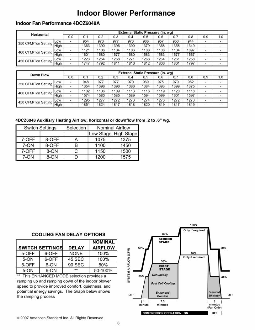
5-OFF 6-OFF NONE 100%
5-ON 6-OFF 45 SEC 100%
5-OFF 6-ON 90 SEC 50%
5-ON 6-ON ** 50-100%** This ENHANCED MODE selection provides a
ramping up and ramping down of the indoor blower
speed to provide improved comfort, quietness, and
potential energy savings. The Graph below shows
the ramping process
COOLING FAN DELAY OPTIONS
SWITCH SETTINGS DELAY
NOMINAL
AIRFLOW
OFF OFF
35%
56%
35% Dehumidify
Fast Coil Cooling
EnhancedEfficiency
7.5minutes
3minutes
(Fan Only)
1minute
SY
ST
EM
AIR
FL
OW
(C
FM
) 50%
80%
50%
100%
Only if required
SECOND STAGE
FIRST STAGE
70% Only if required
EnhancedComfort
COMPRESSOR OPERATION ON OFF
Indoor Blower PerformanceIndoor Fan Performance 4DCZ6048A
0.0 0.1 0.2 0.3 0.4 0.5 0.6 0.7 0.8 0.9 1.0Low - 954 973 977 973 966 957 950 944 - -High - 1363 1390 1396 1390 1379 1368 1358 1349 - -Low - 1121 1106 1104 1106 1108 1108 1104 1097 - -High - 1601 1580 1577 1580 1583 1583 1577 1567 - -Low - 1223 1254 1268 1271 1268 1264 1261 1258 - -High - 1747 1792 1811 1816 1812 1806 1801 1797 - -
0.0 0.1 0.2 0.3 0.4 0.5 0.6 0.7 0.8 0.9 1.0Low - 948 977 977 970 969 975 979 962 - -High - 1354 1396 1396 1386 1384 1393 1399 1375 - -Low - 1102 1106 1109 1113 1116 1119 1120 1118 - -High - 1574 1580 1585 1589 1594 1599 1601 1597 - -Low - 1295 1277 1272 1273 1274 1273 1272 1273 - -High - 1851 1824 1817 1818 1820 1819 1817 1819 - -
350 CFM/Ton Setting
400 CFM/Ton Setting
450 CFM/Ton Setting
External Static Pressure (in. wg)
External Static Pressure (in. wg)
Horizontal
Down Flow
350 CFM/Ton Setting
400 CFM/Ton Setting
450 CFM/Ton Setting
SelectionLow Stage High Stage
7-OFF 8-OFF A 1075 13757-ON 8-OFF B 1100 14507-OFF 8-ON C 1150 15007-ON 8-ON D 1200 1575
Switch Settings Nominal Airflow
4DCZ6048 Auxiliary Heating Airflow, horizontal or downflow from .2 to .6” wg.
7
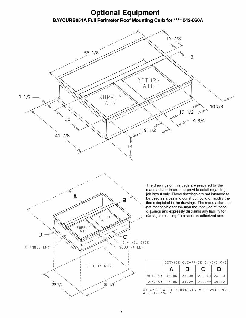
56 1/8
15 7/8
3
10 7/819 1/2
4 3/4
19 1/2
14
41 7/8
20
1 1/2
38 7/8 53 1/8
Optional Equipment
The drawings on this page are prepared by themanufacturer in order to provide detail regardingjob layout only. These drawings are not intended tobe used as a basis to construct, build or modify theitems depicted in the drawings. The manufacturer isnot responsible for the unauthorized use of thesedrawings and expressly disclaims any liability fordamages resulting from such unauthorized use.
BAYCURB051A Full Perimeter Roof Mounting Curb for *****042-060A

8© 2007 American Standard Inc. All Rights Reserved
Filter
BAYFLTR101, 201A, 1" - 2" Filter Rack(Mounts in Filter/Coil Section)
Optional Equipment
The drawings on this page are prepared by the manufacturer in order to provide detail regarding job layout only. These drawingsare not intended to be used as a basis to construct, build or modify the items depicted in the drawings. The manufacturer is notresponsible for the unauthorized use of these drawings and expressly disclaims any liability for damages resulting from suchunauthorized use.
9
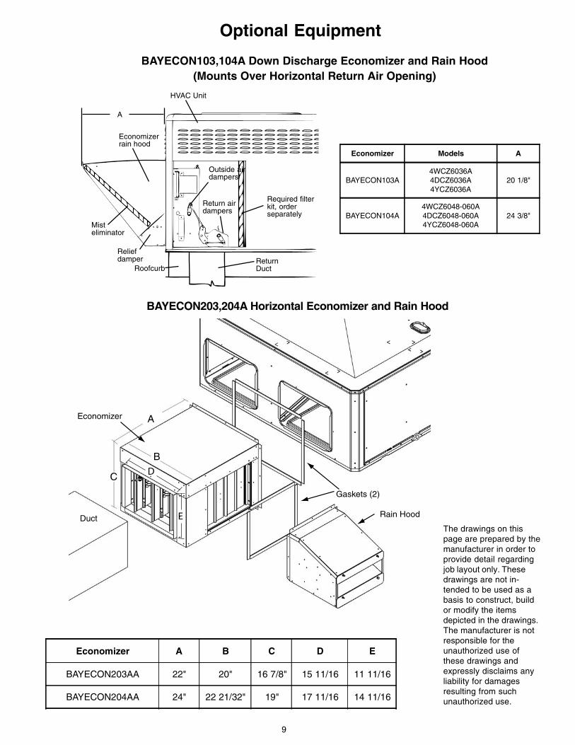
BAYECON103,104A Down Discharge Economizer and Rain Hood(Mounts Over Horizontal Return Air Opening)
A
B
C
Economizer
Gaskets (2)
Rain HoodDuct
D
E
BAYECON203,204A Horizontal Economizer and Rain Hood
ReturnDuctRoofcurb
Reliefdamper
Misteliminator
Economizerrain hood
HVAC Unit
Outside airdampers
Return airdampers
Required filterkit, orderseparately
A
Optional Equipment
The drawings on thispage are prepared by themanufacturer in order toprovide detail regardingjob layout only. Thesedrawings are not in-tended to be used as abasis to construct, buildor modify the itemsdepicted in the drawings.The manufacturer is notresponsible for theunauthorized use ofthese drawings andexpressly disclaims anyliability for damagesresulting from suchunauthorized use.
Economizer Models A
BAYECON103A4WCZ6036A4DCZ6036A4YCZ6036A
20 1/8"
BAYECON104A4WCZ6048-060A4DCZ6048-060A4YCZ6048-060A
24 3/8"
Economizer A B C D E
BAYECON203AA 22" 20" 16 7/8" 15 11/16 11 11/16
BAYECON204AA 24" 22 21/32" 19" 17 11/16 14 11/16
10© 2007 American Standard Inc. All Rights Reserved
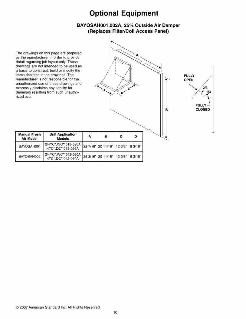
A
B
CD
FULLYOPEN
2/31/3
FULLYCLOSED
BAYOSAH001,002A, 25% Outside Air Damper(Replaces Filter/Coil Access Panel)
Optional Equipment
The drawings on this page are preparedby the manufacturer in order to providedetail regarding job layout only. Thesedrawings are not intended to be used asa basis to construct, build or modify theitems depicted in the drawings. Themanufacturer is not responsible for theunauthorized use of these drawings andexpressly disclaims any liability fordamages resulting from such unautho-rized use.
Manual FreshAir Model
Unit ApplicationModels
A B C D
BAYOSAH0012/4YC*,WC**018-036A4TC*,DC**018-036A
22 7/16" 20 11/16" 12 3/8" 9 3/16"
BAYOSAH0022/4YC*,WC**042-060A4TC*,DC**042-060A
25 3/16" 20 11/16" 12 3/8" 9 3/16"
11
Mechanical SpecificationsGeneral
All units shall be factory assembled, piped,internally wired and fully charged withrefrigerant. All units shall be designed tooperate at outdoor ambient temperaturesas high as 115°F. Cooling capacities shallbe rated in accordance with A.R.I.standards. The 4DCZ6 heating/cooling unitdesign is UL listed, specifically for outdoorapplications using natural gas or propane.All units shall be designed for outdoorrooftop or ground level installation. Unitcasing is constructed of heavy gauge,galvanized steel and painted with aweather-resistant powder paint.
Shipped for horizontal application,convertible to downflow.
Casings
All panels shall be heavy gauge steel,gasketed and insulated. Foil-facedinsulation shall be in the heat exchangersection. Foil-faced insulation shall be in theevaporator section. Base pan shall beheavy gauge steel. WEATHERGUARD™exterior corrosion resistant screws shall beused for added resistance to rust andcorrosion.
Controls
Refrigeration cycle controls shall includecondenser fan, evaporator fan andcompressor contactors. Compressors shallbe equipped with a combination internalwinding thermostat/current overload.Internal high pressure relief shall also beprovided.
Refrigeration System
Compressors —
The Climatuff® compressor featuresinternal over temperature and pressureprotector, total dipped hermetic motor.Other features include: roto lock suctionand discharge refrigeration connections,centrifugal oil pump, and low vibration andnoise.
Evaporator Coil — Internally enhanced3/8-inch OD seamless copper tubingmechanically bonded to aluminum fins,factory pressure and leak tested at 250 to300 psig. All units have TXV to controlrefrigeration flow.
Condenser Coil —
The Spine Fin™ condenser coil shall becontinuously wrapped, corrosion resistantall aluminum with minimum brazed joints.This coil is 3/8 inch OD seamless alumi-num tubing glued to a continuous alumi-num fin. Coils are lab tested to withstand2,000 pounds of pressure per square inch.The outdoor coil provides low airflowresistance and efficient heat transfer. Thecoil is protected on all four sides bylouvered panels.
Indoor Air Fan — Direct-drive, forward-curved, centrifugal wheel in a CompositeVortica® Blower housing. Motor shallhave thermal overload protection.Permanently lubricated motor bearings.Motor/blower assembly isolated from unitwith rubber mounts.
Condenser Fan — Direct-drive, drawthrough propeller type. Weather-proofedpermanent split capacitor fan motor shallhave built-in thermal overload andpermanently lubricated motor bearings.
Low Ambient — Standard refrigerantsystem operation down to 55°F. Lowambient accessory required for operationto 0°F ambient condition.
Gas-Fired Heating System — Modelsshall provide completely assembled, wiredand piped gas fired heating systems withinunit. Design certified by UL, specifically foroutdoor application. Threaded gasconnection on the unit.
Electronic Ignition System — Mainburner is lit each time thermostat calls forgas heat. Flame sensor proves flame andkeeps the main burners on. Should a lossof flame occur, the main valve closes andthe spark recurs within 0.8 second. Whenthermostat is satisfied, main burner isextinguished.
Forced Combustion Blower — Insuresflame stability under varying windconditions. Gives higher combustionefficiency and location flexibility.
Heat Exchanger — stainless steeltubes. Free floating design.
Burners — Stainless steel. Multi-port inshot.
Accessories(U.S. Domestic Models)
Roof Curb — The roof curb shallbe designed to mate with the unitand provide support and completeweather-tight installation whenproperly installed. Curb shall shipknocked down for field assembly,and include wood nailer strips.
Modulating Economizer — Thisaccessory shall be field installedand be composed of the followingitems: 0-100% fresh air damper,damper drive motor fixed dry bulbenthalpy control, and low voltagepolarized plug for electricalconnections. Solid state enthalpy ordifferential enthalpy control isoptional. Economizer operationsshall be controlled by the presetposition of the enthalpy control. Abarometic relief damper shall bestandard with the economizer andprovide a pressure operateddamper that shall be gravity closingand prohibit entrance of outside airon equipment “off” cycle.
Manual Fresh Air Hood
Manual outside air provides a fixedoutside air quantity from 0 to 25percent. Includes hood andbirdscreen.
Low Ambient Control
Control allows cycling ofcompressor under low ambientcooling conditions. Required forcooling operation to 0°F.
Propane Gas
Conversion Kit — For conversionfrom natural gas to LP gas.
Trane6200 Troup HighwayTyler, TX 75707-9010An American Standard Company
The manufacturer has a policy of continuous product and product data improvement and it reserves the right to
change design and specifications without notice.