5-axis machining centers millac 800vh millac … machining centers ... millac 800vh millac 1000vh...
TRANSCRIPT

MILLAC 800VHMILLAC 1000VH
5-Axis Machining Centers
[Large Workpiece Applications]

1
MILLAC 800VHMILLAC 1000VH
MILLAC 800VH
5-Axis Machining Centers
[Large Workpiece Applications]
In addition to top surface machining on the vertical axis and side surface machining on the horizontal axis, a swivel spindle with 0.001° indexing allows machining of any slope.
One-chuck multi-sided machining provides improved accuracy, reduced tool change time, and significant increases in productivity.
The table remains horizontal while the spindle tilts. This means there is no movement in the center of gravity by tilting large workpieces. Interference with the head is simplified, and no mechanism is needed to tilt the table.
5-axis machining centers with a swivel spindle to machine inclined surfaces

2
MILLAC 1000VH
Y axis
Y axis
B axisA axis
C axis
C axis
Z axis
Z axis
X axis
X axis
Photos includes some optional specifications.
MILLAC 800VH MILLAC 1000VH

3
MILLAC 800VHSolid structure with box-type bed and wide box way. Stable accuracy is maintained with large-diameter, pre-tensed ball screw. Rapid feedrate of 30 m/min and fast ATC, APC movements gives nimble, efficient production.
MILLAC 1000VHDouble column construction that resists bending and twisting is used to maintain stable accuracies over long times. The crossrail uses a combination of slide and rollers for smooth movement and high-accuracy positioning.
[Double column construction]
MILLAC 1000VH
[Single column]
MILLAC 800VH
Heavy-duty cutting and high accuracy–– Basic structure to significantly improve productivity of large part machining

4
SpindleThe machine uses a No. 50 spindle and fully rigid bearings, and combines a slim construction and smooth startup with tough accuracy.
Two types of gear head are available for integral spindle/motor, with high torque and output from low to high speeds. Margin space machining is possible in operations from small-diameter end milling to large-diameter face milling. (No gear head specification on MILLAC 800VH)
High speed
The slideway on each axis is a box way coated with special resin, combining good damping properties, high rigidity, and smooth movement. Telescoping cover uses an expandable bellows so even high speed movement is smooth.
Ease of useThe operation panel is located next to the door on the machine side. This enables efficient operation with good spindle and workpiece visibility. Easy-to-use, portable pulse handle is standard equipment.
Other equipmentThe standard full-enclosure shielding ensures safety and a good workplace environment. Chip disposal is easy with a simple, large oil pan, large capacity coolant tank, and chip conveyors located on both sides of the table. Full enclosure shielding prevents chips from scattering, to ensure safety.
PalletIn addition to continuous machining and multi-sided machining with NC indexing, the pallet can be clamped with curvic coupling every 5˚ for outstanding heavy-duty cutting of large and heavy workpieces. (Clamp torque 12,000 N·m) Scale feedback standard on pallet rotation axis (C axis).
Pallet dimensions
800�800
1,000�1,000
Max pallet loading capacity
1,000 kg
2,000 kg
MILLAC 800VH
MILLAC 1000VHSpindle speed
100~10,000 min-1
20~6,000 min-1
Motor output
22/18.5 kW
22/18.5 kW
MILLAC 800VH(Built-in)
MILLAC 1000VH(Gear head)
Rapid feedrate
X, Y, Z axes 30 m/min
X, Y axes 24 m/min, Z axis 12 m/min
MILLAC 800VH
MILLAC 1000VH
Swivel spindle can be set at any position of 0.001°, and hydraulically clamped (braked).
(30/25 hp)
(30/25 hp)

5
Integrated processing and machining of intricate shapes with 5-axis control
The large working range and inclined spindle enables not just side and top machining, but machining at any angle. Even intricately shaped workpieces that would have been machined in multiple operations in the past can be done with a single mounting. High value-added, intricately shaped pieces can be machined with high productivity process-intensive machining.
Because multiple sides can be machined with a single mounting, the time for mounting work is minimized and there is no error that occurs with mounting and dismounting. The result is improved product accuracy.
Reduced machining time Machining time can be greatly reduced by avoiding machining with a ball-nose end mill at a cutting speed of 0 and inclining the tool axis when cutting straight portions with a side cutting edge. Cutting can also be done on rigid surfaces with short tools, which have superior tool life, and at angles that avoid interference.
Lower tool costs When a tool is angled out of perpendicular to the work surface, cutting efficiency and tool life are increased by being able to put more teeth into the cut and eliminating the zero cutting speed condition inherent with ball end mills. Tool life is increased and tooling costs are ultimately reduced.Tools with irregular shapes and mounted fixtures are unnecessary, so that tool and fixture costs can be reduced.
� Readily available tools � Increase Tool Life
[Square end mill]
Zero cutting speed
Y
C
X
B Z
[multi-process machining] [Process-intensive machining ](Figure shows MILLAC 1000VH)
� Machining example
Aircraft parts1,000�200�50(39.37�7.87�1.97)
[3-axis Machining] [5-axis Machining] [Special]
Machining center with the best accumulation of functions for improving accuracy of intricate shapes
Top surface machining with vertical machining center
Side surface machining with
horizontal machining center
Special-purpose machine Inclined surface
machining with special fixtures
5-axis control One-chuck integrated processing
on a machining center

6
Manual pulse handle feed along tool axis and perpendicular to surface
Enhanced Software for True 5-axis Control
With the tool axis at an angle, handle feed can be done along and perpendicular to the axis. With this function, drilling on a slope, tool relief, and flat surface machining on slopes can be done easily with a pulse handle.
Turning capacity
3-Dimensional coordinate conversion
Programs for things such as drilling holes in slopes or shape machining need only programming on the X-Y plane program. Coordinates around the axis can be set freely by commands for the center, direction, and angle of coordinate rotation.
� Integral spindle/motor Example of 10,000 min-1 spindle cutting (standard on MILLAC 800VH, optional on MILLAC 1000VH)
Tool
ø100 face mill5-blade
Spindle speed min-1 {rpm}
500
Cutting speedm/min (ipm)
160 (6,299)
Feedratemm/min (ipm)
550 (21.65)
Cutting widthmm (in.)
70 (2.76)
Depth of cut mm (in.)
5 (0.20)
Cutting capacitycm3/min (in.3/min)
193 (12)
� Gear head spindle Example of 6,000 min-1 spindle cutting (standard on MILLAC 1000VH)
Tool
ø125 face mill6-blade
Spindle speed min-1 {rpm}
300
Cutting speedm/min (ipm)
120 (4,724)
Feedratemm/min (ipm)
800 (31.49)
Cutting widthmm (in.)
90 (3.54)
Depth of cut mm (in.)
5 (0.20)
Cutting capacitycm3/min (in.3/min)
360 (21)
Spindle output/torque diagramMILLAC 800VH OSP-P200Spindle speed: 10,000 min-1
Motor output: VAC22/18.5 kW (30/25 hp) (15 min/cont)Torque: 165 N·m (121 ft-lbf) (25%)
MILLAC 1000VH OSP-P200Spindle speed: 6,000 min-1
Motor output: VAC22/18.5 kW (30/25 hp) (30 min/cont)Torque: 525N·m (386 ft-lbf) (30 min)
Z
X
Y
X
Y
XZ
X
Pulse handle
20 100 400 1,000 1,530 6,000
18.5kW (cont)
22kW (30 min)
525 N·m (15 min)
441 N·m (cont)
1,100
100
500
10
10
50
1
1,000 10,0002,300100
1,500
100
200
300
10
10
20
30
1
18.5 kW (cont)
22 kW (15 min)165 N·m (25%)
25.9 kW (25%)
117 N·m (15 min)
95 N·m (cont)
Many easy-to-use functions that utilize 5-axis control
Torq
ue N
·m
Spindle speed min-1
Mot
or o
utp
ut k
W
Torq
ue N
·m
Spindle speed min-1
Mot
or o
utp
ut k
W
7
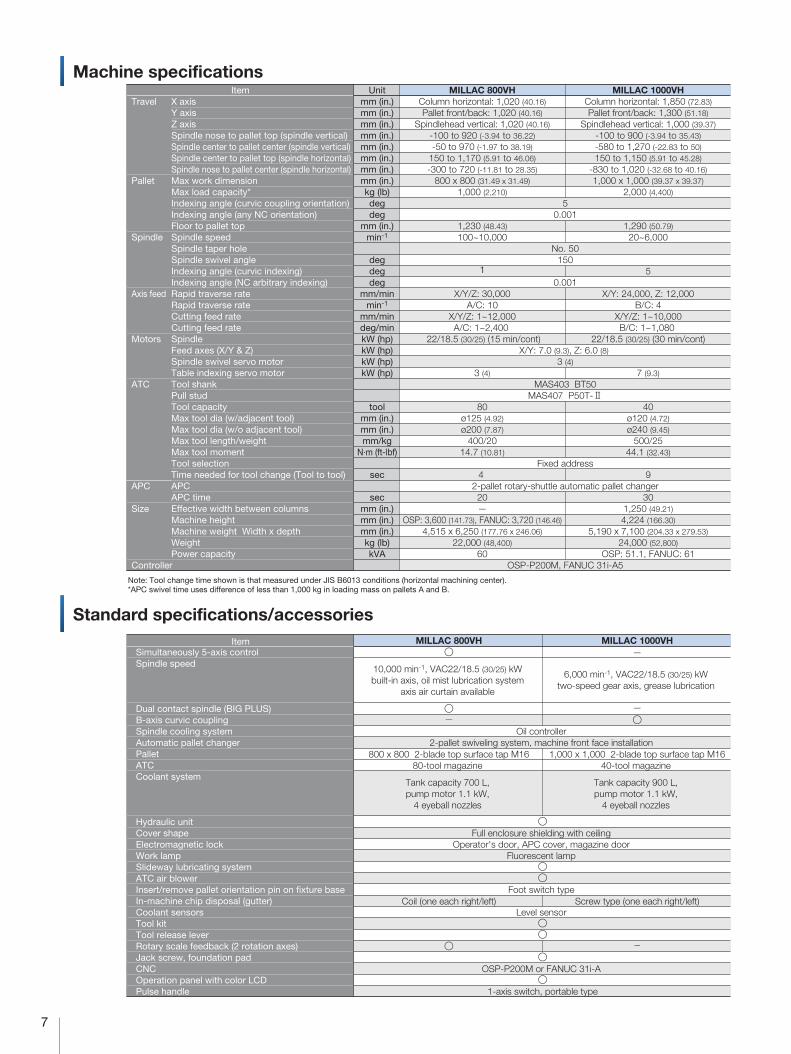
Machine specifications
Note: Tool change time shown is that measured under JIS B6013 conditions (horizontal machining center). *APC swivel time uses difference of less than 1,000 kg in loading mass on pallets A and B.
mm (in.)mm (in.)mm (in.)mm (in.)mm (in.)mm (in.)mm (in.)mm (in.)kg (lb)degdeg
mm (in.)min-1
degdegdeg
mm/minmin-1
mm/mindeg/minkW (hp)kW (hp)kW (hp)kW (hp)
toolmm (in.)mm (in.)mm/kg
N·m (ft-lbf)
sec
secmm (in.)mm (in.)mm (in.)kg (lb)kVA
UnitItem MILLAC 800VH MILLAC 1000VH
MILLAC 800VH MILLAC 1000VH
10,000 min-1, VAC22/18.5 (30/25) kW built-in axis, oil mist lubrication system
axis air curtain available
6,000 min-1, VAC22/18.5 (30/25) kW two-speed gear axis, grease lubrication
�
��
800 x 800 2-blade top surface tap M1680-tool magazine
Tank capacity 700 L, pump motor 1.1 kW,
4 eyeball nozzles
Coil (one each right/left)
�
�
��
1,000 x 1,000 2-blade top surface tap M1640-tool magazine
Tank capacity 900 L, pump motor 1.1 kW,
4 eyeball nozzles
Screw type (one each right/left)
�
Travel
Pallet
Spindle
Axis feed
Motors
ATC
APC
Size
Controller
Standard specifications/accessories
Column horizontal: 1,020 (40.16)Pallet front/back: 1,020 (40.16)
Spindlehead vertical: 1,020 (40.16)-100 to 920 (-3.94 to 36.22)-50 to 970 (-1.97 to 38.19)
150 to 1,170 (5.91 to 46.06)-300 to 720 (-11.81 to 28.35)
800 x 800 (31.49 x 31.49)1,000 (2,210)
1,230 (48.43)100~10,000
1
X/Y/Z: 30,000A/C: 10
X/Y/Z: 1~12,000A/C: 1~2,400
22/18.5 (30/25) (15 min/cont)
3 (4)
80ø125 (4.92)ø200 (7.87)
400/2014.7 (10.81)
4
20�
OSP: 3,600 (141.73), FANUC: 3,720 (146.46)4,515 x 6,250 (177.76 x 246.06)
22,000 (48,400)60
Column horizontal: 1,850 (72.83)Pallet front/back: 1,300 (51.18)
Spindlehead vertical: 1,000 (39.37)-100 to 900 (-3.94 to 35.43)-580 to 1,270 (-22.83 to 50)150 to 1,150 (5.91 to 45.28)
-830 to 1,020 (-32.68 to 40.16)1,000 x 1,000 (39.37 x 39.37)
2,000 (4,400)
1,290 (50.79)20~6,000
5
X/Y: 24,000, Z: 12,000B/C: 4
X/Y/Z: 1~10,000B/C: 1~1,080
22/18.5 (30/25) (30 min/cont)
7 (9.3)
40ø120 (4.72)ø240 (9.45)
500/2544.1 (32.43)
9
301,250 (49.21)4,224 (166.30)
5,190 x 7,100 (204.33 x 279.53)24,000 (52,800)
OSP: 51.1, FANUC: 61
50.001
No. 50150
0.001
X/Y: 7.0 (9.3), Z: 6.0 (8) 3 (4)
MAS403 BT50MAS407 P50T-2
Fixed address
2-pallet rotary-shuttle automatic pallet changer
OSP-P200M, FANUC 31i-A5
Simultaneously 5-axis controlSpindle speed
Dual contact spindle (BIG PLUS)B-axis curvic coupling Spindle cooling systemAutomatic pallet changer PalletATCCoolant system
Hydraulic unitCover shape Electromagnetic lock Work lampSlideway lubricating system ATC air blower Insert/remove pallet orientation pin on fixture base In-machine chip disposal (gutter) Coolant sensors Tool kit Tool release lever Rotary scale feedback (2 rotation axes) Jack screw, foundation pad CNC Operation panel with color LCDPulse handle
Oil controller 2-pallet swiveling system, machine front face installation
�
Full enclosure shielding with ceiling Operator's door, APC cover, magazine door
Fluorescent lamp ��
Foot switch type
Level sensor ��
�
OSP-P200M or FANUC 31i-A �
1-axis switch, portable type
X axis Y axisZ axisSpindle nose to pallet top (spindle vertical)Spindle center to pallet center (spindle vertical)Spindle center to pallet top (spindle horizontal) Spindle nose to pallet center (spindle horizontal)Max work dimension Max load capacity*Indexing angle (curvic coupling orientation)Indexing angle (any NC orientation)Floor to pallet topSpindle speed Spindle taper hole Spindle swivel angleIndexing angle (curvic indexing)Indexing angle (NC arbitrary indexing)Rapid traverse rateRapid traverse rateCutting feed rateCutting feed rateSpindleFeed axes (X/Y & Z)Spindle swivel servo motorTable indexing servo motorTool shankPull studTool capacityMax tool dia (w/adjacent tool)Max tool dia (w/o adjacent tool)Max tool length/weightMax tool momentTool selectionTime needed for tool change (Tool to tool)APCAPC time Effective width between columns Machine heightMachine weight Width x depth WeightPower capacity
�
� �
�
�
Item

8
Optional specifications/accessories
Chip conveyor Please contact an Okuma sales representative for details.
Optional spindle speed
Axis travel features Simultaneous 5-axis control APC specifications Pallet upper surface shape Thru-spindle coolantThru-spindle semi-dry unit Work lamp Pallet size ATC tool magazine capacity Status indicator Shower coolant system In-machine chip disposal (oil pan) Off machine chip disposal Chip bucket Dual contact spindle (BIG PLUS) Pull stud shapeChip air blowerWorkpiece washing gunAir gunCoolant tank Coolant pump Coolant temperature regulator Oil skimmerOil mist coolant Mist collector Raised machine setup High column spec Spindle nose rotate stopper Rotary scale feedback Scale feedback Foundation bolts/plates Temperature regulator in control panel
Reference tool (#50) Auto gauging *2
Ring gauge
�(Standard specifications)
6-APC, 8-APC, multi-pallet APC
□630 (when other than 2-APC selected)120 Tools
�
(Standard specifications)
Akamatsu Denki HVS-220
(Standard specifications)
T-slot 18 mm (30 mm thicker)1.5 MPa, 3.5 MPa, 7.0 MPa (back filter mounted separately)
Preps Additional halogen lamp fixed in 1 place
Yellow signal tower, 3-color signal tower Ceiling shower (2.2 kW pump added)
Various lift-up chip conveyors (see below)�
MAS 1, 90˚ Nozzle type
Main operation panel door side + APC door side Main operation panel door side + APC door side
700 L (hinge scraper conveyor), 900 L (with drum filter) 2.2 kW
Cooling only Belt system
�
���
X, Y, Z axes��
Stationary type touch sensor, moving type touch sensor�
FM radio�
X-axis: 1,850 mm, Y-axis: 1,600 mm�
4-APC, 6-APC, 8-APC, multi-pallet APC
ø1,250 mm60, 80, 120 Tools
Chip flushing (oil pan cleaning)
�
Showa Denki CRD-1500R
2 rotation axes
� Recommended specifications for chip disposal (optional specifications)
� Maximum tool dimensions
Max tool size (adjacent tools)
Max single tool size
� : Standard � : Selectable
Workpiece material Steel
Chip shape
In-machineconveyor(standard)
Lift-up chipconveyor
MILLAC 800VH: Coil type
MILLAC 1000VH: Screw type
Hinge type
Scraper type
Scraper (with drum filter)
Hinge type + scraper type (with drum filter)
FC Aluminum/Nonferrous Mixed (general use)
�
�
�
�
� (*1)
�
�
� (Dry)
� (Wet) With magnets
� (Wet) (*2)
�
�
�
� (*3)
�
�
� (*4)
�
�
�
*1) When there are many fine chips *2) When chips are longer than 100 mm *3) When chips are shorter than 100 mm *4) When there are few fine chips
Note: When dry-cutting be sure to clean away chips that have accumulated under the pallet or elsewhere in the machine as needed. Stairs may be necessary depending on the type of conveyor.
50400
ø100
ø125
[ø12
0]
ø69.
85
ø100
ø200
[ø24
0]
50400
ø69.
85
MILLAC 800VH
�
MILLAC 1000VHItem
MILLAC 800VH [ ] for MILLAC 1000VH
� Typical type of off machine chip disposal (lift-up conveyor)
Item
Shape
Hinge Scraper Scraper (w/drum filter) Hinge + Scraper (w/drum filter)
Automatic tool length compensation *1
100-10,000 min-1 (integral) B axis curvic coupling not used. B axis scale feedback required Spindle bearing lubricating oil needed.
*1. Including breakage detection *2. Indluding zero point compensation

9
�
�
�
�
Working ranges
Pallet dimensions
800 [1,000]
800
[1,0
00]
4�160640[4�200800]
4�16
064
0[4
�20
080
0]
8025
100
[125
]
30
30
4030
14.5
24-M16 depth 30
ø18
ø26100[125]
3618
ø50H7
ø20
118˚
36 18
30400270
M16
Center hole detail drawing
Tapped hole detail drawing
[ ] for MILLAC 1000VH
Trav
el 1
,020
(40.
16)
Trav
el 1
,020
(40.
16)
700
(27.
56)
250(9.84)
30˚90˚
30˚
1,00
0 (3
9.37
)
ø1,000
800
Travel 1,020 (40.16)
1,17
0 (4
0.06
)
510
(20.
08)
970 (38.19)
ø1,000
(39.37) 510
(20.
08)
Trav
el 1
,300
(51.
18)
Trav
el 1
,000
(39.
37)
700
(27.
56)
250
30˚90˚
30˚
1,10
0 (4
3.31
)
ø1,250
1,000 (39.37)
Travel 1,850 (72.83)
1,15
0 (4
5.28
)
650
(25.
59)
1,270 (50) 580 (22.83)
ø1,250
(49.21) 650
(25.
59)
1,020(40.16)
MILLAC 800VH MILLAC 1000VH
�
�
�

10
An OSP / Windows® Collaboration
Large 15-inch display
� � Screen is 2.1 times larger than before� � Huge increase in amount of information that can be displayed
Touch panel� � Direct manipulation of data� � Durable panel resists dirt and scratches
USB ports
Windows® - based Applications Machine Control Functions
Windows® Real-Time OS
High Performance NC Computer
Ethernet USB Servo Link DeviceNet™
An OSP / Windows® Collaboration OSP-P200M
The NC software developed by our “Single Source for Machine & Control” platform continues to provide advanced functions like Collision Avoidance System and other truly innovative machine control technologies.
A high-performanceNC computer in a flat panelPC-based expandability, highly reliable protection of machine control and data in tough factory environments––to give keep you constantly competitive and operating with optimum efficiency.
CAD/CAM System for Parts Machining
ADMAC-Parts
The advanced architecture
Networking and large program storage capacity (standard)
Easy-to-use operation panel
Windows is a registered trademark of Microsoft Corporation in the United States and other countries.DeviceNet is a trademark of Open DeviceNet Vendors Association.
� � Standard-equipped Ethernet specs ready for fast part program up/downloads with servers� Program storage expanded to 2 GB, plus program management with directory trees
� � 2 ports are standard. Various devices can be connected, like USB memory sticks for transfer of large NC programs, and bar code readers for production control applications.
Manual inputs, interactive inputs, CAD inputs-all kinds of ways to program with this comprehensive programming package.
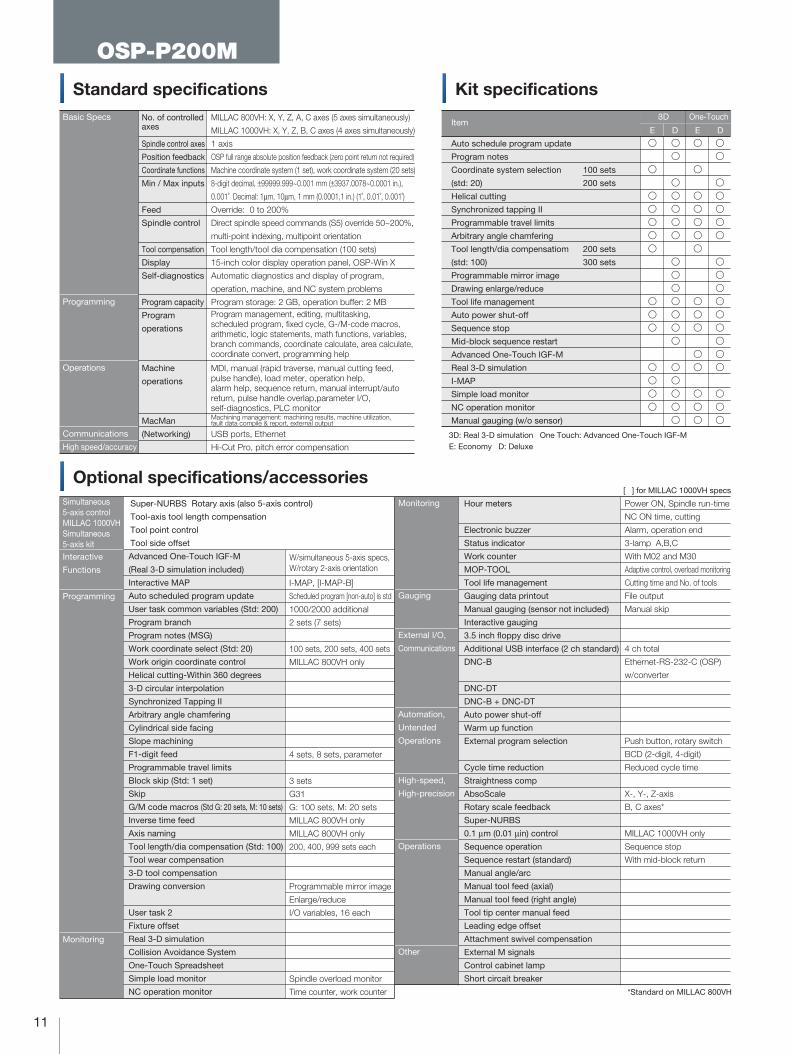
11
Standard specifications Kit specificationsBasic Specs
Programming
Operations
Communications
High speed/accuracy
No. of controlled axes
Spindle control axes
Position feedback
Coordinate functions
Min / Max inputs
Feed
Spindle control
Tool compensation
Display
Self-diagnostics
Program capacity
Program
operations
Machine
operations
MacMan
(Networking)
MILLAC 800VH: X, Y, Z, A, C axes (5 axes simultaneously)
MILLAC 1000VH: X, Y, Z, B, C axes (4 axes simultaneously)
1 axis
OSP full range absolute position feedback (zero point return not required)
Machine coordinate system (1 set), work coordinate system (20 sets)
8-digit decimal, ±99999.999~0.001 mm (±3937.0078~0.0001 in.),
0.001˚ Decimal: 1µm, 10µm, 1 mm (0.0001,1 in.) (1˚, 0.01˚, 0.001˚)
Override: 0 to 200%
Direct spindle speed commands (S5) override 50~200%,
multi-point indexing, multipoint orientation
Tool length/tool dia compensation (100 sets)
15-inch color display operation panel, OSP-Win X
Automatic diagnostics and display of program,
operation, machine, and NC system problems
Program storage: 2 GB, operation buffer: 2 MB
USB ports, Ethernet
Hi-Cut Pro, pitch error compensation
Item3D
OSP-P200M
Optional specifications/accessories
Interactive
Functions
Programming
Monitoring
Super-NURBS Rotary axis (also 5-axis control)
Tool-axis tool length compensation
Tool point control
Tool side offset
Advanced One-Touch IGF-M
(Real 3-D simulation included)
Interactive MAP
Auto scheduled program update
User task common variables (Std: 200)
Program branch
Program notes (MSG)
Work coordinate select (Std: 20)
Work origin coordinate control
Helical cutting-Within 360 degrees
3-D circular interpolation
Synchronized Tapping II
Arbitrary angle chamfering
Cylindrical side facing
Slope machining
F1-digit feed
Programmable travel limits
Block skip (Std: 1 set)
Skip
G/M code macros (Std G: 20 sets, M: 10 sets)
Inverse time feed
Axis naming
Tool length/dia compensation (Std: 100)
Tool wear compensation
3-D tool compensation
Drawing conversion
User task 2
Fixture offset
Real 3-D simulation
Collision Avoidance System
One-Touch Spreadsheet
Simple load monitor
NC operation monitor
I-MAP, [I-MAP-B]
Scheduled program [non-auto] is std
1000/2000 additional
2 sets (7 sets)
100 sets, 200 sets, 400 sets
MILLAC 800VH only
4 sets, 8 sets, parameter
3 sets
G31
G: 100 sets, M: 20 sets
MILLAC 800VH only
MILLAC 800VH only
200, 400, 999 sets each
Programmable mirror image
Enlarge/reduce
I/O variables, 16 each
Spindle overload monitor
Time counter, work counter
Auto schedule program update
Program notes
Coordinate system selection
(std: 20)
Helical cutting
Synchronized tapping II
Programmable travel limits
Arbitrary angle chamfering
Tool length/dia compensatiom
(std: 100)
Programmable mirror image
Drawing enlarge/reduce
Tool life management
Auto power shut-off
Sequence stop
Mid-block sequence restart
Advanced One-Touch IGF-M
Real 3-D simulation
I-MAP
Simple load monitor
NC operation monitor
Manual gauging (w/o sensor)
E D E D
100 sets
200 sets
200 sets
300 sets
One-Touch
Monitoring
Gauging
External I/O,
Communications
Automation,
Untended
Operations
High-speed,
High-precision
Operations
Other
[ ] for MILLAC 1000VH specs
Hour meters
Electronic buzzer
Status indicator
Work counter
MOP-TOOL
Tool life management
Gauging data printout
Manual gauging (sensor not included)
Interactive gauging
3.5 inch floppy disc drive
Additional USB interface (2 ch standard)
DNC-B
DNC-DT
DNC-B + DNC-DT
Auto power shut-off
Warm up function
External program selection
Cycle time reduction
Straightness comp
AbsoScale
Rotary scale feedback
Super-NURBS
0.1 µm (0.01 µin) control
Sequence operation
Sequence restart (standard)
Manual angle/arc
Manual tool feed (axial)
Manual tool feed (right angle)
Tool tip center manual feed
Leading edge offset
Attachment swivel compensation
External M signals
Control cabinet lamp
Short circait breaker
Power ON, Spindle run-time
NC ON time, cutting
Alarm, operation end
3-lamp A,B,C
With M02 and M30
Adaptive control, overload monitoring
Cutting time and No. of tools
File output
Manual skip
4 ch total
Ethernet-RS-232-C (OSP)
w/converter
Push button, rotary switch
BCD (2-digit, 4-digit)
Reduced cycle time
X-, Y-, Z-axis
B, C axes*
MILLAC 1000VH only
Sequence stop
With mid-block return
3D: Real 3-D simulation One Touch: Advanced One-Touch IGF-M E: Economy D: Deluxe
Program management, editing, multitasking, scheduled program, fixed cycle, G-/M-code macros, arithmetic, logic statements, math functions, variables, branch commands, coordinate calculate, area calculate, coordinate convert, programming help
MDI, manual (rapid traverse, manual cutting feed, pulse handle), load meter, operation help, alarm help, sequence return, manual interrupt/auto return, pulse handle overlap,parameter I/O, self-diagnostics, PLC monitorMachining management: machining results, machine utilization, fault data compile & report, external output
�
�
�
�
�
�
�
�
�
�
�
�
�
�
�
�
�
�
�
�
�
�
�
�
�
�
�
�
�
�
�
�
�
�
�
�
�
�
�
�
�
�
�
�
�
�
�
�
�
�
�
�
�
�
�
�
�
�
�
�
�
�
�
�
�
�
�
W/simultaneous 5-axis specs, W/rotary 2-axis orientation
Simultaneous 5-axis controlMILLAC 1000VHSimultaneous 5-axis kit
*Standard on MILLAC 800VH

12
FANUC 31i-A5
Software kitBasic Specs
Programming
Operations
Communications
No. of controlled axes
No. of spindle control axes
Position feedback
Coordinate functions
Min / Max inputs
Feed
Spindle control
Tool compensation
Display
Self-diagnostics
Program capacity
Program
operations
Machine
operations
(Networking)
MILLAC 800VH: X, Y, Z, A, C axes (5 axes simultaneously)
MILLAC 1000VH: X, Y, Z, B, C axes (4 axes simultaneously)
1 axis
Absolute position feedback command
Coordinate system settings, workpiece coordinate system, coordinate rotation
8-digit decimal, ±99999.999~0.001 mm (±3937.0078~0.0001 in.),
0.001˚ Decimal: 1µm, 10µm, 1 mm (0.0001,1 in.) (1˚, 0.01˚, 0.001˚)
F5 digit direct command, feedrate override, rapid traverse override
S5 digit direct command
Tool diameter and length correction (99 sets)
10.4-inch color display operational panel
Program memory capacity 512 KB, No. of registered programs 63
Tape memory, edit, fixed cycles, 1 optional block skip function
Calling subprograms, programmable data input,
macro executor
3-dimensional coordinate conversion
Pulse generator, dry run, machine block
Backlach compensation, memory-type pitch error compensation
Mirror image, 3-dimensional manual jog feed
RS-232-C interface, memory card input/output
Kit specifications Optional Specifications · Options
Software kit
AI contouring
control2kit
Simultaneous
5-axis kit
Display of machine utilization time/No. of parts
Custom macro
Helical interpolation
Background editing
Tool life management
Rigid tapping
Japanese language display
Software kit
Nanosmoothing
AI contouring control2
Maximum number of read-ahead blocks 600
Data server function 1 GB
Tool point control
3-D cutter radius comp
Interpolation type straightness compensation
Program memory capacities
Registered programs
Workpiece coordinates
Custom macros
Corner R arbitrary angle chamfering
Programmable mirror image
Scaling
Optional block skip change
Slope machining command
Fast skip
Polar coordinate interpolation
3rd, 4th reference point return
Smooth interpolation
NURBS interpolation
Automatic corner override
Inverse time feed
No. of read-ahead blocks extension
Tool compensations
Tool compensation memory C
Tool length compensation
Manual handle interrupt
Program restart
Tool offset
F1-digit feed
FS15 tape format
Tool point center rotation
Tool point control
Tool tilt control
External M code
Automatic power shutoff
Fixture offset
Workpiece mount error compensation
Data server
1 MB, 2 MB, 4 MB, 8 MB
1,000, 2,000 (to 1 MB), 4,000 (2 MB +)
48 sets, 300 sets
Additional common variables 600
9
Max no. of look-ahead blocks: 1,000
200, 400, 499, 999, 2,000
[on tool axis]
[manual feed]
1 GB, 4 GB

13
MILLAC 800VHDimensional drawing, installation drawing
�OSP-P200M / ATC 80 tool specifications
Lift-up conveyor (Opt)
Coolant tank drain valve
4,515 (177.76)
1,23
0(4
8.43
)
770
(30.31
)34
0(13
.39)
2,66
0 (1
04.9
2)
300
(11.
81)
5,28
5 (2
08.0
7)
1,36
5(5
3.74
)
4,51
5 (1
77.7
6)2,
325
(52.
17)
1,020 (40.16) travel
1,02
0 tra
vel
(40.1
6)
4,415 (173.82)
(650)
6,250 (246.06)3,660 (144.09) 100
(3.94)
1,360 (53.54)
1,900(75.20)
1,290(50.79)
2,970(116.93)
1,500 (59.06)90(3.54)
100(3.94)
100(3.94)
150
(5.9
1)
1,90
0 (b
ed)
3,35
5 (1
32.0
9)1,
195
(47.
05)
3,300 (129.92) (bed)
3,50
0 (1
37.8
0)1,
000
(Max
wor
k he
ight
)
3,60
0 (1
41.7
3)
100
(3.9
4)
Travel1,020(40.16)
625(24.61)
1,250(49.21)
1,155(45.47)
6,250(246.06)
1,500(59.06)
100(3.94)
(Max
work
piece
heigh
t)
Pallet top
ø1,000(max work dia)(max work dia)(Max work dia)
(Max
wor
k he
ight
)
14
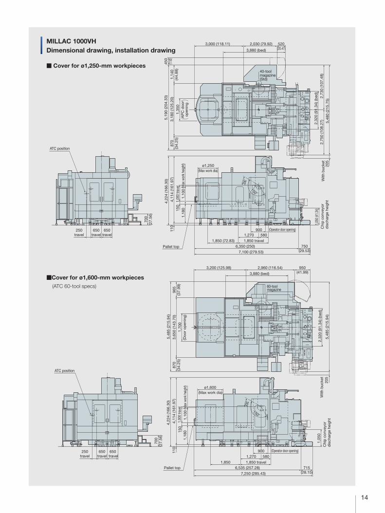
MILLAC 1000VHDimensional drawing, installation drawing
� Cover for ø1,250-mm workpieces
�Cover for ø1,600-mm workpieces (ATC 60-tool specs)
650travel
700
(27.
56)
650travel
250travel
ATC position
Chi
p c
onve
yor
dis
char
ge h
eigh
t
150˚
30˚
4,22
4 (1
66.3
0)
1,270
1,850 travel1,850 (72.83)
ø1,250
6,350 (250)
1,05
0 (4
1.34
)
750(29.53)7,100 (279.53)
580
4,11
4 (1
61.9
7)
1,18
01,
100
(Max
work
piece
heigh
t)(M
ax w
orkpie
ce he
ight)
1,00
0 tra
vel
150
(Max work dia)
900 (Operator door opening)110
205
AP
C d
oor
open
ing
With
buc
ket
3,000 (118.11) 2,030 (79.92)
3,880 (bed)
520(20.47)
5,19
0 (2
04.3
3)
1,35
0
450
(17.92
)1,
140
(44.
88)
3,18
0 (1
25.2
0)
2,75
0 (1
08.2
7)2,
730
(107
.48)
2,32
0 (9
1.34
) (b
ed)
5,48
0 (2
15.7
5)
870
(34.
25)
40-toolmagazine (Std)
650 travel
700
(27.
56)
Chi
p c
onve
yor
dis
char
ge h
eigh
t 20
5
650travel
250travel
150˚
30˚
4,22
4 (1
66.3
0)
1,270
1,850 travel1,850
ø1,600
6,535 (257.28)
1,05
0
5,48
5 (2
15.9
4)
715(28.15)7,250 (285.43)
580
4,11
4 (1
61.9
7)
1,18
01,
100
(Doo
r op
enin
g)
(Max work dia)
900 (Operator door opening)
With
buc
ket
1,00
0 tra
vel
110
3,65
0 (1
43.7
0)1,
700
5,48
5 (2
15.9
4)
3,200 (125.98) 2,960 (116.54)
60-toolmagazine
950(41.99)
870
(34.
25)
965
(37.
99)
Pallet top
Pallet top
3,880 (bed)
2,32
0 (9
1.34
) (b
ed)
150
ATC position
(max work dia)
(Max
wor
k he
ight
)(M
ax w
ork
heig
ht)
(Max
wor
k he
ight
)

OKUMA Corporation, OGUCHI-CHO, NIWA-GUN, AICHI 480-0193, JAPAN • TEL (0587) 95-7825 • FAX (0587) 95-6074 � The specifications, illustrations, and descriptions in this brochure vary in different markets and are subject to change without notice. Consult your local Okuma representative for specific end-user requirements. Pub No. MILLAC800/1000V-(1)-400 (Apr 2010) Printed in Japan
When using Okuma products, always read the safety precautionsmentioned in the instruction manual and attached to the product.
This product is subject to the Japanese government Foreign Exchange and Foreign Trade Control Act with regard to security controlled items; whereby Okuma Corporation should be notified prior to its shipment to another country.