4x4 hdmi fst matrix switcher installation guide - … · 1 introduction the 4x4 hdmi fst matrix...
TRANSCRIPT

1
IntroductionThe 4x4 HDMI FST Matrix Switcher provides high definitionvideo sources plus multi-channel digital audio from anyof the four HDMI sources to the remote displays at thesame time.
Features and Benefits• Distribute content from any of the four HDMI sources
to any connected display• Device and display switching via push buttons, IR
remote control, RS-232 control and Ethernet control• Supports HDMI Deep Color, full 3D and HDCP 2.0• Supports Fast Switch and no blinking technology• Supports stereo & 7.1 channel digital audio• Metal housing with wall mount support
Package Contents• 4x4 HDMI FST Matrix Switcher• Power adapter• Remote control and IR blaster cable• Mounting ears and screws(6)• Software CD• Installation guide
04-0854A
4x4 HDMI FST MatrixSwitcher
Installation Guide

2
Figure 1: Front Panel Layout
• Source status LED: HDMI input source status LEDindicator. Steady blue light when HDMI source isconnected. Each HDMI IN connector has a LEDindicator
• IR sensor: IR sensor for receiving the IR commandsfrom IR remote
• Output selection button: Press the Output button(s)to select the output display
• Input selection button: Press the Input button(s) toselect the input signal
Layout
Figure 2: Rear Panel Layout
• RS-232: RS-232 control port• Ethernet: IP (Ethernet) control port
HDMI IN(1-4)
HDMI OUT(1-4)
RS-232 Ethernet
Source statusLED (1-4)
IR sensor
Input selectionbutton
Outputselection button
+5V DC
IR Receiver

3
• HDMI IN (1-4): Connects to your HDMI source'sHDMI output via HDMI cables (cables not included)
• HDMI OUT (1-4): Connect your HDMI displayshere
• IR Receiver: Connect your IR blaster cable here• +5V DC: Connect your power adapter here
Hardware Installation1. Power off all source devices and displays.2. Connect up to four HDMI source devices to the
Matrix Switcher's HDMI input ports by HDMI cables(cables not included).
3. Connect up to 4 HDMI displays to the MatrixSwitcher's HDMI output ports by HDMI cables (cablesnot included).
4. For PC software control over the input/outputselection and related settings, please connect theRS-232 cable and Ethernet cable to the MatrixSwitcher's serial port and Ethernet port.
Note: If you want to control device switchingthrough RS-232 port, connect an RS-232 cable to thePC only. If you want to control device switchingthrough Ethernet port, connect both RS-232 cableto the PC and Ethernet cable to a router or switch onyour network at the beginning.
5. Plug the power adapter into the Matrix Switcher'spower jack, then plug the power adapter into areliable power outlet. The Matrix Switcher is poweredon automatically.
6. Power on all devices connected to the switch.7. The Matrix Switcher is now ready for use.

4
OperationThere are four ways to control the input and output:1. Selection button on the front panel; 2. IR remote control;3. RS-232 control port; 4. IP (Ethernet) control port.
Control over Input selection buttonRefer to Figure 3 for the position of each control button:
OUTPUT -/ Preset
INPUT - /EDID Learn
OUTPUT + /Save
INPUT + /Default EDID
Figure 3
upper LED
lower LED
INPUT / OUTPUT Selection1. Press INPUT + (the bottom, right button) or
INPUT - (the bottom, left button) button to chooseyour input source."+" means increasing in the number of the input,"-" means decreasing. The lower LED will displaythe selected input number.
2. Press OUTPUT + (the top, right button) or OUTPUT- (the top, left button) to choose your output display."+" means increasing in the number of the display,and "-" means decreasing. The upper LED willdisplay the selected output number.
3. After both output and input are selected, the LEDwill blink twice, and the setting is taking effect now.The selected output will display the input sourceyou selected.

5
Save Mapping
1. Press INPUT + or INPUT - button to choose yourinput.
2. Press OUTPUT + or OUTPUT - button to chooseyour output. Once the your preferred output isselected, keep pressing the OUTPUT+ button (thatis, Save mapping button), the upper LED will showd. The Matrix Switcher is in saving mode now.Note: Continue to hold down the OUTPUT+ button(Save mapping button) until instructed otherwise.
3. Press INPUT + or INPUT - button to choose achannel from 0-7. The channel you choose is thechannel you save this mapping in.
4. Release the OUTPUT+ button (Save mappingbutton) now, the upper and lower LED will blinktwice. The mapping is saved now.
Delete Saved Mapping1. Press and hold down the OUTPUT - button (that is,
Preset button). Note: Continue to hold down thePreset button until instructed otherwise.
2. When the upper LED shows P, press INPUT + orINPUT - button to choose the channel from 0-7. Thechannel you choose is the channel you want to erasethe mapping memory.
3. Release the Preset button now, the upper and lowerLED will blink twice. The mapping is erased now.
Learning Default EDID1. Press INPUT + or INPUT - button to choose an
input you want to learn the default EDID. Onceyour preferred input is selected, keep pressing theINPUT+ button (that is, Default EDID button).

6
Note: Continue to hold down the Preset buttonuntil instructed otherwise.
2. Press OUTPUT + or OUTPUT - button, the upperLED will show E, and the lower LED will show d.The Matrix Switcher is in default EDID learningmode.
3. Press OUTPUT + or OUTPUT - button to choosethe default EDID mode from 1-8.
1) Full-HD(1080p@60)-24bit 2D & 2ch2) Full-HD(1080p@60)-24bit 2D & 7.1ch3) Full-HD(1080p@60)-24bit 3D & 2ch4) Full-HD(1080p@60)-24bit 3D & 7.1ch5) Full-HD(1080i@60)(720p@60)-24bit 2D & 2ch6) Full-HD(1080i@60)(720p@60)-24bit 2D & 7.1ch7) Full-HD(1080p@60)-36bit 2D & 2ch8) Full-HD(1080p@60)-36bit 2D & 7.1ch
4. Release the Default EDID button, the upper andlower LED will blink twice. The selected defaultEDID is learned now.
EDID Learning Mode1. Press INPUT + or INPUT - button to choose an
input you want to learn. Once your preferred inputis selected, keep pressing the INPUT- button (thatis, EDID Learning button).
Note: Please don't let go of the EDID Learningbutton until instructed to do so.
2. Press OUTPUT + or OUTPUT - button, the upperLED will show E, and the lower LED will showL.The Matrix Switcher is in EDID learning modenow.

7
3. Press OUTPUT + or OUTPUT - button to select aEDID port from 1-4.
4. Release the EDID Learning button now, the upperand lower LED will blink twice. The EDID is learnedby your selected output.
Control over IR Remote ControlINPUT / OUTPUT SelectionSelect your input and output by pressing the circledbuttons below. See Figure 4.Take button B for example, button B is on the crossedpoint of input 2 and output 1. So when you press buttonB, the signals from input 2 will display on output 1.
Figure 4

8
Save Mapping1. After the preferred input/output is selected, press
SAVE. The upper LED on Matrix Switcher will showd.
2. Press button A-H to select your storage channel.Note: Buttons A-H represent storage channels 1-8.
3. Press the TAKE button. The mapping has beensaved.
Delete Saved Mapping1. If you want to delete a saved mapping, press the
PRESET button. The upper LED on Matrix Switcherwill show P.
2. Press button A-H to select your storage channel.Note: Buttons A-H represent storage channels 1-8.
3. Press the TAKE button. The mapping has beendeleted.
Learning Default EDID1. Press the DEFAULT EDID button . The upper LED
will show E and lower LED will show d.2. Press button A-H to select your default EDID mode.
Note: Buttons A-H represent default EDID mode 1-8. Please refer to page 6 for the default EDID list.
3. Press button I-IV to select a desired input. Note:Buttons I-IV represent input source 1-4.
4. Press the TAKE button.

9
EDID Learning Mode1. Press the LEARN button. The upper LED will show
E and lower LED will show L.2. Press button A-H to select EDID port.3. Press button I-IV to select a desired input. Note:
Buttons I-IV represent input source 1-4.4. Press theTAKE button.
Disable Output1. If you want to disable any of your outputs, press the
MUTE button.2. Press button A-D to select your output display.
Note: Buttons A-D represent output display 1-4.3. Press the TAKE button.
Others: Function Key DefinitionRefer to Table 1 below for the definition of each button:
Table 1

10
Control over RS-232 Control PortMake sure the RS-232 cable (not included) is connected toyour PC computer before proceeding. The software onlycan be used under Windows 7 and XP.1. Double click the setup file in the HDMI FST Matrix
Switcher folder of your driver CD to start theprogram.
Figure 5
2. Select your COM port from the COM port selectionmenu, then click the Connection button.When successfully connected, the Connection statuswill show Connected, see Figure 6a.Note: Make sure the status is connected before yougo to the next section. If the status is not connected,the connection status will show Connecting(orange) or Disconnected (red). See Figure 6b and6c respectively.
Figure 6a Figure 6b Figure 6c
COM portselection menu
Connectionstatus
Connectionbutton
Mute
RS-232Control
NetworkControl
Power On/Off Button

11
INPUT / OUTPUT SelectionAfter sucessful connection, select your input/output byclicking the crossed cell of the input and output.See Figure 7a for example, all four input sources outputto different displays. Input source 1 to display 1, source2 to display 2, source 3 to display 3, source to display 4.See Figure 7b for example, input source 1 outputs to all4 displays.
Figure 7a Figure 7b
Disable OutputIf you want to disable the output display(s), click theMute bullet on the right side. The bullet will turn redwhen disabled. Click the red bullet again to enable thedisplay.
Figure 8

12
EDID SetupClick the EDID button on the main menu to enter EDIDsetup.
1. Learning Default EDID:Select the default EDID mode from the drop downlist, select the input, then click Learn.
2. Load EDID File:Select Input from the drop down list, then click Loadto load the EDID file.
3. Create EDID FileClick Create to create a new EDID file.
4. View EDIDSelect Input from the drop down list, then clickView to view the EDID information.
Figure 9

13
Mapping1. Save mapping:
Select mapping from 1-8, then click Save.2. Preset mapping:
Select mapping from 1-8, then click Recall.3. Rename mapping:
Rename the mapping, then click Confirm.
Firmware updateFirmware updates are released periodically, updates arenot needed if your switcher is working properly. Checkfor any firmware updates at SIIG website: www.siig.com/download.
1. Click Load File to select firmware file.2. Click Break.3. Quickly remove and reconnect the power adapter.4. Click Start to begin the firmware update procedure.
Figure 10
Break LoadFile
Start

14
Control over Ethernet Control Port
Configuring the Ethernet Control PortMake sure an RS-232 cable (not included) is connected toyour PC and an Ethernet cable (not included) is connectedto a router or switch on your network before proceeding.
1. Double click the setup file in HDMI FST MatrixSwitcher folder on your driver CD.
2. Select your COM port from the COM port selectionmenu, then click the Connection button. See Figure5 on page 11.
3. Make sure the Connection status is Connected. Atthe main menu, click NETWORK tab.
Figure 11
SaveRecall
Confirm
Figure 12
Network

15
5. Fill in the IP and MASK column so that the MatrixSwitcher is in the same IP domain as your network.Then click Write to Device. (Ask your Network/ITadministrator or use network utilities IPconfig andPing for the correct network settings)
Figure 14
Figure 13
RS232
Read FromDevice
4. At the Device Setting window, select RS232, thenclick Read From Device. See Figure 13.

16
8. The Ethernet connection is established now. Youcan control the Matrix Switcher through Ethernetport now. Go to pages 11 through 13 for the varioussoftware device control options.
Note: The serial cable can be disconnected if deviceswitching via RS-232 control port is not needed.
6. At the prompted Complete window, click OK.7. Select Ethernet, type in the IP, then click OK. See
Figure 15.
Figure 15
EthernetOK
IP

17
Ethernet Device ControlMake sure you have already configured the MatrixSwitch's Ethernet control port before proceeding.
1. Double click the setup file in the HDMI FST MatrixSwitcher folder of your driver CD to start the program.
2. Select Network control icon, then click theConnection button When successfullyconnected, the Connection status will showConnected.
3. Go to pages 11 through 14 for the various softwaredevice control options.
18
Application
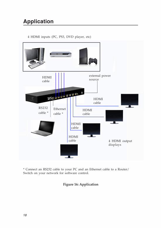
HDMIcable
HDMIcable
HDMIcable
HDMIcable
external powersource
HDMIcable
4 HDMI inputs (PC, PS3, DVD player, etc)
4 HDMI outputdisplays
Figure 16: Application
RS232
cable *Ethernet
cable *
* Connect an RS232 cable to your PC and an Ethernet cable to a Router/Switch on your network for software control.

19
Technical Support and WarrantyQUESTIONS? SIIG’ s Online Support has answers! Simply visit our web siteat www.siig.com and click Support. Our online support database is updateddaily with new drivers and solutions. Answers to your questions could bejust a few clicks away. You can also submit questions online and a technicalsupport analyst will promptly respond.SIIG offers a 3-year manufacturer warranty with this product. This warrantycovers the original purchaser and guarantees the product to be free of anydefects in materials or workmanship for three (3) years from the date ofpurchase of the product.SIIG will, at our discretion, repair or replace (with an identical product orproduct having similar features and functionality) the product if defective inmaterials or workmanship. This warranty gives you specific legal rights, andyou may also have other rights which vary from state to state. Please see ourweb site for more warranty details.If you encounter any problems with this product, please follow the proceduresbelow.A) If it is within the store's return policy period, please return the product tothe store where you purchased it.B) If your purchase has passed the store's return policy period, please followthese steps to have the product repaired or replaced.
Step 1: Submit your RMA request. Go to www.siig.com, click Support,then Request A Product Replacement to submit a request to SIIG RMAor fax a request to 510-657-5962. Your RMA request will be processed, ifthe product is determined to be defective, an RMA number will be issued.Step 2: After obtaining an RMA number, ship the product.• Properly pack the product for shipping. All software, cable(s) and any
other accessories that came with the original package must be included.• Clearly write your RMA number on the top of the returned package.
SIIG will refuse to accept any shipping package, and will not beresponsible for a product returned without an RMA number postedon the outside of the shipping carton.
• You are responsible for the cost of shipping to SIIG. Ship the productto the following address:SIIG, Inc.6078 Stewart AvenueFremont, CA 94538-3152, USARMA #:
• SIIG will ship the repaired or replaced product via Ground in the U.S.and International Economy outside of the U.S. at no cost to thecustomer.

4x4 HDMI FST Matrix Swicher is a trademark of SIIG, Inc. SIIG and the SIIG logo are registeredtrademarks of SIIG, Inc. Microsoft and Windows are registered trademarks of Microsoft Corporation.Mac and Mac OS are registered trademarks of Apple Inc. All other names used in this publication arefor identification only and may be trademarks of their respective owners.
October, 2013 Copyright © 2013 by SIIG, Inc. All rights reserved.
PRODUCT NAME4x4 HDMI FST Matrix Switcher
FCC RULES: TESTED TO COMPLY WITH FCC PART 15, CLASSB OPERATING ENVIRONMENT: FOR HOME OR OFFICE USE
FCC COMPLIANCE STATEMENT:This device complies with part 15 of the FCC Rules. Operation issubject to the following two conditions: (1) This device may not causeharmful interference, and (2) this device must accept any interferencereceived, including interference that may cause undesired operation.
THE PARTY RESPONSIBLE FOR PRODUCT COMPLIANCE
SIIG, Inc.6078 Stewart AvenueFremont, CA 94538-3152, USAPhone: 510-657-8688
About SIIG, Inc.Founded in 1985, SIIG, Inc. is a leading manufacturer of IT connectivitysolutions (including Serial ATA and Ultra ATA Controllers, FireWire, USB,and legacy I/O adapters) that bridge the connection between Desktop/Notebook systems and external peripherals. SIIG continues to grow byadding A/V and Digital Signage connectivity solutions to our extensiveportfolio. All centered around the distribution and switching of A/V signalsover CAT5/6, these products include matrix switches, distribution amplifiers,extenders, converters, splitters, cabling, and more.SIIG is the premier one-stop source of upgrades and is committed toproviding high quality products while keeping economical and competitiveprices. High-quality control standards are evident by one of the lowestdefective return rates in the industry. Our products offer comprehensiveuser manuals, user-friendly features, and most products are backed by alifetime warranty.SIIG products can be found in many computer retail stores, mail ordercatalogs, and e-commerce sites in the Americas, as well as through majordistributors, system integrators, and VARs.