4d ct lung planning - department of biomedical imaging...
TRANSCRIPT

4D CT For Lung Planning4D CT For Lung Planning
25 June 2009
Dr Ho Gwo FuangClinical Oncologist
University of Malaya Medical Centre
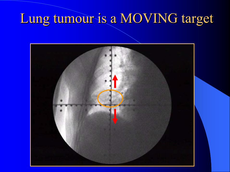
Lung Lung tumourtumour is a MOVING target is a MOVING target
Problems of Treating a Moving Problems of Treating a Moving TargetTarget
Interfraction movement
Intrafraction movement √
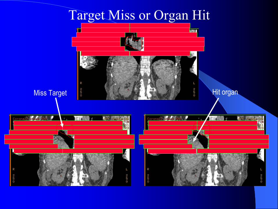
Target Miss or Organ Hit
Miss Target Hit organ
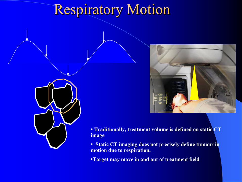
Respiratory MotionRespiratory Motion
• Traditionally, treatment volume is defined on static CT image
• Static CT imaging does not precisely define tumour in motion due to respiration.
•Target may move in and out of treatment field

ICRU 52 and 60ICRU 52 and 60
CTV
PTV2 cm
2 cm
1 cm1 cm
•GTV is expanded to CTV (microscopic spread) and PTV (set-up and other errors)
•To account for respiratory movement, margins are added to the clinical target volume
• Treated volume ↑
• Increases the normal tissue dose and limits the target dose
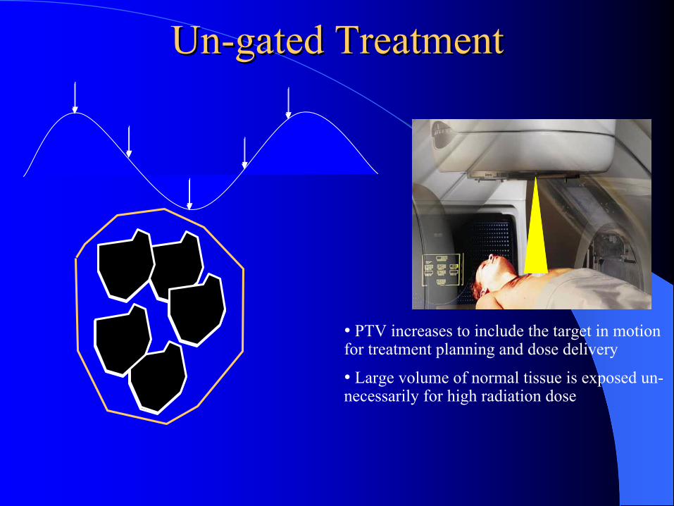
UnUn--gated Treatmentgated Treatment
• PTV increases to include the target in motion for treatment planning and dose delivery
• Large volume of normal tissue is exposed un-necessarily for high radiation dose
Target Movement Target Movement -- 3D Solution3D Solution
Expand the PTV to cover the maximum ranges of target motions along all three directions
Problems:Difficult to generate isodose distributions conforming to the moving target such as lung tumor with 3DCRTUnable to minimize the doses to the surrounding normal tissuesTherefore limiting total dose and dose fraction sizes
Challenge Challenge
Goal –How do you accurately deliver appropriate dose distributions conforming to a moving lung target and meantime effectively minimize doses to surrounding normal lung tissues?
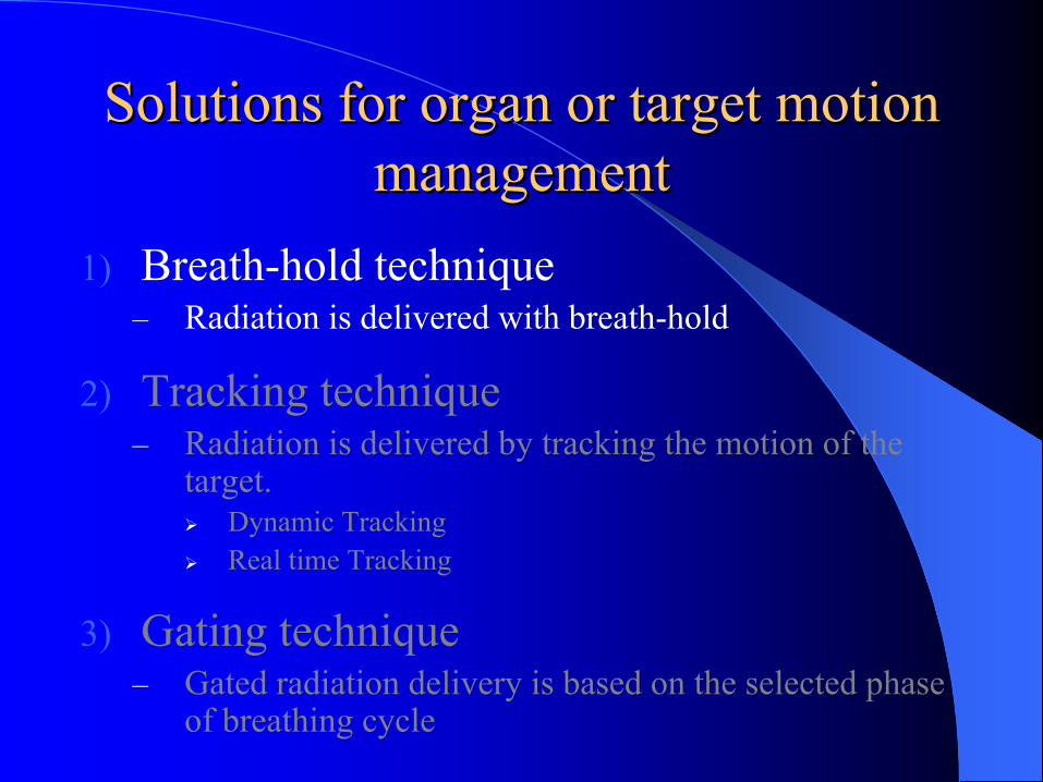
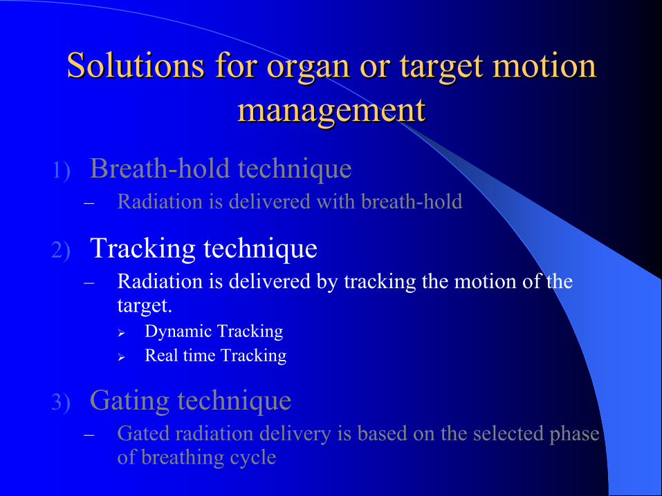
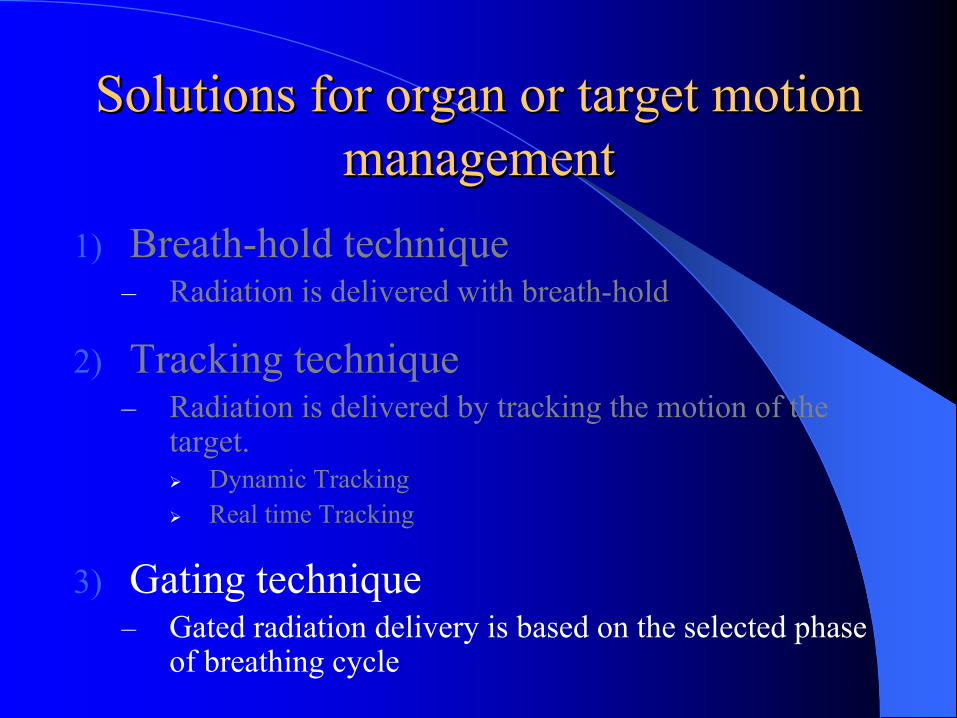
Solutions for organ or target motion Solutions for organ or target motion managementmanagement
1) Breath-hold technique– Radiation is delivered with breath-hold
2) Tracking technique– Radiation is delivered by tracking the motion of the
target.Dynamic TrackingReal time Tracking
3) Gating technique– Gated radiation delivery is based on the selected phase
of breathing cycle
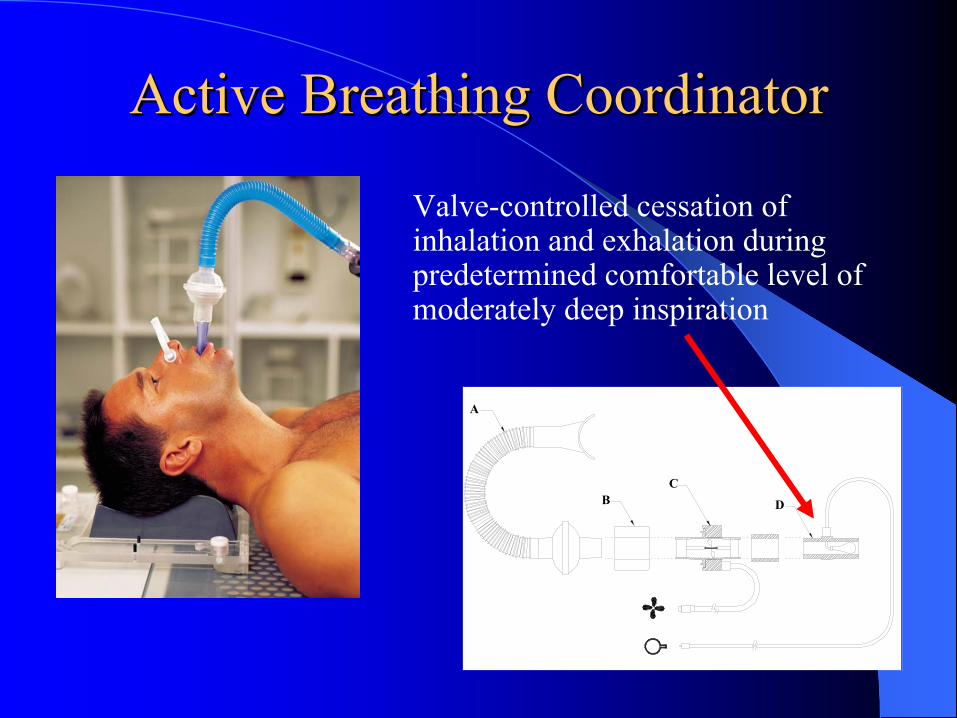
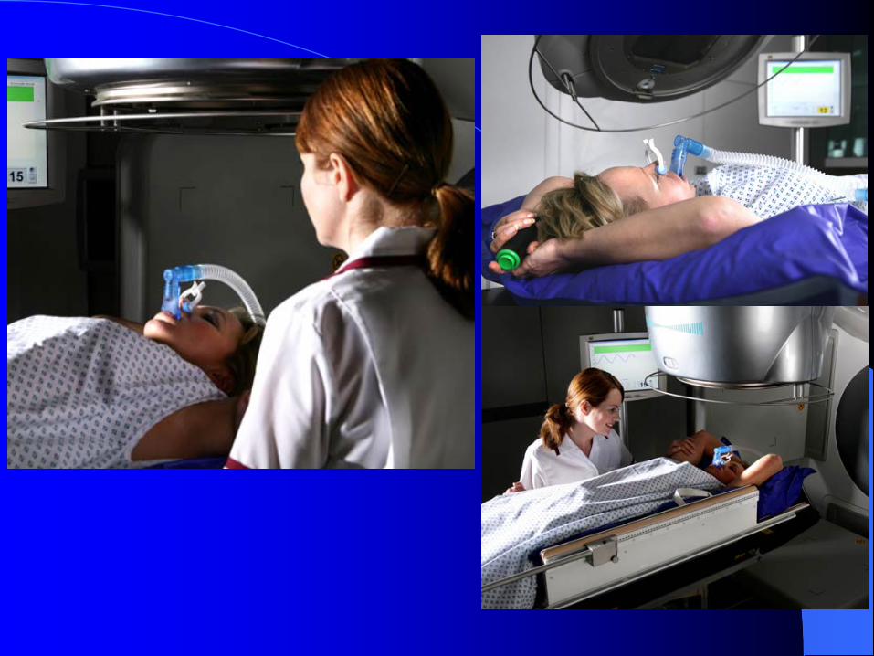
Active Breathing CoordinatorActive Breathing Coordinator
Valve-controlled cessation of inhalation and exhalation during predetermined comfortable level of moderately deep inspiration
A
BC
D
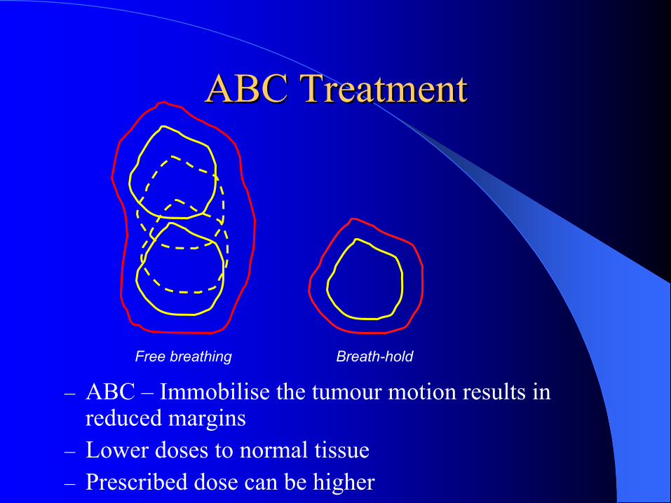
ABC TreatmentABC Treatment
– ABC – Immobilise the tumour motion results in reduced margins
– Lower doses to normal tissue– Prescribed dose can be higher
Free breathing Breath-hold
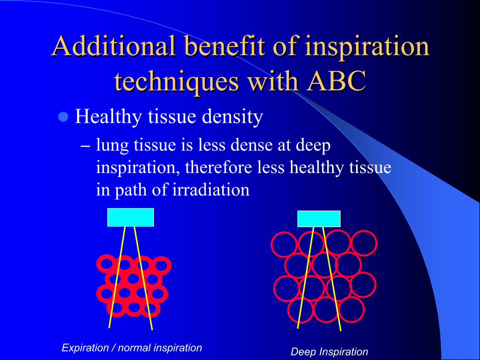
Additional benefit of inspiration Additional benefit of inspiration techniques with ABCtechniques with ABC
Healthy tissue density– lung tissue is less dense at deep
inspiration, therefore less healthy tissue in path of irradiation
Expiration / normal inspiration Deep Inspiration
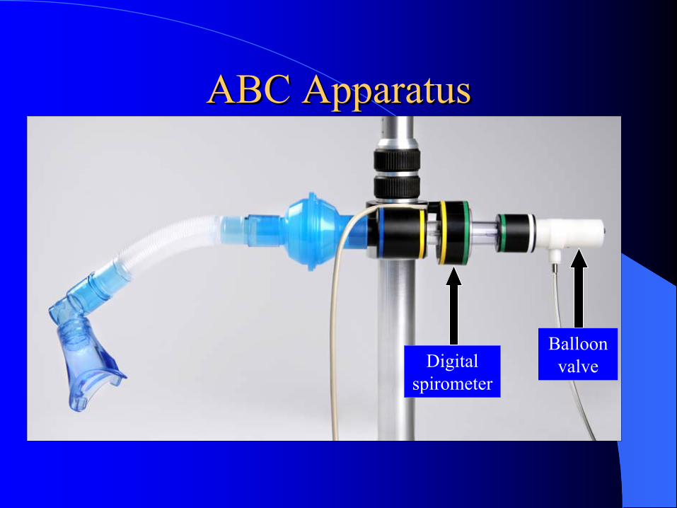
ABC ApparatusABC Apparatus
Digital spirometer
Balloon valve
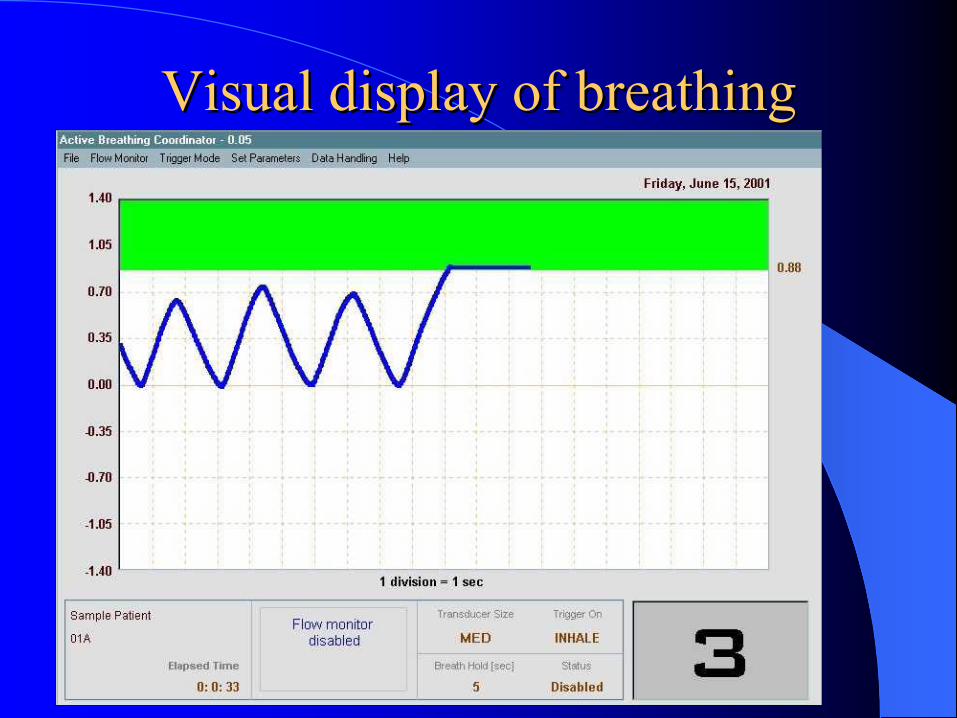
Visual display of breathing Visual display of breathing motionmotion
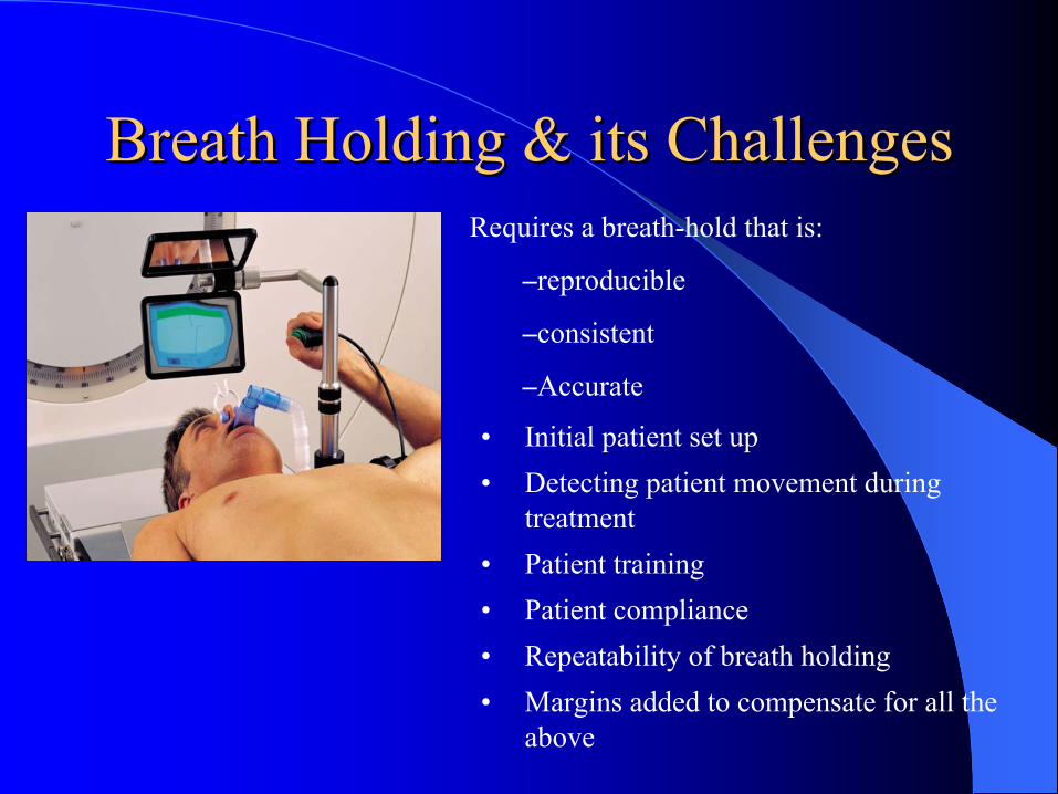
Breath Holding & its ChallengesBreath Holding & its Challenges
• Initial patient set up• Detecting patient movement during
treatment• Patient training• Patient compliance• Repeatability of breath holding• Margins added to compensate for all the
above
Requires a breath-hold that is:
–reproducible
–consistent
–Accurate
Solutions for organ or target motion Solutions for organ or target motion managementmanagement
1) Breath-hold technique– Radiation is delivered with breath-hold
2) Tracking technique– Radiation is delivered by tracking the motion of the
target.Dynamic TrackingReal time Tracking
3) Gating technique– Gated radiation delivery is based on the selected phase
of breathing cycle
TrackingTrackingDynamic tracking– e.g. Cyberknife, RTRT system
Real time tracking – e.g. Calypso System
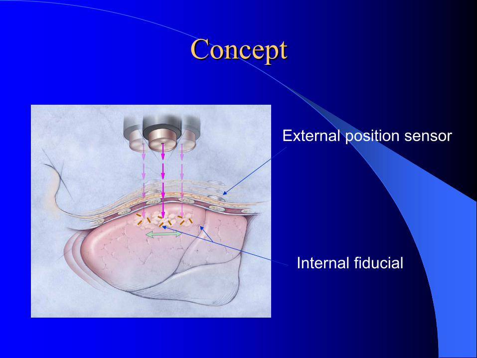
ConceptConcept
External position sensor
Internal fiducial
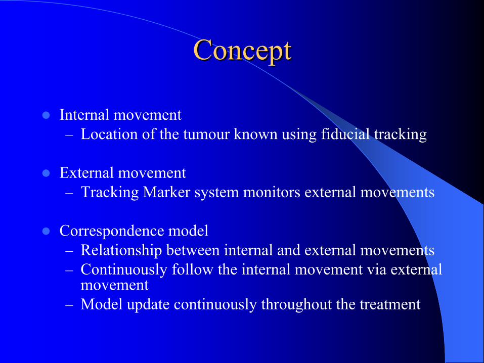
Internal movement– Location of the tumour known using fiducial tracking
External movement– Tracking Marker system monitors external movements
Correspondence model– Relationship between internal and external movements– Continuously follow the internal movement via external
movement– Model update continuously throughout the treatment
ConceptConcept

CyerknifeCyerknife
DiagnosticX-Ray Sources
Image Detector
Treatment Couch
Linear Accelerator
Robotic Arm

Prediction AlgorithmPrediction Algorithm200ms delay allows robot to smooth jerky offset calculations
Based on pattern searching1) Look at the record of model results just before 2) Compare this pattern with the record of model results over a
longer period of elapsed time 3) Find the position at which they match. Sample the model
position 200ms later – this is the prediction
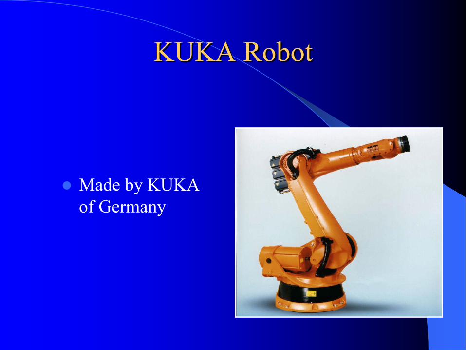
KUKA Robot KUKA Robot
Made by KUKA of Germany
Solutions for organ or target motion Solutions for organ or target motion managementmanagement
1) Breath-hold technique– Radiation is delivered with breath-hold
2) Tracking technique– Radiation is delivered by tracking the motion of the
target.Dynamic TrackingReal time Tracking
3) Gating technique– Gated radiation delivery is based on the selected phase
of breathing cycle
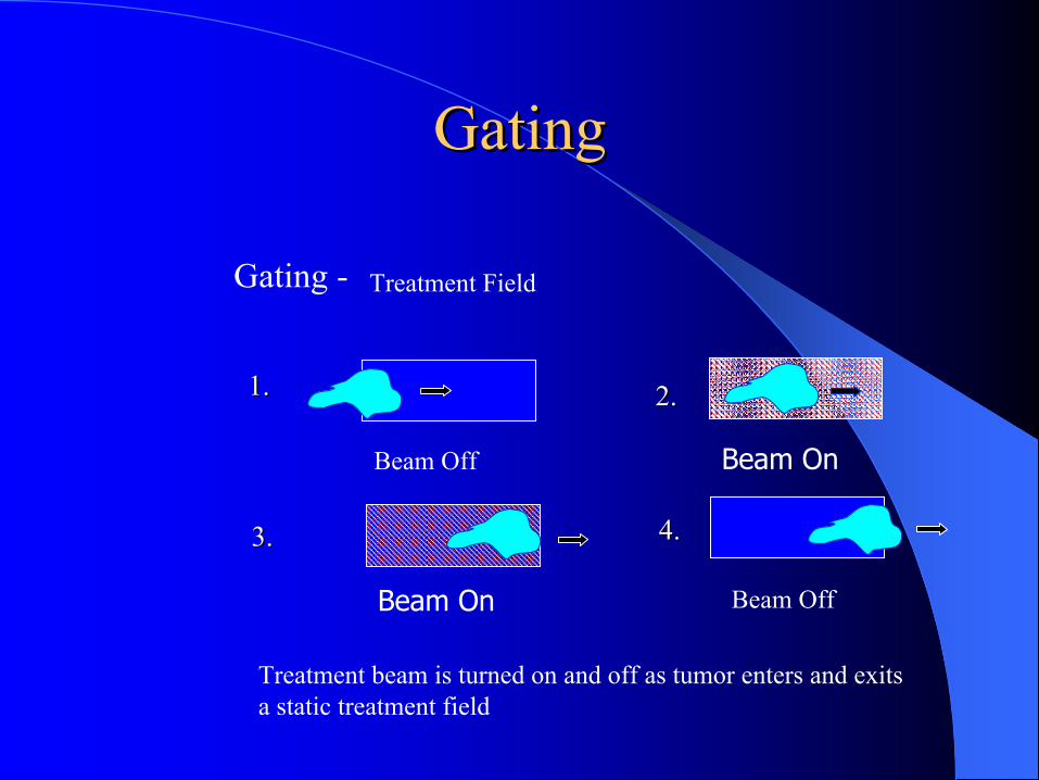
Beam Off
Beam OffBeam On
Beam On
Treatment Field
1.1. 2.2.
3.3. 4.4.
Gating -
Treatment beam is turned on and off as tumor enters and exits a static treatment field
GatingGating
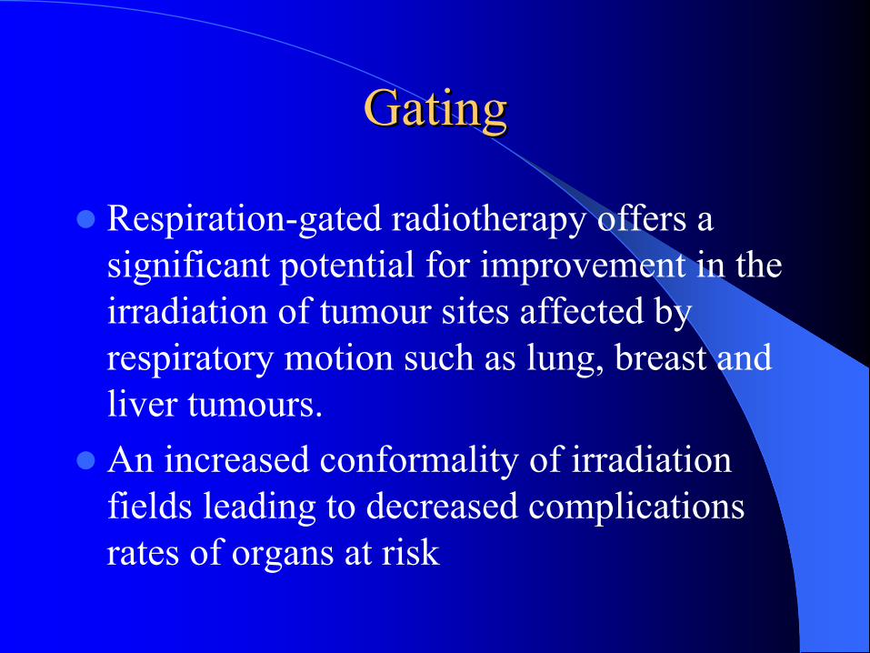
GatingGating
Respiration-gated radiotherapy offers a significant potential for improvement in the irradiation of tumour sites affected by respiratory motion such as lung, breast and liver tumours. An increased conformality of irradiation fields leading to decreased complications rates of organs at risk

Respiratory motion solutionsRespiratory motion solutionsBreath-hold techniques (e.g. ABC)– Uncomfortable for patients, limited applicability (MSKCC: 7/13
patients)– Increases treatment time (MSKCC: 17 to 33 minutes for conventional
RT)Respiratory gating– Residual motion within
gating window– Increases treatment time– Baseline shift
4D Radiotherapy– Hardware/Software
complexity
-0.6
-0.4
-0.2
0
0.2
0.4
0.6
0 5 10 15 20
Tim e (s)
Dis
plac
emen
t (cm
)
Exhale gate
Inhale Gate
4D Radiotherapy4D Radiotherapy
The explicit inclusion of the temporal changes in anatomy during the imaging, planning and delivery of radiotherapy
4D Solution for Organ Motion4D Solution for Organ Motion
4D CT provides insight into organ motionduring respiration, with volumetric anatomic data setTreatment planning explicitly accounts for the internal target motionThis can be implemented at various levels of complexity
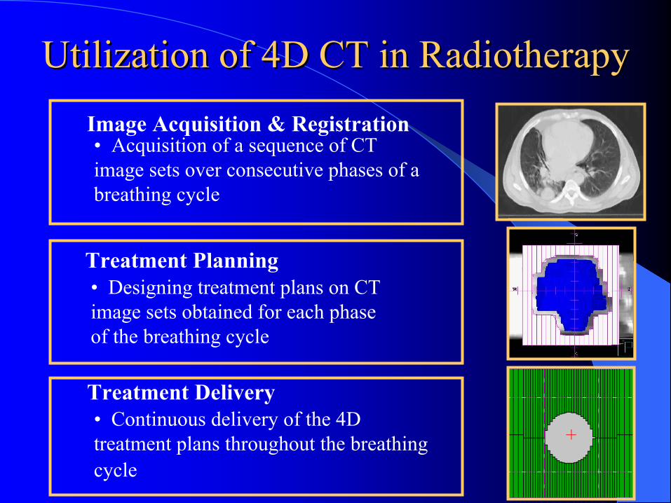
Utilization of 4D CT in RadiotherapyUtilization of 4D CT in Radiotherapy
Treatment Planning
Image Acquisition & Registration• Acquisition of a sequence of CT image sets over consecutive phases of a breathing cycle
• Designing treatment plans on CT image sets obtained for each phase of the breathing cycle
• Continuous delivery of the 4D treatment plans throughout the breathing cycle
Treatment Delivery
CT Motion ArtifactsCT Motion Artifacts
CT data acquisition is serial– Data at adjacent couch positions are acquired serially
Collection of projection data one slice after another in combination with motion of the scanned object leads to significant interplay – Depending on the relative motion of the advancing
scan plane and the tumour, different artifacts can be imaged

3D CT - Distorted images, incorrect anatomical Distorted images, incorrect anatomical
positions, volumes or shapespositions, volumes or shapes
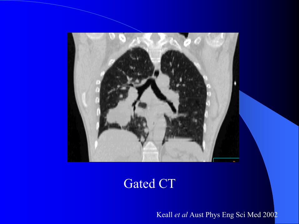
Gated CT
Keall et al Aust Phys Eng Sci Med 2002
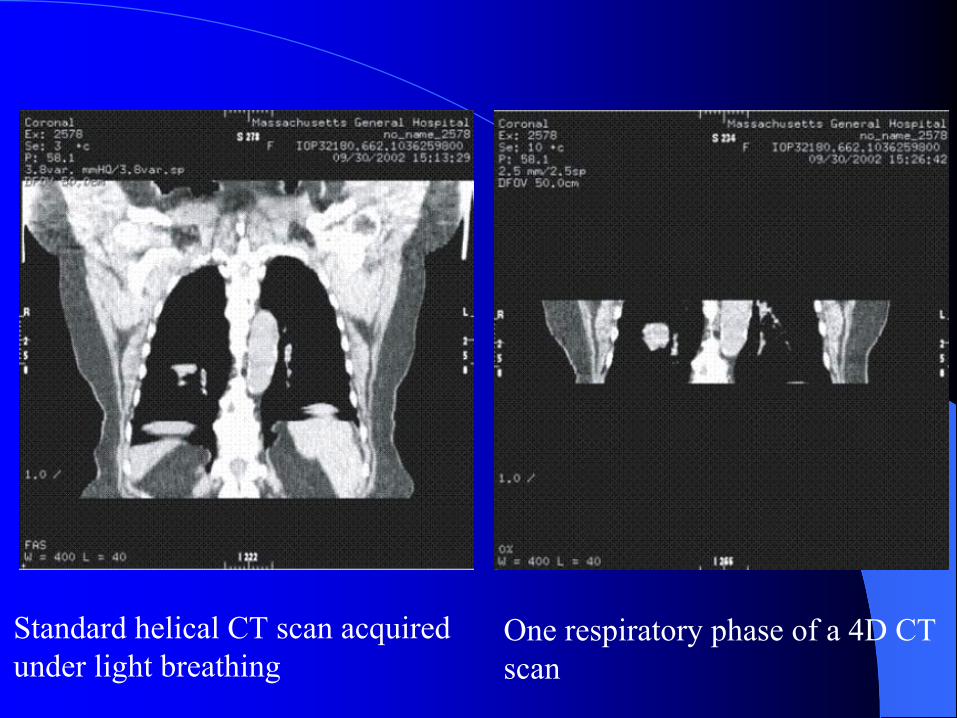
Standard helical CT scan acquired under light breathing
One respiratory phase of a 4D CTscan
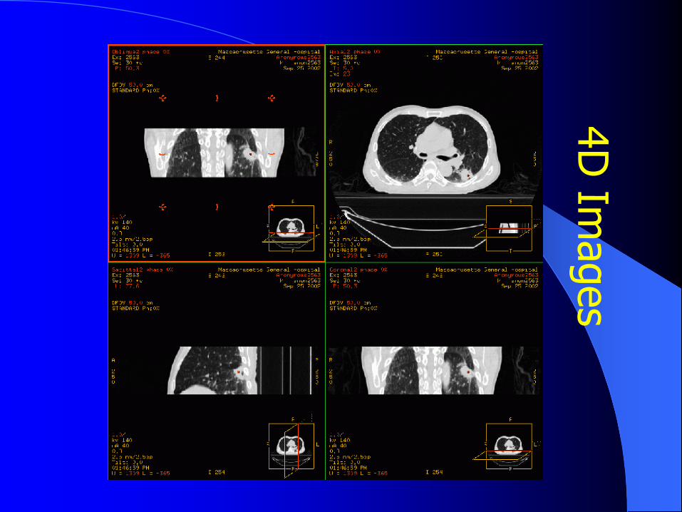
4D Im
ages
4D CT Scan4D CT Scan
Assumptions– Organ motions such as lungs are related to the motions
of an external marker
Concepts– If patients can breathe periodically and regularly, the
CT image acquisition is fast enough to generate many images at all phases in a series of respiratory cycles
– When the scan is done, all the images of the selected phase are retrospectively organized to form 4D video images
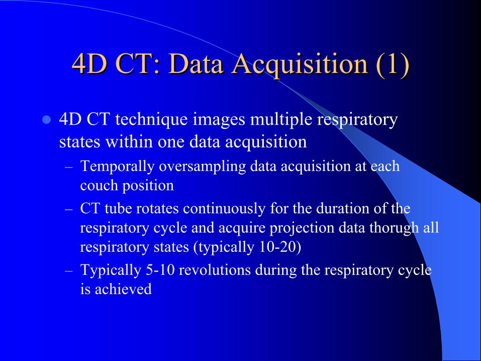
4D CT: Data Acquisition (1)4D CT: Data Acquisition (1)
4D CT technique images multiple respiratory states within one data acquisition– Temporally oversampling data acquisition at each
couch position– CT tube rotates continuously for the duration of the
respiratory cycle and acquire projection data thorugh all respiratory states (typically 10-20)
– Typically 5-10 revolutions during the respiratory cycle is achieved
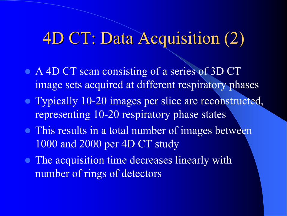
4D CT: Data Acquisition (2)4D CT: Data Acquisition (2)
A 4D CT scan consisting of a series of 3D CT image sets acquired at different respiratory phasesTypically 10-20 images per slice are reconstructed, representing 10-20 respiratory phase statesThis results in a total number of images between 1000 and 2000 per 4D CT studyThe acquisition time decreases linearly with number of rings of detectors
External Sorting SignalExternal Sorting Signal
After 4D CT data acquisition and image reconstruction –
in order to sort these images into specific temporally coherent volumes, additional information is required
One such sorting signal is the rise and fall of the abdominal surface, as a surrogate for respiratory motion
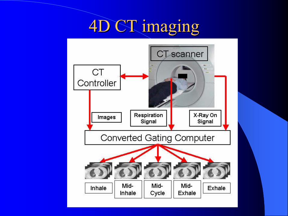
4D CT imaging4D CT imaging
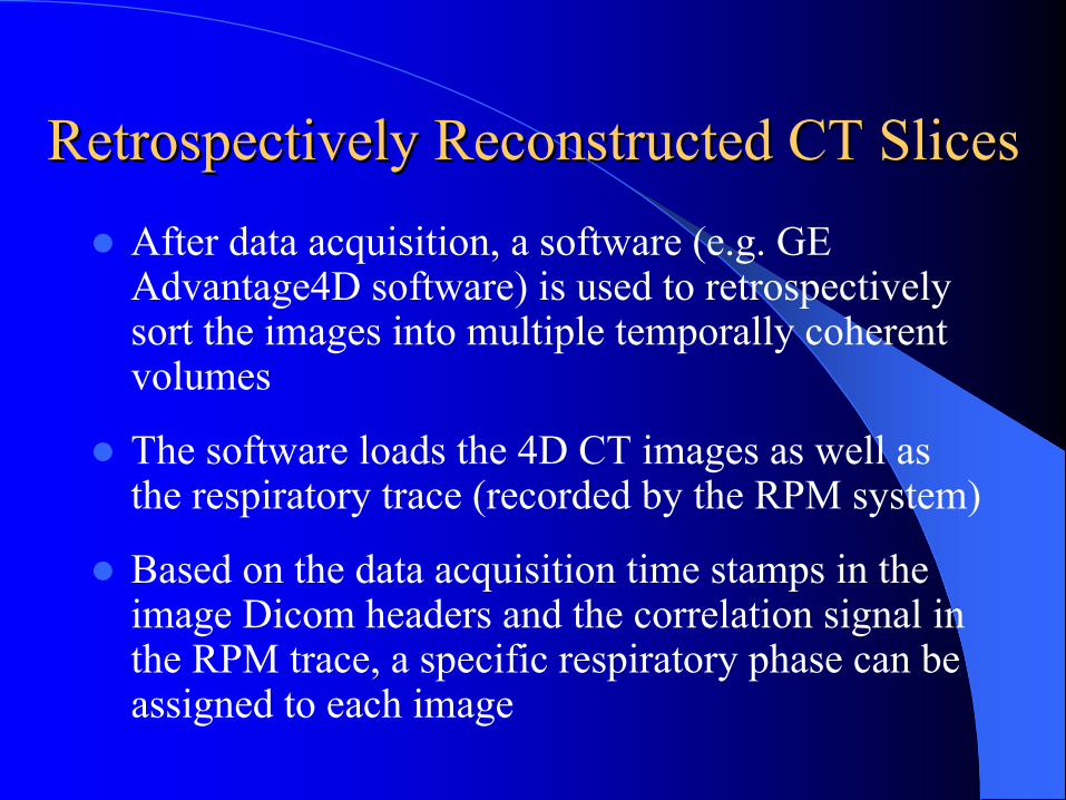
Retrospectively Reconstructed CT SlicesRetrospectively Reconstructed CT SlicesAfter data acquisition, a software (e.g. GE Advantage4D software) is used to retrospectively sort the images into multiple temporally coherent volumes
The software loads the 4D CT images as well as the respiratory trace (recorded by the RPM system)
Based on the data acquisition time stamps in the image Dicom headers and the correlation signal in the RPM trace, a specific respiratory phase can be assigned to each image
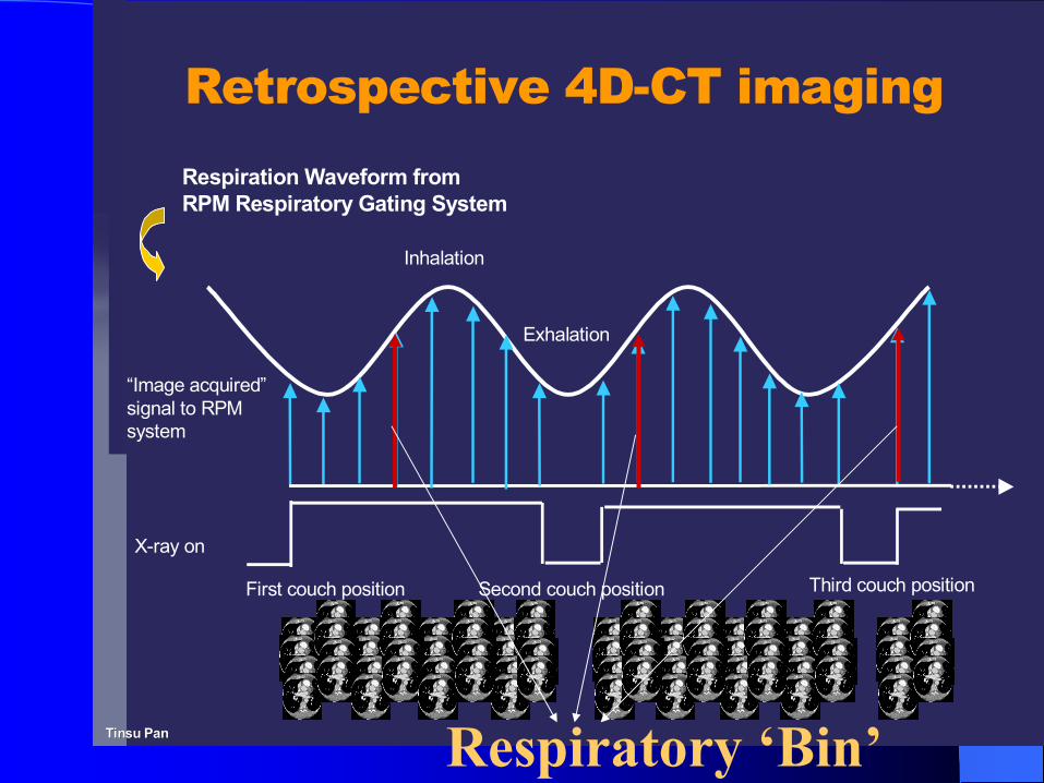
Respiration Waveform from RPM Respiratory Gating System
X-ray on
Exhalation
Inhalation
First couch position Second couch position Third couch position
“Image acquired”signal to RPM system
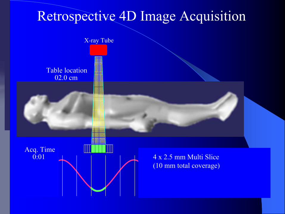
Retrospective 4D-CT imaging
Tinsu Tinsu PanPan Respiratory ‘Bin’
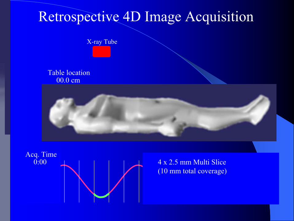
0:00
00.0 cm
Retrospective 4D Image Acquisition
4 x 2.5 mm Multi Slice(10 mm total coverage)
X-ray Tube
Table location
Acq. Time
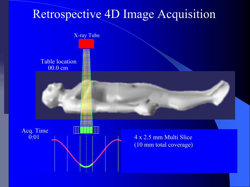
0:01
00.0 cm
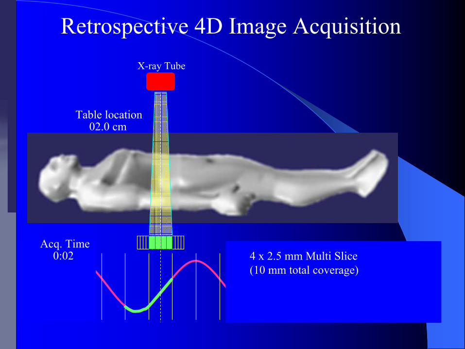
Retrospective 4D Image Acquisition
4 x 2.5 mm Multi Slice(10 mm total coverage)
X-ray Tube
Table location
Acq. Time
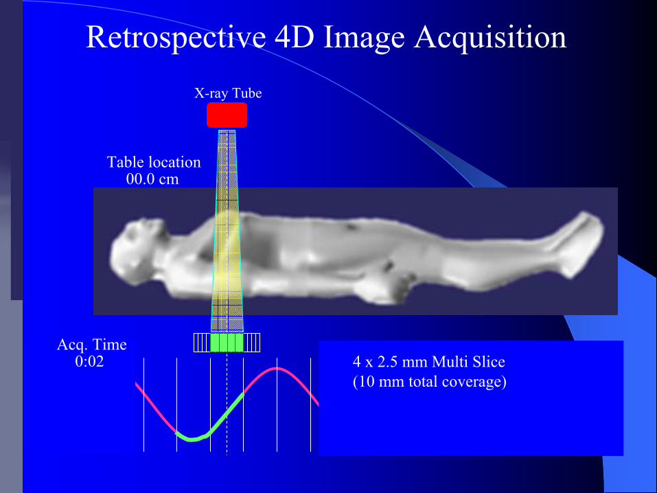
0:02
00.0 cm
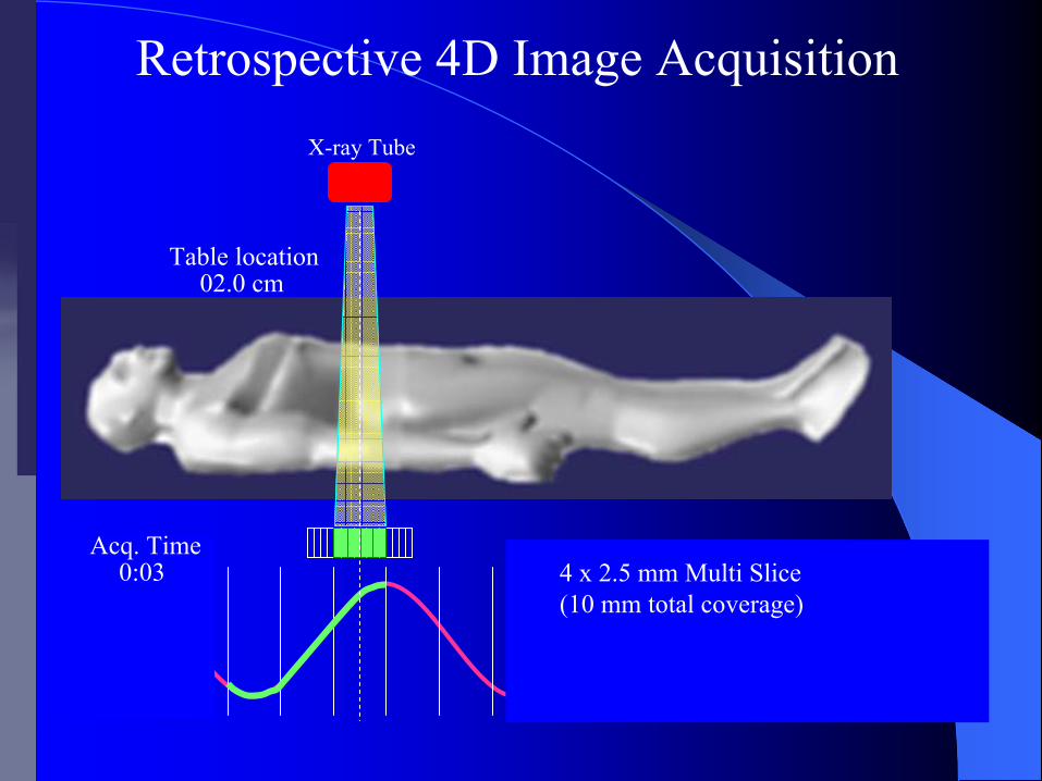
4 x 2.5 mm Multi Slice(10 mm total coverage)
X-ray Tube
Table location
Acq. Time
Retrospective 4D Image Acquisition
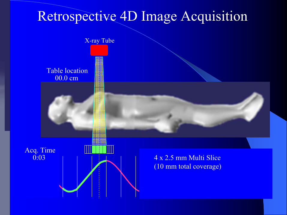
0:03
00.0 cm
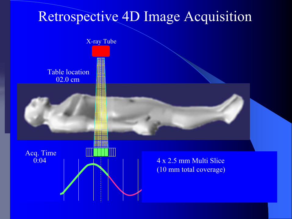
4 x 2.5 mm Multi Slice(10 mm total coverage)
X-ray Tube
Table location
Acq. Time
Retrospective 4D Image Acquisition

0:04
00.0 cm
4 x 2.5 mm Multi Slice(10 mm total coverage)
X-ray Tube
Table location
Acq. Time
Retrospective 4D Image Acquisition
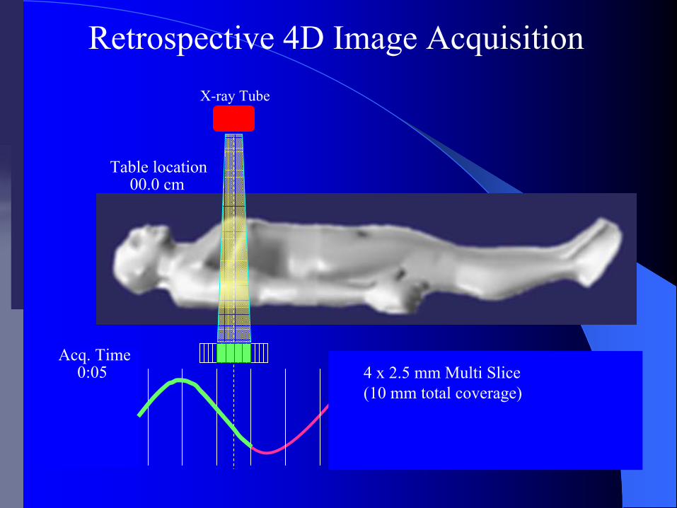
0:05
00.0 cm
4 x 2.5 mm Multi Slice(10 mm total coverage)
X-ray Tube
Table location
Acq. Time
Retrospective 4D Image Acquisition
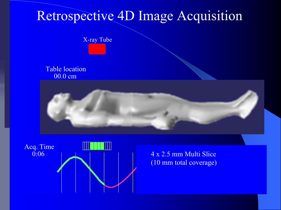
0:06
00.0 cm
4 x 2.5 mm Multi Slice(10 mm total coverage)
X-ray Tube
Table location
Acq. Time
Retrospective 4D Image Acquisition
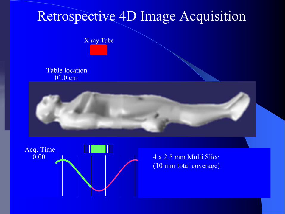
0:00
01.0 cm
4 x 2.5 mm Multi Slice(10 mm total coverage)
X-ray Tube
Table location
Acq. Time
Retrospective 4D Image Acquisition
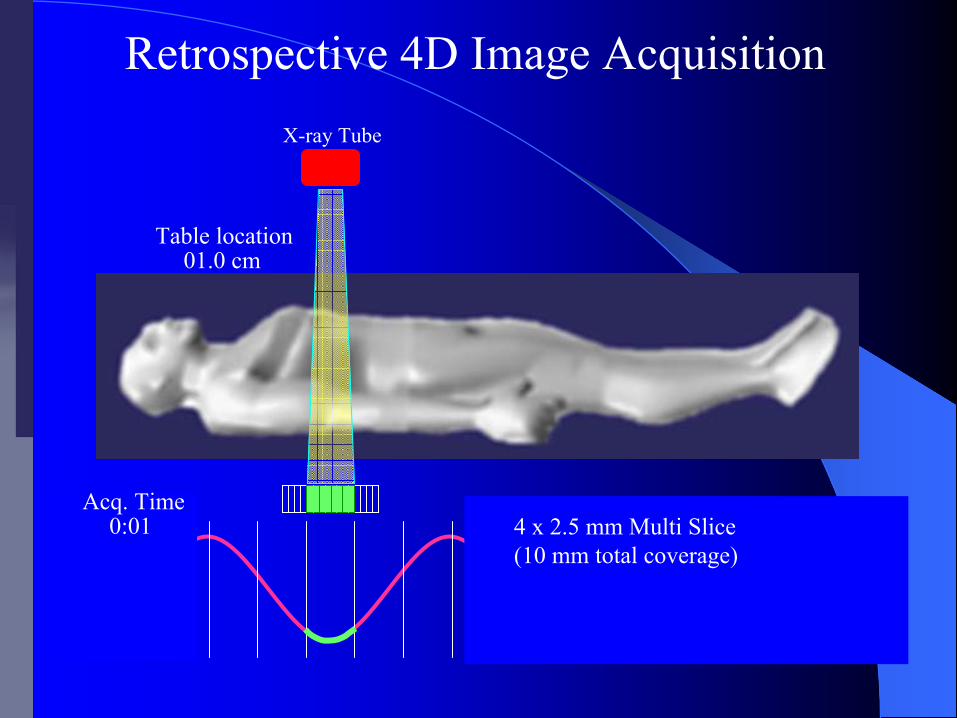
0:01
01.0 cm
4 x 2.5 mm Multi Slice(10 mm total coverage)
X-ray Tube
Table location
Acq. Time
Retrospective 4D Image Acquisition

0:02
01.0 cm
4 x 2.5 mm Multi Slice(10 mm total coverage)
X-ray Tube
Table location
Acq. Time
Retrospective 4D Image Acquisition

0:03
01.0 cm
4 x 2.5 mm Multi Slice(10 mm total coverage)
X-ray Tube
Table location
Acq. Time
Retrospective 4D Image Acquisition

0:04
01.0 cm
4 x 2.5 mm Multi Slice(10 mm total coverage)
X-ray Tube
Table location
Acq. Time
Retrospective 4D Image Acquisition

0:05
01.0 cm
4 x 2.5 mm Multi Slice(10 mm total coverage)
X-ray Tube
Table location
Acq. Time
Retrospective 4D Image Acquisition
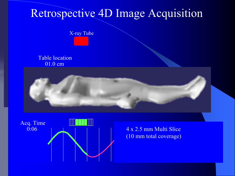
0:06
01.0 cm
4 x 2.5 mm Multi Slice(10 mm total coverage)
X-ray Tube
Table location
Acq. Time
Retrospective 4D Image Acquisition
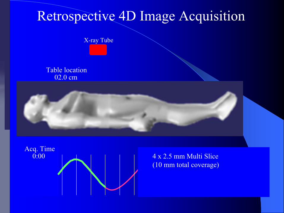
0:00
02.0 cm
4 x 2.5 mm Multi Slice(10 mm total coverage)
X-ray Tube
Table location
Acq. Time
Retrospective 4D Image Acquisition
0:01
02.0 cm
4 x 2.5 mm Multi Slice(10 mm total coverage)
X-ray Tube
Table location
Acq. Time
Retrospective 4D Image Acquisition
0:02
02.0 cm
4 x 2.5 mm Multi Slice(10 mm total coverage)
X-ray Tube
Table location
Acq. Time
Retrospective 4D Image Acquisition
0:03
02.0 cm
4 x 2.5 mm Multi Slice(10 mm total coverage)
X-ray Tube
Table location
Acq. Time
Retrospective 4D Image Acquisition
0:04
02.0 cm
4 x 2.5 mm Multi Slice(10 mm total coverage)
X-ray Tube
Table location
Acq. Time
Retrospective 4D Image Acquisition

0:05
02.0 cm
4 x 2.5 mm Multi Slice(10 mm total coverage)
X-ray Tube
Table location
Acq. Time
Retrospective 4D Image Acquisition

0:06
02.0 cm
4 x 2.5 mm Multi Slice(10 mm total coverage)
X-ray Tube
Table location
Acq. Time
Retrospective 4D Image Acquisition
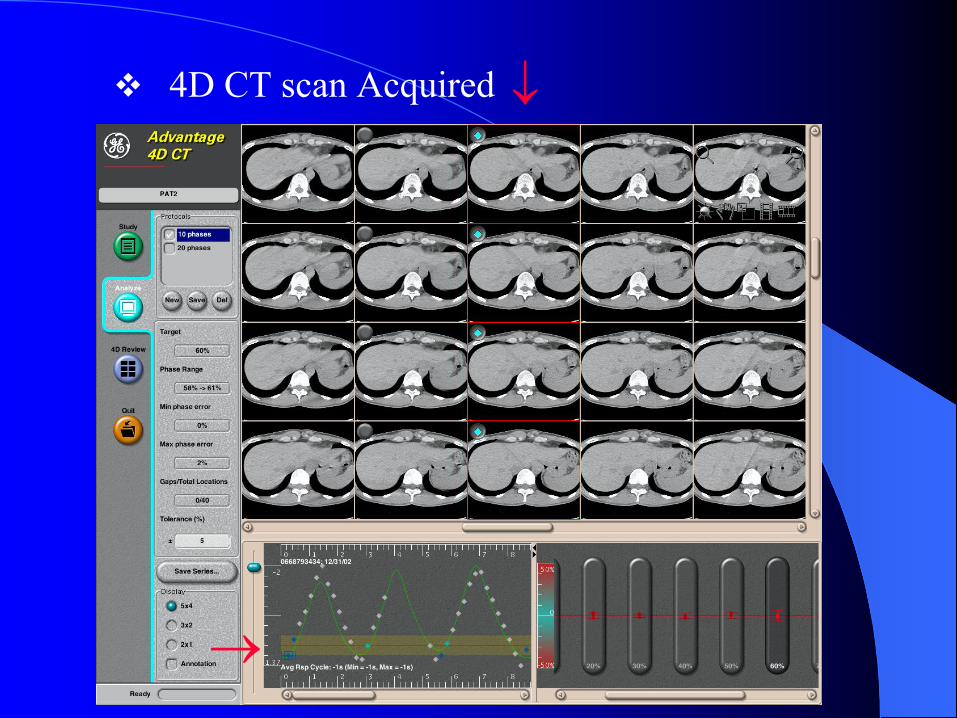
4D CT scan Acquired
→
↓
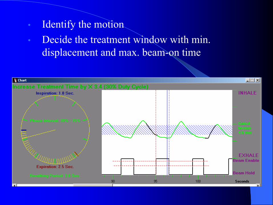
• Identify the motion • Decide the treatment window with min.
displacement and max. beam-on time
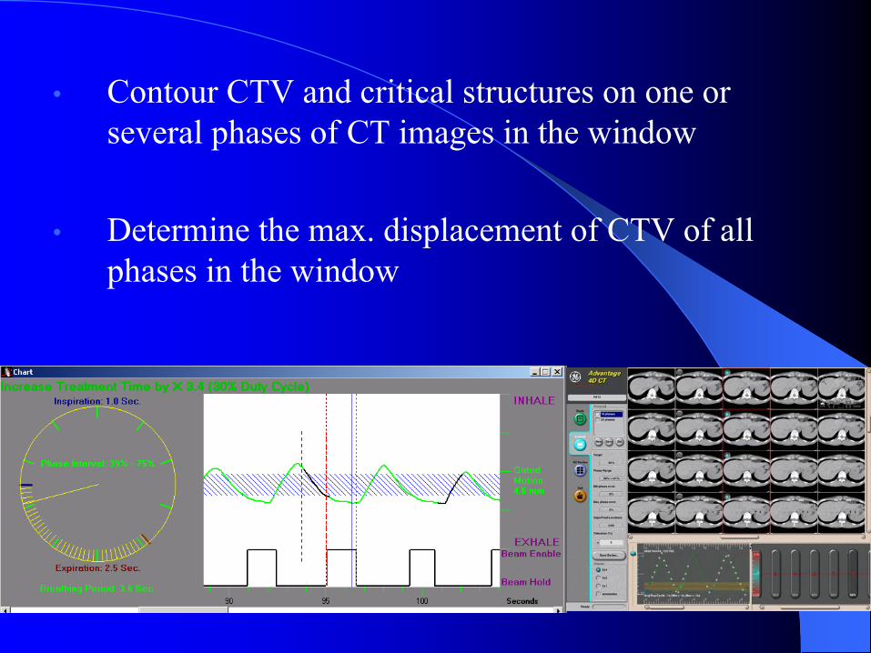
• Contour CTV and critical structures on one or several phases of CT images in the window
• Determine the max. displacement of CTV of all phases in the window
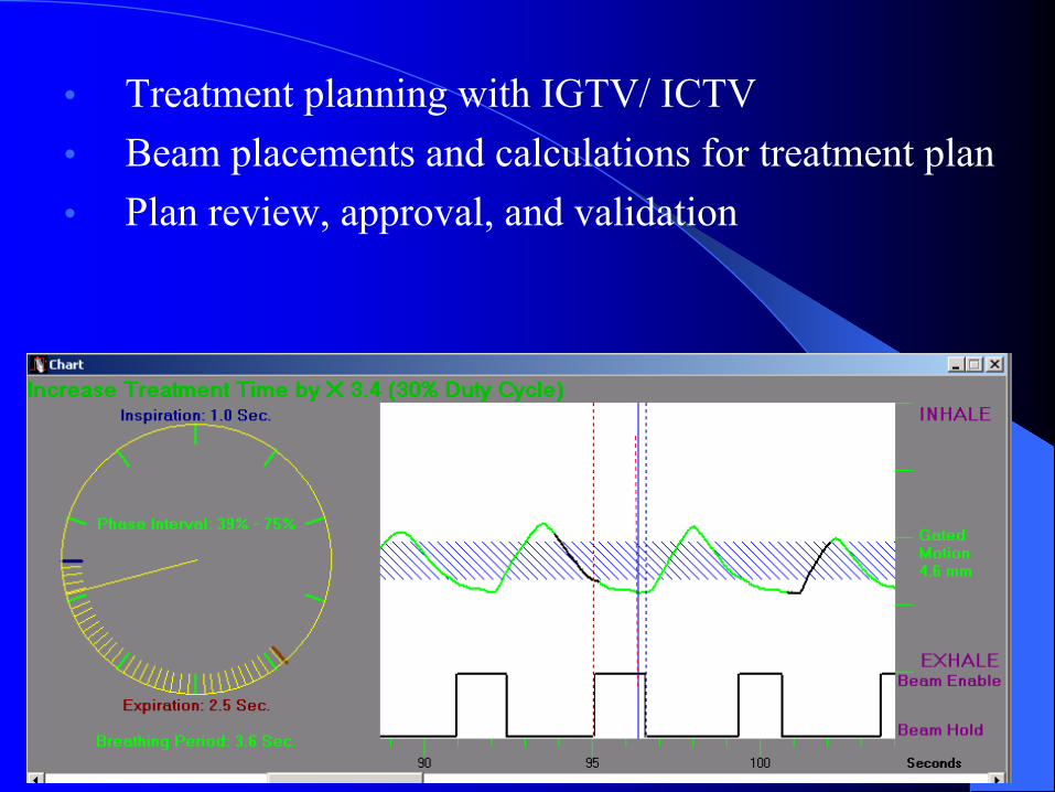
• Treatment planning with IGTV/ ICTV• Beam placements and calculations for treatment plan• Plan review, approval, and validation
4D CT planning4D CT planning
The explicit inclusion of temporal effects in radiotherapy treatment planning is referred to as 4D treatment planning
Intrafrational motion can be included in treatment planning at different levels
4D CT planning4D CT planningSimplest solution:– To generate a composite target volume that
encompass the CTV throughout organ motion during the respiratory cycle
Advanced:– Multiple dose calculations & deformable
registration

Targets DelineationTargets Delineation
With the 4D CT dataset, we can design the internal gross target volume (IGTV), that is the volume containing the GTV throughout its motion during respiration
One method of combining the data from the multiple CT datasets is to create a maximal intensity projection, which can be used as an aid in contouring the IGTV
MIP and Average CTMIP and Average CT
The MIP (or MIV) is a 3D CT dataset created by assigning each voxel the value of the highest value voxel at that location across the breathing phases
The average CT is a 3D CT dataset created by performing a voxel-by-voxel numerical averaging over all the breathing phases
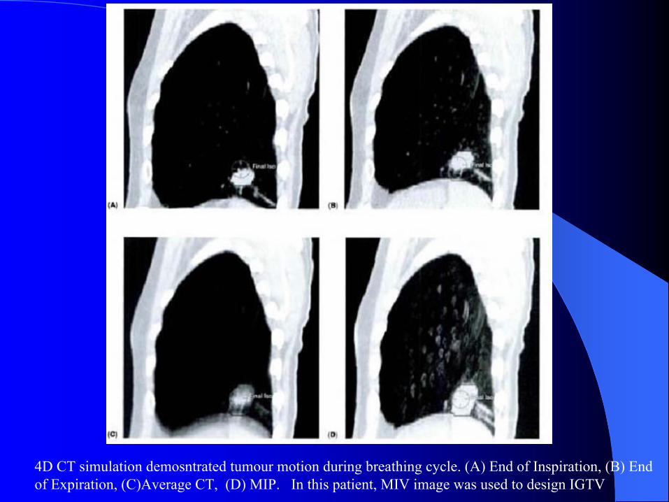
4D CT simulation demosntrated tumour motion during breathing cycle. (A) End of Inspiration, (B) End of Expiration, (C)Average CT, (D) MIP. In this patient, MIV image was used to design IGTV
Targets DelineationTargets Delineation
Another approach is to contour the GTV with the end of inspiration and expiration breath-holding and then combine these two volumes to form the IGTV – this approach can be used with regular spiral CT without 4D
All CT databases are transferred to the treatment-planning system for reference.
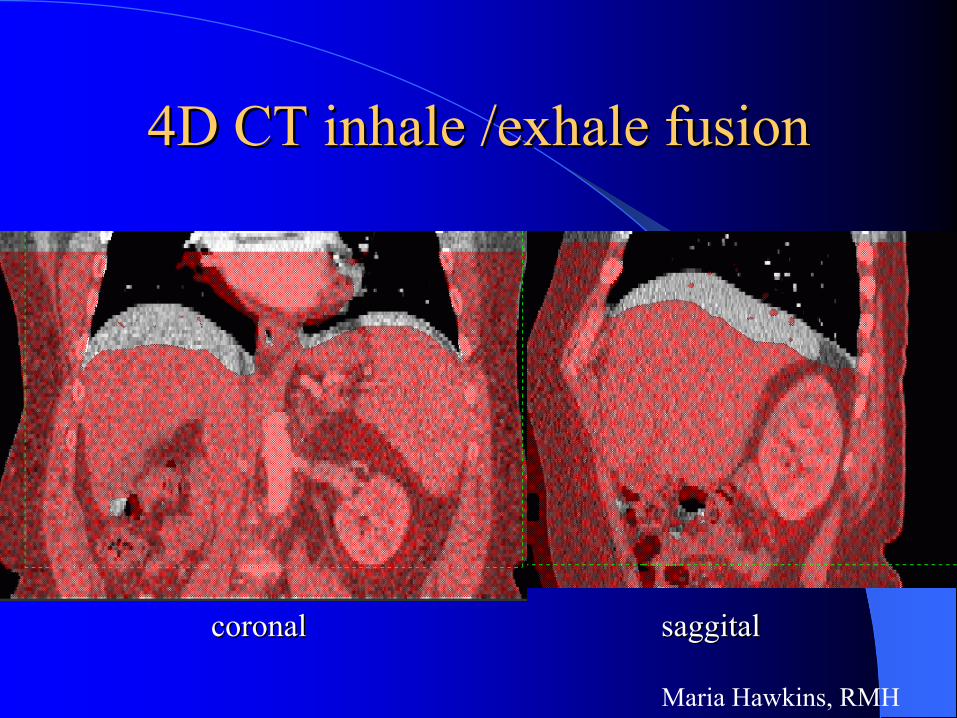
4D CT inhale /exhale fusion4D CT inhale /exhale fusion
coronalcoronal saggitalsaggital
Maria Hawkins, RMH

Treatment Planning Treatment Planning
All 10 respiratory-phase datasets, the MIP, and the average CT along with extended range free-breathing CT acquired during the same imaging session are transferred to the treatment planning system
The information is crucial for target delineating using the internal taget volume (ITV) approach to take tumour motion into consideration
4D 4D vsvs 3D Target Volumes3D Target Volumes
4D target volumes differ from those derived from conventional helical scanning
Differences: the shapes of volumes of interest and their centroids change – more accurate from 4D CT
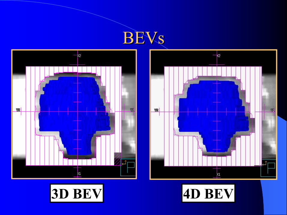
3D BEV 4D BEV
BEVsBEVs
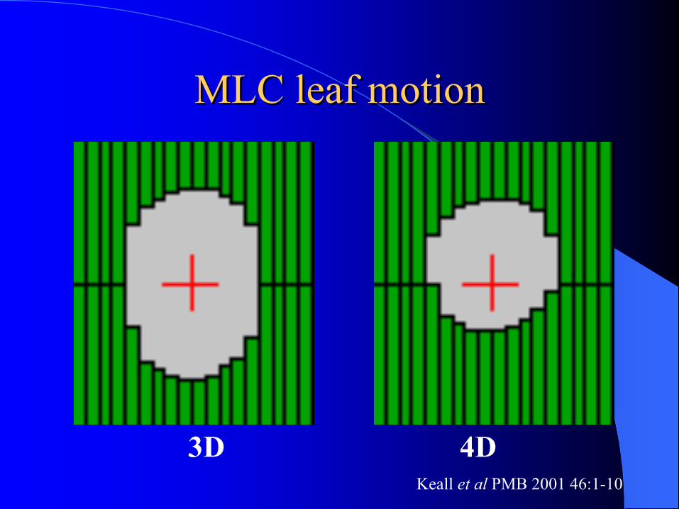
MLC leaf motion MLC leaf motion
3D 4DKeall et al PMB 2001 46:1-10
Image RegistrationImage RegistrationAnother approach is to use a deformable registration technique in which the tumour volume outlined on the expiratory phase of the 4D images is registered on other phases of the images to create a union of target contours, enclosing all possible positions of the target– Mathematically, this is to find the transformation matrix, that maps
an arbitrary point from the fixed image to the corresponding point on the floating image (or vice versa)
– e.g. using a freeware tool vtkCISG (Hartkens et al 2002)
The resulting IGTV contour is then evaluated across all phases
Treatment Planning with Image Treatment Planning with Image RegistrationRegistration
A treatment plan was created on the end-exhale CT image set and then automatically created on each of the 3D CT image sets corresponding with subsequent respiration phases, based on the beam arrangement and dose prescription in the end-exhale plan.Dose calculation using e.g. Monte Carlo, is simultaneously performed on each of the 3D image sets
Treatment PlanningTreatment Planning
The dose distribution from each respiratory phase CT image set was mapped back to the end-exhale CT image set for analysis
– 4D dataset therefore provides the ability to study the impact of respiratory motion on dose distribution
– The use of deformable image registration to merge all the statistically noisy dose distributions back onto one CT image set effectively yields a 4D Monte Carlo calculation with a statistical uncertainty equivalent to a 3D calculation
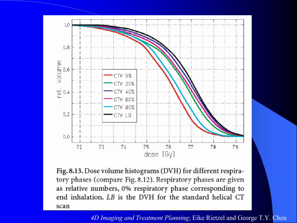
4D Imaging and Treatment Planning; Eike Rietzel and George T.Y. Chen

3D (solid) vs 4D (dashed) DVHs3D (solid) vs 4D (dashed) DVHs
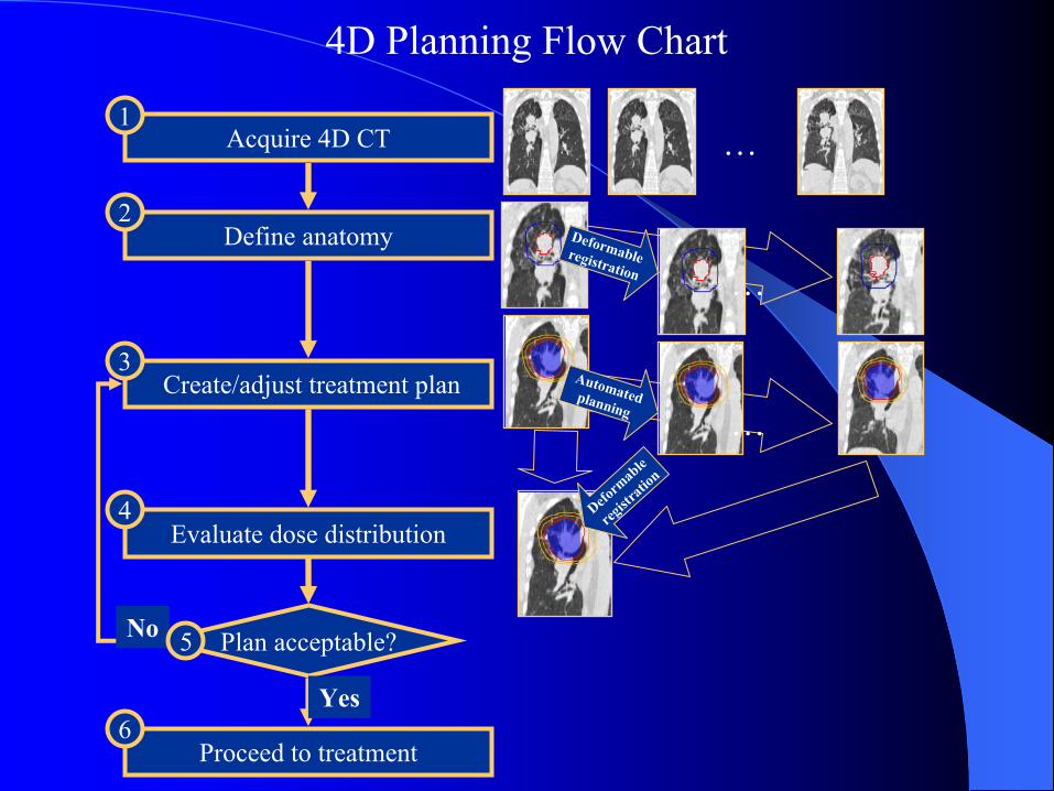
Acquire 4D CT
Define anatomy
Create/adjust treatment plan
Evaluate dose distribution
1
4
3
2
Proceed to treatment6
…
Plan acceptable?No
Yes
Deformable registration …
Automatedplanning …
Deform
able
regist
ration
5
4D Planning Flow Chart
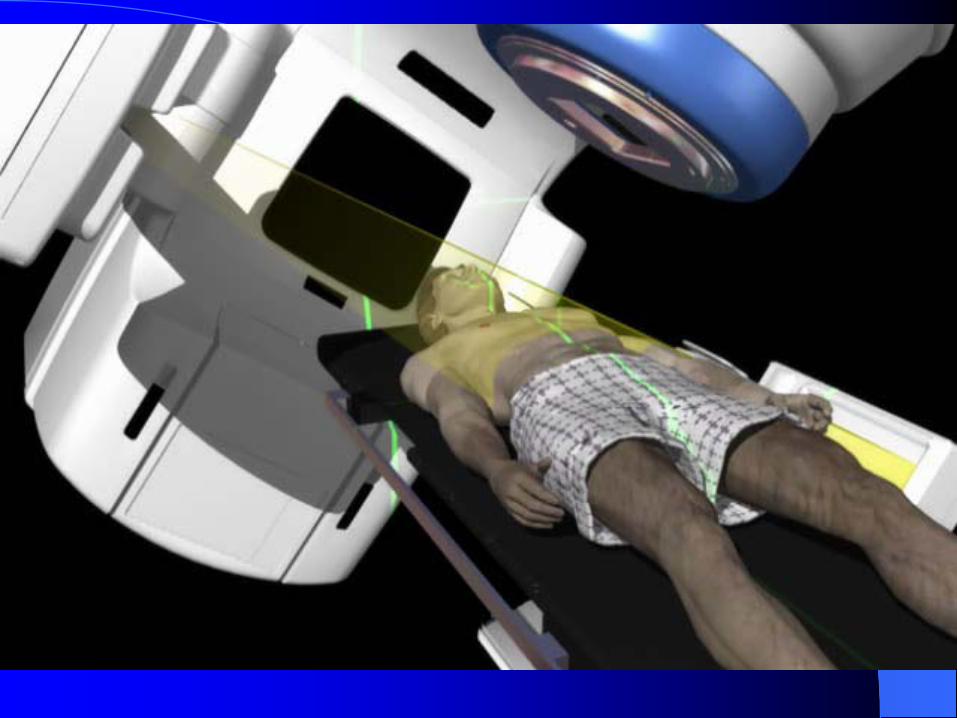
Treatment deliveryTreatment delivery
• Treatment delivered to the planned volume
• Treatment can be delivered with a gated beam control
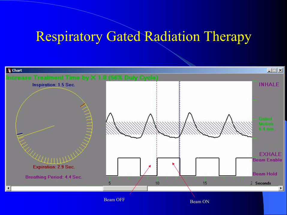
Beam ONBeam ONBeam OFFBeam OFF
Respiratory Gated Radiation Therapy
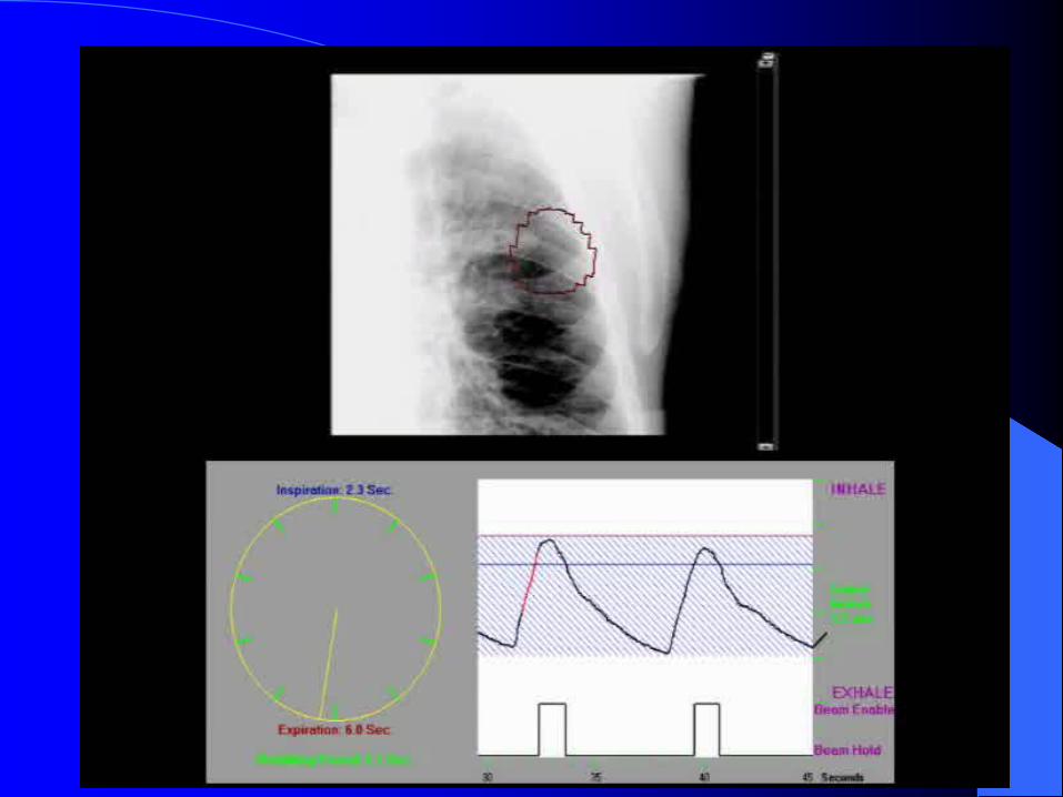
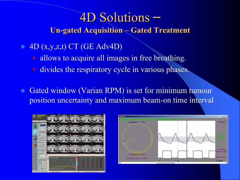
4D Solutions 4D Solutions ––UnUn--gated Acquisition gated Acquisition –– Gated TreatmentGated Treatment
4D (x,y,z,t) CT (GE Adv4D) allows to acquire all images in free breathing. divides the respiratory cycle in various phases.
Gated window (Varian RPM) is set for minimum tumourposition uncertainty and maximum beam-on time interval
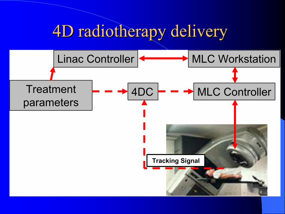
4D radiotherapy delivery4D radiotherapy deliveryLinac Controller MLC Workstation
MLC Controller4DC
Tracking Signal
Treatment parameters
Linac Controller MLC Workstation
MLC Controller4DC
Tracking Signal
Treatment parameters
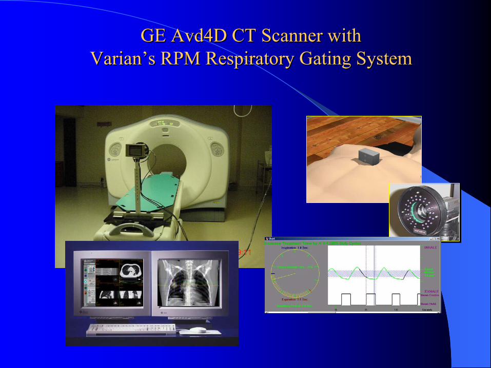
GE Avd4D CT Scanner with GE Avd4D CT Scanner with VarianVarian’’s RPM Respiratory Gating Systems RPM Respiratory Gating System

Gated IMRT for LungGated IMRT for Lung
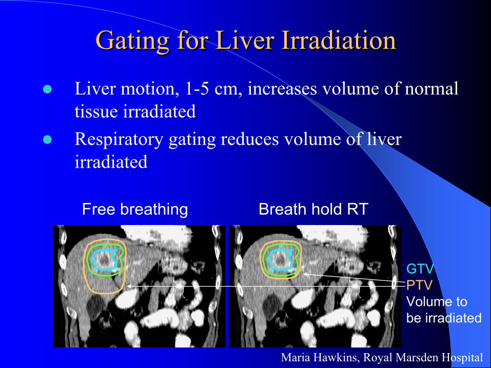
Maria Hawkins, Royal Marsden Hospital
Gating for Liver IrradiationGating for Liver Irradiation
Liver motion, 1-5 cm, increases volume of normal tissue irradiated Respiratory gating reduces volume of liver irradiated
GTVPTVVolume to be irradiated
Free breathing Breath hold RT
What is The Next Exciting New Dimension in IGRT ?
4D PET/CT4D PET/CT

Impact of PET/CT on Therapy PlanningImpact of PET/CT on Therapy Planning
PET/CT helps to find unsuspected involvement in the mediastinum
Can PET/CT help to re-define the treatment volume of a primary tumour ???
Images courtesy of Community Cancer Center, FL
CT PET PET/CT Fusion
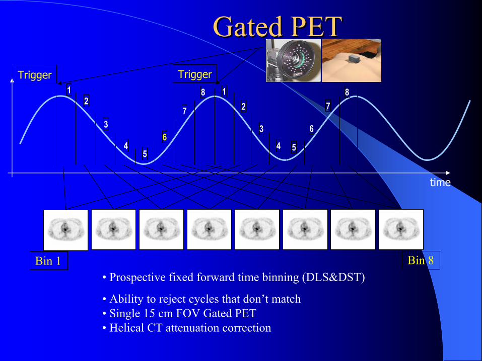
Gated PET Gated PET
time
7
3
4 5
6
8
3
45
6
7
Bin 8
82
Trigger1
Bin 1
21
Trigger
• Prospective fixed forward time binning (DLS&DST)
• Ability to reject cycles that don’t match• Single 15 cm FOV Gated PET• Helical CT attenuation correction
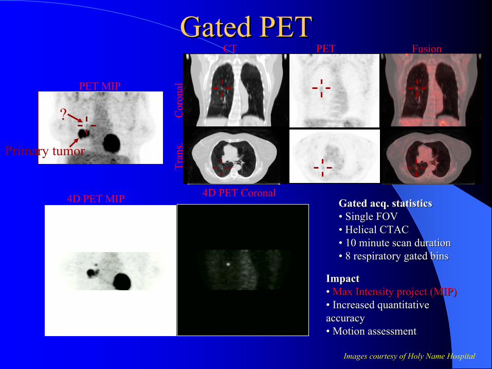
Gated PETGated PET
Images courtesy of Holy Name Hospital
PET MIP
4D PET MIP
Primary tumor
?
CT PET Fusion
Tran
s.
C
oron
al4D PET Coronal
Gated Gated acqacq. statistics. statistics•• Single FOVSingle FOV•• Helical CTACHelical CTAC•• 10 minute scan duration10 minute scan duration•• 8 respiratory gated bins8 respiratory gated bins
ImpactImpact•• Max Intensity project (MIP)Max Intensity project (MIP)•• Increased quantitative Increased quantitative accuracyaccuracy•• Motion assessmentMotion assessment
4D Radiotherapy: Caveats4D Radiotherapy: CaveatsOther variables exist:– Cardiac motion– Interfractional motion – set up errors, variations in
physiologic state (e.g. stomach size)
The data acquired in 4D CT is synthesized from multiple breaths during an acquisition time of a few minutes– Reproducitiliby of this pattern during each treatment
fraction is implicitly assumed when analyzing these resulting 4D dose distributions
– Possible variations may be monitored by examining the respiratory trace on a daily basis
4D Radiotherapy: Looking Ahead4D Radiotherapy: Looking AheadTechniques to deliver 4D treatment is still being developed and refined to take full advantage of the knowledge provided by 4D CT
Image guided therapy in the treatment room could well include 4D cone beam CT, if appropriate
The aim is to mitigate the dose-perturbing effects of motion, and possibly lead to safe decrease of geometric margins and increased therapeutic gain
Incorporation of functional imaging informations
Respiratory motion causes problems during the imaging, planning and treatment stages of radiotherapySeveral methods have been proposed to address respiratory motion:
1) Target positioning2) Robotic tracking3) Real-time monitoring4) 4D planning & gating
4D radiotherapy has some advantages over existing methodsThere are still many unanswered questions …
ConclusionsConclusions
AcknowlegementAcknowlegement
I am indebted to Professor Andrew Wu, PhD, of Department of Radiologic Sciences,Thomas Jefferson University, Philadelphia, Pennsylvania, Varian, Elekta and Siemens for lending me slides & videos for this talk.

Thank You !Thank You !