490b report
TRANSCRIPT
1
Usage of a Hexacopter Platform for ChemicalPlume Detection and Photography
Miles Heaton; CSU Bakersfield Robotics Lab
Abstract—This report outlines the steps taken to con-figure and adapt a DJI F550 hexacopter from a DIY dronekit for hobby purposes into a mobile sensor platformwhich can both detect a chemical plume and completeany necessary maneuver to locate the source. In orderto do this, the drone has to built and configured tofly autonomously, a sensor platform needs to be built,and testing needs to be done to determine if the partswork together well. Two drones were built, one using anArduPilot Mega 2.5 flight controller and the other usinga Pixhawk flight controller, both of which are producedby 3DRobotics. The different flight controller units bothrequired the same steps to build and configure.
I. OBJECTIVE
To adapt a hexacopter drone into a platform which canbe used to locate the source of a chemical plume and tophotograph the location.
II. PROCEDURE
Over the course of building and flying the drones, anumber of steps had to be accomplished to completethe project: the drones needed to be built; the flightcontrollers needed to be configured and connected to theadditional parts; the drones needed to be flown to ensurethey were put together correctly and determine if the GPSmodules worked; stands were built for two drones sothat testing could be done inside of a laboratory insteadof going outside for one short test; an acrylic scaffoldwas added above the battery on one drone to house thechemical sensors; Python scripts were coded to control adrone; and a GoPro Hero 3+ Silver camera was attachedto a drone using a Tarot T-2D brushless gimbal.
III. BUILDING AND CONFIGURING THE TWO DRONES
As two flight controllers were used, two drones werebuilt. The steps for building and flying each are identical,with the only differences being that the ArduPilot Mega2.5 flight controller is based off of the Arduino Megamicroprocessor, and the Pixhawk flight controller is basedoff of the ARM microprocessor.
A. Building the DJI Flame Wheel F550 drone kit
Due to the kit being almost ready-to-fly, most of theparts are easily screwed together. The kit consists of:two ground plates, one top plate and one bottom plate; sixarms, one for each rotor; six electronic speed controllers,
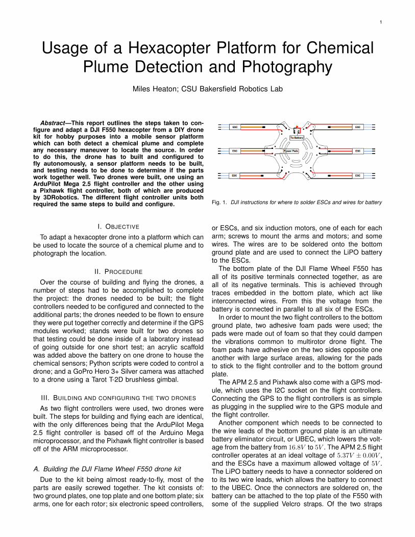
Fig. 1. DJI instructions for where to solder ESCs and wires for battery
or ESCs, and six induction motors, one of each for eacharm; screws to mount the arms and motors; and somewires. The wires are to be soldered onto the bottomground plate and are used to connect the LiPO batteryto the ESCs.
The bottom plate of the DJI Flame Wheel F550 hasall of its positive terminals connected together, as areall of its negative terminals. This is achieved throughtraces embedded in the bottom plate, which act likeinterconnected wires. From this the voltage from thebattery is connected in parallel to all six of the ESCs.
In order to mount the two flight controllers to the bottomground plate, two adhesive foam pads were used; thepads were made out of foam so that they could dampenthe vibrations common to multirotor drone flight. Thefoam pads have adhesive on the two sides opposite oneanother with large surface areas, allowing for the padsto stick to the flight controller and to the bottom groundplate.
The APM 2.5 and Pixhawk also come with a GPS mod-ule, which uses the I2C socket on the flight controllers.Connecting the GPS to the flight controllers is as simpleas plugging in the supplied wire to the GPS module andthe flight controller.
Another component which needs to be connected tothe wire leads of the bottom ground plate is an ultimatebattery eliminator circuit, or UBEC, which lowers the volt-age from the battery from 16.8V to 5V . The APM 2.5 flightcontroller operates at an ideal voltage of 5.37V ± 0.00V ,and the ESCs have a maximum allowed voltage of 5V .The LiPO battery needs to have a connector soldered onto its two wire leads, which allows the battery to connectto the UBEC. Once the connectors are soldered on, thebattery can be attached to the top plate of the F550 withsome of the supplied Velcro straps. Of the two straps
2
Fig. 2. 3DRobotics ArduPilot Mega 2.5 flight controller
Fig. 3. 3DRobotics Pixhawk flight controller
Fig. 4. GPS module for the 3DR ArduPilot Mega 2.5
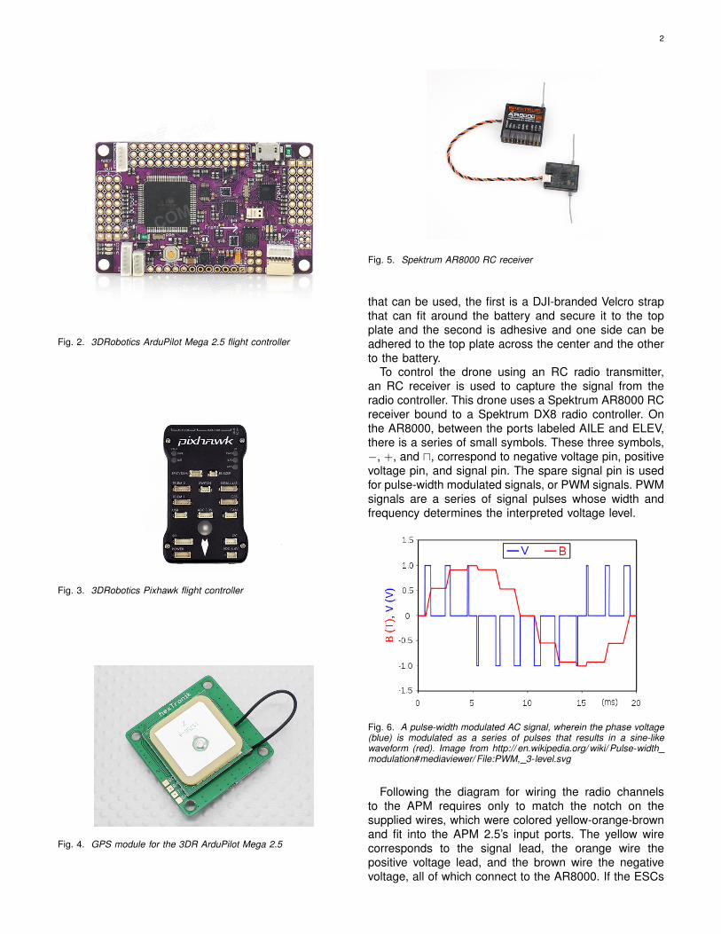
Fig. 5. Spektrum AR8000 RC receiver
that can be used, the first is a DJI-branded Velcro strapthat can fit around the battery and secure it to the topplate and the second is adhesive and one side can beadhered to the top plate across the center and the otherto the battery.
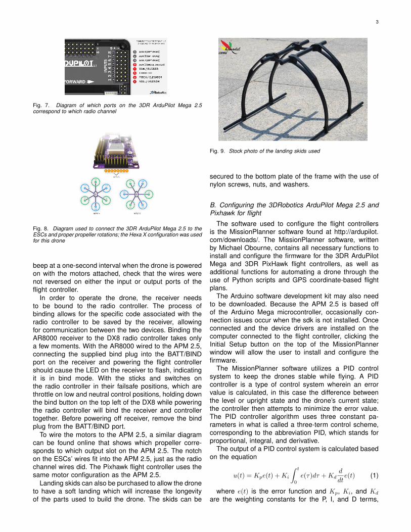
To control the drone using an RC radio transmitter,an RC receiver is used to capture the signal from theradio controller. This drone uses a Spektrum AR8000 RCreceiver bound to a Spektrum DX8 radio controller. Onthe AR8000, between the ports labeled AILE and ELEV,there is a series of small symbols. These three symbols,−, +, and u, correspond to negative voltage pin, positivevoltage pin, and signal pin. The spare signal pin is usedfor pulse-width modulated signals, or PWM signals. PWMsignals are a series of signal pulses whose width andfrequency determines the interpreted voltage level.
Fig. 6. A pulse-width modulated AC signal, wherein the phase voltage(blue) is modulated as a series of pulses that results in a sine-likewaveform (red). Image from http:// en.wikipedia.org/ wiki/ Pulse-widthmodulation#mediaviewer/ File:PWM, 3-level.svg
Following the diagram for wiring the radio channelsto the APM requires only to match the notch on thesupplied wires, which were colored yellow-orange-brownand fit into the APM 2.5’s input ports. The yellow wirecorresponds to the signal lead, the orange wire thepositive voltage lead, and the brown wire the negativevoltage, all of which connect to the AR8000. If the ESCs
3
Fig. 7. Diagram of which ports on the 3DR ArduPilot Mega 2.5correspond to which radio channel
Fig. 8. Diagram used to connect the 3DR ArduPilot Mega 2.5 to theESCs and proper propeller rotations; the Hexa X configuration was usedfor this drone
beep at a one-second interval when the drone is poweredon with the motors attached, check that the wires werenot reversed on either the input or output ports of theflight controller.
In order to operate the drone, the receiver needsto be bound to the radio controller. The process ofbinding allows for the specific code associated with theradio controller to be saved by the receiver, allowingfor communication between the two devices. Binding theAR8000 receiver to the DX8 radio controller takes onlya few moments. With the AR8000 wired to the APM 2.5,connecting the supplied bind plug into the BATT/BINDport on the receiver and powering the flight controllershould cause the LED on the receiver to flash, indicatingit is in bind mode. With the sticks and switches onthe radio controller in their failsafe positions, which arethrottle on low and neutral control positions, holding downthe bind button on the top left of the DX8 while poweringthe radio controller will bind the receiver and controllertogether. Before powering off receiver, remove the bindplug from the BATT/BIND port.
To wire the motors to the APM 2.5, a similar diagramcan be found online that shows which propeller corre-sponds to which output slot on the APM 2.5. The notchon the ESCs’ wires fit into the APM 2.5, just as the radiochannel wires did. The Pixhawk flight controller uses thesame motor configuration as the APM 2.5.
Landing skids can also be purchased to allow the droneto have a soft landing which will increase the longevityof the parts used to build the drone. The skids can be
Fig. 9. Stock photo of the landing skids used
secured to the bottom plate of the frame with the use ofnylon screws, nuts, and washers.
B. Configuring the 3DRobotics ArduPilot Mega 2.5 andPixhawk for flight
The software used to configure the flight controllersis the MissionPlanner software found at http://ardupilot.com/downloads/. The MissionPlanner software, writtenby Michael Obourne, contains all necessary functions toinstall and configure the firmware for the 3DR ArduPilotMega and 3DR PixHawk flight controllers, as well asadditional functions for automating a drone through theuse of Python scripts and GPS coordinate-based flightplans.
The Arduino software development kit may also needto be downloaded. Because the APM 2.5 is based offof the Arduino Mega microcontroller, occasionally con-nection issues occur when the sdk is not installed. Onceconnected and the device drivers are installed on thecomputer connected to the flight controller, clicking theInitial Setup button on the top of the MissionPlannerwindow will allow the user to install and configure thefirmware.
The MissionPlanner software utilizes a PID controlsystem to keep the drones stable while flying. A PIDcontroller is a type of control system wherein an errorvalue is calculated, in this case the difference betweenthe level or upright state and the drone’s current state;the controller then attempts to minimize the error value.The PID controller algorithm uses three constant pa-rameters in what is called a three-term control scheme,corresponding to the abbreviation PID, which stands forproportional, integral, and derivative.
The output of a PID control system is calculated basedon the equation
u(t) = Kpe(t) +Ki
∫ t
0
e(τ)dτ +Kdd
dte(t) (1)
where e(t) is the error function and Kp, Ki, and Kd
are the weighting constants for the P, I, and D terms,

4
Fig. 10. Frame selection options in the MissionPlanner setup
respectively. By computing a weighted sum of the errorvalues, the process in question can be adjusted. In thecase of the drones, each rotational axis has its own PIDcontroller to determine how much power needs to be putinto the motors to level out the drone.
1) Installation of MissionPlanner: The aforementionedurl links to the most recent version of the MissionPlannersoftware. A simple download and install is all that isneeded.
2) Installing the firmware: To install the firmware forthe APM 2.5 and PixHawk flight controllers is simple andeasy. First the flight controller needs to be connected tothe computer through the use of a male USB-to-malemicroUSB cable.
The initial setup of the firmware can take some time,and contains only a few steps.
a) Frame type: The first step to set up the firmwarerequires the selection of the proper frame type of thedrone in question. The frame type of the drone is deter-mined by the number of motors, which shape the droneis, and where the center of the drone and its front are. Asthe DJI Flamewheel F550 has six motors equally spacedalong one plane with the front being located between twoof the drone’s arms, it uses the ’hexa 6X’ frame type,with the necessary selection being the ’X’ and ’Y6A’ typeselection for this drone.
When first connecting the flight control to the Mission-Planner software, it was noticed that the hexa 6x frametype isn’t selectable. By configuring the firmware throughthe wizard option, the ’X’ and ’Y6A’ option is selectable,allowing for the proper frame type to be used.
b) Accelerometer calibration: Accelerometers aresensors which detect motion. They are most commonlyfound in smart phones to detect if the phone has beentilted or is laying flat. In this drone, with the sensor specifi-cally located in the flight controller unit, the accelerometeris used for stabilizing flight, which is achieved mainlythrough detecting the amount of tilt and in which direction.Calibrating the accelerometer requires placing the droneon a flat surface and then setting the drone on different
sides to simulate those motions for the accelerometer ina controlled environment. After having the drone lay flatit must be placed with its front down, the on its left andright sides, and then on its back side. Once its sides areplaced down it is to be placed with its top side down.
c) Magnetometer calibration: A magnetometer,commonly called a compass, detects the direction whichthe drone is facing with respect to the Earth’s magneticfield. In order to calibrate the magnetometer on theAPM 2.5, the flight controller needs to be rotated untilthe software has a sufficient amount of points to knowwhich direction is which. Numerous calibration attemptshave needed vastly different amounts of points for asufficient data set, with the least necessary in one trialbeing ≈ 400 and the largest being ≈ 1300. The commondirections for calibrating a magnetometer are to face thefront of the flight controller north and then rotating ineach direction 360◦, which often are all that is needed,but in some tests were not enough and spinning theflight controller around a number of times more werenecessary for the MissionPlanner to display that themagnetometer has been calibrated.
d) RC radio calibration: The calibrations for the radiocontroller require the two joysticks on the radio controllerto be moved into positions from their lowest positionto their highest, along with whichever auxiliary switchesare used. This step is easily the simplest, and shouldtake no more than a few minutes. By completing thisstep, the maximum and minimum PWM values of theradio controller are found and are used for arming anddisarming the motors, along with flight.
C. Installing the 3DRobotics telemetry radios
An additional, and often recommended purchase is apair of 3DRobotics (3DR) telemetry radios. By settingup the radios information from the drone such as GPSposition and air speed can be wirelessly transmitted tothe ground station, which in this setup is the laptop usedfor tuning the flight controller.
Fig. 11. Stock photo of a 3DRobotics telemetry radio
In order to configure the radios for wireless communi-cation between the ground station laptop and hexacopter,
5
Fig. 12. Settings for the 3DRobotics telemetry radios
Fig. 13. Sketch of the radio controller with labeled joysticks and toggleswitch for flight modes
a few settings need to be changed in the MissionPlannersoftware’s ”3DR radios” menu selction under the ’OptionalHardware’ dropdown in the INITIAL SETUP tab.
The ECC parameter, which is used for error correction,is deselected for the reason that using ECC halves theavailable data bandwidth. This is unnecessary for mostcases as the drone is flying close enough to the groundstation that a link between radios is very easily sustained.The MAVLink option allows for MAVLink framing, whichaligns radio packets with MAVLink packet boundaries.This way if a data packet is lost a fragmented packetis disregarded by the radio and appears as noise. Opresend, or opportunistic resend, is an option which canresend a packet if there is no other outgoing operationbeing sent through the radio. Because data will always bereceived through the local radio connected to the groundstation, it is unnecessary to enable op resend.
Before attempting to fly the drone, steps must be takenin regard to safety to avoid any injury. These propellersspin at an incredibly high speed, with a maximum of ≈15450RPM . Care must be taken to never be near thedrone when its motors are armed, and to always keepthe motors disarmed when not in use.
There are three methods of control for flying the drone:using manual control, using GPS coordinate system way-points, and using Python scripts.
D. Manual flight
On the RC controller, there are two joysticks capable ofanalog two dimensional motion. On the left joystick, the
vertical axis is used for the throttle and the horizontal axisis used for the roll. On the right joystick, the vertical axisis used for the pitch and the horizontal axis is used for theyaw. These four degrees of motion are used to control thedrone. Throttle is used to increase or decrease the speedof the motors which allow for increasing or decreasing thespeed at which the drone gains or loses altitude. Roll isused for horizontal rotation of the drone, which allows forspinning in circles. Pitch is used for forward and backwardrotation, which allows the drone to move in a forwardor backward direction. Yaw is used in the side-to-siderotation of the drone, which allows it to fly to the left andright.
Practicing manual control of the drone took the form ofa few exercises which allows the user to get an idea ofhow the drone operates. These exercises start by havingthe drone to lift off and land, and incrementally increasein difficulty to having the drone lift off and fly in a squarepattern before landing where it began.
E. GPS coordinate-based flight planningAfter spending time becoming comfortable with man-
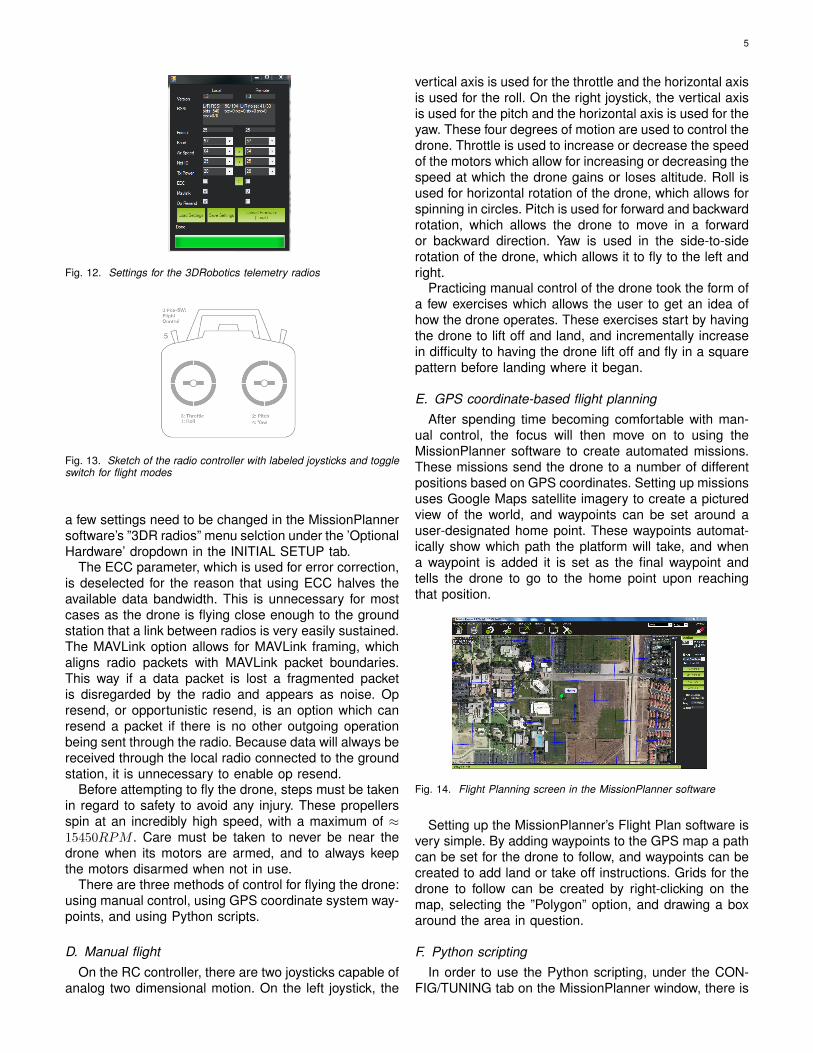
ual control, the focus will then move on to using theMissionPlanner software to create automated missions.These missions send the drone to a number of differentpositions based on GPS coordinates. Setting up missionsuses Google Maps satellite imagery to create a picturedview of the world, and waypoints can be set around auser-designated home point. These waypoints automat-ically show which path the platform will take, and whena waypoint is added it is set as the final waypoint andtells the drone to go to the home point upon reachingthat position.
Fig. 14. Flight Planning screen in the MissionPlanner software
Setting up the MissionPlanner’s Flight Plan software isvery simple. By adding waypoints to the GPS map a pathcan be set for the drone to follow, and waypoints can becreated to add land or take off instructions. Grids for thedrone to follow can be created by right-clicking on themap, selecting the ”Polygon” option, and drawing a boxaround the area in question.
F. Python scriptingIn order to use the Python scripting, under the CON-
FIG/TUNING tab on the MissionPlanner window, there is

6
Fig. 15. PID values for the ArduPilot Mega 2.5 flight controller.
an option for ’Standard Params’. At the top of the param-eter list there is a checkbox for ”Advanced Menu View”.Selecting this will allow for far more options to configureand tune the drone, and for adding additional optionsto the list on the Flight Data tab. One such additionaloption is ”Scripts”, which contains the necessary toolsfor loading and running Python scripts. In order to findthe ”Scripts” option, it maybe necessary to scroll the listto the right.
Once the stands were built, the drones were then usedto test how well Python scripting works. The MissionPlan-ner software was used to upload scripts into the PixHawkflight controller, and used a derivative of the IronPythonimplementation of the Python programming language.MissionPlanner uses two drone-specific libraries, whichare cs and Script. cs stands for current state, and cor-responds to any status variable of the drone; Script isa multifunction library which contains sleep and waitfunctions, as well as the function which sends an RCsignal to the drone.
#send integer PWM value pwm with range1000-2000 to RC channel chan, using boolsendnow as the trigger for sending
Script.SendRC(chan,pwm,sendnow)
This SendRC function is the most important, and mostused, function of these scripts, and it allows the Pythonscript to emulate an RC transmitter, thus allowing forthe full capabilities of flying the drone manually to beautomated. However, emulation does come at the cost oflosing any semblance of feedback, rendering the droneincapable of correcting for errors at this point in time;with smart algorithms and additional sensors the droneis certainly capable complex maneuvers.
The Python scripts were mainly used for determiningthe feasibility of automating the platform, and performedadmirably. After checking that the drone can overcomethe weight of the mount, the drones were then testedto see their effect on the gyroscope with various PIDvalues and how well each channel responds to above-and below-center PWM inputs, with a PWM value of 1500being the center or median value.
IV. PREPARING THE ARDUPILOT MEGA 2.5-EQUIPPEDDRONE FOR CHEMICAL PLUME TRACING
Because the APM 2.5 is based off of the Arduino Megamicroprocessor, it is capable of a multitude of options ina far simpler fashion than the Pixhawk. For this reasonthe chemical sensors were tested with the APM 2.5.
A. Building stands for indoor testing
Building the stands and mounts required a few partsand quite a bit of construction knowledge. Each standwas assembled using two 1
3” steel pipes, one sheet of116”-thick steel cut into a 2”x5” piece, a swivel adapterwhich fits 1
2” pipe, and a female-to-female 12” coupling.
One pipe was cut off one inch above the threads using achop saw so that the smaller piece could be welded ontothe piece of sheet metal. The small piece is cut one inchabove the threads so that the weight of the pipe doesn’tprevent the drone from taking off and stabilizing duringtesting.
Fig. 16. Threaded steel pipe, cut into an approximately 1 12”-long piece.
Fig. 17. Steel sheet with screw holes drilled using 18”, 1
4”, and 3
8” drill
bits; a unibit step drill bit was used to clean up any sharp edges.
Before welding, the threaded piece was fitted with acap and then covered in painter’s tape. This preventedany splatter from sticking to the threads of the pipe, butdid come with the danger of the tape catching on fire.

7
Fig. 18. Drone mount just before welding.
Anti-splatter spray could be used for a similar purpose,but none was on hand at the time of welding. Wire-feedand stick welding machines were both used and are bothviable; the only reason both were used was based onwhichever was available at the time.
After welding the mount together, some cleanup wasrequired. A grinder was used to clean off the splattersfrom the sheet metal and a few from the pipe. The pipeonly had some splatters taken off because others weretoo close to the threads to allow removal. A wire brushwas then taken to the mount to remove some of thediscoloration caused by welding with a galvanize coatingand to smooth over the areas affected by the grinder.The swivel adapter was attached to the remaining steelpipe by use of the coupling, and then placed in the wiremanagement hole of a desk in the lab and tied down.
Each mount was attached to the drone by use ofhanger tape, wing nuts, and thumb screws. The mountswere then screwed into the swivel adapters and wereready to test.
B. Sensor scaffold
A small platform was made out of acrylic to elevatethe chemical sensors from the propellers of the droneand provide a flat surface without relocating the batteryfor the drone. The platform was cut using a hand-heldrotary tool, and had 1
8” holes drilled in to fit 332” diameter
spacers, which were approximately 2” long. The holesdrilled corresponded to the point in between all four screwholes used to connect the top plate to the arms of thedrone. This way the platform was balanced along sixpoints, though due to the limited amount of parts on-handonly four stacks of two spacers were used to separate theplatform from the top plate of the drone.
V. ADAPTING THE PIXHAWK-EQUIPPED DRONE FORPHOTOGRAPHY
With readily-available guides being designed for thePixhawk, the drone with the Pixhawk was used for testingthe capabilities of the Tarot T-2D brushless gimbal with aGoPro Hero 3+ Silver camera.
Fig. 19. Completed drone, picture taken 20 November, 2014; top view.
Fig. 20. Connection guide for the Tarot T-2D brushless gimbal andPixhawk flight controller.
A. Building and configuring the Tarot gimbal
The Tarot T-2D brushless gimbal is a two-axis stabilizerfor a GoPro Hero 3 action camera. The gimbal requiresminimal construction, and much of the work needed wastuning and debugging. At first the gimbal acted erratically,and after some fact-checking it was found that the roll andtilt motor connectors were swapped during construction,and after exchanging the two connectors the gimbalfunctioned perfectly.
After building the gimbal, the configuration wizardcan be downloaded from the Tarot website. The file”ZY X−BMGC−EN V 1.5.exe” is the executable to loadthe wizard, and contains PID settings for both motors.The steps listed in the firmware read-me dictate thatfirst setting the accelerate gain to 100 and the velocityand integral gain to 0, and then increase the accelerategain until the motor begins to oscillate. This finds theaccelerate gain max, and the actual gain should be setto 80% of the max. Then the integral gain needs to beadjusted until the motor oscillates, and set to 80% of thatmax; the same is then to be done with the velocity gain.Once finished the same steps need to be repeated forthe second motor. Once done the gimbal is configuredand ready to be used.

8
However, after some testing the default PID values forboth motors worked as well as the tuned PID values.There may have been some differences, but were indis-cernible during the tests. It was also noted that the gimbalwould not balance correctly unless the GoPro camerawas attached to the gimbal, likely due to how the gimbalwas calibrated.
It is also possible for the DX8 controller to be able tocontrol the tilt motor on the gimbal. By connecting thegimbal to the Pixhawk or APM 2.5 flight controllers, thetilt motor can be controlled by using one of the normally-unused radio channels. To do this, the Tarot gimbal wasconnected to the Pixhawk flight controller by connectingthe AUX1 GND pin on the Pixhawk to the P- pin on theTarot gimbal and the AUX1 signal pin to the CT pin onthe Tarot gimbal. Then in the optional hardware sectionof MissionPlanner’s Initial Setup tab, the servo limits ofthe tilt motor need to be set to min 1000 and max 1520,the angle limits −90 and 0, and the Input Channel to anunused radio controller channel.
B. Installing and testing the GoPro Hero 3+ Silver actioncamera
The camera used for this drone was a GoPro Hero3+ Silver camera, which is a digital camera capable offilming a 1080p video at 60 frames per second. GoProcameras are common low-cost video cameras used forfirst-person views of various hobbies and sports. As theTarot gimbal is designed for GoPro cameras this was theobvious choice.
There are two ways of connecting to the GoPro tostream the camera feed. The first way is to connect tothe camera’s built-in wifi transmitter using a Windows PCand connecting to the camera’s live feed. This requiresthe use of a third party media player which has thecorresponding codecs to view network streams. VLCis the most commonly used media player for viewingnetwork streams, and was used with the GoPro. However,only versions 2.01 through 2.08 are confirmed to workcorrectly with GoPro Hero 3+ cameras, so version 2.08of the program was used.
To connect to the GoPro’s wifi, the wifi must first beturned on for both the PC and GoPro camera. On theright side of the camera, facing the back, there is a smallbutton. Pressing this button while the camera is on willturn on the wifi connectivity. If the camera is transmittinga wifi signal an led light on the front of the camera willflash blue one time each second. On the PC there willthen be an option to connect to an SSID that begins with”GOPRO-BP.” The default WEP key needed to connectto the camera, as detailed in the options, is ”goprohero”.
If done properly, connecting to http://10.5.5.9:8080/ inany PC browser will bring up the file list of the GoPro. InVLC, selecting ”Open Network Stream” under the Mediatoolbar and typing in http://10.5.5.9:8080/live/amba.m3u8will connect to the camera feed of the GoPro. There isa slight delay, ranging in tests from one to ten seconds,
Fig. 21. GoPro button, led, connector, and depression descriptions.
Fig. 22. GoPro descriptions, cont.
but averaging about three seconds. The settings on thecamera were changed from 1080p/60fps to 720p/30fps,and the quality of the camera feed and length of thedelay did not change; from this it was determined thatthe quality of the video does not have any effect on thedelay of the camera to PC.
Another way to view the camera feed is through theGoPro App for iOS and Android devices, through theApp Store or Google Play Store, respectively. The appsearches for a GoPro wifi signal and connects in a similarway as on a PC. The media playback is built-in to the appand has a delay comparable to that on a PC.
The GoPro App has the added benefits of being ableto control the camera wirelessly. This requires a microSDcard, which goes into the microSD card slot on thecamera. Any size microSD card can work, with the largersizes able to hold a larger number of photos or longervideos. The only necessity for the microSD card is thatit is a UHS Class 10 or higher SD card. The UHS speed
9
Fig. 23. Screenshot taken from the GoPro App for Android.
classes correspond to the write speed of the SD card inMb/s. Because the GoPro Hero 3+ Silver cameras canrecord at resolutions and framerates up to 1080p/60fpsrespectively, the speed class requirement is necessary. Itwas noted that going from 1080p/60fps to 720p/30fps ona 16GB SDHC microSD card from Sandisk added aboutone minute of video, going from 1:12 of possible time to2:12.
A simple test was performed at CSUB to determinethe range of the GoPro wifi signal. By connecting theGoPro to a laptop and leaving it at one end of a hallway,the delay was tested at different distances by makingan observable motion and checking the amount of timebefore the video feed displayed the motion; the rangestested went from 0m, testing the delay while the laptopand camera were next to each other, to ≈ 55m, at theend of the hallway in question. As the delay was constantthroughout, it was determined that the signal strength ishigh at up to 55m. Later it was found that tests have putthe wifi signal range of the GoPro at a maximum of 330m.
VI. RESULTS
The drone works very well, with the additional equip-ment requiring only additional thrust for takeoff. Afteradditional testing, it was concluded that while thesedrones as we’ve built may not be able to explicitly locatethe source of a chemical plume, it can map an areafor a chemical. The propellers do have an effect on thechemical sensors due to their placement, but the sen-sors did detect some of the ethanol used; their locationsuspended above the drone is acceptable insofar that thechemical in question does reach the sensors. The Pythonscripts may not be able to directly control the droneusing the data from the chemical sensors at this time,but the GPS missions and Python scripts can insteadbe used to create a grid for the sensors to collect dataover an area; thus allowing for a high concentration to
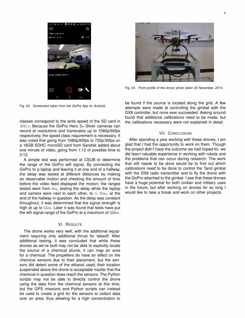
Fig. 24. Front profile of the drone; photo taken 20 November, 2014.
be found if the source is located along the grid. A fewattempts were made at controlling the gimbal with theDX8 controller, but none ever succeeded. Asking aroundfound that additional calibrations need to be made, butthe calibrations necessary were not explained in detail.
VII. CONCLUSION
After spending a year working with these drones, I amglad that I had the opportunity to work on them. Thoughthe project didn’t have the outcome we had hoped for, wedid learn valuable experience in working with robots andthe problems that can occur during research. The workthat still needs to be done would be to find out whichcalibrations need to be done to control the Tarot gimbalwith the DX8 radio transmitter and to fly the drone withthe GoPro attached to the gimbal. I see that these droneshave a huge potential for both civilian and military usesin the future, but after working on drones for so long Iwould like to take a break and work on other projects.

10
VIII. APPENDICES
A. Python Scripts
• Throttle test script; written by Miles Heaton:
#begin the script and find the minimum valuefor channel 3
print ’Start Script’for chan in range(1,9):
Script.SendRC(chan,1500,False)Script.SendRC(3,Script.GetParam(’RC3_MIN’),True)
Script.Sleep(5000)
#connect to GPS satellites and wait for lock#while cs.lat == 0:# print ’Waiting for GPS’# Script.Sleep(1000)#print ’Got GPS’
jo = 10*13print jo
Script.Sleep(5000)
#arm motorsScript.SendRC(3,1000,False)Script.SendRC(4,2000,True)cs.messages.Clear()Script.WaitFor(’ARMING MOTORS’,5000)Script.SendRC(4,1500,True)print ’Motors Armed!’
print ’test’
#decrease throttle to safely landScript.SendRC(3,1300,True)thro = 1350
print ’test’Script.Sleep(10000)
print ’disarming’
#disarm motorsScript.SendRC(3,1000,False)Script.SendRC(4,1000,True)Script.WaitFor(’DISARMING MOTORS’,5000)Script.SendRC(4,1500,True)print ’Motors disarmed!’
#finish scriptprint ’End Script’
• Script designed to read the mechanical gyroscopesensor data and append to the file AccGyrodata.txt;written by Miles Heaton:
#begin the script and find the minimum valuefor channel 3
print ’Start Script’for chan in range(1,9):
Script.SendRC(chan,1500,False)Script.SendRC(3,Script.GetParam(’RC3_MIN’),True)
Script.Sleep(5000)
jo = 10*13
print jo
Script.Sleep(5000)
#arm motorsScript.SendRC(3,1000,False)Script.SendRC(4,2000,True)cs.messages.Clear()Script.WaitFor(’ARMING MOTORS’,5000)Script.SendRC(4,1500,True)print ’Motors Armed!’
#increase throttleScript.SendRC(3,1300,True)
#open file AccGyrodata.txt and append datafile = open(’C:\Users\Flying
robot\Desktop\GPS missions and Pythonscripts\AccGyrodata.txt’, ’a’)
count = 0#write data every half second over a five
second periodwhile count < 10:
val = (cs.gx, cs.gy, cs.gz)data = str(val)print valfile.write(data)file.write(’\n’)Script.Sleep(500)count += 1
#add extra new line and close filefile.write(’\n’)file.close()
print ’disarming’
#disarm motorsScript.SendRC(3,1000,False)Script.SendRC(4,1000,True)Script.WaitFor(’DISARMING MOTORS’,5000)Script.SendRC(4,1500,True)print ’Motors disarmed!’
#finish scriptprint ’End Script’
• Script written to test each behavior of the drone, suchas pitch forward and pitch backward or roll left androll right; written by Dr. Wei Li:
#begin the script and find the minimum valuefor channel 3
print ’Start Script’for chan in range(1,9):
Script.SendRC(chan,1500,False)Script.SendRC(3,Script.GetParam(’RC3_MIN’),True)
Script.Sleep(5000)
jo = 10*13print jo
Script.Sleep(1000)
#arm motors

11
Script.SendRC(3,1000,False) #// Moving LeftJoystick Down (Channel 3 is to moveJoystick up-down)
Script.SendRC(4,2000,True) #// Moving LeftJoystick to Right (Channel 4 is to moveJoystick left-right) (**Both are used forARMING)
cs.messages.Clear()Script.WaitFor(’ARMING MOTORS’,5000)Script.SendRC(4,1500,True) #// Moving Left
Joystick to from Right to Middleprint ’Motors Armed!’
#increase altitude in 5 sec by increasingthrottle
print ’Increasing altitude!’Script.SendRC(3,1600,True) #// Moving Left
Joystick upper to increaseScript.Sleep(5000)
print ’Default state!’Script.SendRC(3,1500,True) #// Moving Left
Joystick upper to increaseScript.Sleep(5000)
print ’Clockwise’Script.SendRC(4,1700,True) #// Moving Left
Joystick to rightScript.Sleep(5000)print ’Stop Clockwise’Script.SendRC(4,1500,True) #// Moving Left
Joystick to middleScript.Sleep(5000)
print ’AntiClockwise’Script.SendRC(4,1400,True) #// Moving Left
Joystick to leftScript.Sleep(5000)print ’Stop AntiClockwise’Script.SendRC(4,1500,True) #// Moving Left
Joystick to middleScript.Sleep(5000)
print ’Roll Right’Script.SendRC(1,1650,True) #// Moving Right
Joystick to RightScript.Sleep(5000)print ’Stop Roll Right’Script.SendRC(1,1500,True) #// Moving Right
Joystick to middleScript.Sleep(2000)
print ’Roll Left’Script.SendRC(1,1400,True) #// Moving Right
Joystick to RightScript.Sleep(5000)print ’Stop Roll Left’Script.SendRC(1,1500,True) #// Moving Right
Joystick to middleScript.Sleep(2000)
print ’Pitch Right’Script.SendRC(2,1600,True) #// Moving Right
Joystick to UpScript.Sleep(5000)print ’Stop Pitch Right’Script.SendRC(2,1500,True) #// Moving Right
Joystick to middleScript.Sleep(2000)
print ’Pitch Right’Script.SendRC(2,1600,True) #// Moving Right
Joystick to UpScript.Sleep(5000)print ’Stop Pitch Right’Script.SendRC(2,1500,True) #// Moving Right
Joystick to middleScript.Sleep(2000)
print ’Pitch Left’Script.SendRC(2,1400,True) #// Moving Right
Joystick to UpScript.Sleep(5000)print ’Stop Pitch Left’Script.SendRC(2,1500,True) #// Moving Right
Joystick to middleScript.Sleep(2000)
print ’Landing’#decrease throttle to safely landScript.SendRC(3,1300,True)Script.Sleep(5000)
print ’disarming’
#disarm motorsScript.SendRC(3,1000,False)Script.SendRC(4,1000,True)Script.WaitFor(’DISARMING MOTORS’,5000)Script.SendRC(4,1500,True)print ’Motors disarmed!’
#finish scriptprint ’End Script’
12
B. Additional Figures
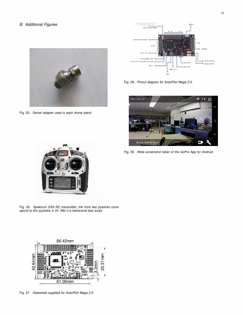
Fig. 25. Swivel adapter used in each drone stand.
Fig. 26. Spektrum DX8 RC transmitter; the front two joysticks corre-spond to the joysticks in Dr. Wei Li’s behavioral test script.
Fig. 27. Datasheet supplied for ArduPilot Mega 2.5.
Fig. 28. Pinout diagram for ArduPilot Mega 2.5.
Fig. 29. Wide screenshot taken of the GoPro App for Android.