49 001658 revab ww carbide series spec omega rgb ... · puis branchez l’extrémité à 9 broches...
TRANSCRIPT
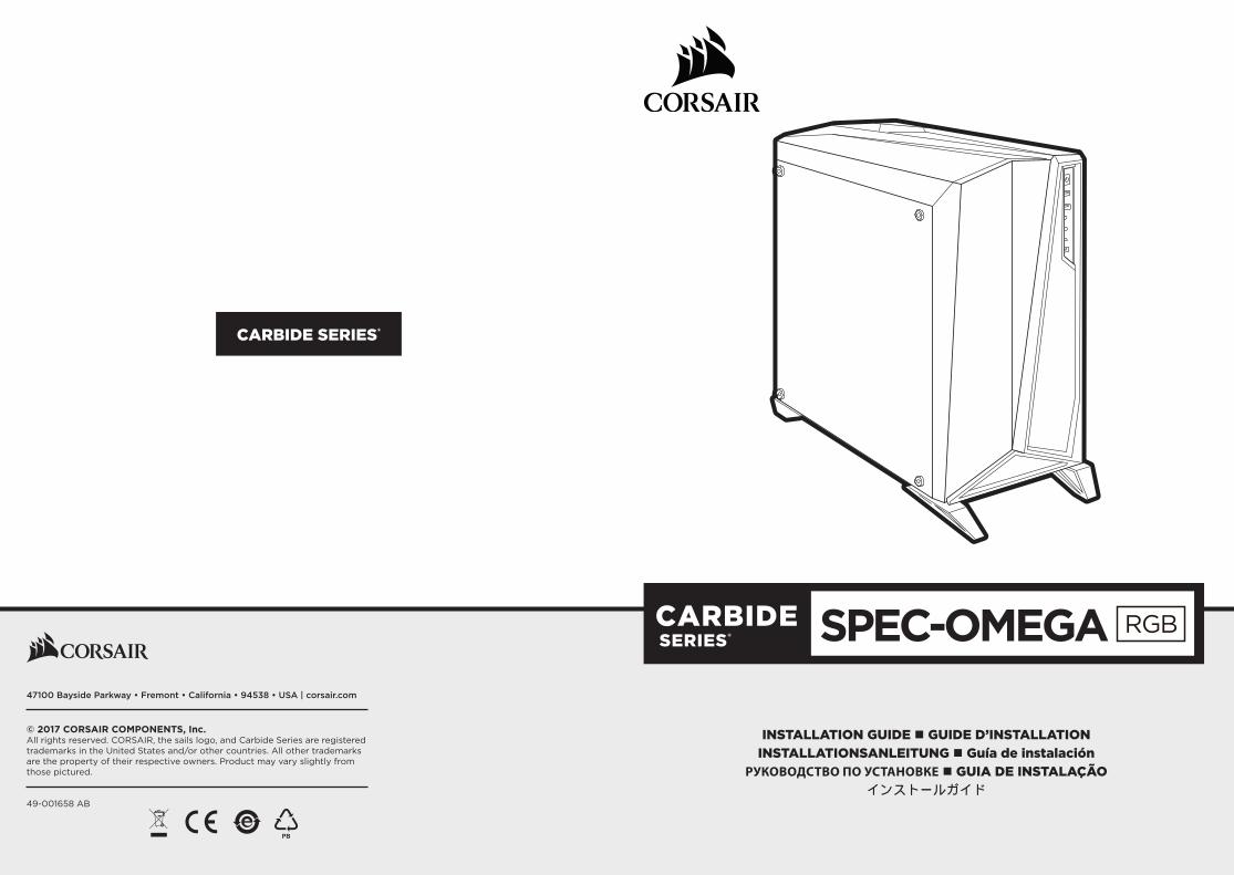
CARBIDE SERIES®
INSTALLATION GUIDE n GUIDE D’INSTALLATIONINSTALLATIONSANLEITUNG n Guía de instalación
РУКОВОДСТВО ПО УСТАНОВКЕ n GUIA DE INSTALAÇÃOインストールガイド
SPEC-OMEGA47100 Bayside Parkway • Fremont • California • 94538 • USA | corsair.com
© 2017 CORSAIR COMPONENTS, Inc.All rights reserved. CORSAIR, the sails logo, and Carbide Series are registered trademarks in the United States and/or other countries. All other trademarks are the property of their respective owners. Product may vary slightly from those pictured.
49-001658 AB
CARBIDE SERIES® SPEC-OMEGA RGB
21
233mm
516mm
495mm
EN
GLISH
Table of Contents Case Specifications
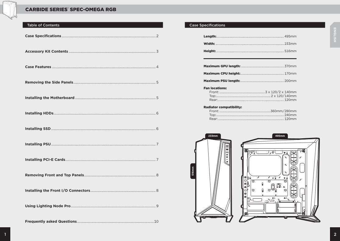
Length: ..................................................................................... 495mm
Width: ...................................................................................... 233mm
Height: ..................................................................................... 516mm
Maximum GPU length: ...................................................... 370mm
Maximum CPU height:....................................................... 170mm
Maximum PSU length: ....................................................... 200mm
Fan locations: Front: .........................................................3 x 120/2 x 140mm Top: .................................................................... 2 x 120/140mm Rear: ................................................................................... 120mm
Radiator compatibility: Front: ................................................................360mm/280mm Top: ..................................................................................... 240mm Rear: ................................................................................... 120mm
Case Specifications ......................................................................................................... 2
Accessory Kit Contents ................................................................................................. 3
Case Features .................................................................................................................... 4
Removing the Side Panels ............................................................................................ 5
Installing the Motherboard .......................................................................................... 5
Installing HDDs .................................................................................................................. 6
Installing SSD ..................................................................................................................... 6
Installing PSU ..................................................................................................................... 7
Installing PCI-E Cards ..................................................................................................... 7
Removing Front and Top Panels ................................................................................ 8
Installing the Front I/O Connectors ......................................................................... 8
Using Lighting Node Pro ............................................................................................... 9
Frequently asked Questions ......................................................................................10
CARBIDE SERIES® SPEC-OMEGA RGB
43
A
A
B
B
C
D
D
C
E
E
F
F
G
G
a
g
ed f
b c
EN
GLISH
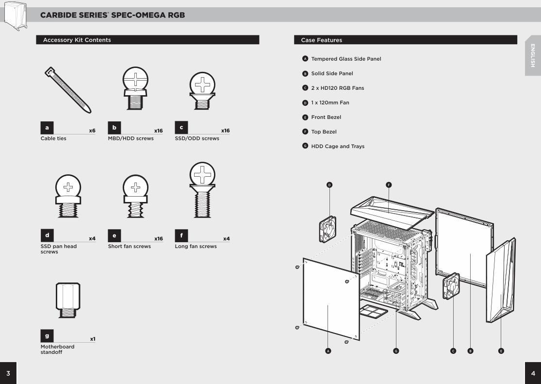
x6
x1
x16x4 x4
x16 x16
Case FeaturesAccessory Kit Contents
Tempered Glass Side Panel
Solid Side Panel
2 x HD120 RGB Fans
1 x 120mm Fan
Front Bezel
Top Bezel
HDD Cage and TraysCable ties
Motherboard standoff
Short fan screwsSSD pan head screws
Long fan screws
MBD/HDD screws SSD/ODD screws
CARBIDE SERIES® SPEC-OMEGA RGB
65
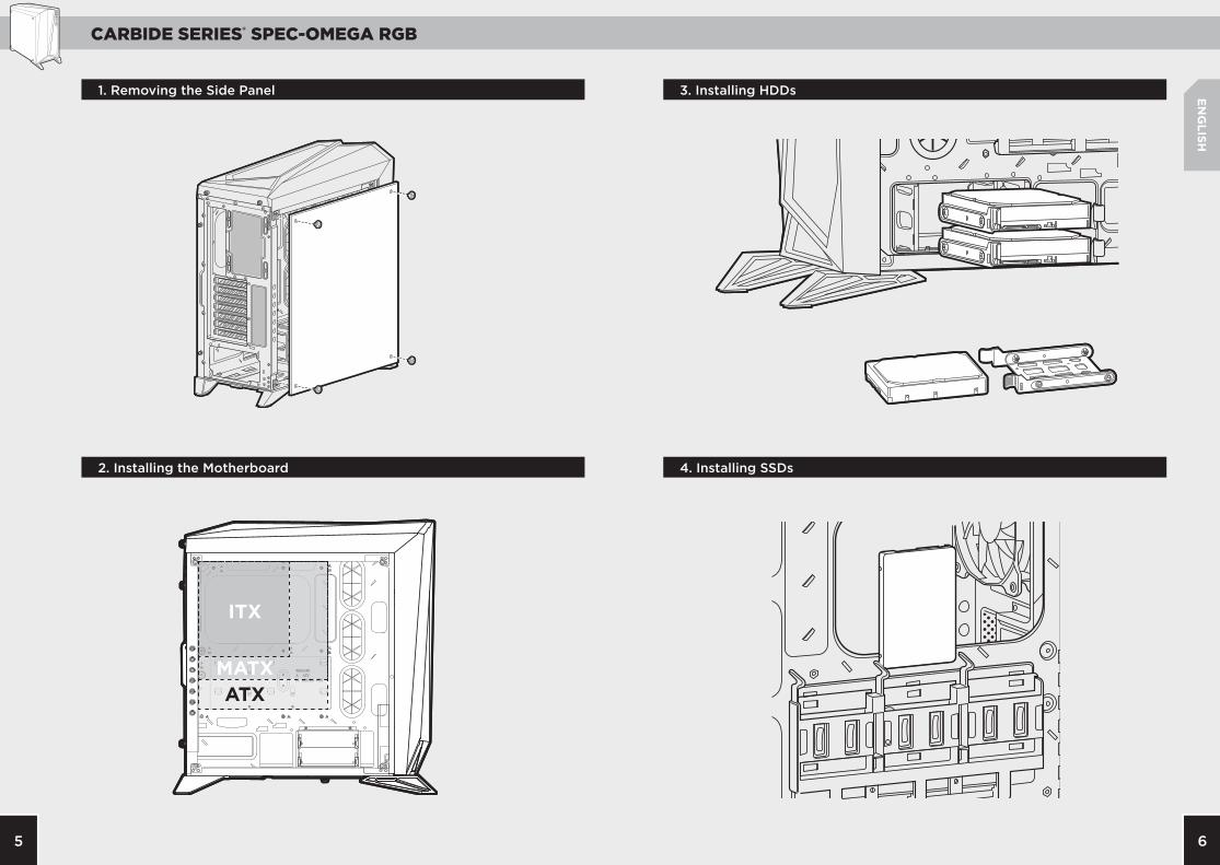
ITX
MATXATX
ITX
MATXATX
EN
GLISH
4. Installing SSDs
3. Installing HDDs
2. Installing the Motherboard
1. Removing the Side Panel

CARBIDE SERIES® SPEC-OMEGA RGB
87
USB 3.0
HD AUDIO RESET SWPOWER LED +
POWER LED –POWER SWHDD LED
EN
GLISH
7. Removing Front and Top Panels
8. Installing the Front I/O Connectors6. Installing PCI-E Cards
5. Installing PSU
CARBIDE SERIES® SPEC-OMEGA RGB
109
EN
GLISH
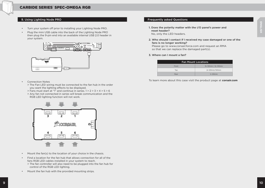
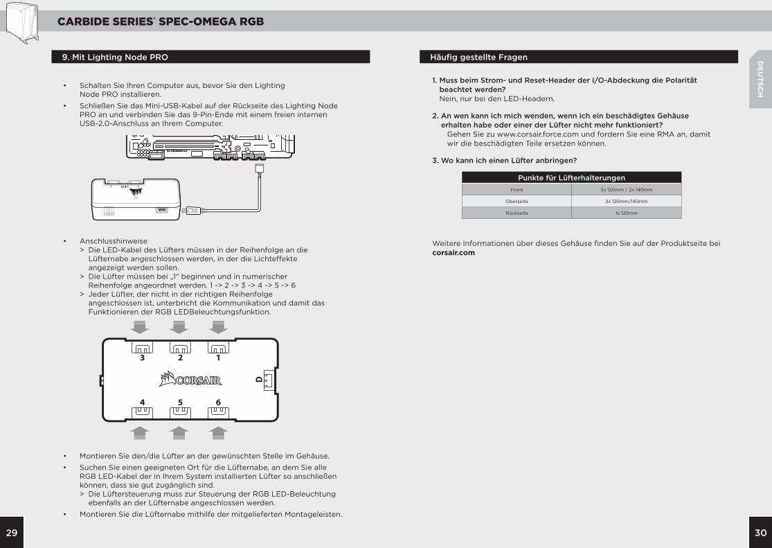
• Turn your system off prior to installing your Lighting Node PRO.
• Plug the mini USB cable into the back of the Lighting Node PRO then plug the 9-pin end into an available internal USB 2.0 header in your system.
• Connection Notes > The Fan LED wiring must be connected to the fan hub in the order you want the lighting effects to be displayed. > Fans must start at “1” and continue in series. 1 > 2 > 3 > 4 > 5 > 6 > Any fan not connected in series will break communication and the RGB LED lighting function will not work.
• Mount the fan(s) to the location of your choice in the chassis.
• Find a location for the fan hub that allows connection for all of the fans RGB LED cables installed in your system to reach. > The fan controller will also need to be plugged into the fan hub for
control of the RGB LED lighting.
• Mount the fan hub with the provided mounting strips.
9. Using Lighting Node PRO Frequently asked Questions
1. Does the polarity matter with the I/O panel’s power and reset header? No, only the LED headers.
2. Who should I contact if I received my case damaged or one of the fans is no longer working? Please go to www.corsair.force.com and request an RMA so that we can replace the damaged part(s).
3. Where can I mount a fan?
To learn more about this case visit the product page at corsair.com
Fan Mount LocationsFront 3x 120mm / 2x 140mm
Top 2x 120mm/140mm
Rear 1x 120mm

CARBIDE SERIES® SPEC-OMEGA RGB
1211
233mm
516mm
495mm
FRA
NÇ
AIS
Caractéristiques Techniques du Boîtier ................................................................12
Contenu du Kit D’accessoires ...................................................................................13
Attributs du Boîtier .......................................................................................................14
Retrait des Panneaux Latéraux ................................................................................15
Installation de la Carte Mère .....................................................................................15
Installation des Disques Durs ....................................................................................16
Installation des SSD ......................................................................................................16
Installation de L’alimentation ...................................................................................17
Installation des Cartes Pci-E/PCi ............................................................................17
Retrait des Panneaux Avant Et Supérieurs..........................................................18
Installation des Connecteurs E/S Avant ...............................................................18
Utilisation de Lighting Node Pro .............................................................................19
Foire aux Questions ......................................................................................................20
Table des Matières Caractéristiques Techniques du Boîtier
Longueur: ............................................................................... 495mm
Largeur: ................................................................................... 233mm
Hauteur: ................................................................................... 516mm
Longueur maximale de la carte graphique: ............ 370mm
Hauteur maximale du processeur: ............................... 170mm
Longueur maximale de l’alimentation: ...................... 200mm
Emplacement des ventilateurs: Avant: ...........................3 unités de 120 mm/2 de 140 mm Haut: .................................................. 2 unités de 120/140mm Arrière: .............................................................................. 120mm
Compatibilité des radiateurs: Avant: ...............................................................360mm/280mm Haut: ................................................................................... 240mm Arrière: .............................................................................. 120mm

CARBIDE SERIES® SPEC-OMEGA RGB
1413
A
A
B
B
C
D
D
C
E
E
F
F
G
G
a
g
ed f
b c
FRA
NÇ
AIS
x6
x1
x16x4 x4
x16 x16
Caractéristiques du BoîtierContenu du Kit D’accessoires
Panneau latéral en verre trempé
Panneau latéral plein
2 x HD120 RGB Ventilateur
1 x ventilateur de 120 mm
Panneau avant
Panneau supérieur
Cage de disque durAttaches de câbles
Entretoise de carte mère
Vis de ventilateur courtes
Vis à tête cylindrique pour disque SSD
Vis de ventilateur longues
Vis de carte mère/disque dur
Vis de SSD/lecteur optique
CARBIDE SERIES® SPEC-OMEGA RGB
1615
ITX
MATXATX
FRA
NÇ
AIS
4. Installation des SSD
3. Installation des Disques Durs
2. Installation de la Carte Mère
1. Retrait des Panneaux Latéraux

CARBIDE SERIES® SPEC-OMEGA RGB
1817
USB 3.0
HD AUDIO RESET SWPOWER LED +
POWER LED –POWER SWHDD LED
FRA
NÇ
AIS
7. Retrait des Panneaux Avant et Supérieur
8. Installation des Connecteurs d’e/S Avant6. Installation des Cartes PCI-E/PCI
5. Installation de L’alimentation
CARBIDE SERIES® SPEC-OMEGA RGB
2019
FRA
NÇ
AIS
Foire aux Questions
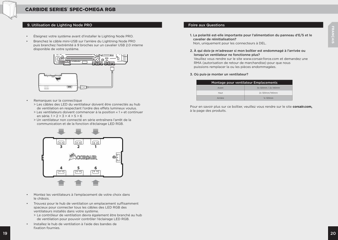
1. La polarité est-elle importante pour l'alimentation du panneau d'E/S et le cavalier de réinitialisation? Non, uniquement pour les connecteurs à DEL.
2. À qui dois-je m’adresser si mon boîtier est endommagé à l’arrivée ou lorsqu’un ventilateur ne fonctionne plus? Veuillez vous rendre sur le site www.corsair.force.com et demandez une RMA (autorisation de retour de marchandise) pour que nous puissions remplacer la ou les pièces endommagées.
3. Où puis-je monter un ventilateur?
Pour en savoir plus sur ce boîtier, veuillez vous rendre sur le site corsair.com, à la page des produits.
Montage pour ventilateur EmplacementsAvant 3x 120mm / 2x 140mm
Haut 2x 120mm/140mm
Arrière 1x 120mm
9. Utilisation de Lighting Node PRO
• Éteignez votre système avant d’installer le Lighting Node PRO.
• Branchez le câble mini-USB sur l’arrière du Lightning Node PRO puis branchez l’extrémité à 9 broches sur un cavalier USB 2.0 interne disponible de votre système.
• Remarques sur la connectique > Les câbles des LED du ventilateur doivent être connectés au hub de ventilation en respectant l’ordre des effets lumineux voulus. > Les ventilateurs doivent commencer à la position « 1 » et continuer en série. 1 > 2 > 3 > 4 > 5 > 6 > Un ventilateur non connecté en série entraînera l’arrêt de la communication et de la fonction d’éclairage LED RGB.
• Montez les ventilateurs à l’emplacement de votre choix dans le châssis.
• Trouvez pour le hub de ventilation un emplacement suffisamment spacieux pour connecter tous les câbles des LED RGB des ventilateurs installés dans votre système. > Le contrôleur de ventilation devra également être branché au hub de ventilation pour pouvoir contrôler l’éclairage LED RGB.
• Installez le hub de ventilation à l’aide des bandes de fixation fournies.
CARBIDE SERIES® SPEC-OMEGA RGB
2221
233mm
516mm
495mm
DE
UTSC
H
Technische Daten des Gehäuses ..............................................................................22
Inhalt des Zubehörkits .................................................................................................23
Funktionsmerkmale des Gehäuses .........................................................................24
Entfernen der Seitenplatten ......................................................................................25
Installation des Mainboards .......................................................................................25
Installation von HDD-Laufwerken ...........................................................................26
Installation von SSD-Laufwerken ............................................................................26
Installation des Netzteils ............................................................................................27
Installation der PCIe-/PCI-Karte(n) .......................................................................27
Vorder- und Deckplatten entfernen .......................................................................28
Installation der vorderen I/O-Anschlüsse............................................................28
Mit Lighting Node PRO ................................................................................................29
Häufig gestellte Fragen ...............................................................................................30
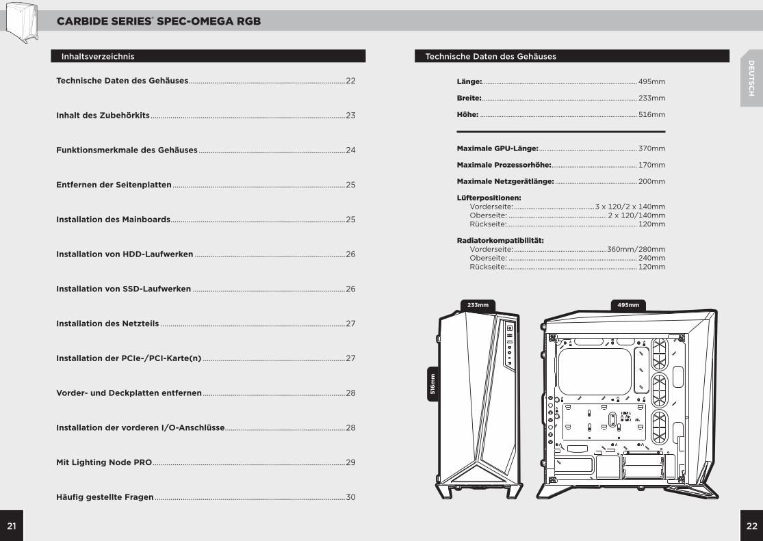
Inhaltsverzeichnis Technische Daten des Gehäuses
Länge:....................................................................................... 495mm
Breite: ....................................................................................... 233mm
Höhe: ........................................................................................ 516mm
Maximale GPU-Länge: ....................................................... 370mm
Maximale Prozessorhöhe: ................................................ 170mm
Maximale Netzgerätlänge: .............................................. 200mm
Lüfterpositionen: Vorderseite: .............................................3 x 120/2 x 140mm Oberseite: ....................................................... 2 x 120/140mm Rückseite:......................................................................... 120mm
Radiatorkompatibilität: Vorderseite: ....................................................360mm/280mm Oberseite: ........................................................................ 240mm Rückseite:......................................................................... 120mm

CARBIDE SERIES® SPEC-OMEGA RGB
2423
A
A
B
B
C
D
D
C
E
E
F
F
G
G
a
g
ed f
b c
DE
UTSC
H
x6
x1
x16x4 x4
x16 x16
Funktionsmerkmale des GehäusesInhalt des Zubehörkits
Kabelbinder
Motherboard-Abstandsbolzen
Kurze Lüfterschrauben
SSD-Becherschrauben
Lange Lüfterschrauben
MBD/HDD-Schrauben SSD/ODD-Schrauben
Seitenabdeckung aus gehärtetem Glas
Massive Seitenabdeckung
2 x HD120 RGB Lüfter
1 x 120mm Lüfter
Vordere Blende
Obere lünette
HDD Käfig und Trays

CARBIDE SERIES® SPEC-OMEGA RGB
2625
ITX
MATXATX
DE
UTSC
H
4. Installation von SSD-Laufwerken
3. Installation von HDD-Laufwerken
2. Installation des Mainboards
1. Entfernen der Seitenplatten

CARBIDE SERIES® SPEC-OMEGA RGB
2827
USB 3.0
HD AUDIO RESET SWPOWER LED +
POWER LED –POWER SWHDD LED
DE
UTSC
H
7. Removing Front and Top Panels
8. Vorder- und Deckplatten entfernen 6. Installation der PCIe-/PCI-Karte(n)
5. Installation des Netzteils
CARBIDE SERIES® SPEC-OMEGA RGB
3029
DE
UTSC
H
1. Muss beim Strom- und Reset-Header der I/O-Abdeckung die Polarität beachtet werden? Nein, nur bei den LED-Headern.
2. An wen kann ich mich wenden, wenn ich ein beschädigtes Gehäuse erhalten habe oder einer der Lüfter nicht mehr funktioniert? Gehen Sie zu www.corsair.force.com und fordern Sie eine RMA an, damit
wir die beschädigten Teile ersetzen können.
3. Wo kann ich einen Lüfter anbringen?
Weitere Informationen über dieses Gehäuse finden Sie auf der Produktseite bei corsair.com
Punkte für LüfterhalterungenFront 3x 120mm / 2x 140mm
Oberseite 2x 120mm/140mm
Rückseite 1x 120mm
Häufig gestellte Fragen9. Mit Lighting Node PRO
• Schalten Sie Ihren Computer aus, bevor Sie den Lighting Node PRO installieren.
• Schließen Sie das Mini-USB-Kabel auf der Rückseite des Lighting Node PRO an und verbinden Sie das 9-Pin-Ende mit einem freien internen USB-2.0-Anschluss an Ihrem Computer.
• Anschlusshinweise > Die LED-Kabel des Lüfters müssen in der Reihenfolge an die Lüfternabe angeschlossen werden, in der die Lichteffekte angezeigt werden sollen. > Die Lüfter müssen bei „1“ beginnen und in numerischer Reihenfolge angeordnet werden. 1 -> 2 -> 3 -> 4 -> 5 -> 6 > Jeder Lüfter, der nicht in der richtigen Reihenfolge angeschlossen ist, unterbricht die Kommunikation und damit das Funktionieren der RGB LEDBeleuchtungsfunktion.
• Montieren Sie den/die Lüfter an der gewünschten Stelle im Gehäuse.
• Suchen Sie einen geeigneten Ort für die Lüfternabe, an dem Sie alle RGB LED-Kabel der in Ihrem System installierten Lüfter so anschließen können, dass sie gut zugänglich sind. > Die Lüftersteuerung muss zur Steuerung der RGB LED-Beleuchtung ebenfalls an der Lüfternabe angeschlossen werden.
• Montieren Sie die Lüfternabe mithilfe der mitgelieferten Montageleisten.
CARBIDE SERIES® SPEC-OMEGA RGB
3231
233mm
516mm
495mm
ESPA
ÑO
L
Contenido Especificaciones del Chasis
Especificaciones del Chasis .......................................................................................32
Contenido del Conjunto De Accesorios ...............................................................33
Características del Chasis ...........................................................................................34
Retirada de los Paneles Laterales ...........................................................................35
Instalación de la Placa Base ......................................................................................35
Instalación de las Unidades Hdd .............................................................................36
Instalación de las Unidades Ssd ..............................................................................36
Instalación de la Psu .....................................................................................................37
Instalación de las Tarjetas Pci-E/Pci ......................................................................37
Extracción de los Paneles Delantero Y Superior ..............................................38
Instalación de los Conectores De E/S Frontales ..............................................38
Usando Ighting Node Pro ...........................................................................................39
Preguntas más Frecuentes .........................................................................................40
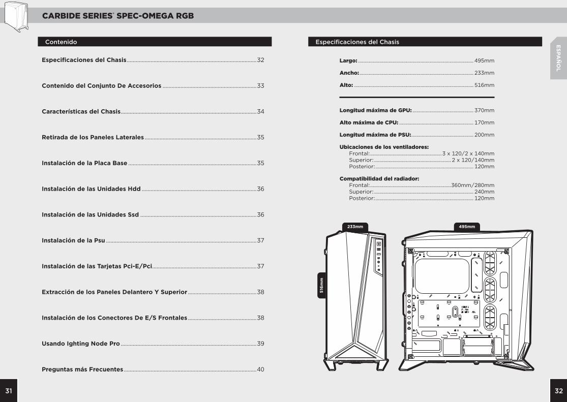
Largo: ....................................................................................... 495mm
Ancho: ...................................................................................... 233mm
Alto: .......................................................................................... 516mm
Longitud máxima de GPU: .............................................. 370mm
Alto máxima de CPU: ........................................................ 170mm
Longitud máxima de PSU: ............................................... 200mm
Ubicaciones de los ventiladores: Frontal: ......................................................3 x 120/2 x 140mm Superior: .......................................................... 2 x 120/140mm Posterior: .......................................................................... 120mm
Compatibilidad del radiador: Frontal: .............................................................360mm/280mm Superior: ........................................................................... 240mm Posterior: .......................................................................... 120mm

CARBIDE SERIES® SPEC-OMEGA RGB
3433
A
A
B
B
C
D
D
C
E
E
F
F
G
G
a
g
ed f
b c
ESPA
ÑO
L
x6
x1
x16x4 x4
x16 x16
Características del ChasisContenido del Conjunto de Accesorios
Ataduras para cables
Apoyo para placa base
Tornillos cortos para ventiladores
Tornillos de cabeza troncocónica para SSD
Tornillos largos para ventiladores
Tornillos para MBD/HDD
Tornillos para SSD/ODD
Panel lateral de cristal templado
Painel lateral sólido
2 x ventiladores HD120 RGB
1 x ventilador de 120mm
Embellecedor frontal
Bisel superior
Jaula de discos duros y bandejas

CARBIDE SERIES® SPEC-OMEGA RGB
3635
ITX
MATXATX
ESPA
ÑO
L
4. Instalación de las Unidades SSD
3. Instalación de las Unidades HDD
2. Instalación de la Placa Base
1. Cómo Remover los Paneles Laterales

CARBIDE SERIES® SPEC-OMEGA RGB
3837
USB 3.0
HD AUDIO RESET SWPOWER LED +
POWER LED –POWER SWHDD LED
ESPA
ÑO
L
7. Extracción de los Paneles Delantero y Superior
8. Instalación de los Conectores de E/S Frontales6. Instalación de las Tarjetas PCI-E/PCI
5. Instalación de la PSU
CARBIDE SERIES® SPEC-OMEGA RGB
4039
ESPA
ÑO
L
Preguntas Frecuentes
1 . ¿Es importante la polaridad al instalar el cabezal de reinicio y de encendido del panel I/O? No, sólo los cabezales LED.
2. ¿Con quién me debo poner en contacto si recibo mi chasis dañado o uno de los ventiladores ya no funciona? Por favor, diríjase a www.corsair.force.com y pida un RMA para que podamos reemplazar las piezas dañadas.
3. ¿Dónde puedo montar un ventilador?
Para obtener más información sobre este chasis, visite la página del producto en corsair.com
Puntos de montaje para ventiladoresParte delantera 3x 120mm / 2x 140mm
Parte superior 2x 120mm/140mm
Parte superior 1x 120mm
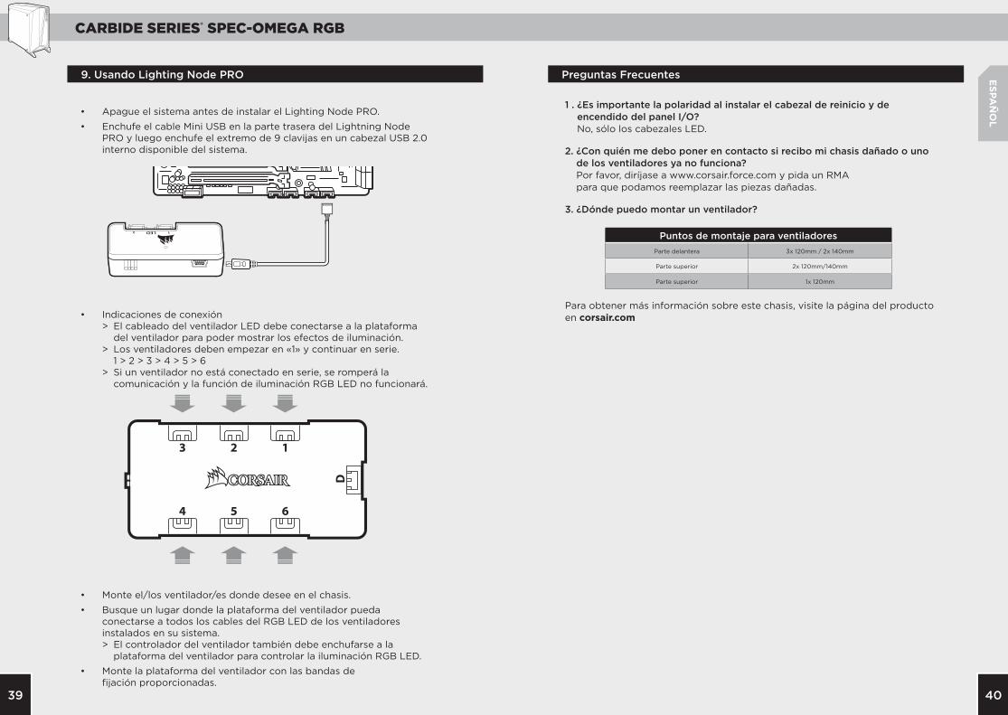
• Apague el sistema antes de instalar el Lighting Node PRO.
• Enchufe el cable Mini USB en la parte trasera del Lightning Node PRO y luego enchufe el extremo de 9 clavijas en un cabezal USB 2.0 interno disponible del sistema.
• Indicaciones de conexión > El cableado del ventilador LED debe conectarse a la plataforma del ventilador para poder mostrar los efectos de iluminación. > Los ventiladores deben empezar en «1» y continuar en serie. 1 > 2 > 3 > 4 > 5 > 6 > Si un ventilador no está conectado en serie, se romperá la comunicación y la función de iluminación RGB LED no funcionará.
• Monte el/los ventilador/es donde desee en el chasis.
• Busque un lugar donde la plataforma del ventilador pueda conectarse a todos los cables del RGB LED de los ventiladores instalados en su sistema. > El controlador del ventilador también debe enchufarse a la plataforma del ventilador para controlar la iluminación RGB LED.
• Monte la plataforma del ventilador con las bandas de fijación proporcionadas.
9. Usando Lighting Node PRO
CARBIDE SERIES® SPEC-OMEGA RGB
4241
233mm
516mm
495mm
РУССКИ
Й
Содержание Технические Характеристики Корпуса
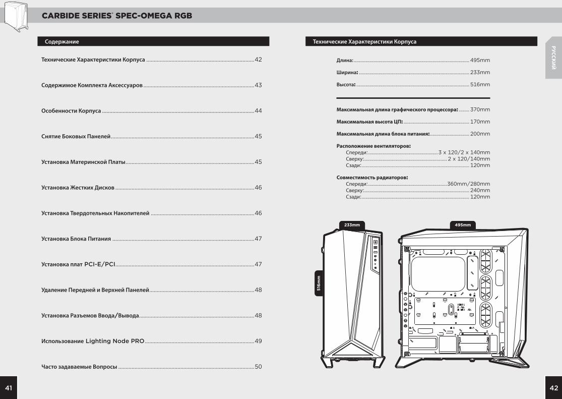
Длина: ........................................................................................ 495mm
Ширина: .................................................................................... 233mm
Высота: ...................................................................................... 516mm
Максимальная длина графического процессора: ........ 370mm
Максимальная высота ЦП: .................................................. 170mm
Максимальная длина блока питания: .............................. 200mm
Расположение вентиляторов: Спереди: .....................................................3 x 120/2 x 140mm Сверху: ............................................................... 2 x 120/140mm Сзади: .................................................................................. 120mm
Совместимость радиаторов: Спереди: ............................................................360mm/280mm Сверху: ................................................................................ 240mm Сзади: .................................................................................. 120mm
Технические Характеристики Корпуса .........................................................................42
Содержимое Комплекта Аксессуаров ...........................................................................43
Особенности Корпуса .......................................................................................................44
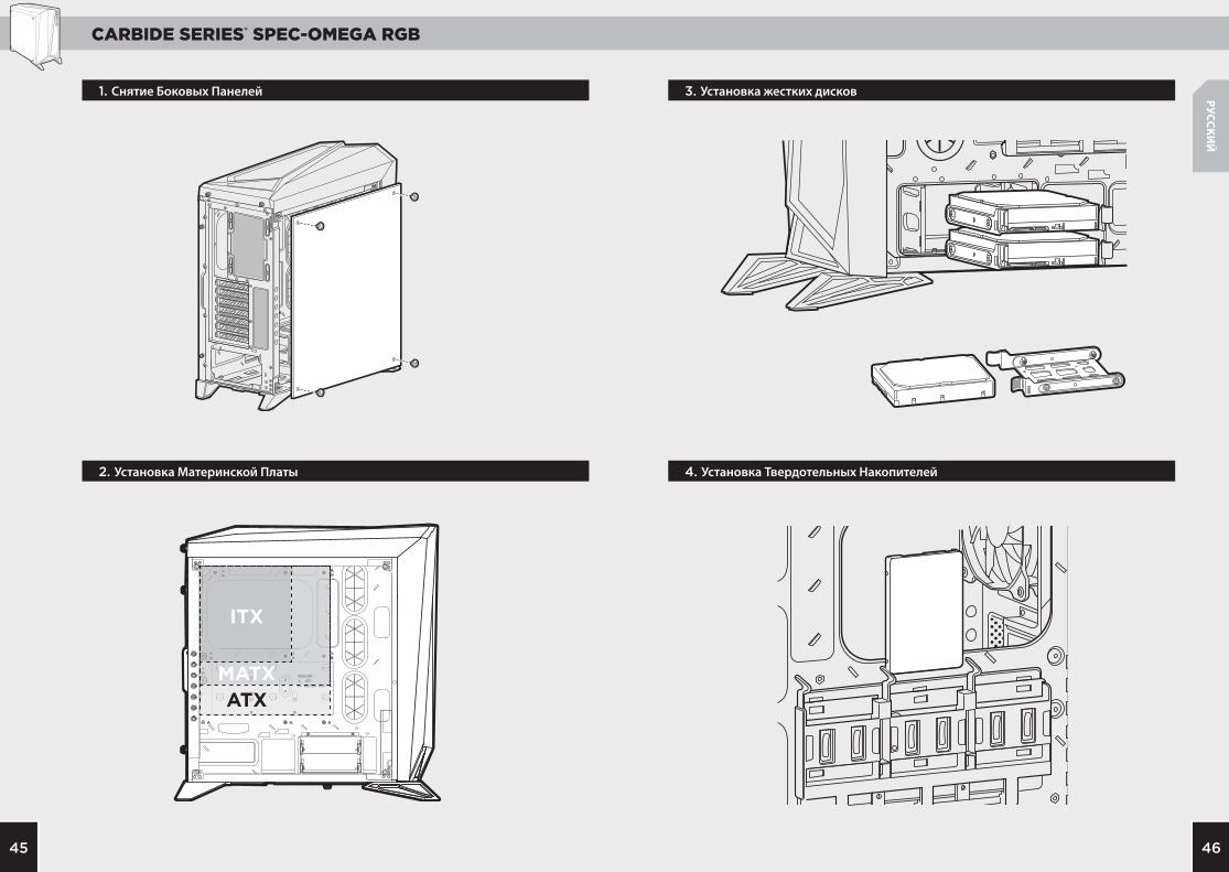
Снятие Боковых Панелей .................................................................................................45
Установка Материнской Платы .......................................................................................45
Установка Жестких Дисков ..............................................................................................46
Установка Твердотельных Накопителей ......................................................................46
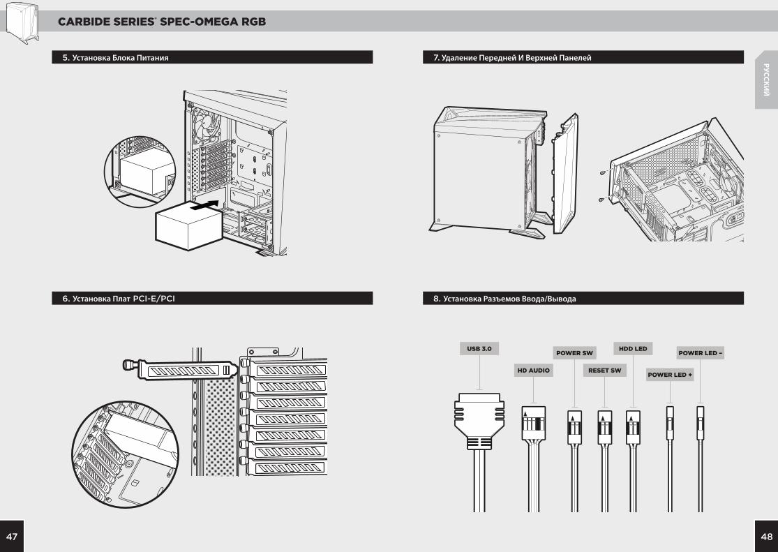
Установка Блока Питания ................................................................................................47
Установка плат PCI-E/PCI ..............................................................................................47
Удаление Передней и Верхней Панелей .......................................................................48
Установка Разъемов Ввода/Вывода..............................................................................48
Использование Lighting Node PRO ..........................................................................49
Часто задаваемые Вопросы ............................................................................................50

CARBIDE SERIES® SPEC-OMEGA RGB
4443
A
A
B
B
C
D
D
C
E
E
F
F
G
G
a
g
ed f
b c
РУССКИ
Й
x6
x1
x16x4 x4
x16 x16Кабельные стяжки
Изолирующие винты для материнской платы
Короткие винты для вентилятора
Винты с округленной головкой для твердотельных накопителей
Длинные винты для вентилятора
Винты для материнской платы или жестких дисков
Винты для твердотельных накопителей или оптических дисков
Боковая панель из закаленного стекла
Цельная боковая панель
2 x HD120 RGB-вентиляторы
Вентилятор 1 x 120 мм
Передний ободок
Верхняя рамка
Жесткие диски и лотки
Особенности КорпусаСодержимое Комплекта Аксессуаров
CARBIDE SERIES® SPEC-OMEGA RGB
4645
ITX
MATXATX
РУССКИ
Й
4. Установка Твердотельных Накопителей
3. Установка жестких дисков
2. Установка Материнской Платы
1. Снятие Боковых Панелей
CARBIDE SERIES® SPEC-OMEGA RGB
4847
USB 3.0
HD AUDIO RESET SWPOWER LED +
POWER LED –POWER SWHDD LED
РУССКИ
Й
7. Удаление Передней И Верхней Панелей
8. Установка Разъемов Ввода/Вывода6. Установка Плат PCI-E/PCI
5. Установка Блока Питания
CARBIDE SERIES® SPEC-OMEGA RGB
5049
РУССКИ
Й
Часто Задаваемые Вопросы
1. Имеет ли значение полярность при использовании разъема питания и перезагрузки на панели ввода-вывода? Нет, она важна только для светодиодных разъемов.
2. К кому следует обратиться, если корпус получен поврежденным или один из вентиляторов больше не работает? Перейдите на веб-сайт www.corsair.force.com и запросите разрешение на возврат материалов (RMA), чтобы мы смогли заменить поврежденные детали.
3. Где можно установить вентилятор?
Дополнительную информацию об этом корпусе см. на странице продукта на веб-сайте corsair.com
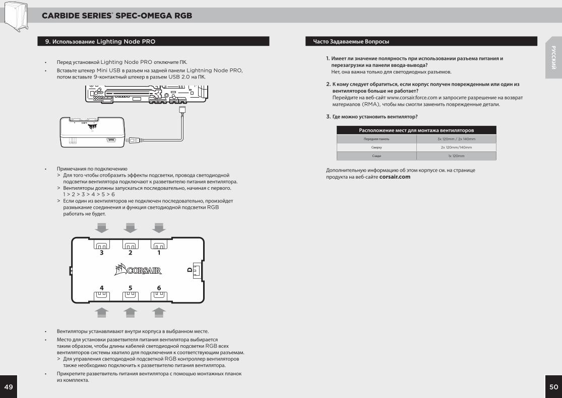
Расположение мест для монтажа вентиляторовПередняя панель 3x 120mm / 2x 140mm
Сверху 2x 120mm/140mm
Сзади 1x 120mm
• Перед установкой Lighting Node PRO отключите ПК.
• Вставьте штекер Mini USB в разъем на задней панели Lightning Node PRO, потом вставьте 9-контактный штекер в разъем USB 2.0 на ПК.
• Примечания по подключению > Для того чтобы отобразить эффекты подсветки, провода светодиодной подсветки вентилятора подключают к разветвителю питания вентилятора. > Вентиляторы должны запускаться последовательно, начиная с первого. 1 > 2 > 3 > 4 > 5 > 6 > Если один из вентиляторов не подключен последовательно, произойдет размыкание соединения и функция светодиодной подсветки RGB работать не будет.
• Вентиляторы устанавливают внутри корпуса в выбранном месте.
• Место для установки разветвителя питания вентилятора выбирается таким образом, чтобы длины кабелей светодиодной подсветки RGB всех вентиляторов системы хватило для подключения к соответствующим разъемам. > Для управления светодиодной подсветкой RGB контроллер вентиляторов также необходимо подключить к разветвителю питания вентилятора.
• Прикрепите разветвитель питания вентилятора с помощью монтажных планок из комплекта.
9. Использование Lighting Node PRO
CARBIDE SERIES® SPEC-OMEGA RGB
5251
233mm
516mm
495mm
PO
RTU
GU
ÊS
Índice Especificações do Gabinete
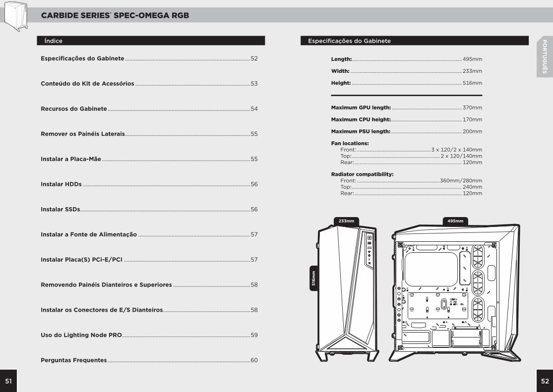
Length: ..................................................................................... 495mm
Width: ...................................................................................... 233mm
Height: ..................................................................................... 516mm
Maximum GPU length: ...................................................... 370mm
Maximum CPU height:....................................................... 170mm
Maximum PSU length: ....................................................... 200mm
Fan locations: Front: .........................................................3 x 120/2 x 140mm Top: .................................................................... 2 x 120/140mm Rear: ................................................................................... 120mm
Radiator compatibility: Front: ................................................................360mm/280mm Top: ..................................................................................... 240mm Rear: ................................................................................... 120mm
Especificações do Gabinete ......................................................................................52
Conteúdo do Kit de Acessórios ...............................................................................53
Recursos do Gabinete ..................................................................................................54
Remover os Painéis Laterais ......................................................................................55
Instalar a Placa-Mãe ......................................................................................................55
Instalar HDDs ...................................................................................................................56
Instalar SSDs.....................................................................................................................56
Instalar a Fonte de Alimentação .............................................................................57
Instalar Placa(S) PCi-E/PCI .......................................................................................57
Removendo Painéis Dianteiros e Superiores .....................................................58
Instalar os Conectores de E/S Dianteiros ............................................................58
Uso do Lighting Node PRO ........................................................................................59
Perguntas Frequentes ..................................................................................................60

CARBIDE SERIES® SPEC-OMEGA RGB
5453
A
A
B
B
C
D
D
C
E
E
F
F
G
G
a
g
ed f
b c
PO
RTU
GU
ÊS
x6
x1
x16x4 x4
x16 x16
Recursos do GabineteConteúdo do Kit de Acessórios
Braçadeiras para cabos
Suporte da placa-mãe
Parafusos curtos para ventoinha
Parafusos de cabeça panela para SSD
Parafusos longos para ventoinha
Parafusos para MBD/HDD
Parafusos para SSD/ODD
Painel lateral em vidro temperado
Panel lateral sólido
2 x Ventoinhas HD120 RGB
1 x ventilador de 120 mm
Bezel dianteiro
Topo dianteiro
HDD Cage e Bandejas

CARBIDE SERIES® SPEC-OMEGA RGB
5655
ITX
MATXATX
PO
RTU
GU
ÊS
4. Instalar SSDs
3. Instalar HDDs
2. Instalar a Placa-Mãe
1. Remover os Painéis Laterais

CARBIDE SERIES® SPEC-OMEGA RGB
5857
USB 3.0
HD AUDIO RESET SWPOWER LED +
POWER LED –POWER SWHDD LED
PO
RTU
GU
ÊS
7. Removendo Painéis Dianteiros e Superiores
8. Instalar os Conectores de E/S Dianteiros6. Instalar Placa(s) PCI-E/PCI
5. Instalar a Fonte de Alimentação

CARBIDE SERIES® SPEC-OMEGA RGB
6059
PO
RTU
GU
ÊS
Perguntas Frequentes
1. A polaridade é importante quando o painel de E/S alimenta e reinicia a haste? Não, apenas as hastes do LED.
2. Quem devo contatar caso receba meu gabinete danificado ou uma das ventoinhas não estiver mais funcionando? Acesse www.corsair.force.com e solicite um RMA, para que possamos substituir a(s) peça(s) danificada(s).
3. Onde posso montar uma ventoinha?
Para saber mais sobre este gabinete, visite a página do produto em corsair.com
Montar um fãFrente 3x 120mm / 2x 140mm
Topo 2x 120mm/140mm
Traseira 1x 120mm
• Desligue o sistema antes de instalar o Lighting Node PRO.
• Conecte o cabo USB na parte traseira do Lighting Node PRO e, em seguida, insira o conector de 9 pinos em um slot USB 2.0 interno do sistema.
• Notas de ligação > A fiação do LED da ventoinha deve estar conectada ao hub na ordem pretendida para a exibição dos efeitos de luz. > As ventoinhas devem começar em “1” e continuar em série. 1 > 2 > 3 > 4 > 5 > 6 > Qualquer ventoinha que não esteja ligada em série quebrará a comunicação e a função de iluminação LED RGB não funcionará.
• Instale a(s) ventoinha(s) no local desejado no chassi.
• Procure um local para o hub que permita a conexão de todos os cabos LED RGB das ventoinhas instalados em seu sistema. > Também é necessário conectar o controlador da ventoinha ao hub para controlar a iluminação LED RGB.
• Monte o hub com as fitas de montagem fornecidas.
9. Uso do Lighting Node PRO
CARBIDE SERIES® SPEC-OMEGA RGB
6261
233mm
516mm
495mm
日本
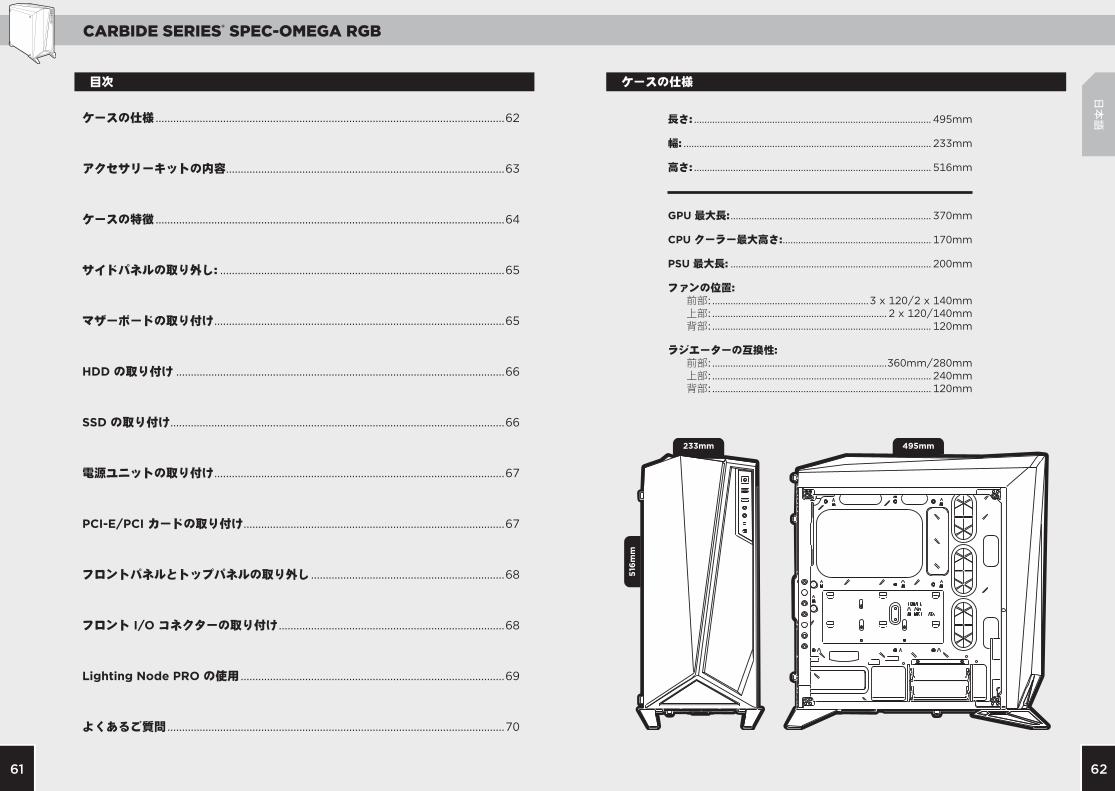
語ケースの仕様 .......................................................................................................................62
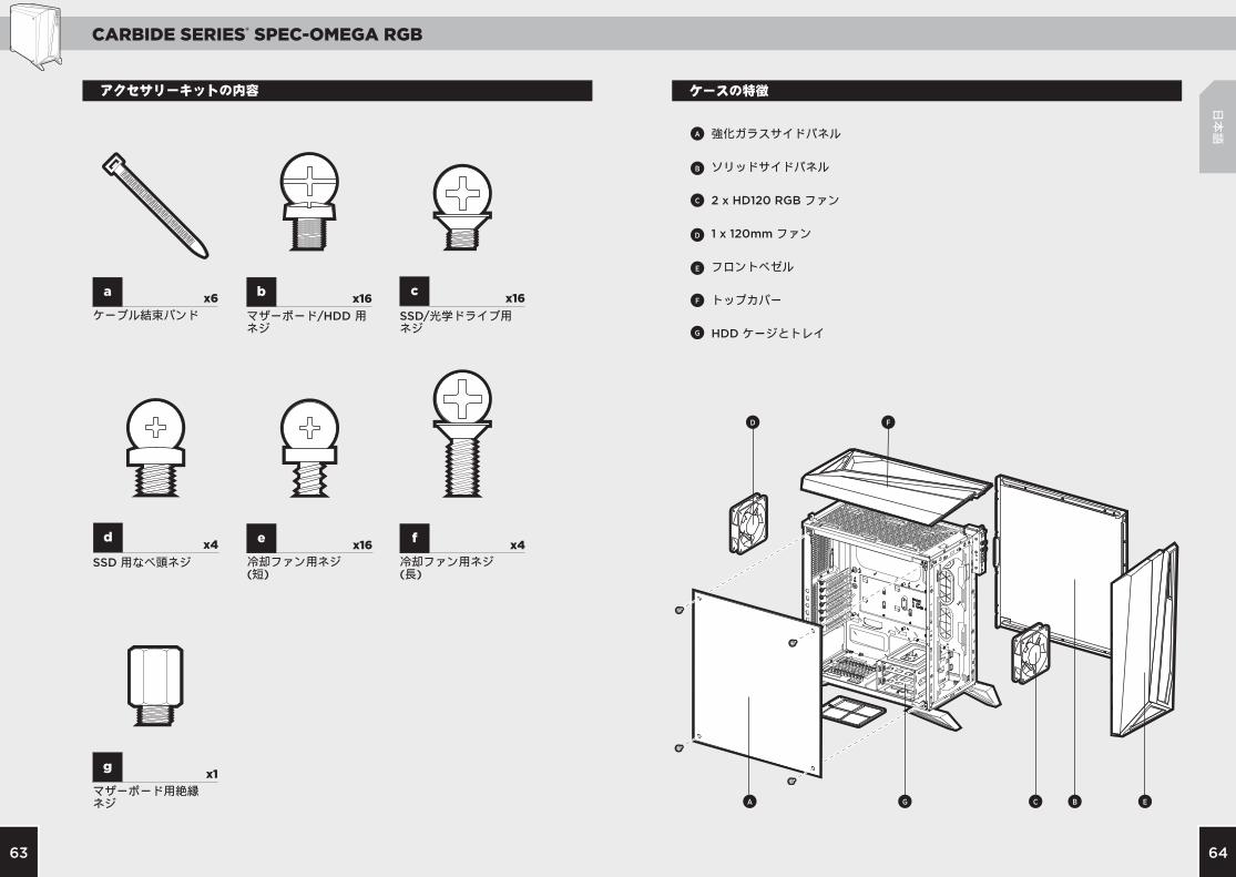
アクセサリーキットの内容 ...............................................................................................63
ケースの特徴 .......................................................................................................................64
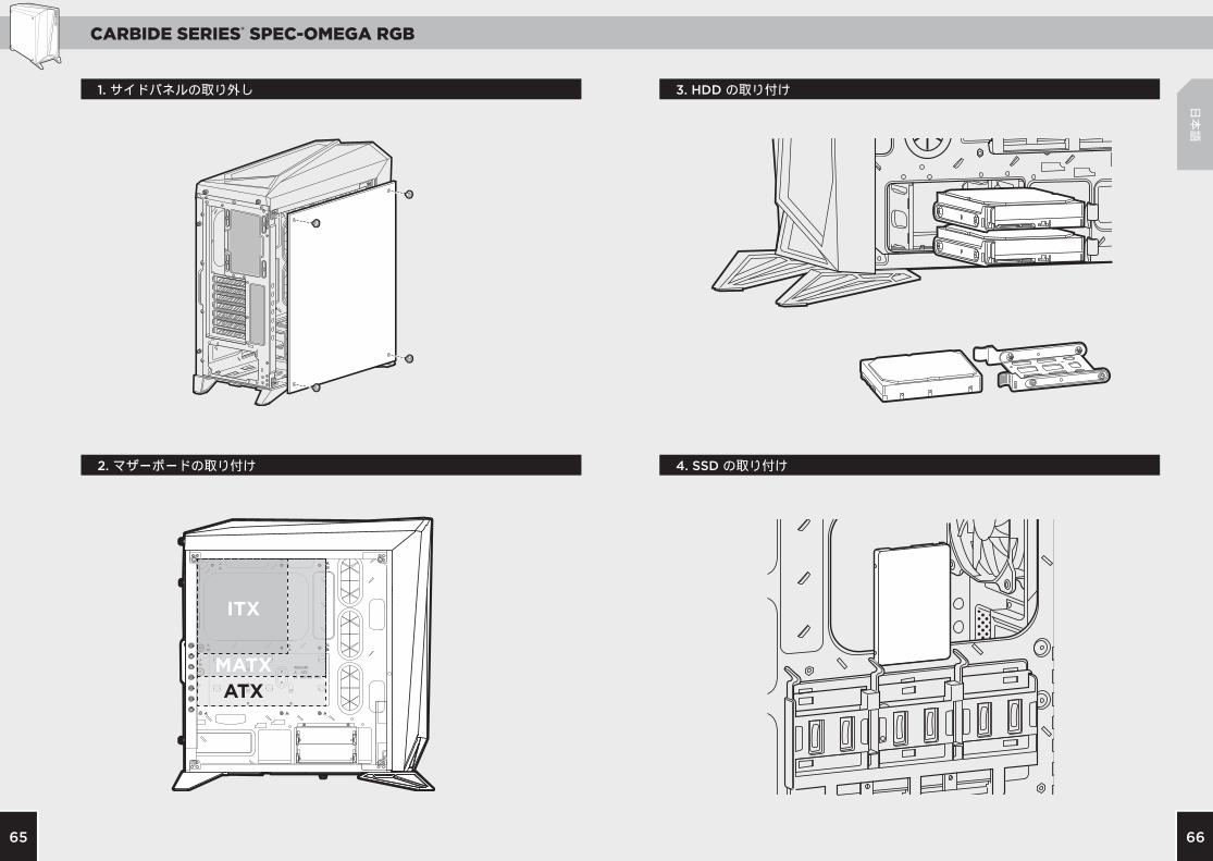
サイドパネルの取り外し: .................................................................................................65
マザーボードの取り付け ...................................................................................................65
HDD の取り付け ................................................................................................................66
SSD の取り付け..................................................................................................................66
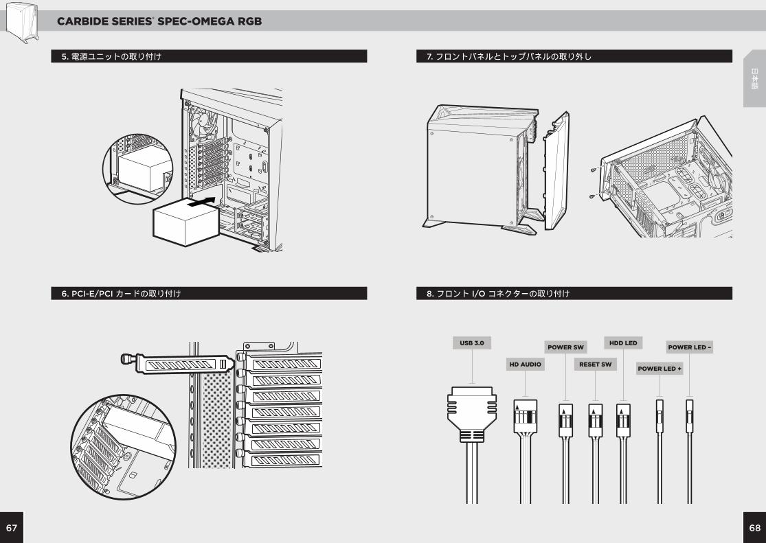
電源ユニットの取り付け ...................................................................................................67
PCI-E/PCI カードの取り付け .........................................................................................67
フロントパネルとトップパネルの取り外し ..................................................................68
フロント I/O コネクターの取り付け .............................................................................68
Lighting Node PRO の使用 ..........................................................................................69
よくあるご質問 ...................................................................................................................70
目次 ケースの仕様
長さ: ........................................................................................... 495mm
幅: ............................................................................................... 233mm
高さ: ........................................................................................... 516mm
GPU 最大長: ............................................................................. 370mm
CPU クーラー最大高さ: ......................................................... 170mm
PSU 最大長: ............................................................................. 200mm
ファンの位置: 前部: ............................................................3 x 120/2 x 140mm 上部: ................................................................... 2 x 120/140mm 背部: .................................................................................... 120mm
ラジエーターの互換性: 前部: ...................................................................360mm/280mm 上部: .................................................................................... 240mm 背部: .................................................................................... 120mm
CARBIDE SERIES® SPEC-OMEGA RGB
6463
A
A
B
B
C
D
D
C
E
E
F
F
G
G
a
g
ed f
b c
日本
語
x6
x1
x16x4 x4
x16 x16
ケースの特徴アクセサリーキットの内容
ケーブル結束バンド
マザーボード用絶縁ネジ
冷却ファン用ネジ (短)
SSD 用なべ頭ネジ 冷却ファン用ネジ (長)
マザーボード/HDD 用ネジ
SSD/光学ドライブ用ネジ
強化ガラスサイドパネル
ソリッドサイドパネル
2 x HD120 RGB ファン
1 x 120mm ファン
フロントベゼル
トップカバー
HDD ケージとトレイ
CARBIDE SERIES® SPEC-OMEGA RGB
6665
ITX
MATXATX
日本
語
4. SSD の取り付け
3. HDD の取り付け
2. マザーボードの取り付け
1. サイドパネルの取り外し
CARBIDE SERIES® SPEC-OMEGA RGB
6867
USB 3.0
HD AUDIO RESET SWPOWER LED +
POWER LED –POWER SWHDD LED
日本
語
7. フロントパネルとトップパネルの取り外し
8. フロント I/O コネクターの取り付け6. PCI-E/PCI カードの取り付け
5. 電源ユニットの取り付け
CARBIDE SERIES® SPEC-OMEGA RGB
7069
日本
語
よくあるご質問
1. I/O パネルの電源とリセットヘッダーで極性は重要ですか? いいえ。LED のヘッダーでのみ重要です。
2. 破損したケースを受け取ったか、またはファンが動作しない場合、誰に連絡すべきですか? 弊社の Web サイト (www.corsair.force.com) にアクセスし、 破損した部品の交換について RMA を依頼してください。
3. どこにファンを搭載できますか?
ケースの詳細情報は、弊社の製品ページ (corsair.com) にアクセスしてください。
ファンマウントの位置
前面 3x 120mm / 2x 140mm
上面 2x 120mm/140mm
背面 1x 120mm
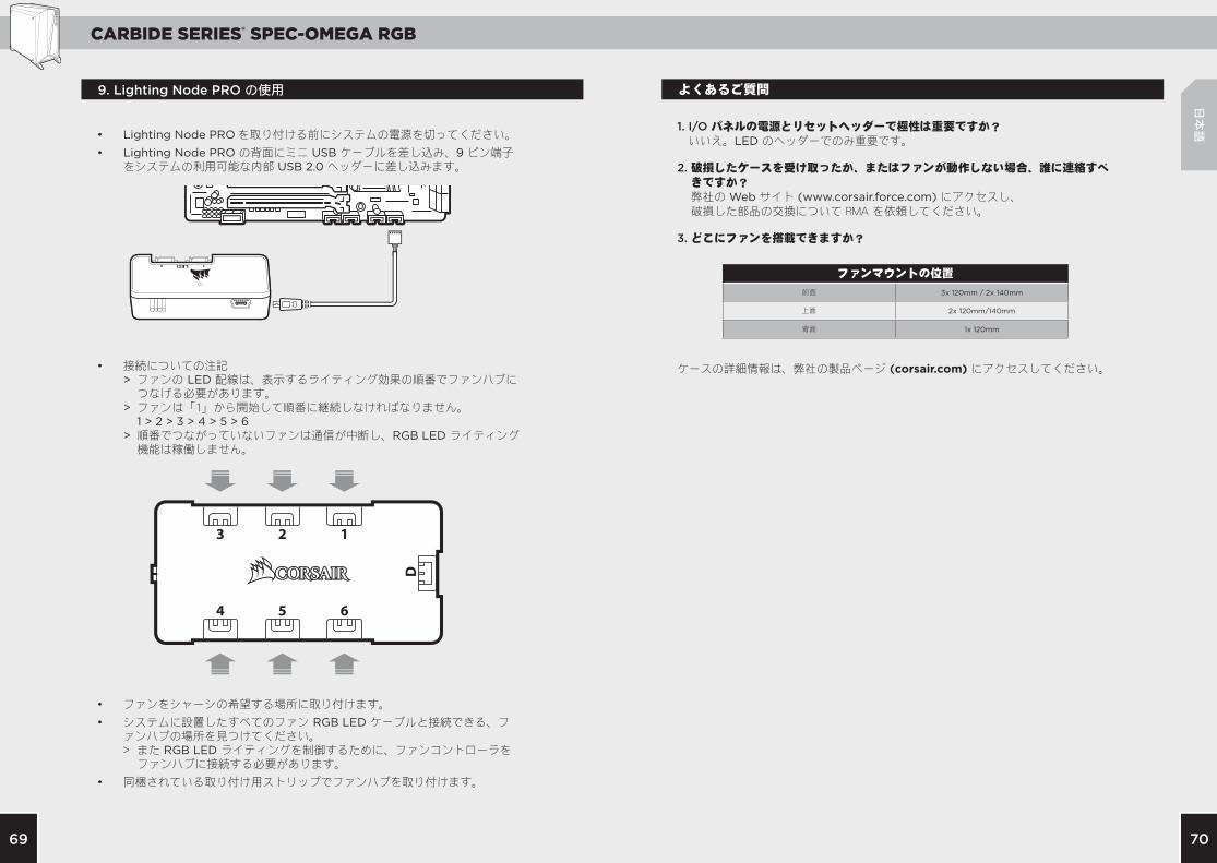
• Lighting Node PRO を取り付ける前にシステムの電源を切ってください。
• Lighting Node PRO の背面にミニ USB ケーブルを差し込み、9 ピン端子をシステムの利用可能な内部 USB 2.0 ヘッダーに差し込みます。
• 接続についての注記 > ファンの LED 配線は、表示するライティング効果の順番でファンハブに つなげる必要があります。 > ファンは「1」から開始して順番に継続しなければなりません。 1 > 2 > 3 > 4 > 5 > 6 > 順番でつながっていないファンは通信が中断し、RGB LED ライティング 機能は稼働しません。
• ファンをシャーシの希望する場所に取り付けます。
• システムに設置したすべてのファン RGB LED ケーブルと接続できる、ファンハブの場所を見つけてください。 > また RGB LED ライティングを制御するために、ファンコントローラを ファンハブに接続する必要があります。
• 同梱されている取り付け用ストリップでファンハブを取り付けます。
9. Lighting Node PRO の使用