45 trencher operations and maintenance manual - … · 45 trencher operations and maintenance...
TRANSCRIPT
45 Trencher Operations And Maintenance
Manual
Manufactured By
A F T Trenchers Ltd.
16/17 Addison Road, Sudbury, Suffolk, CO10 2YW Tel: 01787 311811 Fax: 01787 310888
Email: [email protected] Visit: http://www.trenchers.co.uk
Part No. 500043 © AFT 2006
CONTENTS
Section 1 ……………………………………………………………Safety Instructions
Section 2 ……………………………………………………….Operating the Trencher
Section 3 …………………………………………………………….Routine Servicing
Section 4 ……………………………………………………………….Fault Diagnosis
Section 5 ………………………………………………………………….Specification
Section 6 …………………………………………………………………..Spares Lists
IMPORTANT
Read and understand sections 1,2 and 3. ENSURE that you are fully aware of the functions of each control before starting the engine.
RSEC1-1
SECTION 1
SAFETY INSTRUCTIONS FOR THE OPERATOR
TO BE ADHERED TO AT ALL TIMES
RSEC1-2
SAFETY INSTRUCTIONS
BEFORE STARTING THE TRACTOR OR CONNECTING THE TRENCHER 1. The trencher must only be operated by a competent tractor driver and only fitted onto a tractor rated
by its manufacturers as less than 34kW (45HP). 2. Ensure that the tractor will safely carry the weight of the trencher and its attachments (See page
Rsec5-2a). If the front of the tractor is too light, the steering may be impaired and there is a risk of tipping backwards.
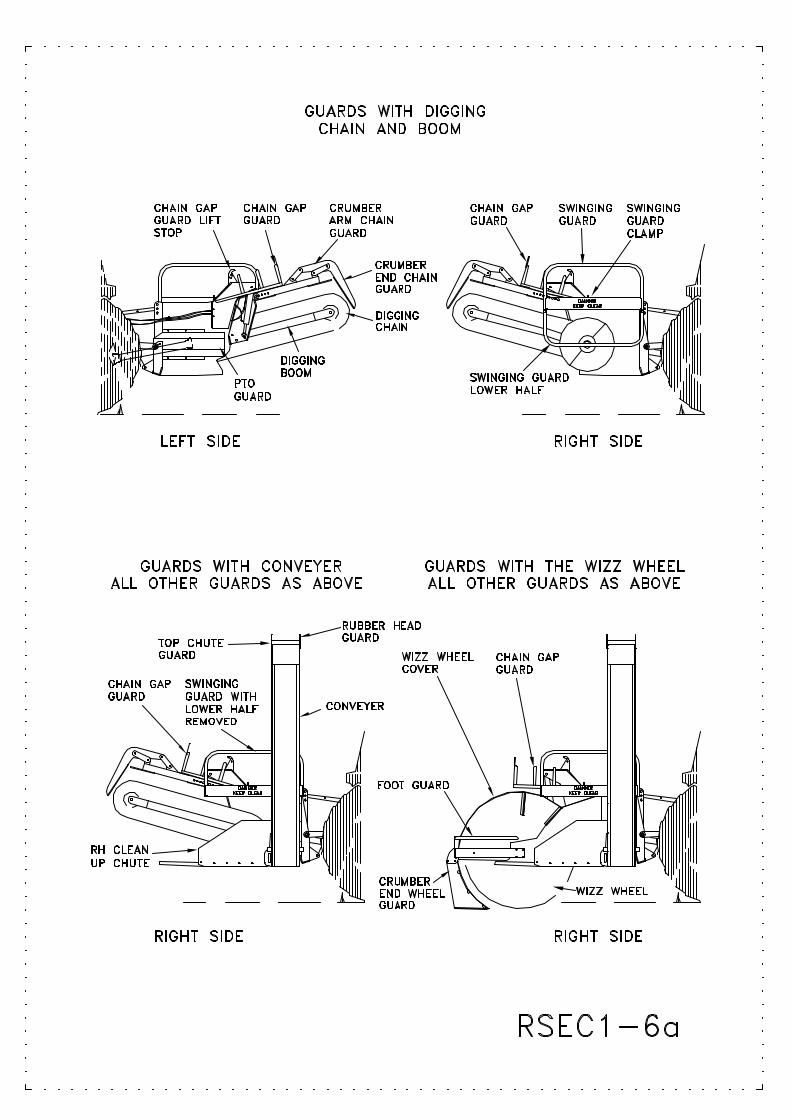
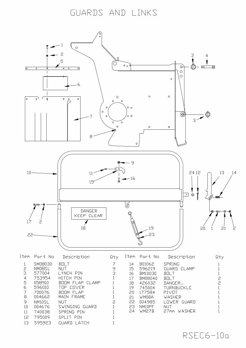
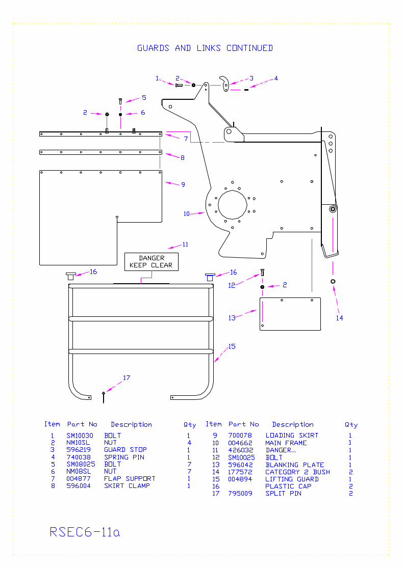
3. WARNING: All guards must be in position and secure. This is not only for safety. Some of the guards form part of the structure of the trencher and leaving them off will cause damage (See Rsec1-6a). Unless a conveyor is fitted, the swinging guard must have the lower half fitted and must be bolted in place with the guard clamp.
4. If guards are removed for maintenance or the removal of obstructions, they must be replaced before
restarting the tractor. 5. Know how to stop the tractor in an emergency (See section 2 and your tractor manual). 6. Know and understand the function of each control (See Section 2). 7. Read Section 2 on connecting and disconnecting the trencher and tractor. 8. The trencher must be operated only whilst seated on the tractor seat. NEVER climb into the gap
between the tractor and the trencher, climb under the trencher or touch any parts, other than control levers, unless the tractor engine is stopped and the trencher is securely supported.
9. WARNING: If maintenance or repair is to be carried out, upon the trencher, ensure that it is
securely supported and that the tractor engine is stopped. 10. Wear protective gloves and safety boots especially when changing teeth or chains. 11. Wear overalls or clothes that will protect you from dust, created by the trencher especially whilst
working in dry conditions. All loose items such as scarves, ties, long hair etc must be constrained. 12. Wear eye protection at all times and a dust mask if dust is visible in the air. 13. Tests in use indicate noise levels of 95db may be produced, ear protection should be worn. 14. Check hydraulic hoses for chaffing and other damage daily (See section 3). 15. Ensure that all control and safety labels are in good condition and replace if necessary. 16. Many parts of the trencher are designed for a safety purpose, which may not be obvious. Use only
genuine A F T Trenchers Limited replacement parts. 17. Keep the trencher/conveyor/wizz wheel well maintained and regularly tighten all nuts and bolts to
ensure they are not working loose (See Rsec3-3b). RSEC1-3b
MOVING THE TRACTOR AROUND WITH THE TRENCHER FITTED 1. Drive only from the tractor seat. 2. Keep the digging boom or wizz wheel, whichever is fitted, as near to the ground as practical to avoid
any tipping. 3. Allow clearance behind when turning for the digging boom to swing round. 4. NEVER allow other people to ride on the trencher. 5. WARNING: Before moving, other than when trenching, ensure that the high lift conveyor (if
fitted) is lifted back into the transport position, firmly held with the catch, secured with the turnbuckle and that the turnbuckle lock nut is tightened (See Rsec2-5b). It is dangerous to drive the tractor around with the high lift conveyor in the lower ' 'in use'' position and damage is likely to occur.
USING THE TRENCHER – ALL ATTACHMENTS
1. WARNING: BEFORE STARTING make sure anyone watching or working nearby is at a safe distance from the tractor and trencher – a minimum of 5 metres as debris will be thrown out during trenching. If people could stray into the proposed working area, cordon it off.
2. WARNING: NEVER leave the driving seat whilst the engine is running. 3. DO NOT try to operate the trencher by reaching across from the ground 4. DO NOT allow anybody to stand in the trench behind the trencher.
5. WARNING: Take great care when starting the conveyor to ensure that nobody is standing nearby as both soil and stones will be thrown several metres beyond the trencher’s discharge end.
6. WARNING: Check the route along the trench for underground cables and pipes and mark
their position. The trenching machine will break any service that crosses the trench. If working in military areas or on battlefield sites, check for unexploded munitions.
7. Alongside a road where work may interfere with normal traffic, notify the police and put up road
works signs. Mark off an area with traffic cones to give free access all round the trencher and to allow for any spoil which may fall onto the road. Always work with the auger or high lift conveyor (whichever is fitted) pointing towards the verge.
8. Do not run the digging chain, wizz wheel or conveyor except when needed. 9. Do not back the tractor with the digging boom lowered into the ground as this puts very heavy loads
onto the structure of the trencher. 10. WARNING: Before removing or fitting digging chains or teeth see RSec3-5a and before
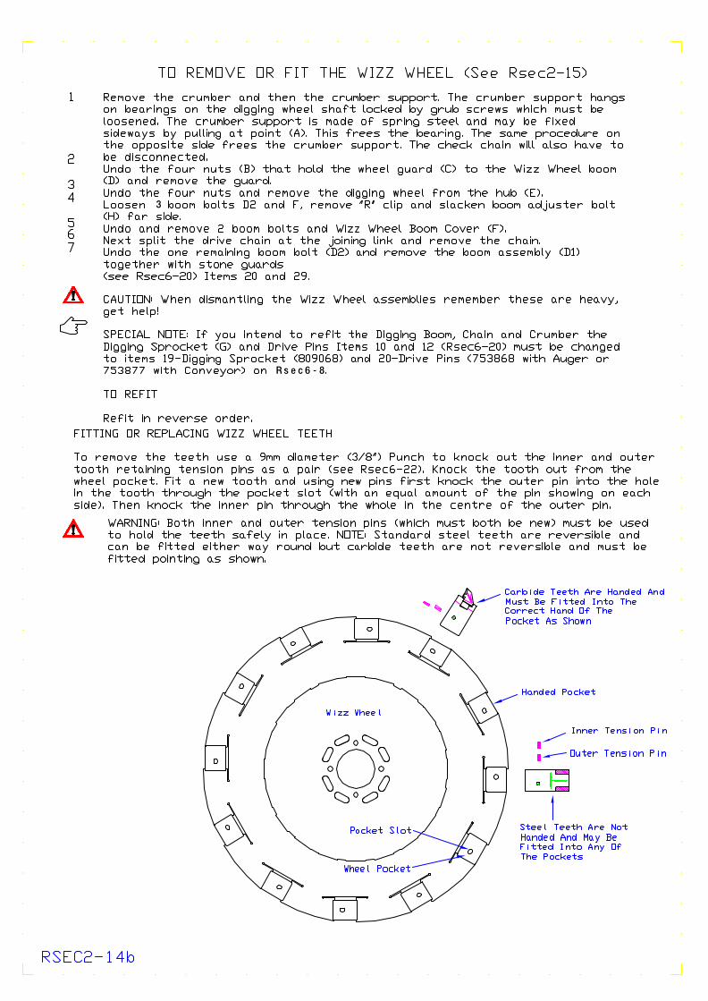
replacing wizz wheel teeth see RSec2-14a. RSEC1-4b
MAKING ADJUSTMENTS OR CLEARING OBSTRUCTIONS 1. WARNING: If it is necessary to adjust or remove obstructions from ANY part,
ALWAYS stop the engine and use the correct tools. Any guards removed must be replaced. 2. All adjustments or repairs should be carried out with the engine stopped and the boom or
wizz wheel on the ground as they may fall if the hydraulics are opened. 3. Do not adjust or remove hydraulic hoses under pressure. 4. Many machine parts are heavy; if necessary, get help to lift them. 5. When handling or removing a digging chain, blades or digging teeth, beware that the chain
can drop and move in unexpected ways. Always release the chain tension before splitting it and avoid handling the chain, except at the ends, as it can double over and nip your hands.
6. WARNING: If it is necessary to raise the swinging guard or if fitted, the high lift
conveyor, ensure that they are firmly held with their catches in the uppermost position and that the high lift conveyor (if fitted) is secured with the turnbuckle.
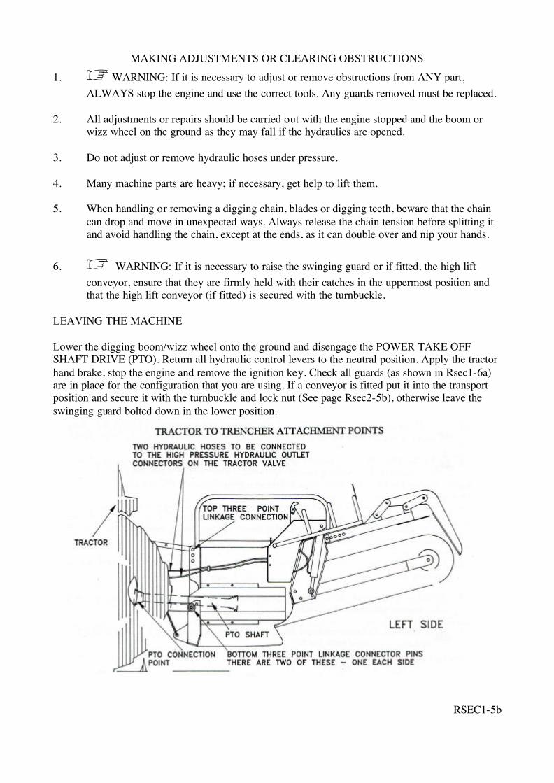
LEAVING THE MACHINE Lower the digging boom/wizz wheel onto the ground and disengage the POWER TAKE OFF SHAFT DRIVE (PTO). Return all hydraulic control levers to the neutral position. Apply the tractor hand brake, stop the engine and remove the ignition key. Check all guards (as shown in Rsec1-6a) are in place for the configuration that you are using. If a conveyor is fitted put it into the transport position and secure it with the turnbuckle and lock nut (See page Rsec2-5b), otherwise leave the swinging guard bolted down in the lower position.
RSEC1-5b
SECTION 2
USES FOR THE TRENCHER
The trencher is used to dig trenches varying from narrow, shallow slits to trenches 1220mm deep and 200mm wide in soil. The soil so dug is moved sideways by the auger so that it does not fall back into the trench or alternatively raised by the high lift conveyor and loaded onto a trailer to be taken away. This is the only use for which the trencher is designed. It is not for digging roads, concrete, rock or any other hard material. It should not be used where there are boulders, which cannot be raised through the width of the trench or where the digging teeth bounce over obstructions in the trench without being able to excavate them. It should not be used where there are cables, pipes or other items under the ground, which may be damaged.
OPERATING THE TRENCHER
This section must be read in conjunction with the relevant tractor operation manual. MOST of the controls are part of the tractor.
RSEC2-1
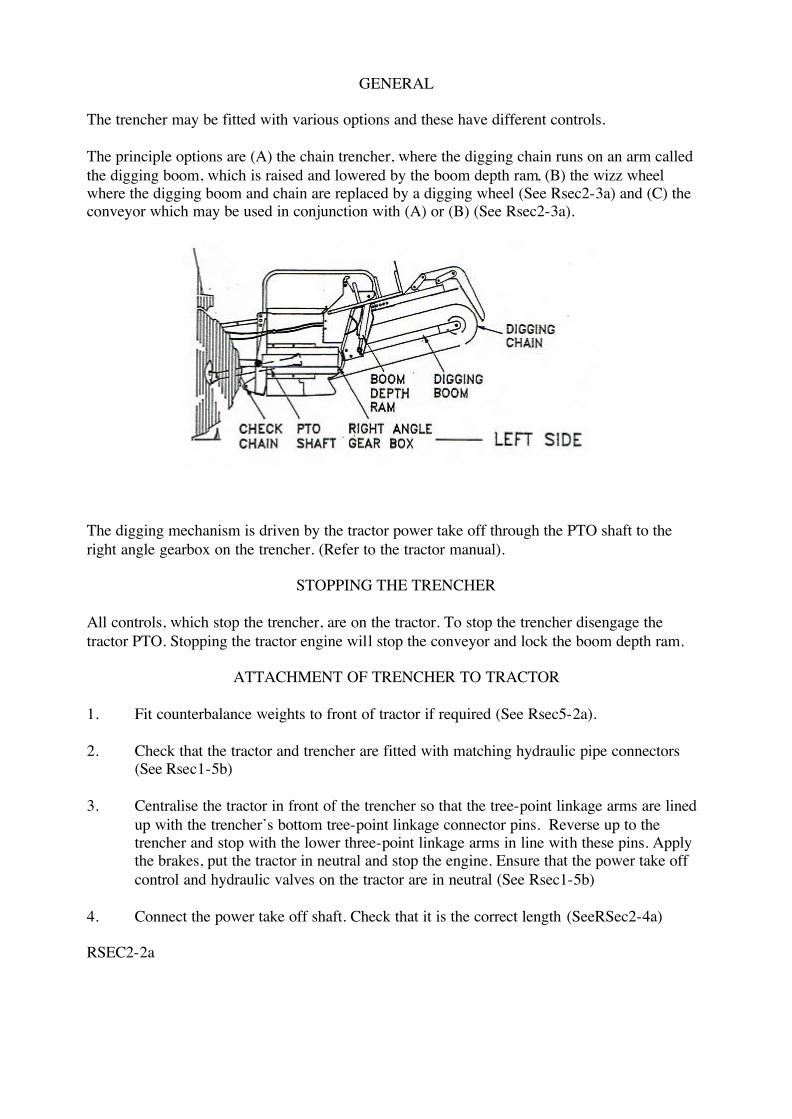
GENERAL
The trencher may be fitted with various options and these have different controls. The principle options are (A) the chain trencher, where the digging chain runs on an arm called the digging boom, which is raised and lowered by the boom depth ram, (B) the wizz wheel where the digging boom and chain are replaced by a digging wheel (See Rsec2-3a) and (C) the conveyor which may be used in conjunction with (A) or (B) (See Rsec2-3a).
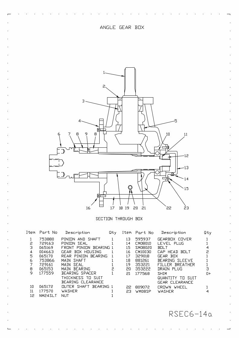
The digging mechanism is driven by the tractor power take off through the PTO shaft to the right angle gearbox on the trencher. (Refer to the tractor manual).
STOPPING THE TRENCHER
All controls, which stop the trencher, are on the tractor. To stop the trencher disengage the tractor PTO. Stopping the tractor engine will stop the conveyor and lock the boom depth ram.
ATTACHMENT OF TRENCHER TO TRACTOR
1. Fit counterbalance weights to front of tractor if required (See Rsec5-2a). 2. Check that the tractor and trencher are fitted with matching hydraulic pipe connectors
(See Rsec1-5b) 3. Centralise the tractor in front of the trencher so that the tree-point linkage arms are lined
up with the trencher’s bottom tree-point linkage connector pins. Reverse up to the trencher and stop with the lower three-point linkage arms in line with these pins. Apply the brakes, put the tractor in neutral and stop the engine. Ensure that the power take off control and hydraulic valves on the tractor are in neutral (See Rsec1-5b)
4. Connect the power take off shaft. Check that it is the correct length (SeeRSec2-4a) RSEC2-2a
5. Connect the two lower three-point linkage arms and the single, top three-point linkage arm. Lock
them in position with the pins provided with the tractor (See RSec1-5b). 6. Connect the hydraulic hoses to the tractor hydraulics valve outlet (See Rsec1-5b). NOTE: a) If no conveyor is fitted to the trencher, the tractor valve will operate the raising and lowering of
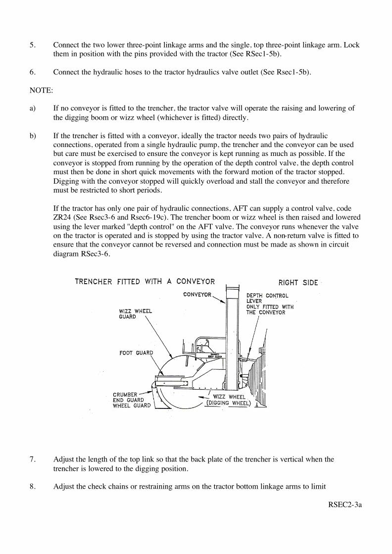
the digging boom or wizz wheel (whichever is fitted) directly. b) If the trencher is fitted with a conveyor, ideally the tractor needs two pairs of hydraulic
connections, operated from a single hydraulic pump, the trencher and the conveyor can be used but care must be exercised to ensure the conveyor is kept running as much as possible. If the conveyor is stopped from running by the operation of the depth control valve, the depth control must then be done in short quick movements with the forward motion of the tractor stopped. Digging with the conveyor stopped will quickly overload and stall the conveyor and therefore must be restricted to short periods.
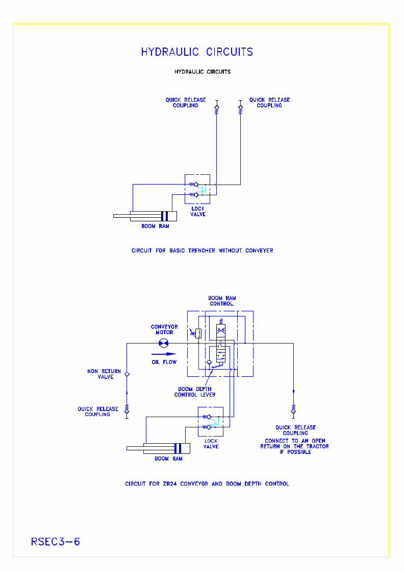
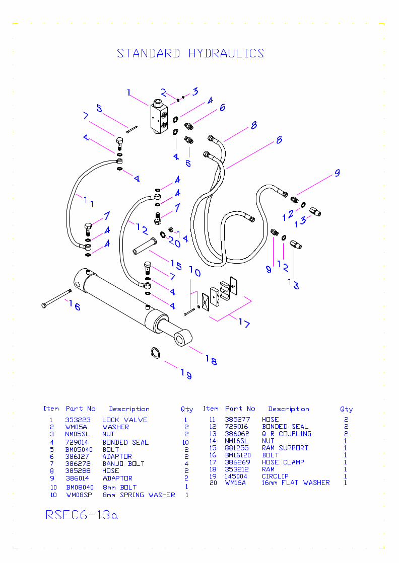
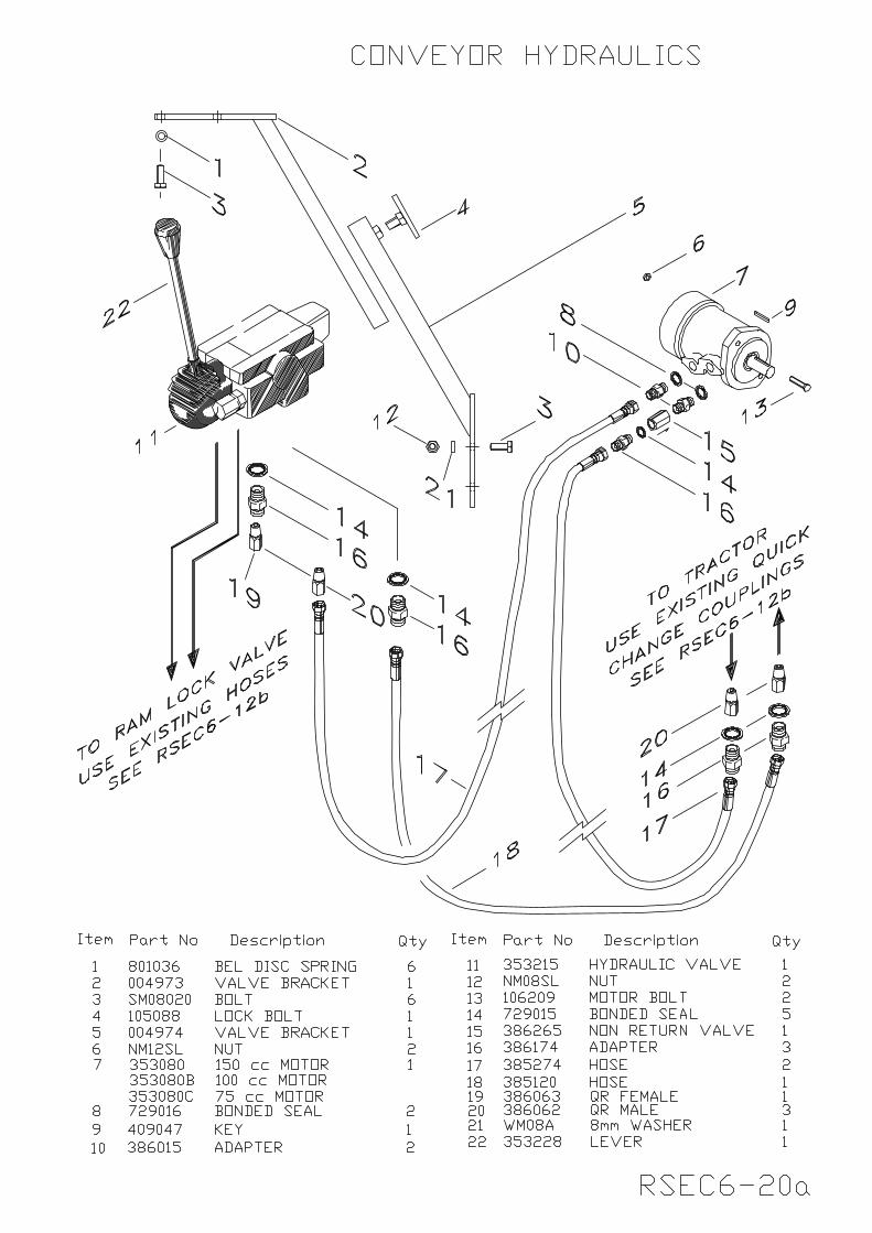
If the tractor has only one pair of hydraulic connections, AFT can supply a control valve, code ZR24 (See Rsec3-6 and Rsec6-19c). The trencher boom or wizz wheel is then raised and lowered using the lever marked ''depth control'' on the AFT valve. The conveyor runs whenever the valve on the tractor is operated and is stopped by using the tractor valve. A non-return valve is fitted to ensure that the conveyor cannot be reversed and connection must be made as shown in circuit diagram RSec3-6.
7. Adjust the length of the top link so that the back plate of the trencher is vertical when the
trencher is lowered to the digging position. 8. Adjust the check chains or restraining arms on the tractor bottom linkage arms to limit
RSEC2-3a
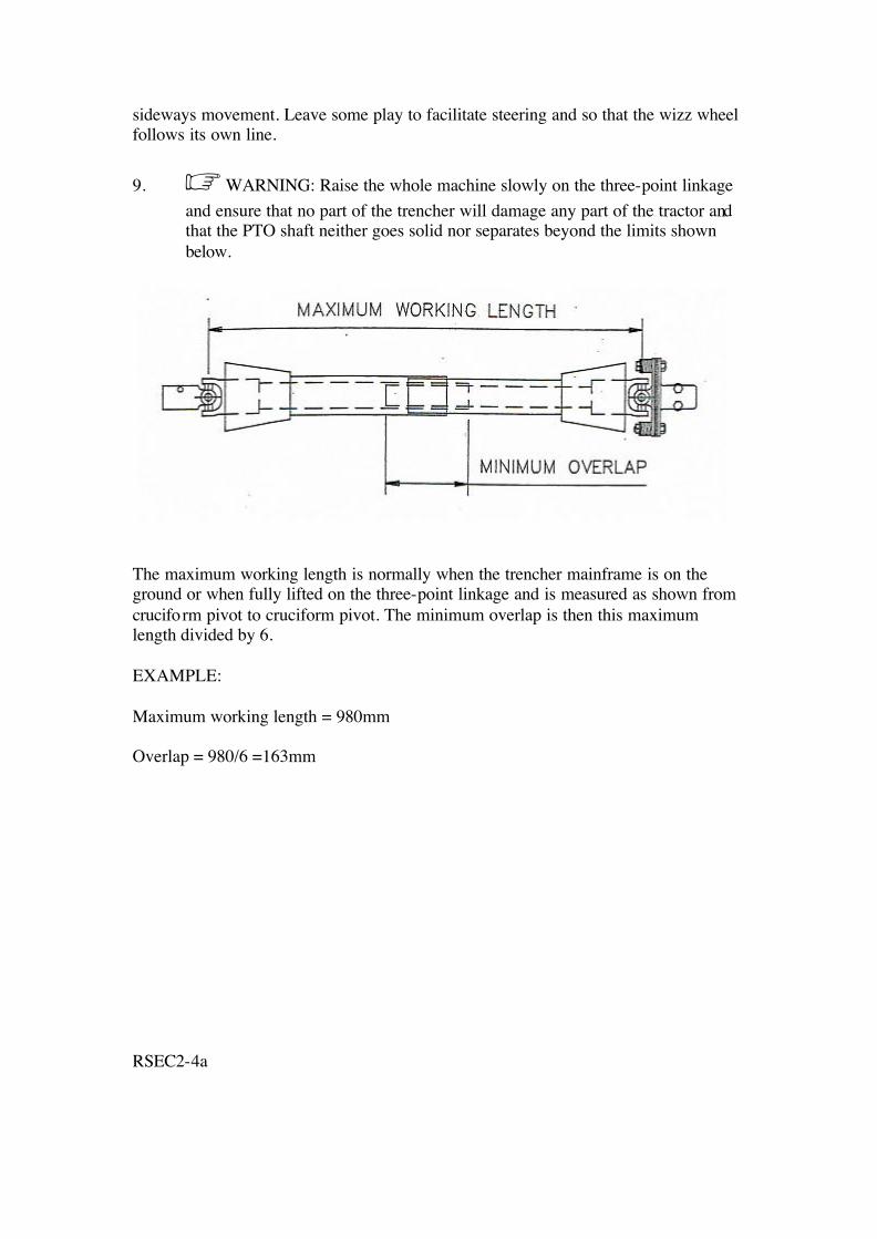
sideways movement. Leave some play to facilitate steering and so that the wizz wheel follows its own line. 9. WARNING: Raise the whole machine slowly on the three-point linkage
and ensure that no part of the trencher will damage any part of the tractor and that the PTO shaft neither goes solid nor separates beyond the limits shown below.
The maximum working length is normally when the trencher mainframe is on the ground or when fully lifted on the three-point linkage and is measured as shown from cruciform pivot to cruciform pivot. The minimum overlap is then this maximum length divided by 6. EXAMPLE: Maximum working length = 980mm Overlap = 980/6 =163mm RSEC2-4a
REMOVING THE TRENCHER FROM THE TRACTOR
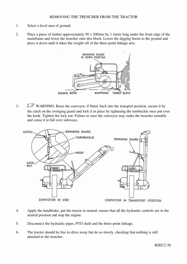
1. Select a level area of ground. 2. Place a piece of timber approximately 50 x 200mm by 1 metre long under the front edge of the
mainframe and lower the trencher onto this block. Lower the digging boom to the ground and press it down until it takes the weight off of the three-point linkage arm.
3. WARNING: Raise the conveyor, if fitted, back into the transport position, secure it by the catch on the swinging guard and lock it in place by tightening the turnbuckle once put over the hook. Tighten the lock nut. Failure to raise the conveyor may make the trencher unstable and cause it to fall over sideways.
4. Apply the handbrake, put the tractor in neutral, ensure that all the hydraulic controls are in the
neutral position and stop the engine. 5. Disconnect the hydraulic pipes, PTO shaft and the three-point linkage. 6. The tractor should be free to drive away but do so slowly, checking that nothing is still
attached to the trencher.
RSEC2-5b
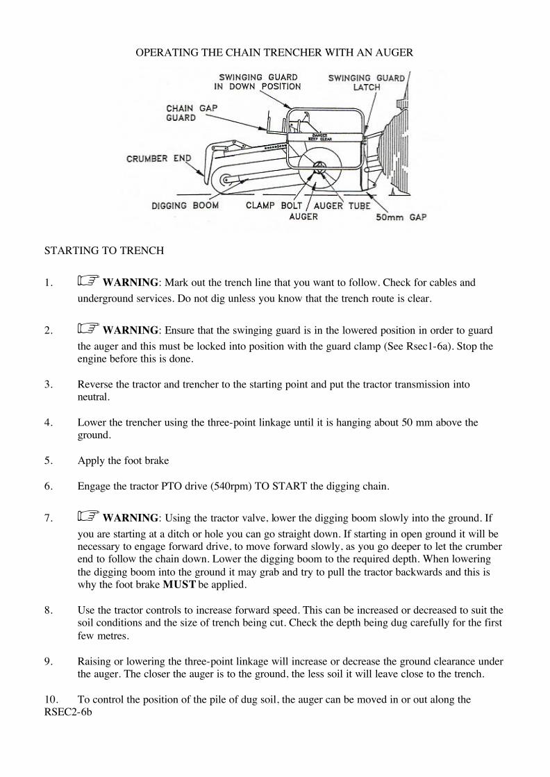
OPERATING THE CHAIN TRENCHER WITH AN AUGER
STARTING TO TRENCH 1. WARNING: Mark out the trench line that you want to follow. Check for cables and
underground services. Do not dig unless you know that the trench route is clear.
2. WARNING: Ensure that the swinging guard is in the lowered position in order to guard the auger and this must be locked into position with the guard clamp (See Rsec1-6a). Stop the engine before this is done.
3. Reverse the tractor and trencher to the starting point and put the tractor transmission into
neutral. 4. Lower the trencher using the three-point linkage until it is hanging about 50 mm above the
ground. 5. Apply the foot brake 6. Engage the tractor PTO drive (540rpm) TO START the digging chain.
7. WARNING: Using the tractor valve, lower the digging boom slowly into the ground. If you are starting at a ditch or hole you can go straight down. If starting in open ground it will be necessary to engage forward drive, to move forward slowly, as you go deeper to let the crumber end to follow the chain down. Lower the digging boom to the required depth. When lowering the digging boom into the ground it may grab and try to pull the tractor backwards and this is why the foot brake MUST be applied.
8. Use the tractor controls to increase forward speed. This can be increased or decreased to suit the
soil conditions and the size of trench being cut. Check the depth being dug carefully for the first few metres.
9. Raising or lowering the three-point linkage will increase or decrease the ground clearance under
the auger. The closer the auger is to the ground, the less soil it will leave close to the trench. 10. To control the position of the pile of dug soil, the auger can be moved in or out along the RSEC2-6b
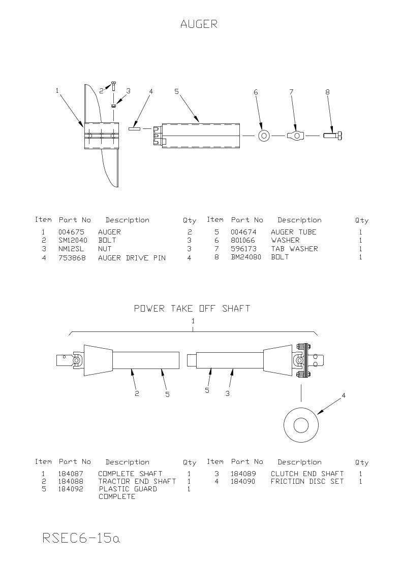
auger tube and either one or two augers fitted. To move or remove an auger, loosen the clamp bolts and slide the auger along the auger tube to the required position, but do not fit an auger so that it overlaps the end of the auger tube. Re-tighten the clamp bolts. Ensure the tractor engine is switched off before making any such adjustments (See Rsec2-6b).
STOPPING TRENCHING
1. WARNING: Raise the digging boom clear of the ground and disengage the PTO drive at once. It is dangerous to continue driving the trenching chain once it is clear of the ground.
2. Raise the trencher on the three-point linkage to give more ground clearance.
The normal tractor transmission can now be re-engaged and used to manoeuvre to the next trench.
RSEC2-7
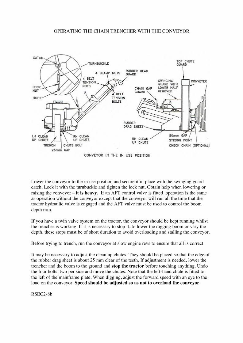
OPERATING THE CHAIN TRENCHER WITH THE CONVEYOR
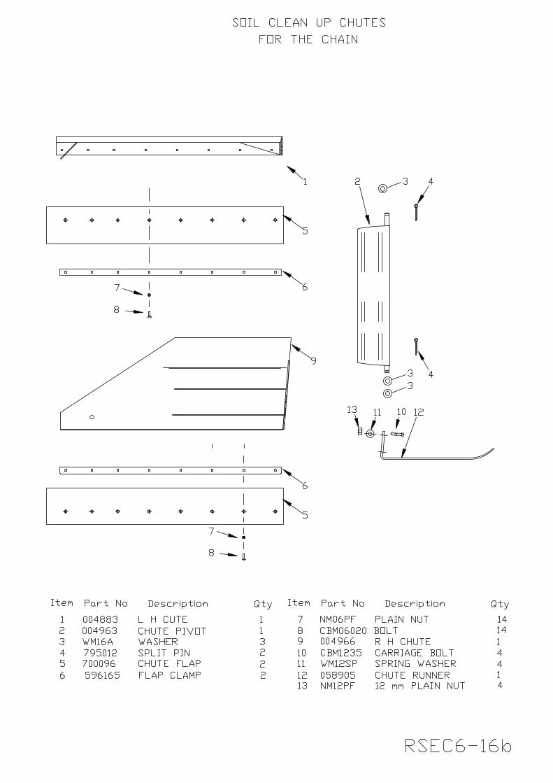
Lower the conveyor to the in use position and secure it in place with the swinging guard catch. Lock it with the turnbuckle and tighten the lock nut. Obtain help when lowering or raising the conveyor – it is heavy. If an AFT control valve is fitted, operation is the same as operation without the conveyor except that the conveyor will run all the time that the tractor hydraulic valve is engaged and the AFT valve must be used to control the boom depth ram. If you have a twin valve system on the tractor, the conveyor should be kept running whilst the trencher is working. If it is necessary to stop it, to lower the digging boom or vary the depth, these stops must be of short duration to avoid overloading and stalling the conveyor. Before trying to trench, run the conveyor at slow engine revs to ensure that all is correct. It may be necessary to adjust the clean up chutes. They should be placed so that the edge of the rubber drag sheet is about 25 mm clear of the teeth. If adjustment is needed, lower the trencher and the boom to the ground and stop the tractor before touching anything. Undo the four bolts, two per side and move the chutes. Note that the left-hand chute is fitted to the left of the mainframe plate. When digging, adjust the forward speed with an eye to the load on the conveyor. Speed should be adjusted so as not to overload the conveyor. RSEC2-8b
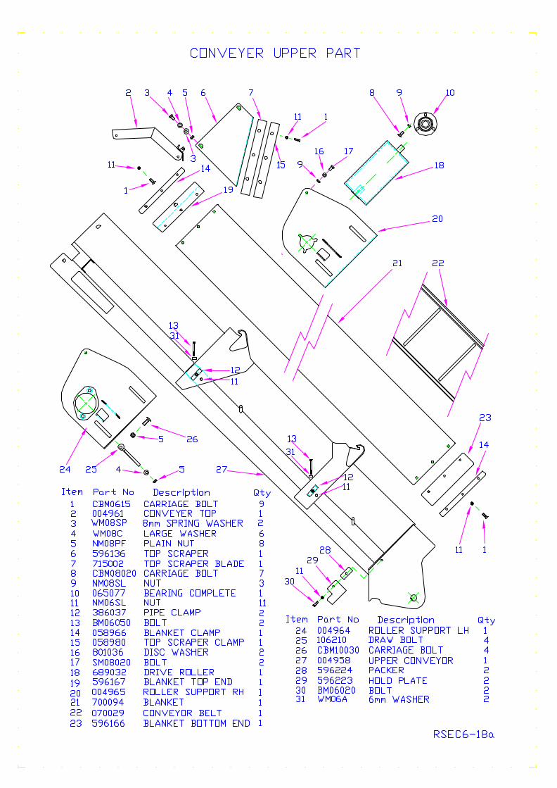
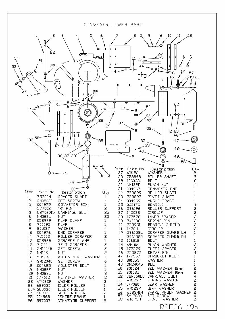
It is most important that the soil collection trailer does not run into the conveyor, as this may cause damage. Furthermore, do not back the trencher with the clean up chutes close to the ground as they may dig in and be bent. NOTE: The top roller drives the conveyor and for this drive to work effectively the belt tension must be kept correct. The belt is adjusted by four tension bolts at the motor end of the conveyor. In order to adjust the belt, loosen the four M10 clamp nuts, which hold the roller and motor support plates and tighten the four tension nuts evenly on the tension bolts. Tension is correct when, with the conveyor in the in use position, pulling hard on a flight at point A, the belt can be raised so that the flight just reaches the top edge of the conveyor box. ALWAYS switch off the tractor engine before making any sort of adjustment. Do not over tighten the belt otherwise excessive wear may be caused.
WARNING: Do not run the conveyor if anyone is within range of its discharge. They should be at least 5 metres away. Anyone working on a dumper or tractor collecting soil should be protected from the discharge and wear eye protection at all times. If conditions are dusty, in that airborne dust is clearly visible, a suitable breathing mask should also be worn. If the three-point linkage sinks whilst working, a check chain may be fitted from the strong point (See Rsec2-8b) on the front of the trencher mainframe to a suitable point, as nearly vertical as possible, on the tractor. The conveyor should not be dragged along the ground as this may cause damage.
RSEC2-9b
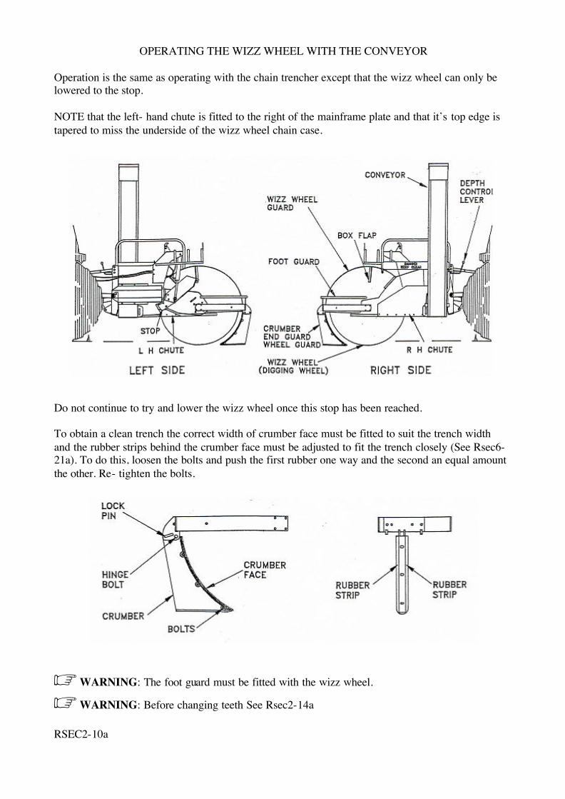
OPERATING THE WIZZ WHEEL WITH THE CONVEYOR
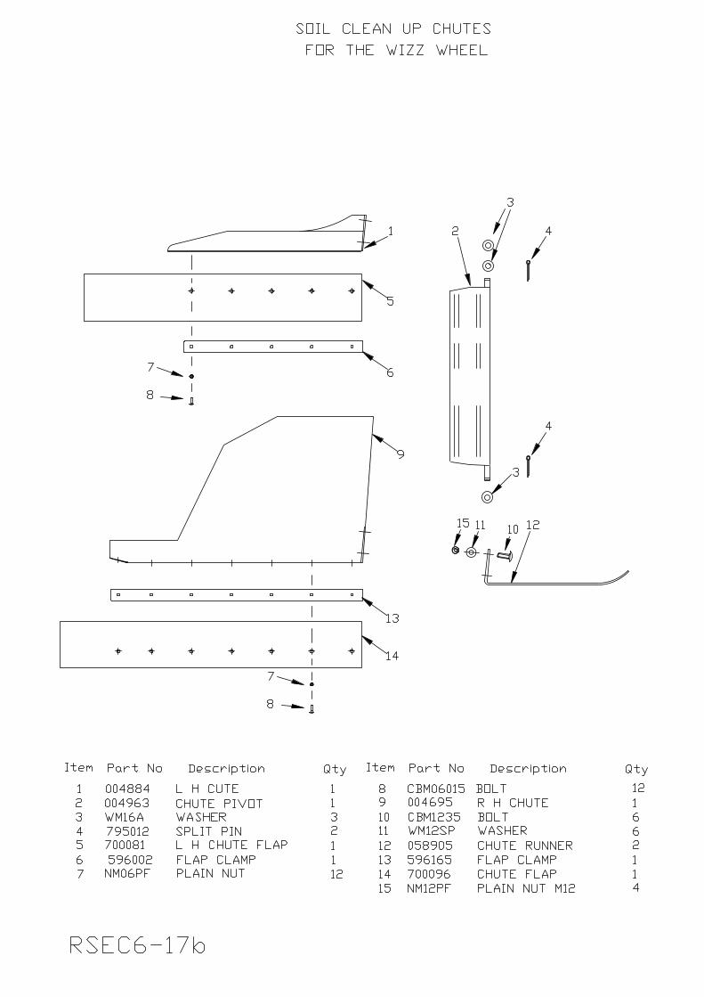
Operation is the same as operating with the chain trencher except that the wizz wheel can only be lowered to the stop. NOTE that the left- hand chute is fitted to the right of the mainframe plate and that it’s top edge is tapered to miss the underside of the wizz wheel chain case.
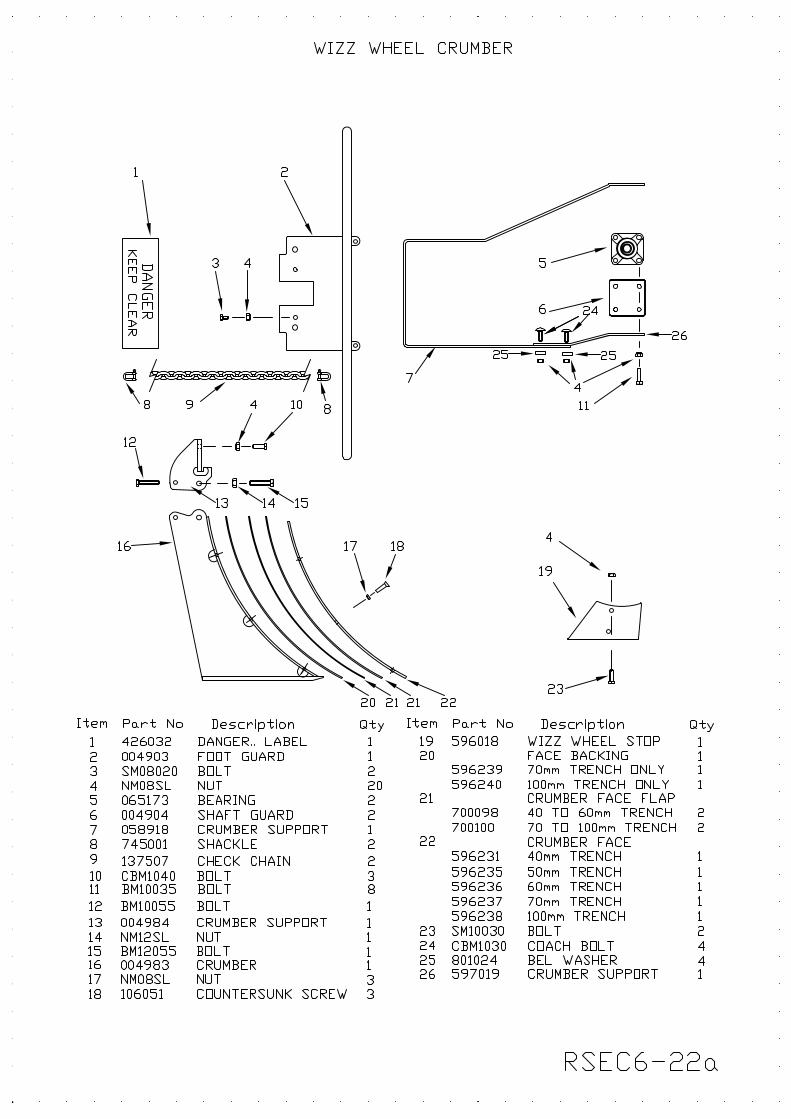
Do not continue to try and lower the wizz wheel once this stop has been reached. To obtain a clean trench the correct width of crumber face must be fitted to suit the trench width and the rubber strips behind the crumber face must be adjusted to fit the trench closely (See Rsec6-21a). To do this, loosen the bolts and push the first rubber one way and the second an equal amount the other. Re- tighten the bolts.
WARNING: The foot guard must be fitted with the wizz wheel.
WARNING: Before changing teeth See Rsec2-14a RSEC2-10a
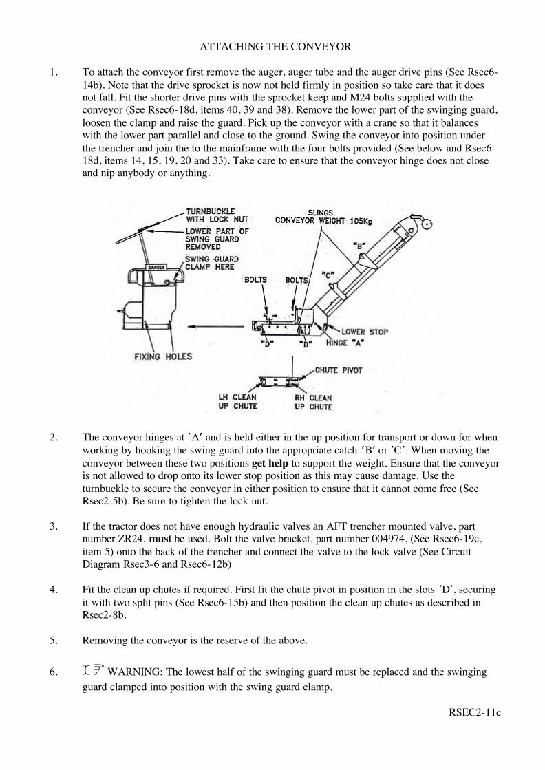
ATTACHING THE CONVEYOR
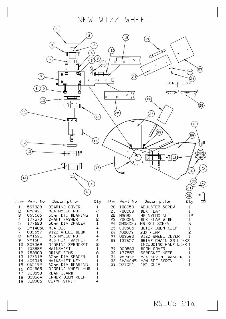
1. To attach the conveyor first remove the auger, auger tube and the auger drive pins (See Rsec6-14b). Note that the drive sprocket is now not held firmly in position so take care that it does not fall. Fit the shorter drive pins with the sprocket keep and M24 bolts supplied with the conveyor (See Rsec6-18d, items 40, 39 and 38). Remove the lower part of the swinging guard, loosen the clamp and raise the guard. Pick up the conveyor with a crane so that it balances with the lower part parallel and close to the ground. Swing the conveyor into position under the trencher and join the to the mainframe with the four bolts provided (See below and Rsec6-18d, items 14, 15, 19, 20 and 33). Take care to ensure that the conveyor hinge does not close and nip anybody or anything.
2. The conveyor hinges at A and is held either in the up position for transport or down for when
working by hooking the swing guard into the appropriate catch B or C. When moving the conveyor between these two positions get help to support the weight. Ensure that the conveyor is not allowed to drop onto its lower stop position as this may cause damage. Use the turnbuckle to secure the conveyor in either position to ensure that it cannot come free (See Rsec2-5b). Be sure to tighten the lock nut.
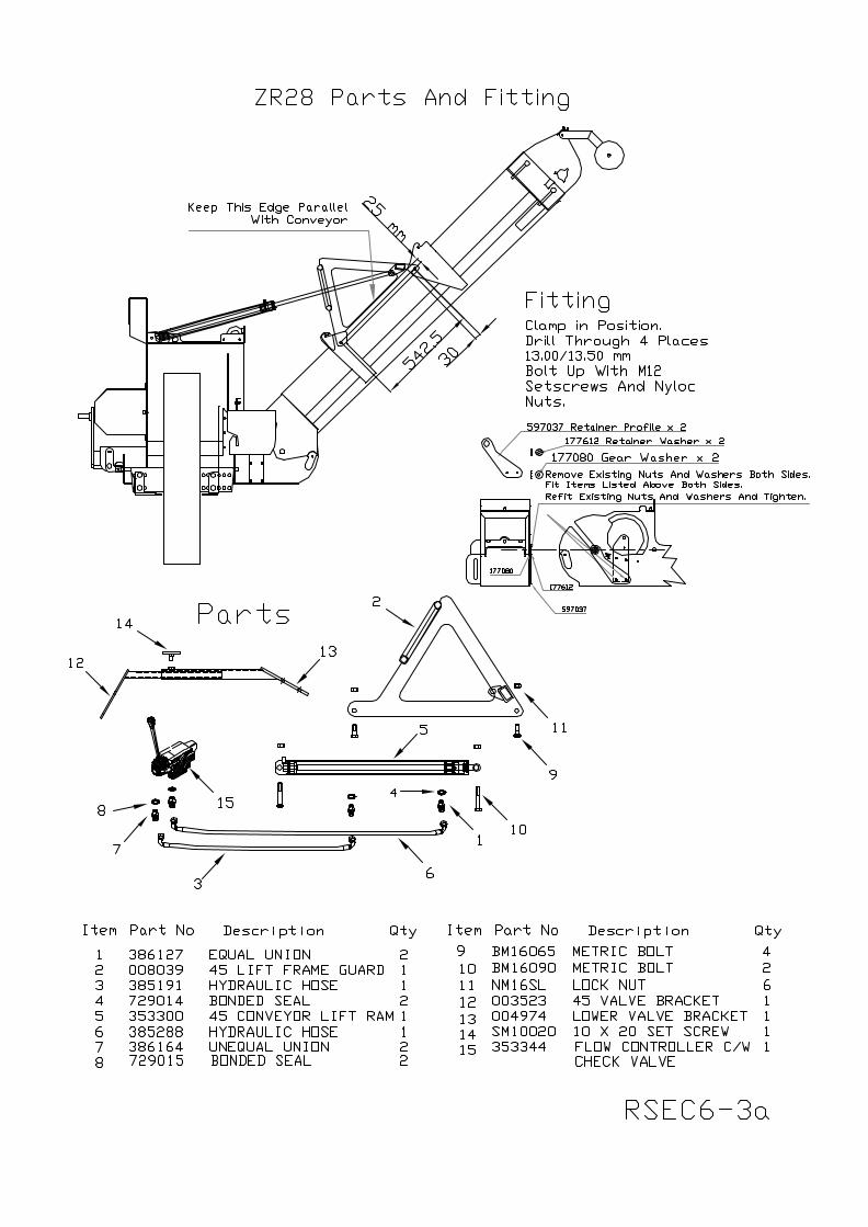
3. If the tractor does not have enough hydraulic valves an AFT trencher mounted valve, part
number ZR24, must be used. Bolt the valve bracket, part number 004974, (See Rsec6-19c, item 5) onto the back of the trencher and connect the valve to the lock valve (See Circuit Diagram Rsec3-6 and Rsec6-12b)
4. Fit the clean up chutes if required. First fit the chute pivot in position in the slots D, securing
it with two split pins (See Rsec6-15b) and then position the clean up chutes as described in Rsec2-8b.
5. Removing the conveyor is the reserve of the above.
6. WARNING: The lowest half of the swinging guard must be replaced and the swinging guard clamped into position with the swing guard clamp.
RSEC2-11c
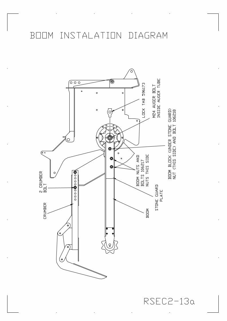
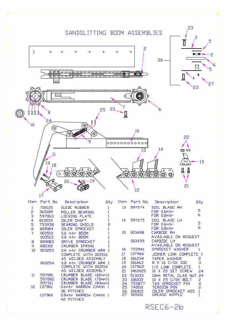
CHANGING THE CHAIN ASSEMBLY AND THE WIZZ WHEEL
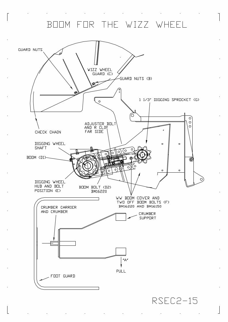
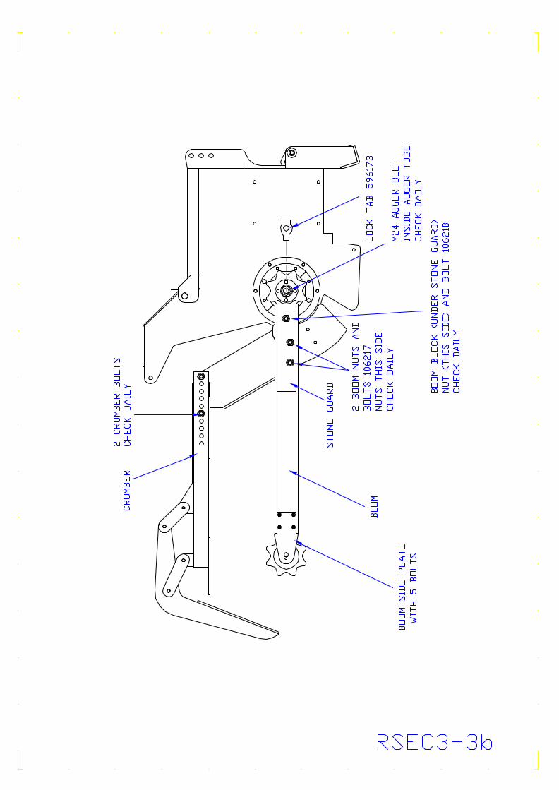
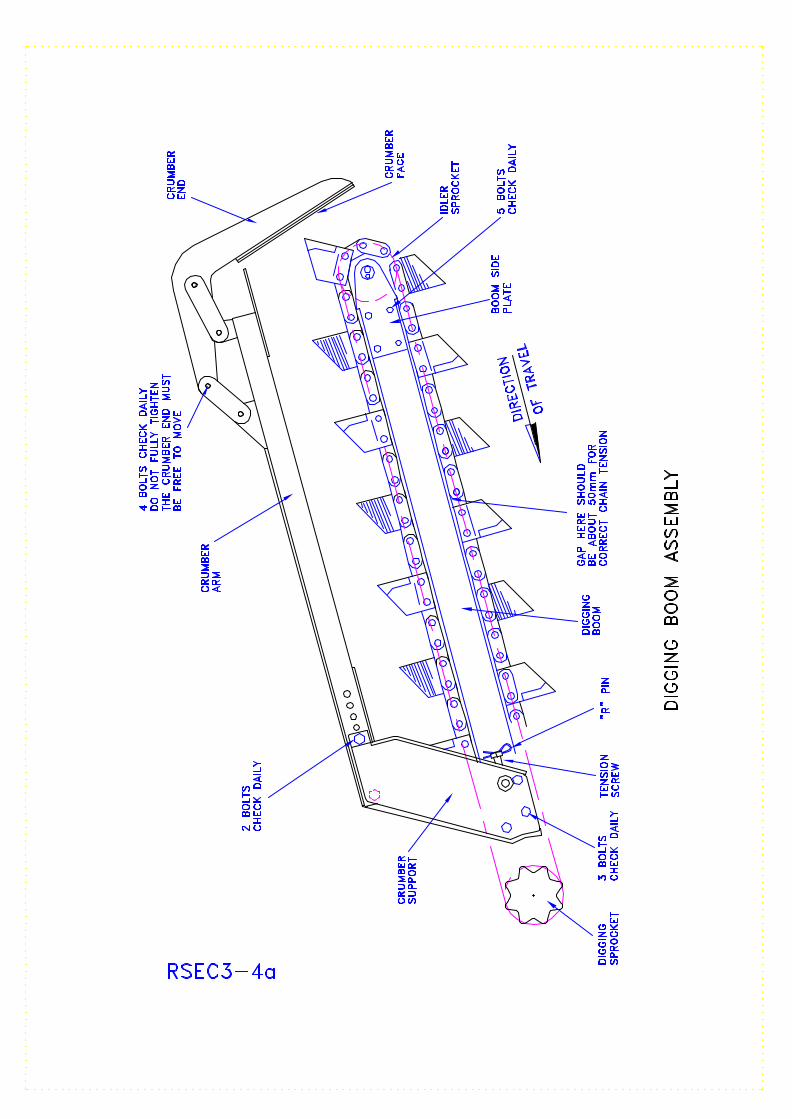
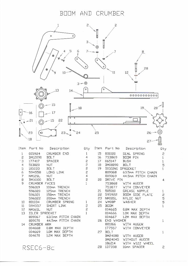
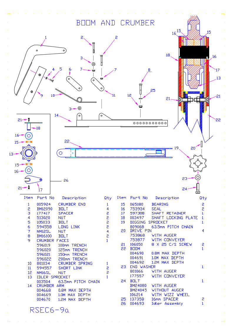
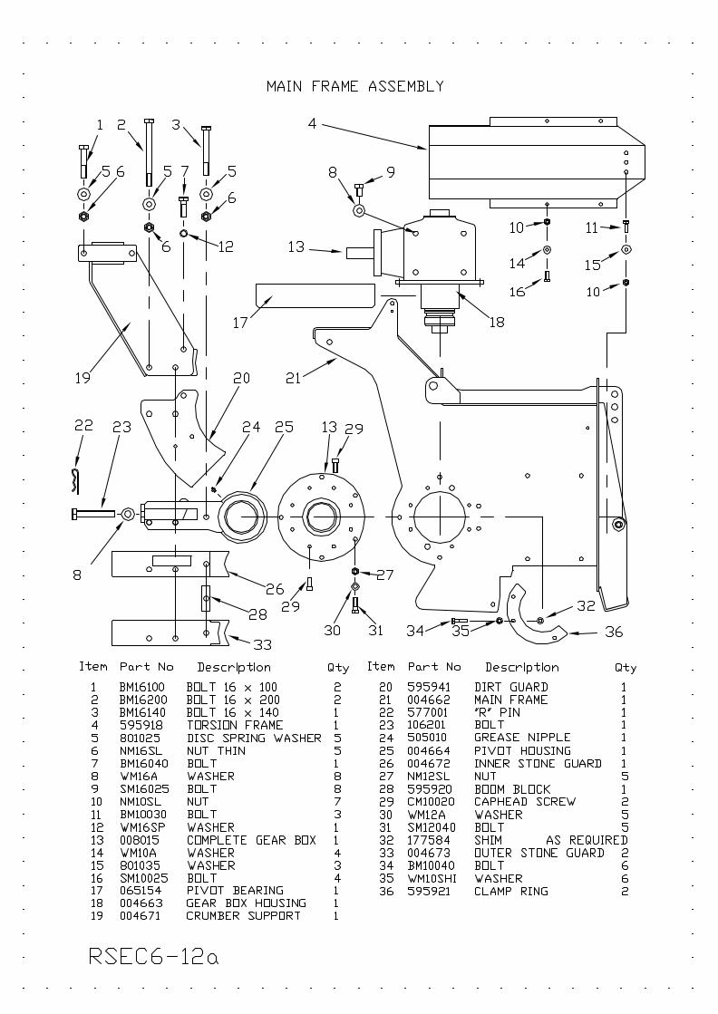
The boom and chain or wizz wheel, whichever is fitted, are heavy. Help or lifting equipment to lift them is essential. First remove the right-hand clean up chute (See Rsec2-11c), if fitted. Do not remove the auger. TO REMOVE THE BOOM AND CHAIN (See Rsec2-13a) Lower the boom until the teeth are just clear of the ground. Slacken the three nuts on the bolts (See Rsec2-13a, part numbers 106217 and 106218). Remove the R pin (See Rsec3-4a) which locks the tension screw and turn it to slacken the chain. Split the chain by removing one tooth or side plate (depending on chain type) (SeeRSec2-13a, parts numbers 106217 and 106218), which hold the boom in place and remove the boom, complete with adjuster screw. Remove the two stone guard plates and the boom block with its bolt. Leave the main bolts in place and retain the bolt (from the boom block) and the tree nuts for use later. Undo the two crumber bolts and remove them. Put all loose bolts back into their respective holes and loosely put on the nuts for safekeeping. TO REMOVE THE AUGER (See Rsec2-13a) WARNING: If an auger is fitted, knock back the locking tab (596173), undo the M24 bolt (at the bottom of the auger tube) and pull the auger free. Note that the auger should be removed after the chain because its removal frees the drive sprocket which, with the weight of the chain, may fall unexpectedly. REFITTING (See Rsec2-13a) Re-fitting the boom, chain and auger is the reverse of the above. The bolts (106217) and (106218) must be fitted the correct way round and MUST be genuine AFT Trenchers Limited parts. They are not simple bolts. Also, care should be taken to ensure that the auger locking tab (596173) is formed firmly around the M24 auger bolt. TENSIONING THE DIGGING CHAIN Tighten the chain tension screw (See Rsec3-4a) until the gap between the chain and the boom at the underside of the boom is about 70 mm. Run the digging chain for a few seconds to ensure free running, then recheck the adjustment. Replace the R pin.
RSEC2-12a
3
R s e c 6 - 8
SECTION 3
ROUTINE SERVICING
Lubrication Chart
Maintenance Schedule Maintenance Procedure
Circuit Diagram
LUBRICANT RECOMMENDATIONS:
Bevel Gearbox: SAE90/140 Grease – High melting point, general purpose, lithium based.
RSEC3-1
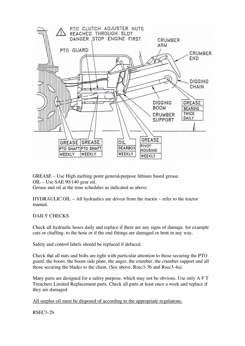
GREASE – Use High melting point general-purpose lithium based grease. OIL – Use SAE 90/140 gear oil. Grease and oil at the time schedules as indicated as above. HYDRAULIC OIL – All hydraulics are driven from the tractor – refer to the tractor manual. DAILY CHECKS Check all hydraulic hoses daily and replace if there are any signs of damage, for example cuts or chaffing, to the hose or if the end fittings are damaged or bent in any way. Safety and control labels should be replaced if defaced. Check that all nuts and bolts are tight with particular attention to those securing the PTO guard, the boom, the boom side plate, the auger, the crumber, the crumber support and all those securing the blades to the chain. (See above, Rsec3-3b and Rsec3-4a). Many parts are designed for a safety purpose, which may not be obvious. Use only A F T Trenchers Limited Replacement parts. Check all parts at least once a week and replace if they are damaged All surplus oil must be disposed of according to the appropriate regulations. RSEC3-2b
MAINTENANCE PROCEDURE
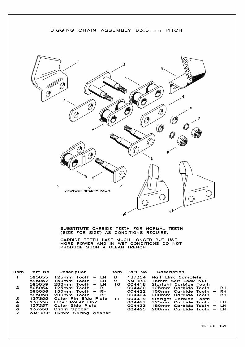
GENERAL Lubrication, checking bolts for tightness and boom/chain/teeth maintenance are the most frequently required; but all parts of a trenching machine are subjected to heavy loads and should be inspected at least weekly and replaced if damaged. DIGGING BOOM ASSEMBLY The digging chain and all the digging boom components on which it runs, work underground and are subject to wear. They should be inspected regularly and all damaged or very worn parts should be replaced. DIGGING CHAIN AND TEETH Worn teeth greatly reduce the digging efficiency and should be replaced. When working, heavy and uneven loads are applied to the chain rollers. Inspection will show greater wear on the roller and side plates under each tooth’s rear edge. To achieve maximum life expectancy from digging chain, it is recommended that, when replacing teeth, as far as possible (whilst still keeping the teeth pattern) the teeth are fitted to the lesser-worn parts of the chain. It is a good idea to remove the chain from the boom, remove all teeth and turn the chain round end for end and turn it over, fitting the teeth as previously. All teeth simply bolt on to the chain but always check that the nuts securing them are tight. IMPORTANT: The leading (cutting) edge of the teeth is the widest part, which then tapers back. When fitting the chain to the boom or new teeth to the chain, fit them this way round. The fitting of teeth the wrong way round is a common fault in trenching operations. The 44.5mm pitch digging chain can be fitted with four widths of tooth; 100mm, 125mm, 150mm and 200mm. The 63.5mm pitch digging chain can be fitted with three widths of tooth; 125mm, 150mm and 200mm. For the correct tooth layout, refer to the digging chain assembly sequence charts (See Rsec6-2 to Rsec6-7). Digging chain length can be lengthened or shortened to suit all boom lengths my adding or removing the appropriate number of links. CHANGING TEETH AND REMOVING THE DIGGING CHAIN See above and also refer to RSec2-12a CHANGING THE WIZZ WHEEL TEETH Refer to RSec2-14a TORQUE OF THE PTO CLUTCH WARNING: Adjustments to the PTO clutch must only be made when the trencher is disconnected from the tractor. It is dangerous to touch the adjustment nuts if there is a chance that the PTO shaft may turn under power. The PTO clutch is to protect your tractor and you should set it accordingly. Tighten or loosen (See Rsec3-2a) the nuts (reachable through the slot) as required. All nuts on the clutch should be turned the same amount. It will be necessary to turn the PTO and this can be done by hand.
RSEC3-5a

SECTION 4
FAULT DIAGNOSIS
RSEC4-1
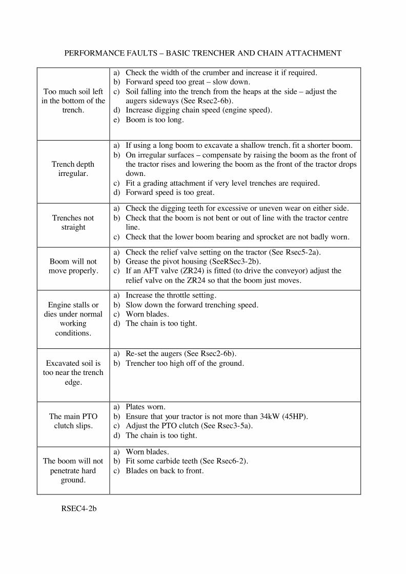
PERFORMANCE FAULTS – BASIC TRENCHER AND CHAIN ATTACHMENT
Too much soil left in the bottom of the
trench.
a) Check the width of the crumber and increase it if required. b) Forward speed too great – slow down. c) Soil falling into the trench from the heaps at the side – adjust the
augers sideways (See Rsec2-6b). d) Increase digging chain speed (engine speed). e) Boom is too long.
Trench depth irregular.
a) If using a long boom to excavate a shallow trench, fit a shorter boom. b) On irregular surfaces – compensate by raising the boom as the front of
the tractor rises and lowering the boom as the front of the tractor drops down.
c) Fit a grading attachment if very level trenches are required. d) Forward speed is too great.
Trenches not
straight
a) Check the digging teeth for excessive or uneven wear on either side. b) Check that the boom is not bent or out of line with the tractor centre
line. c) Check that the lower boom bearing and sprocket are not badly worn.
Boom will not move properly.
a) Check the relief valve setting on the tractor (See Rsec5-2a). b) Grease the pivot housing (SeeRSec3-2b). c) If an AFT valve (ZR24) is fitted (to drive the conveyor) adjust the
relief valve on the ZR24 so that the boom just moves.
Engine stalls or
dies under normal working
conditions.
a) Increase the throttle setting. b) Slow down the forward trenching speed. c) Worn blades. d) The chain is too tight.
Excavated soil is
too near the trench edge.
a) Re-set the augers (See Rsec2-6b). b) Trencher too high off of the ground.
The main PTO
clutch slips.
a) Plates worn. b) Ensure that your tractor is not more than 34kW (45HP). c) Adjust the PTO clutch (See Rsec3-5a). d) The chain is too tight.
The boom will not
penetrate hard ground.
a) Worn blades. b) Fit some carbide teeth (See Rsec6-2). c) Blades on back to front.
RSEC4-2b
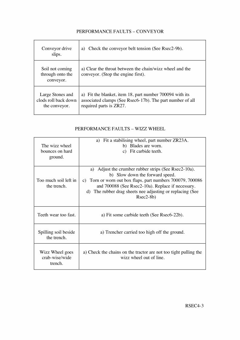
PERFORMANCE FAULTS – CONVEYOR
Conveyor drive
slips.
a) Check the conveyor belt tension (See Rsec2-9b).
Soil not coming through onto the
conveyor.
a) Clear the throat between the chain/wizz wheel and the conveyor. (Stop the engine first).
Large Stones and
clods roll back down the conveyor.
a) Fit the blanket, item 18, part number 700094 with its associated clamps (See Rsec6-17b). The part number of all required parts is ZR27.
PERFORMANCE FAULTS – WIZZ WHEEL
The wizz wheel bounces on hard
ground.
a) Fit a stabilising wheel, part number ZR23A. b) Blades are worn. c) Fit carbide teeth.
Too much soil left in the trench.
a) Adjust the crumber rubber strips (See Rsec2-10a). b) Slow down the forward speed.
c) Torn or worn out box flaps, part numbers 700079, 700086 and 700088 (See Rsec2-10a). Replace if necessary.
d) The rubber drag sheets nee adjusting or replacing (See Rsec2-8b)
Teeth wear too fast.
a) Fit some carbide teeth (See Rsec6-22b).
Spilling soil beside
the trench.
a) Trencher carried too high off the ground.
Wizz Wheel goes crab-wise/wide
trench.
a) Check the chains on the tractor are not too tight pulling the
wizz wheel out of line.
RSEC4-3

SECTION 5
SPECIFICATION OF THE 45 TRENCHER
RSEC5-1
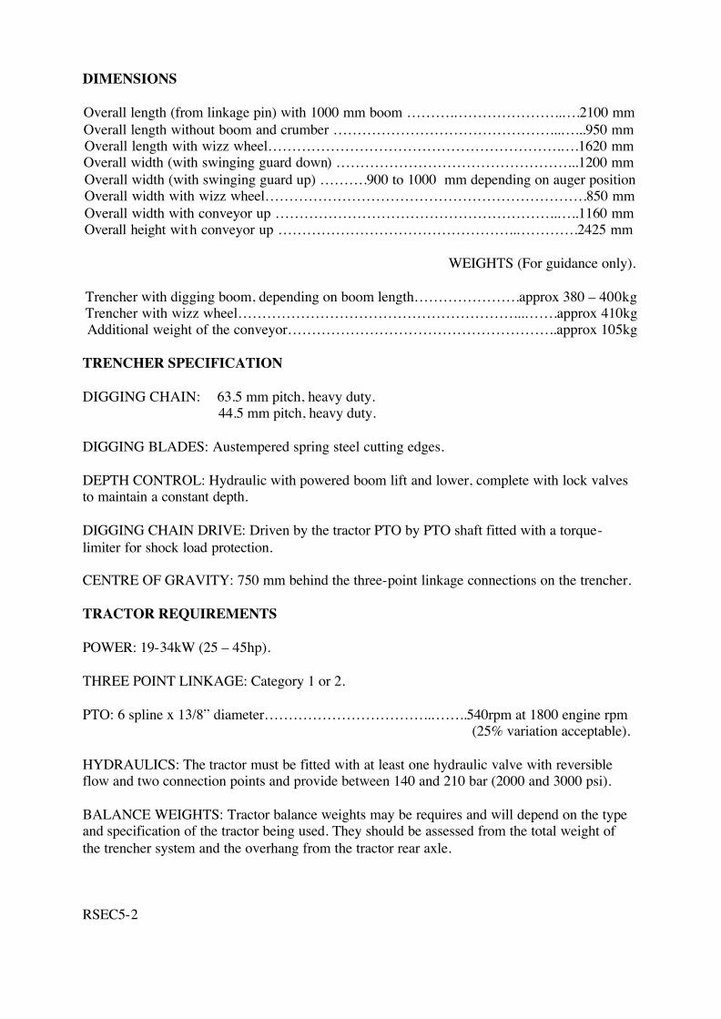
DIMENSIONS Overall length (from linkage pin) with 1000 mm boom ……….…………………..….2100 mm Overall length without boom and crumber ………………………………………...…...950 mm Overall length with wizz wheel…………………………………………………….….1620 mm Overall width (with swinging guard down) …………………………………………...1200 mm Overall width (with swinging guard up) ……….900 to 1000 mm depending on auger position Overall width with wizz wheel………………………………………………………….850 mm Overall width with conveyor up …………………………………………………..…..1160 mm Overall height with conveyor up …………………………………………..………….2425 mm
WEIGHTS (For guidance only).
Trencher with digging boom, depending on boom length………………….approx 380 – 400kg Trencher with wizz wheel…………………………………………………...…….approx 410kg Additional weight of the conveyor………………………………………………..approx 105kg
TRENCHER SPECIFICATION DIGGING CHAIN: 63.5 mm pitch, heavy duty. 44.5 mm pitch, heavy duty. DIGGING BLADES: Austempered spring steel cutting edges. DEPTH CONTROL: Hydraulic with powered boom lift and lower, complete with lock valves to maintain a constant depth. DIGGING CHAIN DRIVE: Driven by the tractor PTO by PTO shaft fitted with a torque-limiter for shock load protection. CENTRE OF GRAVITY: 750 mm behind the three-point linkage connections on the trencher. TRACTOR REQUIREMENTS POWER: 19-34kW (25 – 45hp). THREE POINT LINKAGE: Category 1 or 2. PTO: 6 spline x 13/8” diameter……………………………..……..540rpm at 1800 engine rpm
(25% variation acceptable). HYDRAULICS: The tractor must be fitted with at least one hydraulic valve with reversible flow and two connection points and provide between 140 and 210 bar (2000 and 3000 psi). BALANCE WEIGHTS: Tractor balance weights may be requires and will depend on the type and specification of the tractor being used. They should be assessed from the total weight of the trencher system and the overhang from the tractor rear axle. RSEC5-2
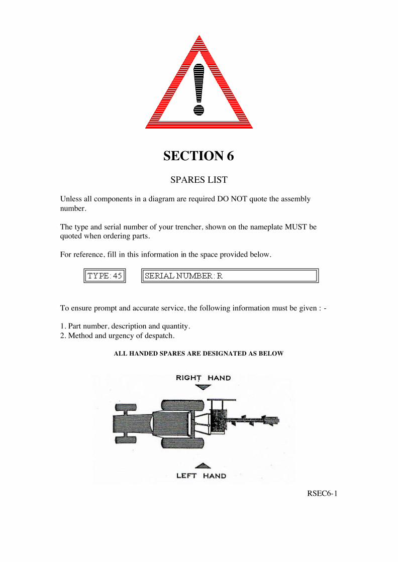
SECTION 6
SPARES LIST
Unless all components in a diagram are required DO NOT quote the assembly number. The type and serial number of your trencher, shown on the nameplate MUST be quoted when ordering parts. For reference, fill in this information in the space provided below.
To ensure prompt and accurate service, the following information must be given : - 1. Part number, description and quantity. 2. Method and urgency of despatch.
ALL HANDED SPARES ARE DESIGNATED AS BELOW
RSEC6-1
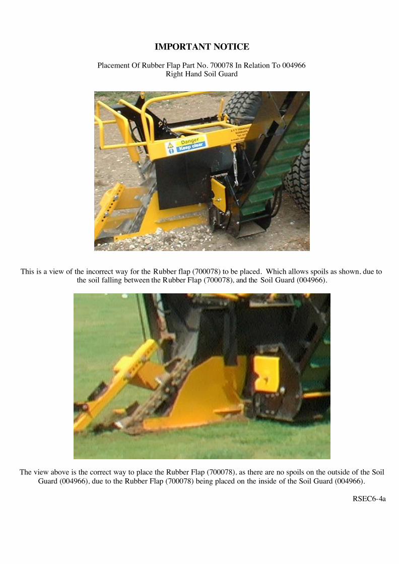
IMPORTANT NOTICE
Placement Of Rubber Flap Part No. 700078 In Relation To 004966 Right Hand Soil Guard
This is a view of the incorrect way for the Rubber flap (700078) to be placed. Which allows spoils as shown, due to
the soil falling between the Rubber Flap (700078), and the Soil Guard (004966).
The view above is the correct way to place the Rubber Flap (700078), as there are no spoils on the outside of the Soil Guard (004966), due to the Rubber Flap (700078) being placed on the inside of the Soil Guard (004966).
RSEC6-4a
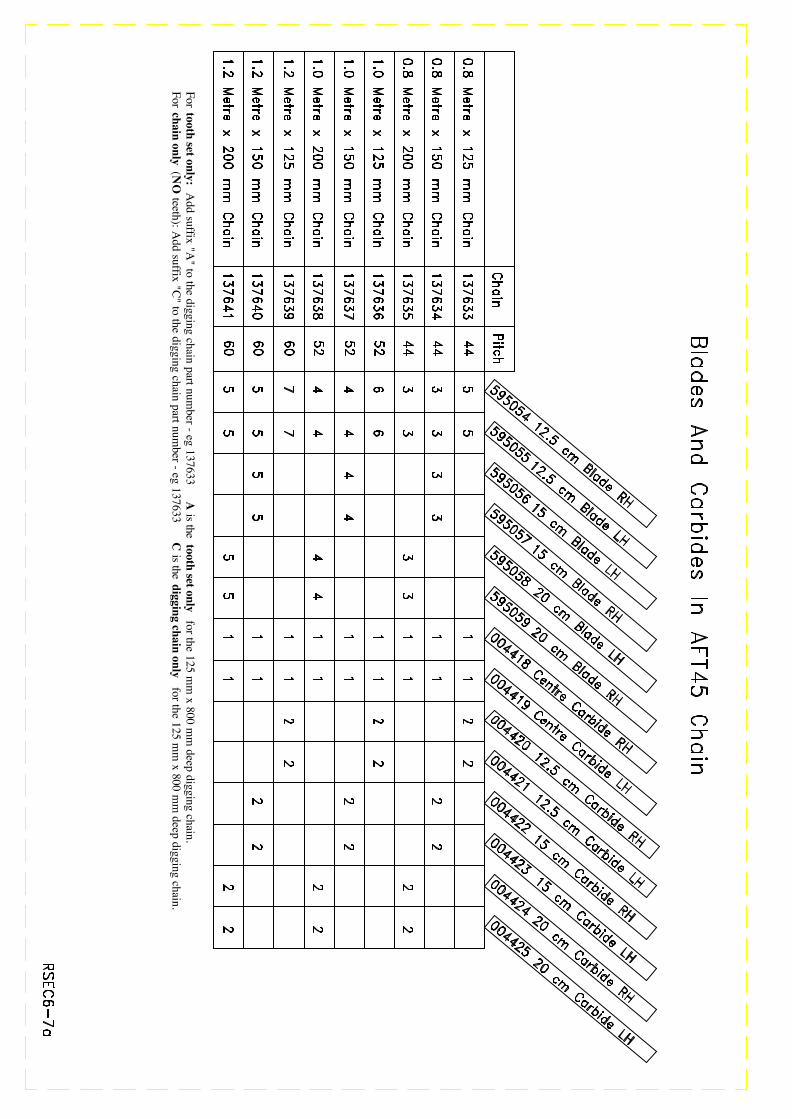
For tooth set only: Add suffix "A
" to the digging chain part number - eg 137633
A is the tooth set only
for the 125 mm
x 800 mm
deep digging chain.For chain only
(NO
teeth): Add suffix "C" to the digging chain part num
ber - eg 137633C
is the digging chain only for the 125 m
m x 800 m
m deep digging chain.
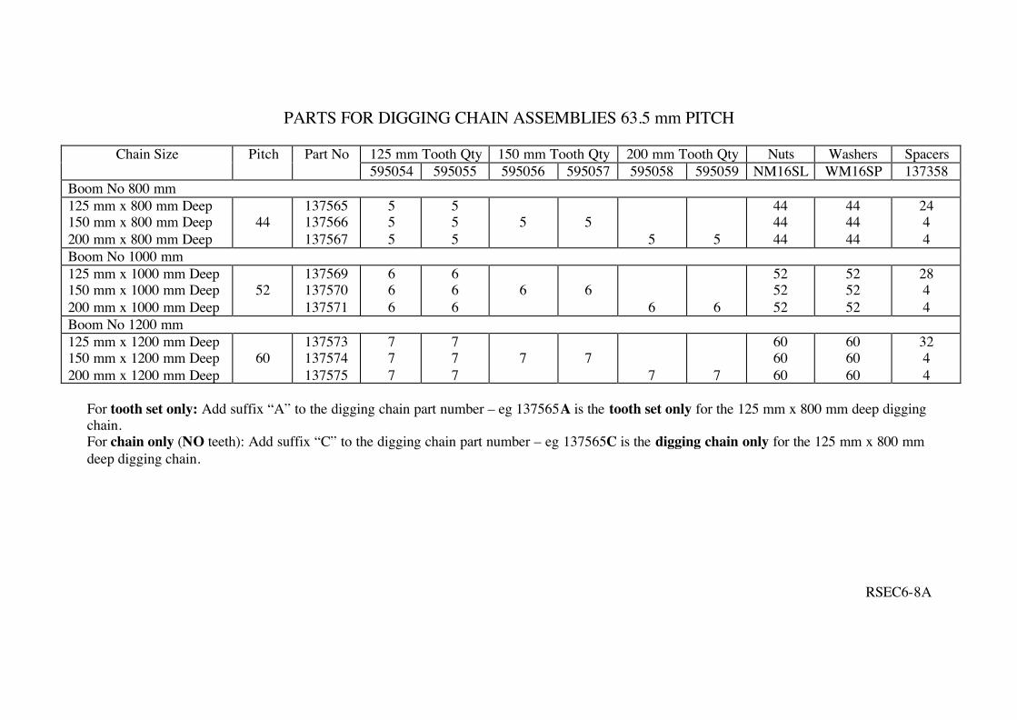
PARTS FOR DIGGING CHAIN ASSEMBLIES 63.5 mm PITCH
125 mm Tooth Qty 150 mm Tooth Qty 200 mm Tooth Qty Nuts Washers Spacers Chain Size Pitch Part No 595054 595055 595056 595057 595058 595059 NM16SL WM16SP 137358
Boom No 800 mm 125 mm x 800 mm Deep 150 mm x 800 mm Deep 200 mm x 800 mm Deep
44
137565 137566 137567
5 5 5
5 5 5
5
5
5
5
44 44 44
44 44 44
24 4 4
Boom No 1000 mm 125 mm x 1000 mm Deep 150 mm x 1000 mm Deep 200 mm x 1000 mm Deep
52
137569 137570 137571
6 6 6
6 6 6
6
6
6
6
52 52 52
52 52 52
28 4 4
Boom No 1200 mm 125 mm x 1200 mm Deep 150 mm x 1200 mm Deep 200 mm x 1200 mm Deep
60
137573 137574 137575
7 7 7
7 7 7
7
7
7
7
60 60 60
60 60 60
32 4 4
For tooth set only: Add suffix “A” to the digging chain part number – eg 137565A is the tooth set only for the 125 mm x 800 mm deep digging chain. For chain only (NO teeth): Add suffix “C” to the digging chain part number – eg 137565C is the digging chain only for the 125 mm x 800 mm deep digging chain.
RSEC6-8A
EC DECLARATION OF CONFORMITY
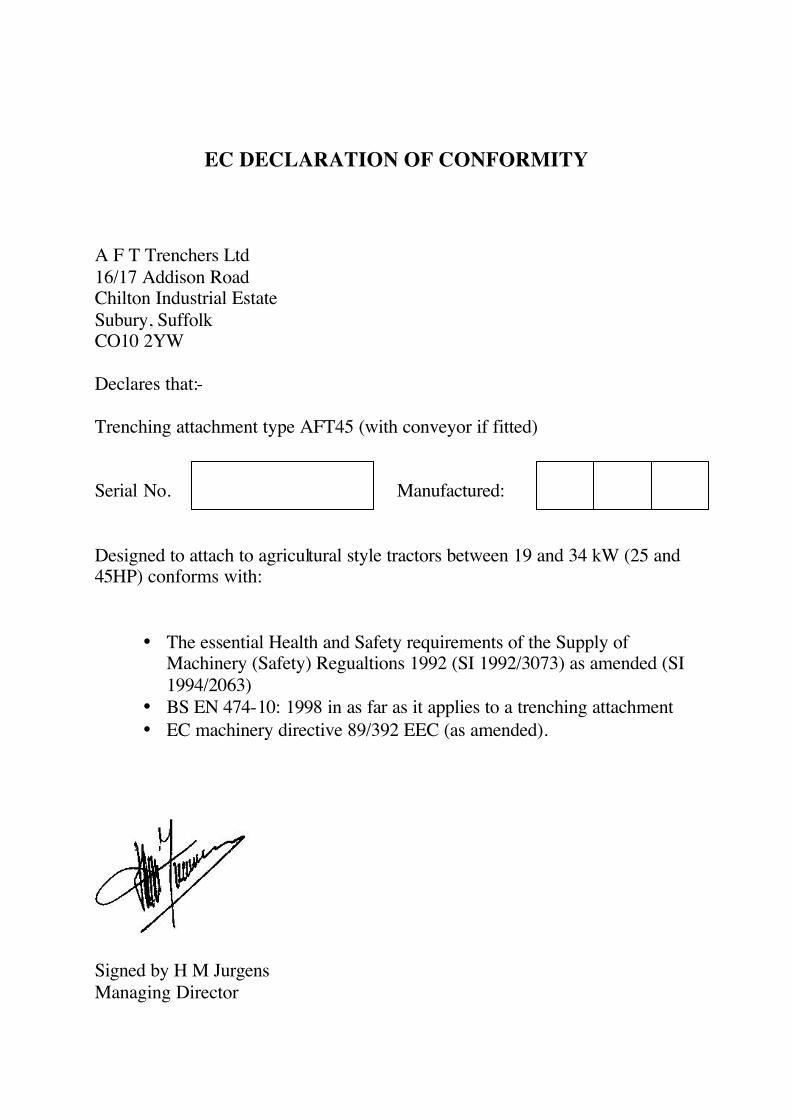
A F T Trenchers Ltd 16/17 Addison Road Chilton Industrial Estate Subury, Suffolk CO10 2YW Declares that:- Trenching attachment type AFT45 (with conveyor if fitted) Serial No. Manufactured: Designed to attach to agricultural style tractors between 19 and 34 kW (25 and 45HP) conforms with:
• The essential Health and Safety requirements of the Supply of Machinery (Safety) Regualtions 1992 (SI 1992/3073) as amended (SI 1994/2063)
• BS EN 474-10: 1998 in as far as it applies to a trenching attachment • EC machinery directive 89/392 EEC (as amended).
Signed by H M Jurgens Managing Director