4 customer connection district heating training … customer connection district heating training...
TRANSCRIPT

4 Customer Connection
District Heating Training Course
B09HV_en
16.04.2002
Mikkeli Polytechnic Siemens Building Technologies
Building Automation
P 2
P 1T I
T IP I
T IP I
T IP I
T IAT E 1
T E2 A T I
T I
T IT I
M V
1
M V
2
T C 1
K IST C 2
T E2 B
L im it o f th e p re -fab rica te d sub statio n
P IA
1 . H D
2 . H D
3 C W
4 H W
5 H W C
H F 6
H R 7H E 1 H E 2
He
ati
ng
uti
lity
Cu
sto
me
r

2/19
Siemens Building Technologies District Heating Training Course B09HV_en
Building Automation 16.04.2002
Siemens Building Technologies Ltd.
Building Automation
Gubelstrasse 22
CH-6301 Zug
Tel. +41 41-724 24 24
Fax +41 41-724 35 22
www.landisstaefa.com
Mikkeli Polytechnic © 2001 Siemens Building Technologies Ltd.
Subject to change

3/19
Siemens Building Technologies District Heating Training Course B09HV_en
Building Automation Table of contents 16.04.2002
Table of contents
4.1 Substation ..................................................................................................... 5
4.1.1 Prefabricated substation ............................................................................... 5
4.2 Connection schemes .................................................................................... 6
4.3 Substation equipment ................................................................................... 7
4.3.1 Heat exchangers ........................................................................................... 7
4.3.2 Pumps ........................................................................................................... 9
4.3.3 Control system ............................................................................................ 10
4.3.4 Other equipment ......................................................................................... 10
4.4 Space heating ............................................................................................. 12
4.4.1 Radiator network ......................................................................................... 12
4.4.2 Floor heating ............................................................................................... 15
4.5 Other systems ............................................................................................. 16
4.5.1 Connection schemes .................................................................................. 16
4.5.1.1 Direct or indirect .......................................................................................... 16
4.5.1.2 Open or closed............................................................................................ 16
4.5.1.3 4 pipe system .............................................................................................. 17
4.5.1.4 Substations for group of buildings............................................................... 17
4.5.2 Trends ......................................................................................................... 17

4/19
Siemens Building Technologies District Heating Training Course B09HV_en
Building Automation Customer connection 16.04.2002
4 Customer connection
Training is familiarised trainee with the customer connection of DH. The trainee will be
able to:
- understand different connections of substations
- name the main components of modern substation
- understand the benefits of prefabricated substation
- name the different types of heat exchangers and other equipment
- explain the design and control strategies of SH systems for DH
The customer connection consists of the metering centre and substation. The metering
and metering centre is discussed more in chapter 8.
The target in DH-system is to make and to distribute heat energy over a large area as
economically as possible. System must be economical both to the customer and the
heating company (Heat Vendor). This means that high quality equipment are needed
though the whole field of DH-system.
The control of heat production plants shortly means the regulation of DH supply water
temperature and the pressure levels in DH network. The economy and the control
strategy of DH network depend also on the types of connections of the customer. In the
history of DH technology there has been a lot of different kinds of “connections”. Some
of these are presented in chapter 4.5.
After a long experience in Scandinavia the best strategy to control the economy of DH
network is to use the customer owned substations with heat exchangers. In this kind of
controlling concept customer is connected individually and customers heating networks
and DH distribution network are completely separated hydraulically by heat
exchangers. Connection of the customer oriented control and automation system
enable independent energy consumption for the each customer. Using the substation is
also important because the pressure and the temperature conditions are varied a lot in
DH distribution network. Other important point is to protect buildings for water damages
if secondary network is leaking.
Fig 4- 1 Prefabricated substation
Learning goals
Why a substation
5/19
Siemens Building Technologies District Heating Training Course B09HV_en
Building Automation Customer connection 16.04.2002
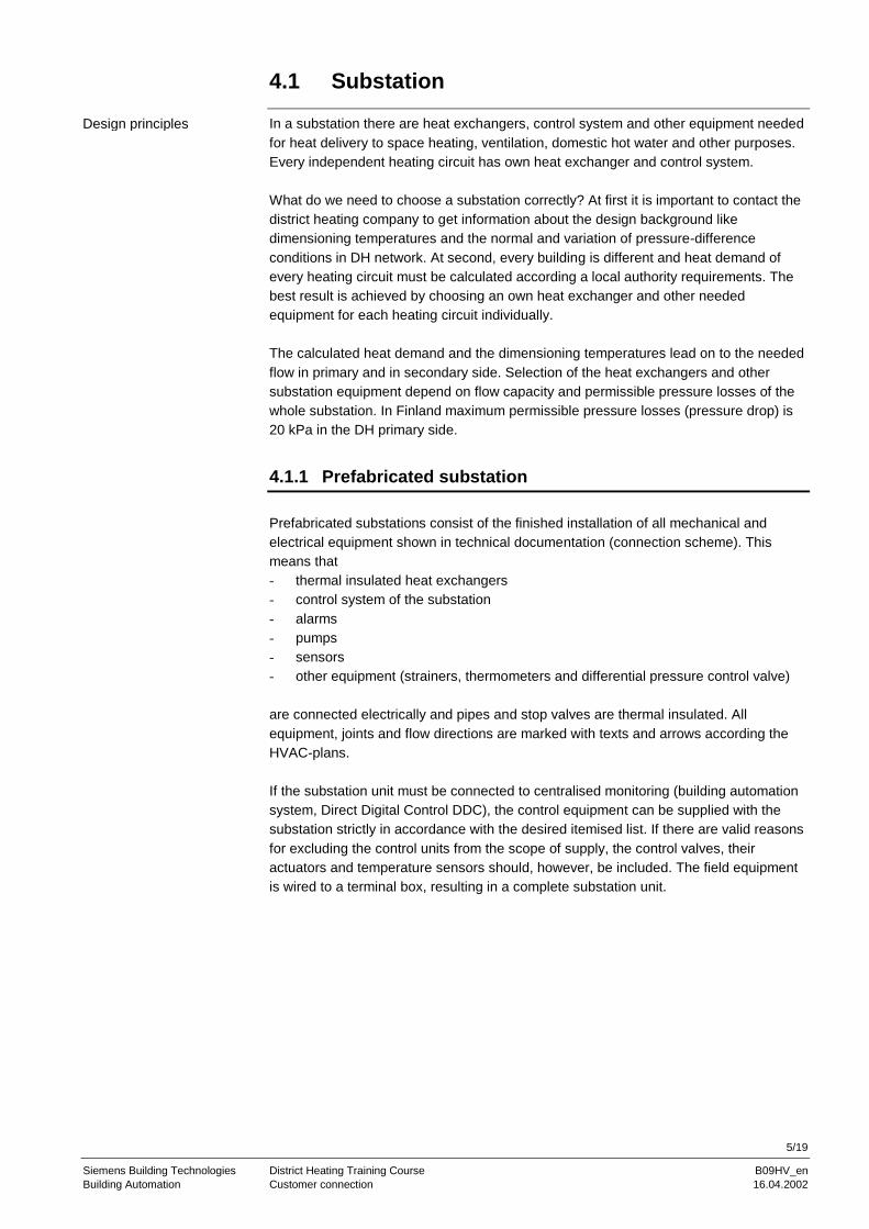
4.1 Substation
In a substation there are heat exchangers, control system and other equipment needed
for heat delivery to space heating, ventilation, domestic hot water and other purposes.
Every independent heating circuit has own heat exchanger and control system.
What do we need to choose a substation correctly? At first it is important to contact the
district heating company to get information about the design background like
dimensioning temperatures and the normal and variation of pressure-difference
conditions in DH network. At second, every building is different and heat demand of
every heating circuit must be calculated according a local authority requirements. The
best result is achieved by choosing an own heat exchanger and other needed
equipment for each heating circuit individually.
The calculated heat demand and the dimensioning temperatures lead on to the needed
flow in primary and in secondary side. Selection of the heat exchangers and other
substation equipment depend on flow capacity and permissible pressure losses of the
whole substation. In Finland maximum permissible pressure losses (pressure drop) is
20 kPa in the DH primary side.
4.1.1 Prefabricated substation
Prefabricated substations consist of the finished installation of all mechanical and
electrical equipment shown in technical documentation (connection scheme). This
means that
- thermal insulated heat exchangers
- control system of the substation
- alarms
- pumps
- sensors
- other equipment (strainers, thermometers and differential pressure control valve)
are connected electrically and pipes and stop valves are thermal insulated. All
equipment, joints and flow directions are marked with texts and arrows according the
HVAC-plans.
If the substation unit must be connected to centralised monitoring (building automation
system, Direct Digital Control DDC), the control equipment can be supplied with the
substation strictly in accordance with the desired itemised list. If there are valid reasons
for excluding the control units from the scope of supply, the control valves, their
actuators and temperature sensors should, however, be included. The field equipment
is wired to a terminal box, resulting in a complete substation unit.
Design principles
6/19
Siemens Building Technologies District Heating Training Course B09HV_en
Building Automation Customer connection 16.04.2002
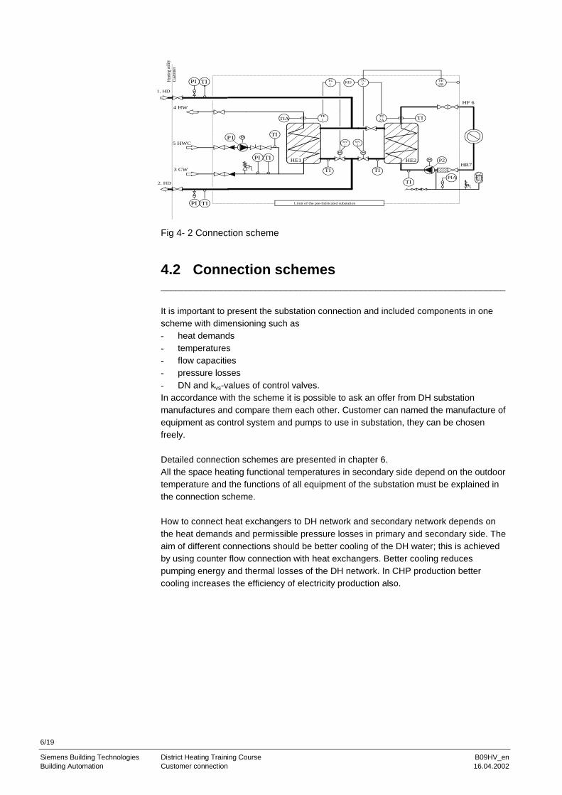
Fig 4- 2 Connection scheme
4.2 Connection schemes _____________________________________________________________________
It is important to present the substation connection and included components in one
scheme with dimensioning such as
- heat demands
- temperatures
- flow capacities
- pressure losses
- DN and kvs-values of control valves.
In accordance with the scheme it is possible to ask an offer from DH substation
manufactures and compare them each other. Customer can named the manufacture of
equipment as control system and pumps to use in substation, they can be chosen
freely.
Detailed connection schemes are presented in chapter 6.
All the space heating functional temperatures in secondary side depend on the outdoor
temperature and the functions of all equipment of the substation must be explained in
the connection scheme.
How to connect heat exchangers to DH network and secondary network depends on
the heat demands and permissible pressure losses in primary and secondary side. The
aim of different connections should be better cooling of the DH water; this is achieved
by using counter flow connection with heat exchangers. Better cooling reduces
pumping energy and thermal losses of the DH network. In CHP production better
cooling increases the efficiency of electricity production also.
P2
P1TI
TIPI
TIPI
TIPI
TIATE 1
TE2A TI
TI
TITI
MV
1
MV
2
TC 1
KISTC 2
TE2B
Limit of the pre-fabricated substation
PIA
1. HD
2. HD
3 CW
4 HW
5 HWC
HF 6
HR7HE1 HE2
Hea
ting
utili
ty
Cus
tom
er
7/19
Siemens Building Technologies District Heating Training Course B09HV_en
Building Automation Customer connection 16.04.2002
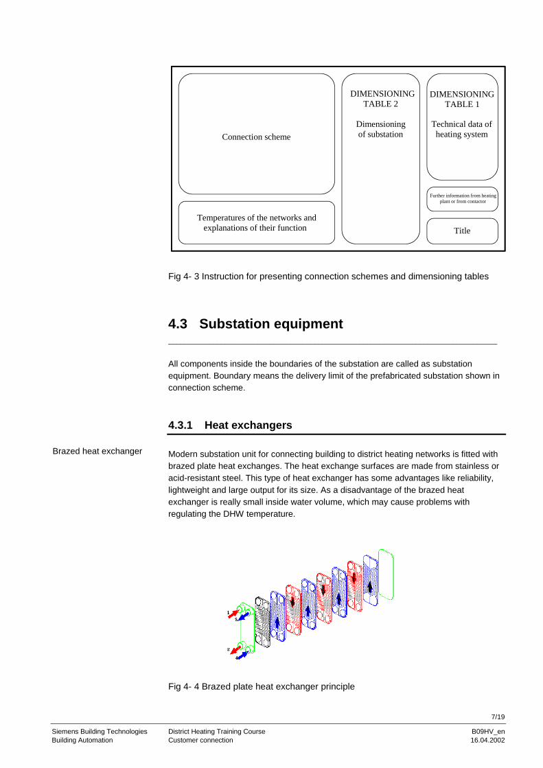
Fig 4- 3 Instruction for presenting connection schemes and dimensioning tables
4.3 Substation equipment _________________________________________________________________________________
All components inside the boundaries of the substation are called as substation
equipment. Boundary means the delivery limit of the prefabricated substation shown in
connection scheme.
4.3.1 Heat exchangers
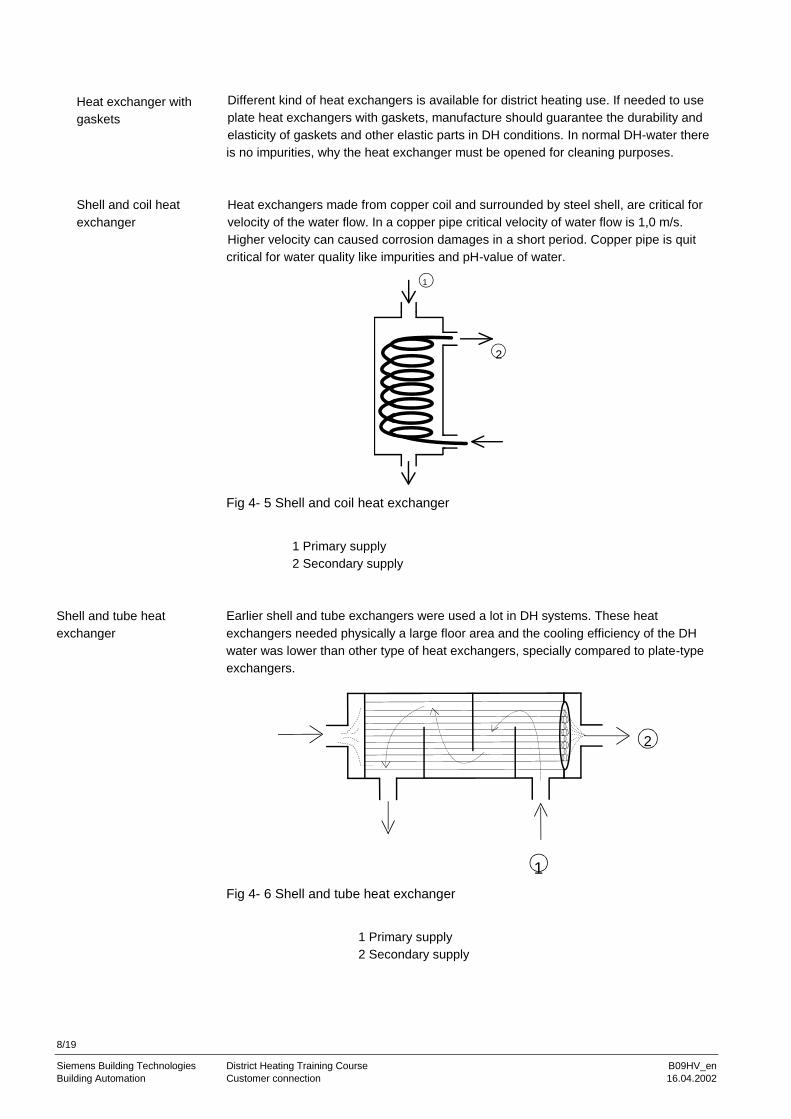
Modern substation unit for connecting building to district heating networks is fitted with
brazed plate heat exchanges. The heat exchange surfaces are made from stainless or
acid-resistant steel. This type of heat exchanger has some advantages like reliability,
lightweight and large output for its size. As a disadvantage of the brazed heat
exchanger is really small inside water volume, which may cause problems with
regulating the DHW temperature.
Fig 4- 4 Brazed plate heat exchanger principle
Brazed heat exchanger
Connection scheme
Temperatures of the networks and
explanations of their function
DIMENSIONING
TABLE 2
Dimensioning
of substation
DIMENSIONING
TABLE 1
Technical data of
heating system
Further information from heating
plant or from contactor
Title
8/19
Siemens Building Technologies District Heating Training Course B09HV_en
Building Automation Customer connection 16.04.2002
Different kind of heat exchangers is available for district heating use. If needed to use
plate heat exchangers with gaskets, manufacture should guarantee the durability and
elasticity of gaskets and other elastic parts in DH conditions. In normal DH-water there
is no impurities, why the heat exchanger must be opened for cleaning purposes.
Heat exchangers made from copper coil and surrounded by steel shell, are critical for
velocity of the water flow. In a copper pipe critical velocity of water flow is 1,0 m/s.
Higher velocity can caused corrosion damages in a short period. Copper pipe is quit
critical for water quality like impurities and pH-value of water.
Fig 4- 5 Shell and coil heat exchanger
1 Primary supply
2 Secondary supply
Earlier shell and tube exchangers were used a lot in DH systems. These heat
exchangers needed physically a large floor area and the cooling efficiency of the DH
water was lower than other type of heat exchangers, specially compared to plate-type
exchangers.
Fig 4- 6 Shell and tube heat exchanger
1 Primary supply
2 Secondary supply
Heat exchanger with
gaskets
Shell and coil heat
exchanger
Shell and tube heat
exchanger
2
1
1
2

9/19
Siemens Building Technologies District Heating Training Course B09HV_en
Building Automation Customer connection 16.04.2002
Regardless of the type and the material of the heat exchanger, the basic idea is that
heat exchangers shall be dimensioned and build so that cooling of the DH water is as
effective as possible in all conditions and all water flow run along the heat exchange
surfaces. If the temperature difference in the secondary network is small (e.g. in floor
heating systems), a part of the secondary flow can pass the heat exchanger. It is
forbidden to mix the secondary supply water with the secondary return water. Heat
exchangers must have thermal insulation and all joints must be clearly marked.
4.3.2 Pumps
Pumps are needed to circulate the secondary water for heating and for domestic hot
water re circulation use. Only centrifugal pumps are used in DH substations. For
dimensioning the pump capacity (flow) and pressure loss in piping and in heat
exchanger (head) are needed. It is recommended to use pumps, which rotational speed
is not over 1500 r/min. Higher rotation speed may caused problems with the
permissible noise level in buildings.
Selection of pumps must be able to fulfil the maximum required flow and pressure
(pump head). To ensure optimum operation economy, the pump should be selected so,
that duty point location is on the highest part of the efficiency curve.
Pump markings like
- manufacture
- type
- capacity
- head
- electrical power demand
must be clearly and durability marked on the pump. In some cases it is recommended
to have a stand-by pump for maintenance meaning for critical secondary network.
Fig 4- 7 Pump head / volume flow
1 characteristic curve of pump
2 piping system pressure curve
Selection
kPa
dm / s3
12
10/19
Siemens Building Technologies District Heating Training Course B09HV_en
Building Automation Customer connection 16.04.2002
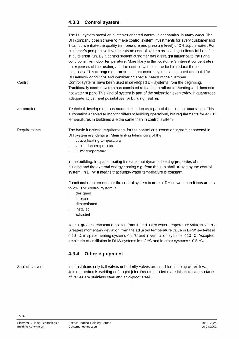
4.3.3 Control system
The DH system based on customer oriented control is economical in many ways. The
DH company doesn’t have to make control system investments for every customer and
it can concentrate the quality (temperature and pressure level) of DH supply water. For
customer’s perspective investments on control system are leading to financial benefits
in quite short run. By a control system customer has a straight influence to the living
conditions like indoor temperature. More likely is that customer’s interest concentrates
on expenses of the heating and the control system is the tool to reduce these
expenses. This arrangement presumes that control systems is planned and build for
DH network conditions and considering special needs of the customer.
Control systems have been used in developed DH systems from the beginning.
Traditionally control system has consisted at least controllers for heating and domestic
hot water supply. This kind of system is part of the substation even today. It guarantees
adequate adjustment possibilities for building heating.
Technical development has made substation as a part of the building automation. This
automation enabled to monitor different building operations, but requirements for adjust
temperatures in buildings are the same than in control system.
The basic functional requirements for the control or automation system connected in
DH system are identical. Main task is taking care of the
- space heating temperature
- ventilation temperature
- DHW temperature
in the building. In space heating it means that dynamic heating properties of the
building and the external energy coming e.g. from the sun shall utilised by the control
system. In DHW it means that supply water temperature is constant.
Functional requirements for the control system in normal DH network conditions are as
follow. The control system is
- designed
- chosen
- dimensioned
- installed
- adjusted
so that greatest constant deviation from the adjusted water temperature value is 2 C.
Greatest momentary deviation from the adjusted temperature value in DHW systems is
10 C, in space heating systems 5 C and in ventilation systems 10 C. Accepted
amplitude of oscillation in DHW systems is 2 C and in other systems 0,5 C.
4.3.4 Other equipment
In substations only ball valves or butterfly valves are used for stopping water flow.
Joining method is welding or flanged joint. Recommended materials in closing surfaces
of valves are stainless steel and acid-proof steel.
Control
Automation
Requirements
Shut-off valves

11/19
Siemens Building Technologies District Heating Training Course B09HV_en
Building Automation Customer connection 16.04.2002
Fig 4- 8 Steel ball valve
Substation must be equipped with safety valve for water expansion and in case of
breakdown of the control system. The best place to install secondary side expansion
pipe is in the suction side of the pump connected to the return pipe.
Pipes used in substation must sustain in DH temperature and pressure conditions
unchanged. The most common materials used in piping are steel and copper. Joining
methods are welding or brazing.
It is recommended to use strainers with plate-type heat exchangers both, in primary
and in secondary side, assure uninterrupted usage of the substation.
Thermometer and other sensor pockets are made of stainless steel, acid-proof steel of
copper.
All materials used in substation manufacturing will be chosen so that they sustain in
normal DH network conditions the whole living time of the substation. It is forbidden to
use cast iron as a primary side material.
If the pressure difference of the DH network fluctuates more than 400 kPa (4 bar),
recommended to use the pressure difference valve (regulation).
High pressure difference caused problems for the regulation result and may caused
cavitation in control valves.
Combination valve is a control valve with pressure difference control function.
Fig 4- 9 Combination valve
More detailed information is in chapter 7.
Safety valve
Pipes
Strainers
Sensor pockets
Materials
Pressure control

12/19
Siemens Building Technologies District Heating Training Course B09HV_en
Building Automation Customer connection 16.04.2002
4.4 Space heating __________________________________________________________________________________
SH systems of the building connected to DH system should be designed and installed
so, that
energy consumption (kWh) and heating capacity (kW) is as low as possible
control system can utilise internal heat sources (sun, lights, occupants,
machines etc.)
heat capacity of the structures can be utilised for saving energy and thermal
power
temperatures of SH networks are adjustable according the outside temperature
and at the lowest possible level
control system can operate in variable DH pressure conditions
SH networks need as little hydraulic balancing as possible.
All the circuits of SH networks should be set in hydraulic balance. This is done by using
balancing valves both for each network line and for each radiator. By these balancing
valves you set beforehand the needed water flow for each line and radiator.
The expansion system of SH networks should be so called closed system. In an open
system there is always great possibility to get air (O2) to your system and the danger for
corrosion in your network is obvious. In normal buildings the membrane expansion
vessels are used. In high rise buildings you can use compressor system or pump
controlled system. The expansion vessels should be dimensioned according to physical
properties of heating fluid. For the normal heating water the expansion is approximately
2,5 … 3,5 % of the total water volume of network. Note that the water temperature also
in secondary side of DH could rise up to 110 … 115 oC if for instance the control valve
is jammed in open position.
The safety valves should be dimensioned according to local pressure regulations and
standards.
4.4.1 Radiator network
In DH connected radiator network it is possible to use all normal network structures.
General aims
Hydraulic balancing
Expansion and safety
Systems
1
2
3
13/19
Siemens Building Technologies District Heating Training Course B09HV_en
Building Automation Customer connection 16.04.2002
Fig 4-8 Structures on radiator networks
1 Normal 2-pipe system
2 2-pipe system with reverse return (Tichelman’s system)
3 1-pipe system
In normal 2-pipe system (Fig 4-8) the radiators are connected parallel to pipelines. In
this system the advantage is easy dimensioning of radiators because each radiator has
the same dimensioning temperature (logarithmic mean temperature between the
radiator surface and indoor air temperature). The greatest disadvantage is the natural
hydraulic unbalance of this system. Each radiator has different pressure losses so the
normal 2-pipe system needs quit a lot work in hydraulic balancing.
In 2-pipe system with reverse return (Tichelman’s system; Fig 4-8) this disadvantage is
avoided. Now each radiator has about the same pressure losses so the hydraulic
balancing is quite easy.
In 1-pipe system (Fig 4-8) the radiators are connected series to pipelines. In this
system the disadvantage is laborious dimensioning of radiator because each radiator
has different dimensioning temperature (logarithmic mean temperature between the
radiator surface and indoor air temperature).
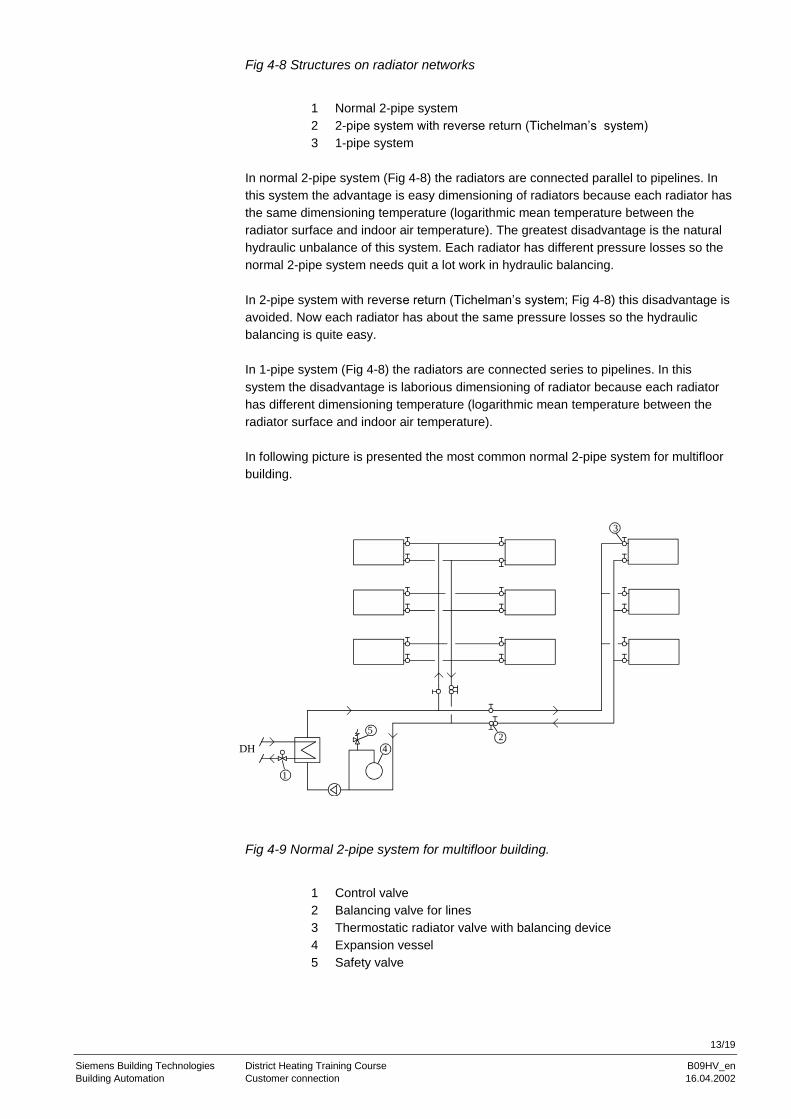
In following picture is presented the most common normal 2-pipe system for multifloor
building.
Fig 4-9 Normal 2-pipe system for multifloor building.
1 Control valve
2 Balancing valve for lines
3 Thermostatic radiator valve with balancing device
4 Expansion vessel
5 Safety valve
5
4
1
2
3
DH
14/19
Siemens Building Technologies District Heating Training Course B09HV_en
Building Automation Customer connection 16.04.2002
The normal design temperatures for new DH connected radiator network are
supply: ts = 70 oC (=maximum temperature in new buildings)
return: tr = 40 oC (=maximum temperature in new buildings)
The return temperature of DH connected SH network can be lower than in most non-
condensing boiler heated networks because there is no risk for corrosion. Of course
this is up to the fuel you use.
Note the influence of temperature difference T = ts - tr for the characteristic of radiator
and further for thermostatic radiator valve characteristic (Fig 4-10).
The design temperatures of radiator network shall be discussed more detailed in
chapter 6.
According to above named general aims the best control strategy of radiator networks
is to regulate the supply water temperature according to outdoor temperature. Because
this is centralised control for whole network you need an extra system to control the
indoor air temperature in each room.
Control system for radiator network shall be discussed more detailed in chapter 6.
Normally you use thermostatic radiator valves for controlling indoor temperatures in
each room of the building. Another important task for the thermostatic radiator valve is
to utilise the internal heat sources and save the heating energy.
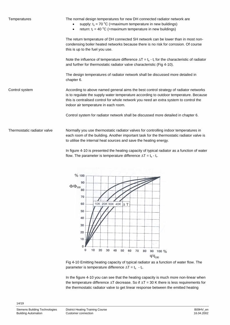
In figure 4-10 is presented the heating capacity of typical radiator as a function of water
flow. The parameter is temperature difference T = ts - tr.
Fig 4-10 Emitting heating capacity of typical radiator as a function of water flow. The
parameter is temperature difference T = ts - tr.
In the figure 4-10 you can see that the heating capacity is much more non-linear when
the temperature difference T decrease. So if T = 30 K there is less requirements for
the thermostatic radiator valve to get linear response between the emitted heating
Temperatures
Control system
Thermostatic radiator valve
%
%q/q
100
100
T
15/19
Siemens Building Technologies District Heating Training Course B09HV_en
Building Automation Customer connection 16.04.2002
capacity and flow. If T = 10 K the curve is quite non-liner upwards so you need the
valve which have characteristic strongly downwards to get the linear response.
Note also that the radiators might be difficult to control at small loads because the
heating capacity is very dependant on the flow. In real rooms the thermostatic radiator
valves work most of the time at quite small loads.
4.4.2 Floor heating
Due to the local thermal discomfort caused by the surface temperatures of floor the
water temperatures of floor heating are restricted. In Table 4-1 is presented the surface
temperatures of floor according to EU thermal comfort recommendations.
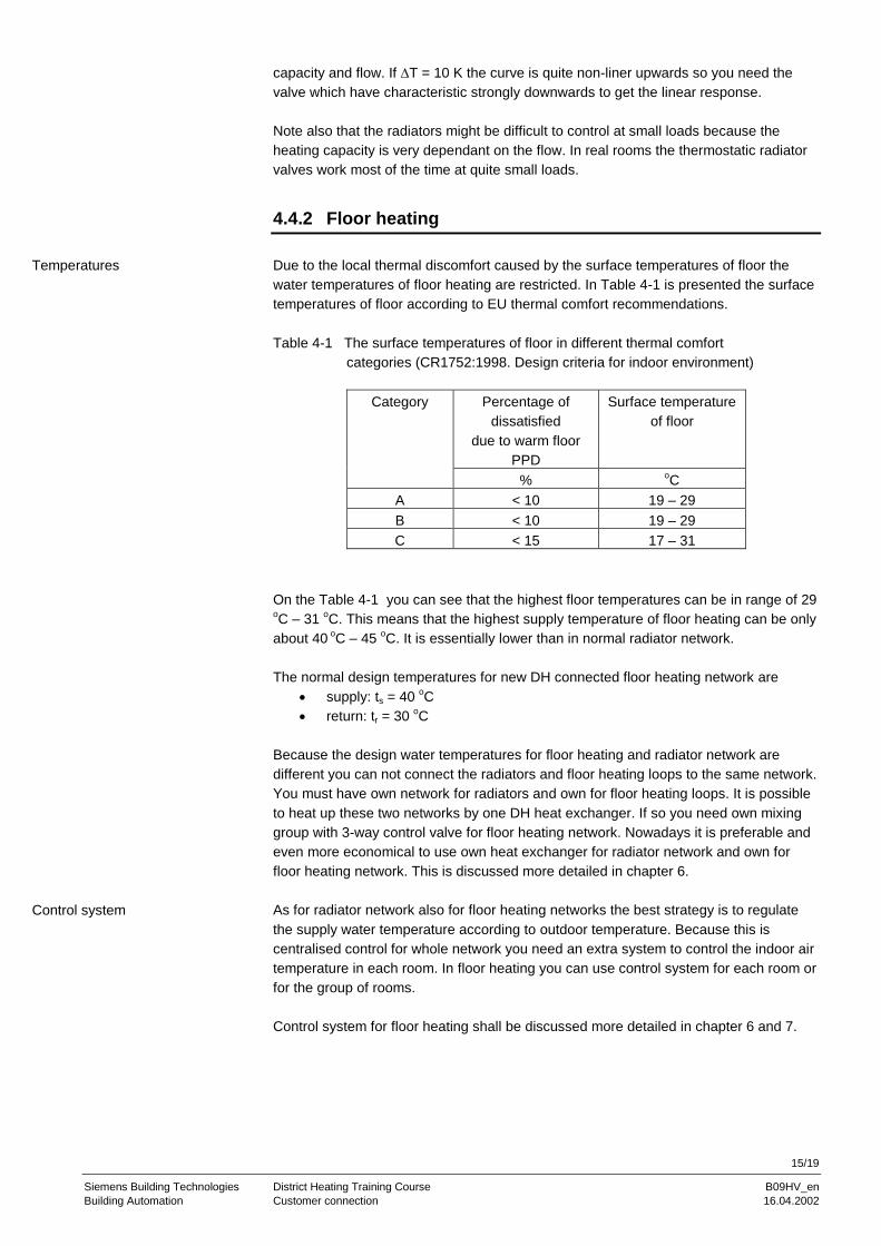
Table 4-1 The surface temperatures of floor in different thermal comfort
categories (CR1752:1998. Design criteria for indoor environment)
Category Percentage of
dissatisfied
due to warm floor
PPD
Surface temperature
of floor
% oC
A < 10 19 – 29
B < 10 19 – 29
C < 15 17 – 31
On the Table 4-1 you can see that the highest floor temperatures can be in range of 29 oC – 31
oC. This means that the highest supply temperature of floor heating can be only
about 40 oC – 45
oC. It is essentially lower than in normal radiator network.
The normal design temperatures for new DH connected floor heating network are
supply: ts = 40 oC
return: tr = 30 oC
Because the design water temperatures for floor heating and radiator network are
different you can not connect the radiators and floor heating loops to the same network.
You must have own network for radiators and own for floor heating loops. It is possible
to heat up these two networks by one DH heat exchanger. If so you need own mixing
group with 3-way control valve for floor heating network. Nowadays it is preferable and
even more economical to use own heat exchanger for radiator network and own for
floor heating network. This is discussed more detailed in chapter 6.
As for radiator network also for floor heating networks the best strategy is to regulate
the supply water temperature according to outdoor temperature. Because this is
centralised control for whole network you need an extra system to control the indoor air
temperature in each room. In floor heating you can use control system for each room or
for the group of rooms.
Control system for floor heating shall be discussed more detailed in chapter 6 and 7.
Temperatures
Control system
16/19
Siemens Building Technologies District Heating Training Course B09HV_en
Building Automation Customer connection 16.04.2002
4.5 Other systems
In this chapter some features of present Central and Eastern Europe systems will be
described. It is essential to understand some basics of those systems to find out
possible renovation solutions and possibilities.
4.5.1 Connection schemes
Heating systems can be either
- Open or closed
- Direct or indirect
The differences between these systems are described in following.
4.5.1.1 Direct or indirect
Indirect
The term ‘indirect’ has been used to describe an indirect space heating system, which
means that the district heating network and the radiator circuit are hydraulically
separated from each other by means of heat exchangers (see also “direct”). In addition,
an equivalent term 'independent' is used.
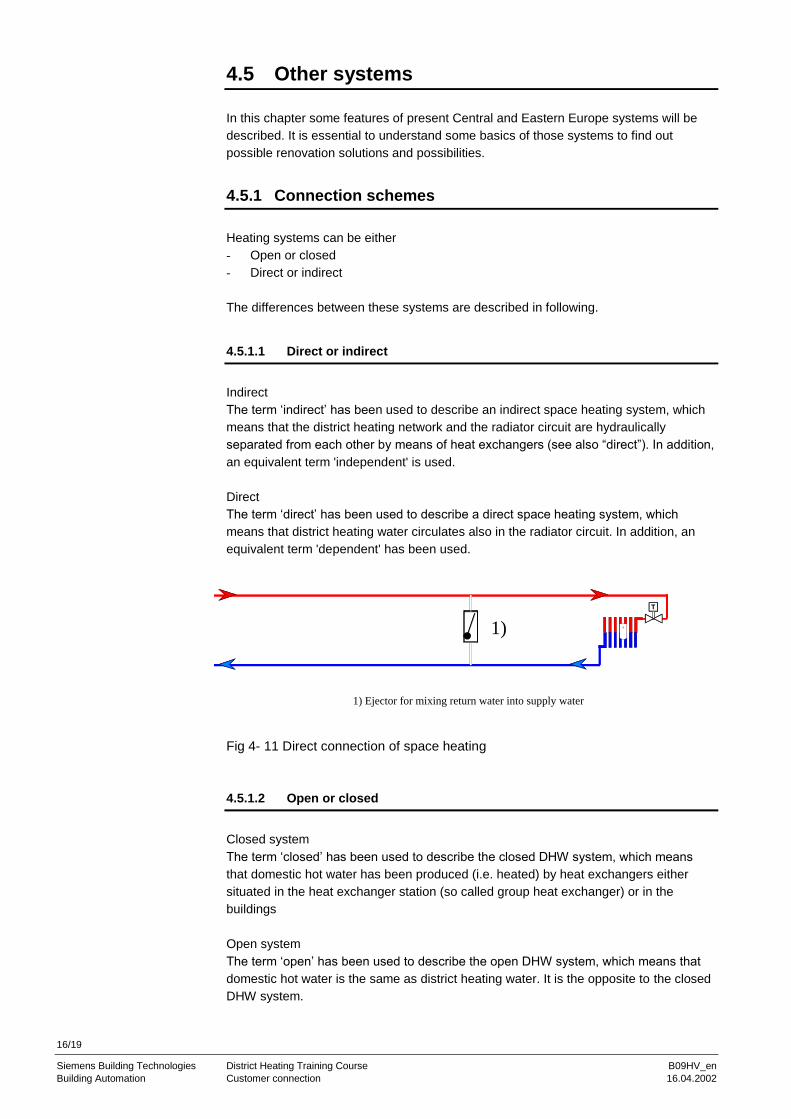
Direct
The term ‘direct’ has been used to describe a direct space heating system, which
means that district heating water circulates also in the radiator circuit. In addition, an
equivalent term 'dependent' has been used.
Fig 4- 11 Direct connection of space heating
4.5.1.2 Open or closed
Closed system
The term ‘closed’ has been used to describe the closed DHW system, which means
that domestic hot water has been produced (i.e. heated) by heat exchangers either
situated in the heat exchanger station (so called group heat exchanger) or in the
buildings
Open system
The term ‘open’ has been used to describe the open DHW system, which means that
domestic hot water is the same as district heating water. It is the opposite to the closed
DHW system.
1)
1) Ejector for mixing return water into supply water

17/19
Siemens Building Technologies District Heating Training Course B09HV_en
Building Automation Customer connection 16.04.2002
Fig 4- 12 Open and direct DH connection
4.5.1.3 4 pipe system
The term ‘4-pipe system’ has usually been used to describe a variation of the closed
DHW system, which means that domestic hot water has been produced (i.e. heated) by
heat exchangers situated in the heat exchanger station (so called group heat
exchanger) and led to the building with one DHW supply pipeline and a re-circulating
return pipeline (the re-circulating pipeline quite usually is missing in Eastern Europe
systems).
4.5.1.4 Substations for group of buildings
Building level substation is normal in Scandinavian DH systems. In Eastern and Central
Europe DHW is quite often produced in large group heat exchangers.
In these kind of open systems the demand of supply water into the system is huge
during the peak DHW consumption period.
Space heating can be produced in heat exchangers or the connection can also be
direct.
4.5.2 Trends
In Eastern and Central Europe more and more DH systems will be changing towards to
Western system presented in this paper. There will be different kinds of problems
dimensioning and planning the systems during this transition period, when both
systems are in operation.
Trend in DH systems are:
- Lower temperature levels in distribution and consumption
- Plastic pipes will come more popular
- Amount of small CHP plants will increase
T1)
T1)
1)
1) Ejector for mixing return water into supply water
2) Space heating
3) DHW
2)

18/19
Siemens Building Technologies District Heating Training Course B09HV_en
Building Automation Index 16.04.2002
Index

19/19
Siemens Building Technologies District Heating Training Course B09HV_en
Building Automation 16.04.2002
Siemens Building Technologies Ltd.
Building Automation
Gubelstrasse 22
CH-6301 Zug
Tel. +41 41-724 24 24
Fax +41 41-724 35 22
www.landisstaefa.com
© 2001 Siemens Building Technologies Ltd.
Subject to change