382 dn 15-20 - sed-flowcontrol.com · temperature range pvc-u: 0 °c - 60 °c - pvc-c: 0 °c - 100...
TRANSCRIPT
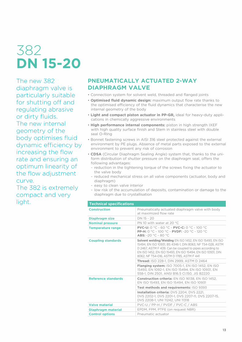
The new 382 diaphragm valve is particularly suitable for shutting off and regulating abrasive or dirty fluids.The new internal geometry of the body optimises fluid dynamic efficiency by increasing the flow rate and ensuring an optimum linearity of the flow adjustment curve. The 382 is extremely compact and very light.
13
382DN 15-20
Technical specifications
Construction Pneumatically actuated diaphragm valve with body at maximized flow rate
Diaphragm size DN 15 - 20
Nominal pressure PN 10 with water at 20 °C
Temperature range PVC-U: 0 °C - 60 °C - PVC-C: 0 °C - 100 °CPP-H: 0 °C - 100 °C - PVDF: -20 °C - 120 °CABS: -20 °C - 80 °C
Coupling standards Solvent welding/Welding EN ISO 1452, EN ISO 15493, EN ISO 15494, EN ISO 10931, BS 4346-1, DIN 8063, NF T54-028, ASTM D 2467, ASTM F 439. Can be coupled to pipes according to EN ISO 1452, EN ISO 15493, EN ISO 15494, EN ISO 10931, DIN 8062, NF T54-016, ASTM D 1785, ASTM F 441
Thread: ISO 228-1, DIN 2999, ASTM D 2464
Flanging system: ISO 7005-1, EN ISO 1452, EN ISO 15493, EN 1092-1, EN ISO 15494, EN ISO 10931, EN 558-1, DIN 2501, ANSI B16.5 Cl.150, JIS B2220
Reference standards Construction criteria: EN ISO 16138, EN ISO 1452, EN ISO 15493, EN ISO 15494, EN ISO 10931
Test methods and requirements: ISO 9393
Installation criteria: DVS 2204, DVS 2221, DVS 2202-1, DVS 2201-1, DVS 2207-11, DVS 2207-15, DVS 2208-1, UNI 11242, UNI 11318
Valve material PVC-U / PP-H / PVDF / PVC-C / ABS
Diaphragm material EPDM, FPM, PTFE (on request NBR)
Control options Pneumatic actuator
PNEUMATICALLY ACTUATED 2-WAY DIAPHRAGM VALVE• Connection system for solvent weld, threaded and flanged joints
• optimised fluid dynamic design: maximum output flow rate thanks to the optimised efficiency of the fluid dynamics that characterise the new internal geometry of the body
• Light and compact piston actuator in PP-GR, ideal for heavy-duty appli-cations in chemically aggressive environments
• High performance internal components: piston in high strength IXEF with high quality surface finish and Stem in stainless steel with double seal O-Ring
• Bonnet fastening screws in AISI 316 steel protected against the external environment by PE plugs. Absence of metal parts exposed to the external environment to prevent any risk of corrosion
• CDSA (Circular Diaphragm Sealing Angle) system that, thanks to the uni-form distribution of shutter pressure on the diaphragm seal, offers the following advantages:- reduction in the tightening torque of the screws fixing the actuator to
the valve body- reduced mechanical stress on all valve components (actuator, body and
diaphragm)- easy to clean valve interior- low risk of the accumulation of deposits, contamination or damage to the
diaphragm due to crystallisation

14
Technical specifications - pneumatic actuator
Construction Single-acting (NC-NO) and double-acting (DA) pneumatic piston actuator
Actuator Material Body and bonnet: PP-GRPosition indicator cap PC
Control air pressure Minimum: according to the working pressure and operation of the actuator (see detailed graphs)
Maximum: NC: 7 bar - NO: 5 bar - DA: 5 bar
Power supply Dry or lubricated filtered compressed air. If using other fluids, contact the SED service centre
Control fluid temperature Max 40 °C
Working temperature -20 °C - 50 °C
Standard equipment • Optical position indicator
Accessories • Stroke limiter with position indicator• Stroke limiter with position indicator and
emergency manual override• Limit switch boxes• Electro-pneumatic positioner• Pilot solenoid valves 3-5/2 ways for direct or
manifold mounting• Distance plate
The new compact and light piston actuator in PP-GR makes the 382 the ideal choice for applications requiring very frequent valve operation and a long valve lifetime.

15
1 High visibility optical position indicator protected by a transparent cover with O-Ring
2 Light and compact piston actuator in PP-GR,
ideal for heavy-duty applications in chemically aggressive environments with a diaphragm perimeter containment system that ensures the perfect compression of the rubber without any lateral expansion
3 Piston in high strength IXEF. The high quality finish of the external surface guarantees perfect slidability over the seal and ensures a long working life without any actuator maintenance
4 High strength stainless steel stem with double O-Ring.
Floating pin connection between the actuator stem and diaphragm to prevent concentrated loads, improve the seal and extend its lifetime
5 Actuator equipped with 6 independent cartridge springs arranged radially to uniformly distribute the load on the piston.
6 Dual function main gasket.
Piston seal: the gasket does not move but sits securely on the actuator cylinder instead of the piston.
External seal: The gasket positioned above the threaded joint between the bonnet and cylinder ensures that the coupling is not stressed by the pressure inside the actuator
7 Easy to install, even in confined spaces: compressed air inlets with G 1/4” threaded adjustable connections to enable alignment with the piping
8 New design of valve body interior.
Substantially increased flow coefficient and reduced pressure drop. The degree of efficiency reached has also enabled the size and weight of the valve to be reduced.
Adjustment linearity: the internal profiles of the valve also greatly improve its characteristic curve, resulting in extremely sensitive and precise adjustment along the entire stroke of the shutter.
1
25
63
8
47

PRESSURE DROP GRAPH
Flow rate
Pre
ssu
re d
rop
bar1 10 100 1000 10000 l/min
1
0.1
0.01
0.001
DN
15
DN
20
16
TECHNICAL DATA
PRESSURE VARIATION ACCORDING TO TEMPERATUREFor water and harmless fluids to which the material is classified as CHEMICALLY RESISTANT. In other cases, a reduction of the nominal pressure PN is required (25 years with safety factor).
KV100 FLoW COEFFICIENTThe Kv100 flow coefficient is the Q flow of litres per minute of water at a temperature of 20°C that will generate ∆p= 1 bar pressure drop at a certain valve position.
The Kv100 values shown in the table are calculated with the valve completely open.
DN 15 20
Kv100 l/min 112 261
-40 -20 0 20 40 60 80 100 120 140 °C
16
14
12
10
8
6
4
2
0
Wo
rkin
g p
ress
ure
Working temperature
bar
PVC-U PVC-C PP-H PVDF ABS

TECHNICAL DATA
17
CONTROL PRESSURE ACCORDING TO WoRKING PRESSURE382 NC
CONTROL PRESSURE ACCORDING TO WoRKING PRESSURE382 NO-DA
0 1 2 3 4 5 6 7 8 9 10 bar
6
5
4
3
2
1
0
0 1 2 3 4 5 6 7 8 9 10 bar
6
5
4
3
2
1
0
Co
ntr
ol p
ress
ure
Co
ntr
ol p
ress
ure
Working pressure
Working pressure
bar
bar
RELATIVE FLoW COEFFICIENT GRAPH
Minimum control pressure according to working pressure with EPDM/FPM diaphragm
The relative flow coefficient refers to the variation in the flow rate as a function of the valve opening stroke
Minimum control pressure according to working pressure with EPDM/FPM diaphragm
5 10 15 20 25 30 35 40 45 50 55 60 65 70 75 80 85 90 100 %
100
90
80
70
60
50
40
30
20
10
0
%
Rela
tive fl
ow
co
effi
cie
nt
Opening percentage of the valve
NO
DA

18
FUNCTIONAL CHARACTERISTICS
Double-acting (DA) Single-acting (SA)
Function type double-acting normally closed (NC) normally open (NO)
Valve opening air air spring
Valve closing air spring air
DN 15 20
NC 0.12 Nl 0.12 Nl
NO 0.16 Nl 0.16 Nl
DA 0.23 Nl 0.23 Nl
Function typeDouble-acting
(DA)Normally closed (NC) Normally open (NO)
Valve opening Inlet B Inlet B -
Valve closing Inlet A - Inlet A
ACTUATOR CAPACITy
COMPRESSED AIR CONNECTIONS
Nl: Normal-literVolume at atmospheric pressure
A
B

19
DN MA PN B B1 C C1 H H1 L RaWeight (g)
NC NO DA
15 20 10 148 25 66 24 124 97 16 1/4” 695 695 575
20 20 10 151 29.5 69 24 144 97 19 1/4” 717 717 597
DN MA PN B B1 C C1 E H H1 La R1 Ra ZWeight (g)
NC NO DA
15 20 10 148 25 66 24 41 129 97 90 1” 1/4” 100 735 735 615
20 20 10 151 29.5 69 24 50 154 97 108 1”1/4 1/4” 116 797 797 677
Pneumatically actuated diaphragm valve with male ends for solvent respectively socket welding, metric series, code 39, PVC-U, PP-H, PVDF, PVC-C
Pneumatically actuated diaphragm valve with female ends for solvent respectively socket welding, metric series, code 30, PVC-U, PP-H, PVDF, PVC-C
DimENSioNS - 382
Figures for PVC-U version
Figures for PVC-U version
Pneumatically actuated diaphragm valve with BSP threaded female union ends, code 33, PVC-U, PVC-C
Figures for PVC-U version
DN MA PN B B1 C C1 E H H1 La R R1 Ra ZWeight (g)
NC NO DA
15 20 10 148 25 66 24 41 131 97 90 1/2” 1” 1/4” 97 735 735 615
20 20 10 151 29.5 69 24 50 151 97 108 3/4” 1” 1/4 1/4” 118 797 797 677

20
Pneumatically actuated diaphragm valve with female union ends for solvent welding, ASTM series, code 32, PVC-U, PVC-C
Figures for PVC-U version
DN MA PN B B1 C C1 E H H1 La R1 Ra ZWeight (g)
NC NO DA
15 20 10 148 25 66 24 41 143 97 90 1” 1/4” 98 735 735 615
20 20 10 151 29.5 69 24 50 167 97 108 1” 1/4 1/4” 115 797 797 677
Pneumatically actuated diaphragm valve with female union ends for solvent welding, BS series, code 31, PVC-U
DN MA PN B B1 C C1 E H H1 La R1 Ra ZWeight (g)
NC NO DA
15 20 10 148 25 66 24 41 131 97 90 1” 1/4” 97 735 735 615
20 20 10 151 29.5 69 24 50 154 97 108 1” 1/4 1/4” 116 797 797 677
DN MA PN B B1 C C1 F ∅f H H1 Ra U SpWeight (g)
NC NO DA
15 20 10 148 25 66 24 65 14 135 97 1/4” 4 13.5 925 925 805
20 20 10 151 29.5 69 24 75 14 150 97 1/4” 4 13.5 917 917 797
Pneumatically actuated diaphragm valve with fixed flanges drilled PN10/16. Face to face according to EN 558-1, code 81, PVC-U, PP-H, PVDF, PVC-C
Figures for PVC-U version

21
Pneumatically actuated diaphragm valve with fixed flanges, drilled ANSI B16.5 cl. 150 #FF. Face to face according to EN 558-1, code 88, PVC-U, PP-H, PVDF, PVC-C
Figures for PVC-U version
DN MA PN B B1 C C1 F ∅f H H1 Ra U SpWeight (g)
NC NO DA
15 20 10 148 25 66 24 60 14 115 97 1/4” 4 13.5 902 925 805
20 20 10 151 29.5 69 24 69.9 15.9 150 97 1/4” 4 13.5 917 917 797
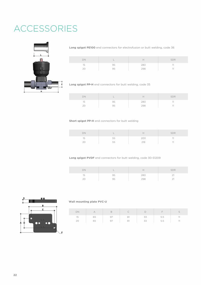
DN A B C D F S
15 65 97 81 33 5.5 11
20 65 97 81 33 5.5 11
Wall mounting plate PVC-U
ACCESSORIES
Long spigot PE100 end connectors for electrofusion or butt welding, code 36
Long spigot PP-H end connectors for butt welding, code 35
Short spigot PP-H end connectors for butt welding
Long spigot PVDF end connectors for butt welding, code 30-S1209
DN L H SDR
15 95 280 11
20 95 298 11
DN L H SDR
15 95 280 11
20 95 298 11
DN L H SDR
15 55 200 11
20 55 218 11
DN L H SDR
15 95 280 21
20 95 298 21
22

FASTENING AND SUPPORTING
CUSTOMIzATIONThe 382 DN 15-20 valve can be customized using a customization plate in white PVC.
The customization plate (B), housed in the transparent protection cap (A), can be removed and, once overturned, used for indicating identification serial numbers or service indications on the valves such as, for example, the valve function in the system, the conveyed fluid, but also specific information for customer service, such as the customer name or installation date or location on the valves. The waterproof transparent protection cap with seal O-Ring protect the customization plate against deterioration.
To access the customization plate, proceed as follows:
1) Disconnect the valve from the pneumatic connections
2) Unscrew the transparent protection cap (fig. 1)
3) Remove the plate and proceed with the customization (fig. 2).
4) Re-assemble everything making sure that the transparent protection cap O-Ring remains in its seating.
Fig. 1
Fig. 2
A
B
All valves, whether manual or actuated, must be adequately supported in many applications.
The new valve series is therefore provided with an integrated bracket that permits direct anchoring of the valve body without the need of other components.
For wall installation, dedicated wall mounting plates which are available as accessories can be used. These plates should be fastened to the valve before wall installation.
The wall mounting plate also allows the valve to be aligned with pipe clips.
d DN A L J
20 15 74 25 M6 x 10
25 20 74 25 M6 x 10
23

COMPONENTSEXPLoDED VIEW DN 15-20
DN 15 20
A 40 40
B 44 44
* Spare parts
** Accessories
The material of the component and the quantity supplied are indicated between brackets
1 Transparent cap (PC- 1)*
2 Customization plate (PVC - 1)
3 O-Ring (EPDM - 1)
4 Actuator (PP-GR - 1)*
6 Compressor (IXEF - 1)
7 Diaphragm seal (EPDM, FPM, PTFE - 1)*
8 Valve body (PVC-U, PVCC, PPH, PVDF – 1)*
9 Socket seal O-ring (EPDM-FPM - 2)*
10 End connector (PVC-U, PVCC, PPH, PVDF - 2)*
11 Union nut (PVC-U, PVCC, PPH, PVDF - 2)*
12 Washer (Stainless steel- 4)
13 Bolt (Stainless steel - 4)
14 Protection plug (PE - 4)
15 Distance plate (PP-GR - 1)**
16 Screw (Stainless steel - 2)**
24

Fig. 3
Fig. 4
DISASSEMBLy ASSEMBLy1) Isolate the valve from the line (re-
lease the pressure and empty the pipeline).
2) Open the valve with compressed air (NC-DA) to drain any residual liquid from the valve.
3) Disconnect the valve from the pneu-matic and electrical connections
4) Fully unscrew the union nuts (11) and extract the valve sideways.
5) Remove the protection plugs (14) and bolts (13) with their washers (12) (this operation will be made easier if the actuator is pressurised (NC).
6) Separate the valve body (8) from the actuator (4).
7) Unscrew the diaphragm (7) and remove the compressor (6) (this operation will be made easier if the actuator is not pressurised (NC).
1) Insert the compressor (6) on the ac-tuator stem (4) aligning it correctly in its housing (fig. 3).
2) Screw the diaphragm (7) onto the stem, aligning it correctly with its housing on the actuator.
3) Mount the actuator (4) on the valve body (8) and screw in the bolts (13) with the relative washers (12) (this operation will be made easier if the actuator is pressurised (NC).
4) Tighten the bolts (13) evenly (di-agonally) to the tightening torque suggested on the relative instruction sheet.
5 Replace the protection plugs (14) 6) Position the valve between the end
connectors (10) and tighten the un-ion nuts (11), making sure that the socket seal O-rings (9) do not exit their seats.
7) Reconnect the valve to the pneumat-ic and electrical connections
Note: All operations on equipment un-der pressure or containing compressed springs must be carried out under safe conditions for the operator.
INSTALLATIONBefore proceeding with installation. please follow these instructions carefully:(these instructions refer to union ends versions). The valve can be installed in any position and in any direction.
1) Check that the pipes to be connected to the valve are aligned in order to avoid mechanical stress on the threaded joints.
2) Unscrew the union nuts (11) and insert them on the pipe segments.
3) Solvent weld or screw the end connectors (10) onto the pipe ends.
4) Position the valve body between the end connectors, making sure that the sock-et seal O-rings (9) do not exit their seats.
5) Fully tighten the union nuts (11).
6) If necessary, support the pipework with pipe clips or by means of the carrier built into the valve itself (see paragraph “Fastening and supporting”).
7) Connect the compressed air as indicated in paragraph “Compressed air connec-tions”. For valves with electric accessories, refer to the specific technical manual supplied with the accessory.
When installing in confined spaces, the connections can be oriented in line with the piping (fig. 4).
Note: before putting the valve into service, check that the bolts on the valve body (8) are tightened correctly at the suggested torque.
25