31013 codognè (tv) italy è stato testato e collaudato ... · esquema eléctrico estándar pág...
TRANSCRIPT
1
ATTENTION! Before installing this device read the following instructions carefully!
Installation example Pag. 2Important remarks Pag. 10 Preliminary assembly operations Pag. 11Installation Pag. 11Manual manoeuvre Pag. 11Electronic programmer Pag. 12Indications on the display Pag. 13Function modes Pag. 13Programming procedure Pag. 14-15Remote control Pag. 16Standard wiring diagram Pag. 42Standards and approvals certification Pag. 43Technical specifications Pag. 44
ACHTUNG! Bevor mit der Installation begonnen wird, sollte die Anleitung aufmerksam gelesen werden.
Anlagenart Seite 2Wichtige Hinweise Seite 24Vorbereitende Montagearbeiten Seite 25Installation Seite 25Manuelle Betätigung Seite 25Elektronischer Programmierer Seite 26Anzeigen Display Seite 27Betriebsarten Seite 27Programmierung Seite 28-29Funksteuerung Seite 30Elektrischer Schaltplan Anlagenart Seite 42Bestimmungen und Zertifikate Seite 43Technische Daten Seite 44
AUTOMAZIONE A TRAINO PER PORTE SEZIONALI E BASCULANTI CHAIN GUIDED AUTOMATION FOR FOLD UP AND OVERHEAD GARAGE DOORS
AUTOMATISME PAR ENTRAÎNEMENT POUR PORTES SECTIONNALES ET BASCULANTESAUTOMATISIERUNG PER ZUG FÜR SEKTIONALTORE UND KIPPTORE
AUTOMATIZACIÓN DE ARRASTRE PARA PUERTAS PLEGABLES Y BASCULANTES
¡ATENCIÓN! Antes de iniciar la instalación del sistema, leer atentamente las instrucciones.
Instalación estándar Pág. 2Advertencias importantes Pág. 31Operaciones previas al montaje Pág. 32Instalación Pág. 32Maniobra manual Pág. 32Programador electrónico Pág. 33Indicaciones en el display Pág. 34Modalidad de funcionamiento Pág. 34Procedimiento para la programación Pág. 35-36Mando vía radio Pág. 37Esquema eléctrico estándar Pág. 42Normas y certificación Pág. 43Datos técnicos Pág. 44
ZV
L323
.05
Mod
: 11-
06-2
013
ATTENZIONE! Prima di iniziare l'installazione leggere le istruzioni attentamente!
Impianto tipo Pag. 2 Avvertenze importanti Pag. 3 Operazioni preliminari di montaggio Pag. 4Installazione Pag. 4Manovra manuale Pag. 4Programmatore elettronico Pag. 5Indicazioni del display Pag. 6Modalità di funzionamento Pag. 6Procedura di programmazione Pag. 7-8Comando via radio Pag. 9Schema elettrico impianto tipo Pag. 42Norme e certificazione Pag. 43Caratteristiche tecniche Pag. 44
ATTENTION! Avant de commencer la pose, lire attentive-ment les instructions!
Exemple d’installation Pag. 2Conseils importants Pag. 17Préparation avant le montage Pag. 18Installation Pag. 18Manœuvre manuelle Pag. 18Programmateur électronique Pag. 19Indications de l’afficheur Pag. 20Modes de fonctionnement Pag. 20Procédé de programmation Pag. 21-22Commande par radio Pag. 23Schéma électrique de l'exemple d'installation Pag. 42Normes et certificats Pag. 43Caractéristiques techniques Pag. 44
ITALIANO
ENGLISH ESPAÑOL
DEUTSCH
FRANÇAIS
24Vdc Motors GL112409
GL24VdcMotors
Questo prodotto è stato testato e collaudato nei laboratori della casa costruttrice, la quale ne ha verificato la perfetta corrispondenza delle caratteristiche con quelle richieste dalla normativa vigente. This product has been tried and tested in the manufacturer's laboratory who have verified that the product conforms in every aspect to the safety standards in force. Ce produit a été testé et essayé dans les laboratoires du fabriquant. Pour l'installer suivre attentivement les instructions fournies. Dieses Produkt wurde in den Werkstätten der Herstellerfirma auf die perfekte Übereinstimmung ihrer Eigenschaften mit den von den geltenden Normen vorgeschriebenen getestet und geprüft. Este producto ha sido probado y ensayado en los laboratorios del fabricante, que ha comprobado la perfecta correspondencia de sus características con las contempladas por la normativa vigente.
Model DateInstruction manual Series
GL 112409 25-02-2004ZVL323.05CARDIN ELETTRONICA spa Via del lavoro, 73 – Z.I. Cimavilla 31013 Codognè (TV) I ta lyTel: +39/0438.404011Fax: +39/0438.401831email (Italian): [email protected] (Europe): [email protected]: www.cardin.it
2
SC
ALA
:
pro
do
tti Technocity (lam
p. fo
tocellule ecc.)
GL1124
11-03-2004
DI0456
Descrip
tion :
Prod
uct Cod
e :
Date :
Draw
ing numb
er :
P.J.Heath
CA
RD
IN E
LET
TR
ON
ICA
S.p
.A - 31020 S
an Vendem
iano (T
V) Italy - via R
affaello, 36 Tel: 0438/401818 F
ax: 0438/401831
Draft :
All rig
hts reserved. U
nauthorised
cop
ying o
r use of the info
rmatio
n contained
in this do
cument is p
unishable b
y law
INS
TALLA
ZIO
NE
TIP
O G
L1124
RX
230V - 50Hz
TX
2
12
4
9
7
11
12
5
10
8
1
3
6
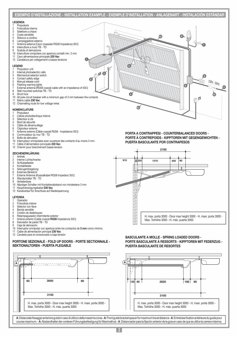
LEGENDA1 Propulsore2 Fotocellula interna3 Selettore a chiave 4 Costa sensibile 5 Sblocco a cordino6 Lampeggiatore esterno7 Antenna esterna (Cavo coassiale RG58 Impedenza 50Ω)8 Interruttore a muro TB - TD9 Scatola di derivazione10 Interruttore onnipolare con apertura contatti min. 3 mm11 Cavo alimentazione principale 230 Vac12 Canalatura per collegamenti a bassa tensione
LEGEND1 Propulsion unit2 Internal photoelectric cells3 Mechanical selector switch4 Contact safety edge5 Manual release cord6 Flashing warning lights7 External antenna (RG58 coaxial cable with an impedance of 50Ω)8 Wall mounted switches TB - TD9 Shunt box10 All pole circuit breaker with a minimum gap of 3 mm between the contacts11 Mains cable 230 Vac12 Channelling route for low voltage wires
NOMENCLATURE1 Propulseur2 Cellule photoélectrique interne3 Sélecteur à clé4 Bord de sécurité5 Câble de déverrouillage6 Clignoteur externe7 Antenne externe (Câble coaxial RG58 - Impédance 50Ω)8 Commutateur du mur TB - TD9 Boîte de dérivation10 Interrupteur omnipolaire avec ouverture des contacts d'au moins 3 mm.11 Câble d’alimentation principale 230 Vac12 Chemin pour branchement basse tension
ZEICHENERKLÄRUNG1 Antrieb2 Interne Lichtschranke3 Schlüsseltaster4 Kontaktleiste5 Seilzugentriegelung6 Externes Blinklicht7 Externe Antenne (Koaxialkabel RG58 Impedanz 50Ω) 8 Wandschalter TB - TD9 Verteilerdose10 Allpoliger Schalter mit Kontaktenabstand von mindestens 3 mm11 Hauptversorgungskabel 230 Vac12 Kanalverlauf für Anschluss auf Niederspannung
LEYENDA1 Operador2 Fotocélula interior3 Selector con llave4 Banda sensible5 Cordón de desbloqueo6 Relampagueador intermitente exterior7 Antena exterior (Cable coaxial RG58 Impedancia 50Ω)8 Desviador de pared TB - TD9 Caja de derivación10 Interruptor omnipolar con apertura entre los contactos de 3 mm como mínimo.11 Cable de alimentación principal 230 Vac12 Canaleta para el conexionado a baja tensión
250 1310 450 90
2100
30910
SCALA: 1:2
Prodotti Technocity
GL1024 (traino)
06-04-98
DI0058 Description :
Product Code :
Date :
Drawing number :
P.J.Heath
CARDIN ELETTRONICA S.p.A - 31020 San Vendemiano (TV) Italy - via Raffaello, 36 Tel: 0438/401818 Fax: 0438/401831
Draft :
All rights reserved. Unauthorised copying or use of the information contained in this document is punishable by law
INSTALLAZIONE PORTA A CONTRAPPESI
ESEMPIO D'INSTALLAZIONE PORTA A MOLLE
60 2820 180 90
3150
120
SCALA: 1:2
prodotti Technocity
GL1024 (traino)
30-11-98
DI0056 Description :
Product Code :
Date :
Drawing number :
P.J.Heath
CARDIN ELETTRONICA S.p.A - 31020 San Vendemiano (TV) Italy - via Raffaello, 36 Tel: 0438/401818 Fax: 0438/401831
Draft :
All rights reserved. Unauthorised copying or use of the information contained in this document is punishable by law
INSTALLAZIONE PORTA A MOLLE
A
ESEMPIO D'INSTALLAZIONE PORTA SEZIONALE
60 3000 90
3150
SCALA: 1:2
Prodotti Technocity
GL1024 (traino)
06-04-98
DI0057 Description :
Product Code :
Date :
Drawing number :
P.J.Heath
CARDIN ELETTRONICA S.p.A - 31020 San Vendemiano (TV) Italy - via Raffaello, 36 Tel: 0438/401818 Fax: 0438/401831
Draft :
All rights reserved. Unauthorised copying or use of the information contained in this document is punishable by law
INSTALLAZIONE PORTA SEZIONALE
A
PORTA A CONTRAPPESI - COUNTERBALANCED DOORS -PORTE À CONTREPOIDS - KIPPTOREN MIT GEGENGEWICHTEN -PUERTA BASCULANTE POR CONTRAPESOS
PORTONE SEZIONALE - FOLD UP DOORS - PORTE SECTIONNALE -SEKTIONALTOREN - PUERTA PLEGABLE
BASCULANTE A MOLLE - SPRING LOADED DOORS -PORTE BASCULANTE À RESSORTS - KIPPTOREN MIT FEDERZUG -PUERTA BASCULANTE DE RESORTES
ESEMPIO D'INSTALLAZIONE - INSTALLATION EXAMPLE - EXEMPLE D'INSTALLATION - ANLAGENART - INSTALACIÓN ESTÁNDAR
A: Distanziale fissaggio anteriore guida in caso di utilizzo della massima corsa - A: Front guide bracket spacer for maximum travel distance - A: Entretoise fixation antérieure du guide pour course maximum. - A: Abstandhalter der vorderen Führungsbefestigung für Maximalhub - A: Distanciador para la fijación anterior de la guía en caso de que se utilice la carrera máxima.
H. max. porta 3000 - Door max height 3000 - H. maxi. porte 3000 -Max. Torhöhe 3000 - H. máx. puerta 3000
H. max. porta 3000 - Door max height 3000 - H. maxi. porte 3000 -Max. Torhöhe 3000 - H. máx. puerta 3000
H. max. porta 3000 - Door max height 3000 - H. maxi. porte 3000 -Max. Torhöhe 3000 - H. máx. puerta 3000

3
• Il presente manuale si rivolge a persone abilitate all'installazione di "APPA-RECCHI UTILIZZATORI DI ENERGIA ELETTRICA" e richiede una buona conoscenza della tecnica, esercitata in forma professionale. I materiali usati devono essere certificati e risultare idonei alle condizioni ambientali di installazione.
• Le operazioni di manutenzione devono essere eseguite da personale quali-ficato. Prima di eseguire qualsiasi operazione di pulizia o di manutenzione, disinserire l'apparecchiatura dalla rete di alimentazione elettrica.
• Le apparecchiature qui descritte dovranno essere destinate solo all'uso per il quale sono state espressamente concepite:
"La motorizzazione di porte sezionali e basculanti". L’utilizzo dei prodotti e la loro destinazione ad usi diversi da quelli previsti
e/o consigliati, non è stata sperimentata dal costruttore, pertanto i lavori eseguiti sono sotto la completa responsabilità dell’installatore.
• Il programmatore è dotato di un controllo sulla corrente assorbita dal motore, utilizzato per bloccare il moto in condizioni di emergenza; tale controllo non viene però fatto:
- nei primi 5 secondi della fase di apertura da ‘completamente chiuso’ - nei 2.5 secondi iniziali di ogni altro movimento Evitare pertanto di fare resistenza sull’anta in tali fasi, in caso contrario
potrebbe saltare il fusibile "F3" del circuito motore.• Dopo aver installato il dispositivo (e prima di dare tensione alla centralina)
procedere come segue: verificare che il movimento dell’anta eseguito in modo manuale non abbia punti di resistenza particolarmente marcata, quindi agganciare il carrello al pattino di traino verificando che il finecorsa di apertura sia attivato dal carrello.
• Dare tensione alla centralina: se il finecorsa è effettivamente attivato, sul display compare un trattino lampeggiante, indicante che il sistema è nella fase di pausa per la richiusura automatica. Azionare a uomo presente l'anta, mandandola in chiusura premendo il tasto "SEL". Il moto dura fintanto che il tasto è premuto, e cessa al suo rilascio.
Nota: Se durante la chiusura a uomo presente si preme anche il tasto "PROG", dopo la pausa d'inversione il moto riprenderà in apertura. Per ulteriori chiarimenti vedere a pagina 6, "modalità uomo presente".
Attenzione! Le uniche sicurezze che possono bloccare il moto a uomo presente sono il tasto di blocco ed i finecorsa. Appena l'anta arriva alla completa chiusura, rilasciare il tasto "SEL": non forzare ulteriormente la chiusura.Attenzione! verificare sempre che la catena sia agganciata al carrello di traino prima di procedere alla programmazione, e che il portone sia completamente chiuso.
• Si è ora pronti per la programmazione del sistema, come descritto nel paragrafo "Procedura di programmazione" (pag.7, 8).
Nota: Nel caso si debba verificare lo stato del fusibile " F2", scollegare prima l'alimentazione dal programmatore; ripristinarla solo dopo aver inserito il fusibile. Non escludere mai i finecorsa (vedere "procedura di programma-zione" nota 2, pag.7) e verificare che il finecorsa di apertura sia sempre collegato. Il rallentamento deve essere escluso per i portoni sezionali (vedere "procedura di programmazione" nota 3, pag.7).
Attenzione! La presenza del sensore di corrente non elimina l’obbligo di installare le fotocellule o altri dispositivi di sicurezza previsti dalle normative vigenti.
Possibilità d'impiegoIl gruppo motore GL112409 movimenta basculanti a molle, porte sezionali, basculanti a contrappesi a totale o parziale rientranza, con telo porta h max 3m e L max 3,5m e peso max 70kg. Scegliere in base al tipo di porta il kit da utilizzare (vedi accessori).
Descrizione tecnica- Motore alimentato a 24 Vdc.- Cassa del riduttore in alluminio pressofuso. All'interno opera un sistema
di riduzione a vite senza fine e ruota a denti elicoidali in materiale termoplastico con lubrificazione a grasso fluido.
- Contenitore per catena costituito da due scocche in materiale plastico che inglobano il percorso di accumulo della catena e la tengono separata dalle parti elettroniche.
- Programmatore elettronico con ricevente radio incorporata.- Luce di cortesia (E14 - 230 Vac - 40 W)- Coperchio in materiale plastico antiurto e plafoniera in plastica opalina.
Accessori 320/GL1124BKit per traino basculante a contrappesi completo di guida carrello lunghezza 2100 mm. e braccio curvo adattatore "9"-"11" (fig.6).320/GL1124SKit per traino basculante a molle / portone sezionale con guida carrello lun-ghezza 3150 mm, leva curva "10" (fig. 5) e coppia lame forate "5" (fig.3).316/GL20SBSblocco a cordino.
Attenzione! Solo per clienti dell’EU - Marcatura WEEE.Il simbolo indica che il prodotto alla fine della propria vita utile deve essere raccolto separatamente dagli altri rifiuti. L’utente dovrà pertanto conferire l’apparecchiatura agli idonei centri di raccolta differenziata dei rifiuti elettronici ed elettrici, oppure riconsegnarla al rivenditore al momento dell’acquisto di una nuova apparecchiatura di tipo equivalente, in ragione di uno a uno.
L’adeguata raccolta differenziata per l’avvio al riciclaggio, al trattamento e allo smaltimento ambientalmente compatibile contribuisce ad evitare possibili effetti negativi sull’ambiente e sulla salute e favorisce il riciclo dei materiali.Lo smaltimento abusivo del prodotto da parte del detentore comporta l’ap-plicazione delle sanzioni amministrative previste dalla normativa vigente nello Stato Comunitario di appartenenza.
Importante! Prima di effettuare l'installazione verificare che la struttura da automatizzare sia in perfetta efficienza nelle sue parti fisse e mobili e realizzata in conformità alle normativa vigente. A tal fine accertarsi della sufficiente rigidità del telo porta (rinforzare la struttura se necessario), del bilanciamento e del buon scorrimento delle guide (lubrificare tutte le parti in movimento). Verificare che la minima distanza tra il punto più alto della traiettoria d’aper-tura della porta e il soffitto non sia inferiore a 60 mm (fig. 1).
Attenzione! La guida deve essere montata tra 10 e 20 mm sopra il bordo superiore della porta, tale posizione garantisce un funzionamento ottimale ed è indispensabile affinché la porta non vada mai ad urtare contro la guida durante il normale fun-zionamento (fig. 1 dett. A).
MINIMA DISTANZA TRA IL SOFFITTO ED IL PUNTO PIÙ ALTO DELLA TRAIETTORIA
60 mm60 mm 60 mm
SCALA: 1:2
Prodotti Technocity
GL1024 (traino)
06-04-98
DI0059 Description :
Product Code :
Date :
Drawing number :
P.J.Heath
CARDIN ELETTRONICA S.p.A - 31020 San Vendemiano (TV) Italy - via Raffaello, 36 Tel: 0438/401818 Fax: 0438/401831
Draft :
All rights reserved. Unauthorised copying or use of the information contained in this document is punishable by law
Distanze tra il soffitto e la porta
Basculante a molle Portone sezionaleBasculante a contrappesi
10 - 20 mm
A
SCALA: 1:2
Prodotti Technocity
GL1024 (traino)
26-01-2000
DI0142 Description :
Product Code :
Date :
Drawing number :
P.J.Heath
CARDIN ELETTRONICA S.p.A - 31020 San Vendemiano (TV) Italy - via Raffaello, 36 Tel: 0438/401818 Fax: 0438/401831
Draft :
All rights reserved. Unauthorised copying or use of the information contained in this document is punishable by law
INSTALLAZIONE PORTA A CONTRAPPESI spazio di 10 mm
1
AVVERTENZE IMPORTANTI AVVERTENZE IMPORTANTI AVVERTENZE IMPORTANTI LEGGERE ATTENTAMENTE LE SEGUENTI AVVERTENZE PRIMA DI PROCEDERE ALL’INSTALLAZIONE. PRE-STARE PARTICOLARE ATTENZIONE A TUTTE LE SEGNALAZIONI DISPOSTE NEL TESTO. IL MANCATO RISPETTO DI QUESTE POTREBBE COMPROMETTERE IL BUON FUNZIONAMENTO DEL SISTEMA E CREARE SITUAZIONI DI PERICOLO GRAVE PER L'OPERATORE E GLI UTILIZZATORI DEL SISTEMA STESSO.
AVVERTENZE PER L'UTENTE

4
• La guida deve essere montata per-pendicolare alla porta e parallela al soffitto.
• Marcare l'esatta metà della porta e tracciare, perpendicolarmente alla porta, un segno sul soffitto per faci-litare il posizionamento della guida.
• Fissare le squadrette anteriori della guida alla traversa superiore fissa della porta, utilizzando viti M6 o autofilettanti 6,3 x 19 (fig. 4).
• Segnare la posizione dei punti di fissaggio delle lame forate supporto guida posteriori "5" (fig. 4) ed eventuali centrali "5a" (fig. 4) al soffitto, riferendosi al segno sul soffitto fatto in precedenza. Forare con punta da 10 per tasselli da muro.
• Fissare, perpendicolarmente al soffitto, le lame forate supporto guida con viti M6.
• Serrare le viti anteriori di fissaggio guida.• Sbloccare il carrello di traino con un leggero tiro e farlo scorrere sulla
guida fino a portarlo sulla parte anteriore, vicino alla porta.
Quindi, a seconda dei casi:
A) Portone sezionale, basculante a molle (fig. 5)• Fissare la squadretta di traino "8" sulla parte
superiore della porta, sulla mezzeria preceden-temente determinata, con 6 viti autofilettanti 4,9 x 19 o rivetti.
• Collegare la leva curva "10" alla squadretta di traino e al carrello di traino "8" mediante perno e anelli d'arresto in dotazione. Per utilizzare al massimo la corsa del carrello può essere necessario, a seconda dei casi, accorciare tale leva sfruttando la foratura prevista e spostare l'inizio della guida (aumentare la quota "A" fig. 4 con apposito distanziale).
B) Basculante a contrappesi (fig. 6)• Fissare il braccio curvo adattatore "9" in mezze-
ria e tassativamente a filo con la parte superiore della porta "12", con 4+4 viti autofilettanti 4,9 x 19.
Qualora il punto inferiore di fissaggio non coincida con una traversa "13" della struttura porta aggiungere un rinforzo "14"
• Collegare il piatto forato "11" al carrello di traino tramite perno e anelli d'arresto in dotazione e al braccio curvo adattatore "9" tramite due viti M8 x 20 con relativi dadi.
• Verificare il corretto funzionamento: alla corsa del carrello deve corrispondere la completa apertura della porta.
• Verificare la bilanciatura della porta (a motore sbloccato la porta deve rimanere ferma, in equilibrio, in qualunque punto di apertura).
ManutenzioniVerifica periodica delle parti in movimento (perni, funi) con eventuale lubrificazione.
Importante! La guida in alluminio è fornita alle misure standard (vedi accessori). Qualora si richieda una misura inferiore comportante il taglio della guida è vietato accoppiare il lato tagliato con l’operatore.
1. Inserire il cursore "A", la catena e i piatti di supporto "C" nell'apposito vano " " della guida "B".
2. Portare la guida "B" in battuta alla testa dell'operatore "D", usando un martello in gomma "E". Togliere i trucioli (tra testa guida e base in plastica) che si accumulano durante l’inserimento della guida.
Attenzione! Non vi deve essere discontinuità sul percorso della catena tra l’operatore e la guida in alluminio.
3. Montare le quattro viti e rondelle "L" e serrare a fondo.4. Inserire il carrello di traino "F" nella guida "B" fino ad aggan-
ciarlo al cursore "A", con il piatto forato rivolto verso la parte opposta all'operatore "D".
5. Fissare il supporto microinterruttore di fine corsa "G" alla guida "B" (vedi parti-colare aggancio). Sarà possibile in seguito farlo slittare fino al punto desiderato.
Montaggio guida (fig. 3)• Posizionare le squadrette anteriori di fissaggio guida "4", unendole alle
relative piastrine (inserite nelle apposite scanalature della guida), con le viti in dotazione.
• Montare le lame forate supporto guida "5" posizionandole sulle viti fis-saggio attuatore "L" (fig. 2) alla guida e utilizzando le apposite piastrine "10" nella posizione intermedia (circa 1/3 avanti).
• Fissare il cordino con pomello di sblocco "E" all'elemento di aggancio/sgancio del carrello (fig. 3a).
• Eliminare il sistema di chiusura della porta sostituendolo con lo sblocco a cordino (fig. 3a).
10
7 8
SCALA: 1:2
Prodotti Technocity
GL1024 (traino)
07-04-98
DI0061 Description :
Product Code :
Date :
Drawing number :
P.J.Heath
CARDIN ELETTRONICA S.p.A - 31020 San Vendemiano (TV) Italy - via Raffaello, 36 Tel: 0438/401818 Fax: 0438/401831
Draft :
All rights reserved. Unauthorised copying or use of the information contained in this document is punishable by law
INSTALLAZIONE PORTONE SEZIONALE/BASCULANTE A MOLLA
montaggio motore
GL1124
19-10-98
DM0380 Description :
Product Code :
Date :
Drawing number :
P.J.Heath
CARDIN ELETTRONICA S.p.A - 31020 San Vendemiano (TV) Italy - via Raffaello, 36 Tel: 0438/401818 Fax: 0438/401831
Draft :
All rights reserved. Unauthorised copying or use of the information contained in this document is punishable by law
GL1124
1
4
5
2
93
10
8
7
4
6
2
5
10
11
5
55
SCALA: 1:2
Prodotti Technocity
GL1024 (traino)
07-04-98
DI0062 Description :
Product Code :
Date :
Drawing number :
P.J.Heath
CARDIN ELETTRONICA S.p.A - 31020 San Vendemiano (TV) Italy - via Raffaello, 36 Tel: 0438/401818 Fax: 0438/401831
Draft :
All rights reserved. Unauthorised copying or use of the information contained in this document is punishable by law
INSTALLAZIONE BASCULANTE A TOTALE O PARZIALE RIENTRANCE
30 mm min
9
11
12
14
13
A
SCALA: 1:2
Prodotti Technocity
GL1024 (traino)
06-04-98
DI0060 Description :
Product Code :
Date :
Drawing number :
P.J.Heath
CARDIN ELETTRONICA S.p.A - 31020 San Vendemiano (TV) Italy - via Raffaello, 36 Tel: 0438/401818 Fax: 0438/401831
Draft :
All rights reserved. Unauthorised copying or use of the information contained in this document is punishable by law
INSTALLAZIONE A SOFFITTO
5
5a
montaggio motore preliminari
GL1024
21-05-98
DM0368 Description :
Product Code :
Date :
Drawing number :
P.J.Heath
CARDIN ELETTRONICA S.p.A - 31020 San Vendemiano (TV) Italy - via Raffaello, 36 Tel: 0438/401818 Fax: 0438/401831
Draft :
All rights reserved. Unauthorised copying or use of the information contained in this document is punishable by law
GL1024
B
G2ACD
F
E
L
G1
6
MANOVRA MANUALE
4
3
5
2
OPERAZIONI PRELIMINARI DI MONTAGGIO
Particolare aggancio supporto finecorsa
INSTALLAZIONE
Il motoriduttore è del tipo irreversibile e garantisce il bloccaggio della porta in chiusura. Per lo sblocco, da attuarsi in assenza di energia elettrica procedere come segue: • Tirare il cordino verso la porta come indicato in figura 7; il motore si sblocca e la porta può essere manovrata manualmente.Attenzione! Non usare il cordino per muovere la porta bensì usare sempre la maniglia della porta stessa. • Per ribloccare il motore tirare il cordino nella dire-zione opposta come indicato in figura 8 e poi chiudere la porta. Lo sblocco si riarma automaticamente.
7 8
5 Lama forata supporto guida6 Guida per sezionale lungh. 3150 mm7 Leva curva 8 Squadretta di traino9 Braccio curvo adattatore 10 Piastrine di fissaggio11 Foro ingresso cavi
100
mm
ED
A
B
C
E
PREMONTAGGIO
GL1024
06-04-98
DM0353 Description :
Product Code :
Date :
Drawing number :
P.J.Heath
CARDIN ELETTRONICA S.p.A - 31020 San Vendemiano (TV) Italy - via Raffaello, 36 Tel: 0438/401818 Fax: 0438/401831
Draft :
All rights reserved. Unauthorised copying or use of the information contained in this document is punishable by law
GL1024 SBLOCCO A CORDINO
3a
Legenda1 Attuatore elettromeccanico 24V con programmatore2 Carrello di traino3 Guida per basculante a contrappesi lungh. 2100 mm4 Squadrette anteriori fissaggio guida
5
Programmatore per motore in corrente continua con ricevente incorporata, che permette la memorizzazione di 300 codici utente (vedere "comando via radio", a pag. 9). La decodifica è di tipo 'rolling code', e la frequenza di funzionamento è di 433,92 MHz. La velocità di trascinamento è controllata elettronicamente, con partenza lenta e successivo incremento; la velocità viene ridotta con anticipo rispetto all'arrivo a finecorsa, in modo da ottenere un arresto controllato (se il rallentamento non viene escluso nella procedura di programmazione). La programmazione, eseguibile mediante due soli pulsanti, permette la configurazione del sistema, della durata della fase di rallentamento, del sensore di sforzo e dei tempi di lavoro-pausa.L’intervento del sensore antischiacciamento/anticonvogliamento in fase di chiusura causa l’inversione del moto e lo stesso avviene nella fase di apertura (se la richiusura automatica è abilitata: in caso contrario causa il blocco). Se il moto è nella fase terminale, invece, il sensore agisce come finecorsa.
COLLEGAMENTO ELETTRICO• Aprire lo "Schema elettrico impianto tipo" piegato all'interno dell'ultima
pagina del presente libretto e procedere con la programmazione.
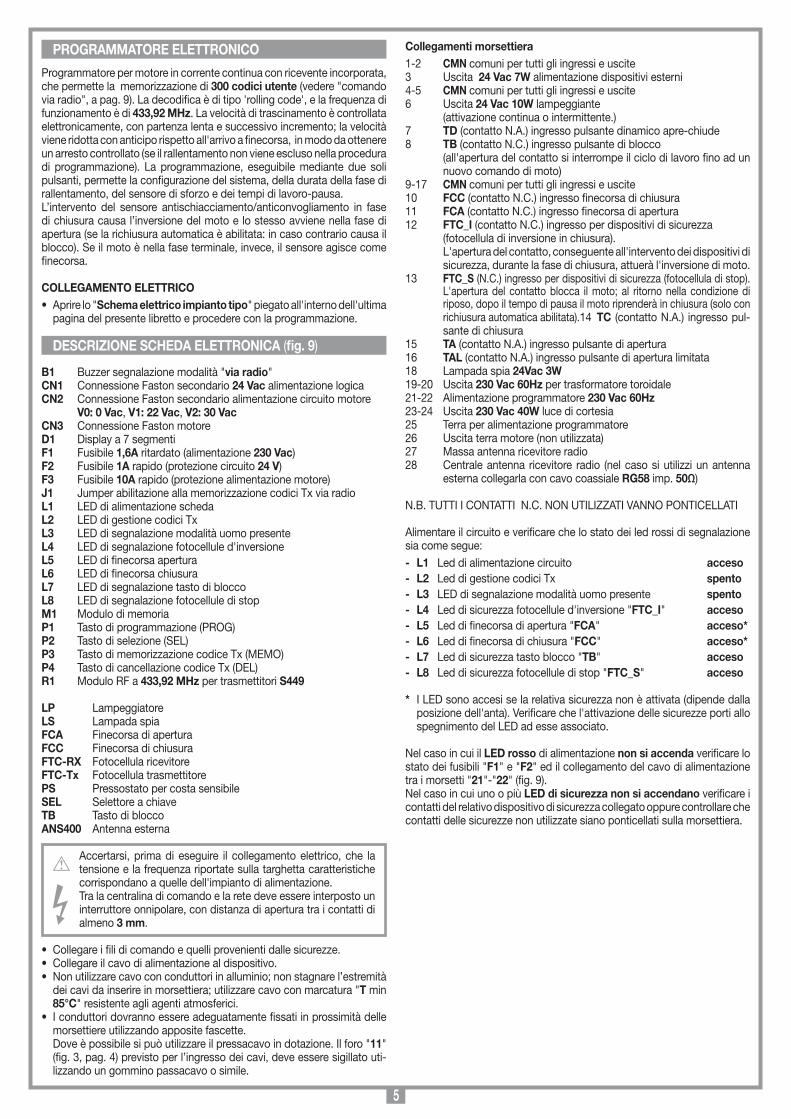
B1 Buzzer segnalazione modalità "via radio"CN1 Connessione Faston secondario 24 Vac alimentazione logicaCN2 Connessione Faston secondario alimentazione circuito motore V0: 0 Vac, V1: 22 Vac, V2: 30 VacCN3 Connessione Faston motore D1 Display a 7 segmentiF1 Fusibile 1,6A ritardato (alimentazione 230 Vac) F2 Fusibile 1A rapido (protezione circuito 24 V) F3 Fusibile 10A rapido (protezione alimentazione motore) J1 Jumper abilitazione alla memorizzazione codici Tx via radioL1 LED di alimentazione schedaL2 LED di gestione codici TxL3 LED di segnalazione modalità uomo presenteL4 LED di segnalazione fotocellule d'inversioneL5 LED di finecorsa aperturaL6 LED di finecorsa chiusuraL7 LED di segnalazione tasto di bloccoL8 LED di segnalazione fotocellule di stopM1 Modulo di memoriaP1 Tasto di programmazione (PROG)P2 Tasto di selezione (SEL)P3 Tasto di memorizzazione codice Tx (MEMO) P4 Tasto di cancellazione codice Tx (DEL)R1 Modulo RF a 433,92 MHz per trasmettitori S449
LP LampeggiatoreLS Lampada spiaFCA Finecorsa di aperturaFCC Finecorsa di chiusuraFTC-RX Fotocellula ricevitoreFTC-Tx Fotocellula trasmettitorePS Pressostato per costa sensibileSEL Selettore a chiaveTB Tasto di bloccoANS400 Antenna esterna
Accertarsi, prima di eseguire il collegamento elettrico, che la tensione e la frequenza riportate sulla targhetta caratteristiche corrispondano a quelle dell'impianto di alimentazione.Tra la centralina di comando e la rete deve essere interposto un interruttore onnipolare, con distanza di apertura tra i contatti di almeno 3 mm.
• Collegare i fili di comando e quelli provenienti dalle sicurezze.• Collegare il cavo di alimentazione al dispositivo.• Non utilizzare cavo con conduttori in alluminio; non stagnare l’estremità
dei cavi da inserire in morsettiera; utilizzare cavo con marcatura "T min 85°C" resistente agli agenti atmosferici.
• I conduttori dovranno essere adeguatamente fissati in prossimità delle morsettiere utilizzando apposite fascette.
Dove è possibile si può utilizzare il pressacavo in dotazione. Il foro "11" (fig. 3, pag. 4) previsto per l’ingresso dei cavi, deve essere sigillato uti-lizzando un gommino passacavo o simile.
Collegamenti morsettiera1-2 CMN comuni per tutti gli ingressi e uscite3 Uscita 24 Vac 7W alimentazione dispositivi esterni4-5 CMN comuni per tutti gli ingressi e uscite6 Uscita 24 Vac 10W lampeggiante (attivazione continua o intermittente.)7 TD (contatto N.A.) ingresso pulsante dinamico apre-chiude8 TB (contatto N.C.) ingresso pulsante di blocco (all'apertura del contatto si interrompe il ciclo di lavoro fino ad un
nuovo comando di moto)9-17 CMN comuni per tutti gli ingressi e uscite 10 FCC (contatto N.C.) ingresso finecorsa di chiusura 11 FCA (contatto N.C.) ingresso finecorsa di apertura12 FTC_I (contatto N.C.) ingresso per dispositivi di sicurezza (fotocellula di inversione in chiusura). L'apertura del contatto, conseguente all'intervento dei dispositivi di
sicurezza, durante la fase di chiusura, attuerà l'inversione di moto.13 FTC_S (N.C.) ingresso per dispositivi di sicurezza (fotocellula di stop).
L'apertura del contatto blocca il moto; al ritorno nella condizione di riposo, dopo il tempo di pausa il moto riprenderà in chiusura (solo con richiusura automatica abilitata).14 TC (contatto N.A.) ingresso pul-sante di chiusura
15 TA (contatto N.A.) ingresso pulsante di apertura16 TAL (contatto N.A.) ingresso pulsante di apertura limitata 18 Lampada spia 24Vac 3W19-20 Uscita 230 Vac 60Hz per trasformatore toroidale21-22 Alimentazione programmatore 230 Vac 60Hz23-24 Uscita 230 Vac 40W luce di cortesia25 Terra per alimentazione programmatore26 Uscita terra motore (non utilizzata)27 Massa antenna ricevitore radio 28 Centrale antenna ricevitore radio (nel caso si utilizzi un antenna
esterna collegarla con cavo coassiale RG58 imp. 50Ω)
N.B. TUTTI I CONTATTI N.C. NON UTILIZZATI VANNO PONTICELLATI
Alimentare il circuito e verificare che lo stato dei led rossi di segnalazione sia come segue:- L1 Led di alimentazione circuito acceso- L2 Led di gestione codici Tx spento- L3 LED di segnalazione modalità uomo presente spento- L4 Led di sicurezza fotocellule d'inversione "FTC_I" acceso- L5 Led di finecorsa di apertura "FCA" acceso*- L6 Led di finecorsa di chiusura "FCC" acceso*- L7 Led di sicurezza tasto blocco "TB" acceso- L8 Led di sicurezza fotocellule di stop "FTC_S" acceso
* I LED sono accesi se la relativa sicurezza non è attivata (dipende dalla posizione dell'anta). Verificare che l'attivazione delle sicurezze porti allo spegnimento del LED ad esse associato.
Nel caso in cui il LED rosso di alimentazione non si accenda verificare lo stato dei fusibili "F1" e "F2" ed il collegamento del cavo di alimentazione tra i morsetti "21"-"22" (fig. 9).Nel caso in cui uno o più LED di sicurezza non si accendano verificare i contatti del relativo dispositivo di sicurezza collegato oppure controllare che contatti delle sicurezze non utilizzate siano ponticellati sulla morsettiera.
DESCRIZIONE SCHEDA ELETTRONICA (fig. 9)
PROGRAMMATORE ELETTRONICO
6
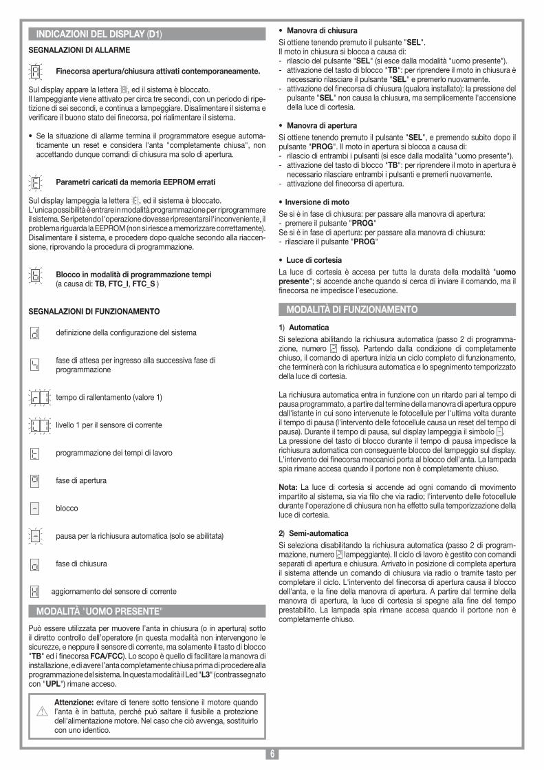
SEGNALAZIONI DI ALLARME
Finecorsa apertura/chiusura attivati contemporaneamente.
Sul display appare la lettera , ed il sistema è bloccato.Il lampeggiante viene attivato per circa tre secondi, con un periodo di ripe-tizione di sei secondi, e continua a lampeggiare. Disalimentare il sistema e verificare il buono stato dei finecorsa, poi rialimentare il sistema.
• Se la situazione di allarme termina il programmatore esegue automa-ticamente un reset e considera l'anta "completamente chiusa", non accettando dunque comandi di chiusura ma solo di apertura.
Parametri caricati da memoria EEPROM errati
Sul display lampeggia la lettera , ed il sistema è bloccato.L'unica possibilità è entrare in modalità programmazione per riprogrammare il sistema. Se ripetendo l'operazione dovesse ripresentarsi l'inconveniente, il problema riguarda la EEPROM (non si riesce a memorizzare correttamente). Disalimentare il sistema, e procedere dopo qualche secondo alla riaccen-sione, riprovando la procedura di programmazione.
Blocco in modalità di programmazione tempi (a causa di: TB, FTC_I, FTC_S )
SEGNALAZIONI DI FUNZIONAMENTO
definizione della configurazione del sistema
fase di attesa per ingresso alla successiva fase di programmazione
tempo di rallentamento (valore 1)
livello 1 per il sensore di corrente
programmazione dei tempi di lavoro
fase di apertura blocco
pausa per la richiusura automatica (solo se abilitata) fase di chiusura
aggiornamento del sensore di corrente
Può essere utilizzata per muovere l’anta in chiusura (o in apertura) sotto il diretto controllo dell’operatore (in questa modalità non intervengono le sicurezze, e neppure il sensore di corrente, ma solamente il tasto di blocco "TB" ed i finecorsa FCA/FCC). Lo scopo è quello di facilitare la manovra di installazione, e di avere l’anta completamente chiusa prima di procedere alla programmazione del sistema. In questa modalità il Led "L3" (contrassegnato con "UPL") rimane acceso.
Attenzione: evitare di tenere sotto tensione il motore quando l’anta è in battuta, perché può saltare il fusibile a protezione dell'alimentazione motore. Nel caso che ciò avvenga, sostituirlo con uno identico.
• Manovra di chiusuraSi ottiene tenendo premuto il pulsante "SEL".Il moto in chiusura si blocca a causa di:- rilascio del pulsante "SEL" (si esce dalla modalità "uomo presente").- attivazione del tasto di blocco "TB": per riprendere il moto in chiusura è
necessario rilasciare il pulsante "SEL" e premerlo nuovamente.- attivazione del finecorsa di chiusura (qualora installato): la pressione del
pulsante "SEL" non causa la chiusura, ma semplicemente l'accensione della luce di cortesia.
• Manovra di aperturaSi ottiene tenendo premuto il pulsante "SEL", e premendo subito dopo il pulsante "PROG". Il moto in apertura si blocca a causa di:- rilascio di entrambi i pulsanti (si esce dalla modalità "uomo presente").- attivazione del tasto di blocco "TB": per riprendere il moto in apertura è
necessario rilasciare entrambi i pulsanti e premerli nuovamente.- attivazione del finecorsa di apertura.
• Inversione di motoSe si è in fase di chiusura: per passare alla manovra di apertura: - premere il pulsante "PROG"Se si è in fase di apertura: per passare alla manovra di chiusura: - rilasciare il pulsante "PROG"
• Luce di cortesiaLa luce di cortesia è accesa per tutta la durata della modalità "uomo presente"; si accende anche quando si cerca di inviare il comando, ma il finecorsa ne impedisce l’esecuzione.
1) AutomaticaSi seleziona abilitando la richiusura automatica (passo 2 di programma-zione, numero fisso). Partendo dalla condizione di completamente chiuso, il comando di apertura inizia un ciclo completo di funzionamento, che terminerà con la richiusura automatica e lo spegnimento temporizzato della luce di cortesia.
La richiusura automatica entra in funzione con un ritardo pari al tempo di pausa programmato, a partire dal termine della manovra di apertura oppure dall'istante in cui sono intervenute le fotocellule per l'ultima volta durante il tempo di pausa (l'intervento delle fotocellule causa un reset del tempo di pausa). Durante il tempo di pausa, sul display lampeggia il simbolo .La pressione del tasto di blocco durante il tempo di pausa impedisce la richiusura automatica con conseguente blocco del lampeggio sul display. L'intervento dei finecorsa meccanici porta al blocco dell'anta. La lampada spia rimane accesa quando il portone non è completamente chiuso.
Nota: La luce di cortesia si accende ad ogni comando di movimento impartito al sistema, sia via filo che via radio; l'intervento delle fotocellule durante l'operazione di chiusura non ha effetto sulla temporizzazione della luce di cortesia.
2) Semi-automaticaSi seleziona disabilitando la richiusura automatica (passo 2 di program-mazione, numero lampeggiante). Il ciclo di lavoro è gestito con comandi separati di apertura e chiusura. Arrivato in posizione di completa apertura il sistema attende un comando di chiusura via radio o tramite tasto per completare il ciclo. L'intervento del finecorsa di apertura causa il blocco dell'anta, e la fine della manovra di apertura. A partire dal termine della manovra di apertura, la luce di cortesia si spegne alla fine del tempo prestabilito. La lampada spia rimane accesa quando il portone non è completamente chiuso.
INDICAZIONI DEL DISPLAY (D1)
MODALITÀ "UOMO PRESENTE"
MODALITÀ DI FUNZIONAMENTO

7
Tasto dinamico apre-chiude
PREMERE PROG
Tasto dinamico apre-blocco chiude-blocco
Richiusura automatica
abilitata
Richiusuraautomatica
esclusa
PREMERE SEL
PREMERE PROG
PREMERE SEL
FUNZIONEATTIVA
Prelampeggio inserito
PREMERE PROG
Prelampeggio escluso
Uscita lampeggiante
fissa
Rallentamentoabilitato PREMERE
PROG
Rallentamentodisabilitato
D1PREMERE IL TASTO PROG PER PIÙ DI 4 SECONDI: COMPARE LA LETTERA "d" CHE INDICA LA DEFINIZIONE DEI PARAMETRI DI SISTEMA (FASE "A")
1...4... sec.
1... sec.
FUNZIONEATTIVA
PREMERE SEL
1...20... sec.
DOPO 1 SECONDO COMPARE LA CIFRA "1" ( PRIMO PASSO DI PROGRAMMAZIONE) CHE PUÒ ESSERE INTERMITTENTE O FISSA
Nota 1
PREMERE SEL
PREMERE PROG
PREMERE SEL
Finecorsaabilitati
ATTENDERE CIRCA 20 SECONDI SENZA PREMERE NESSUN TASTO: IL PROGRAMMATORE SALVA I PARAMETRI FIN QUI IMPOSTATI ED ESCE DALLA PROGRAMMAZIONE
PREMERE SEL
ALTERNATI
ALTERNATI
PREMERE SEL
PREMERE PROG
ALTERNATI
ALTERNATI
PREMERE PROG
VALORE FISSO
PREMERE SEL
ALTERNATI
ALTERNATI
PREMERE PROG
VALORE FISSO
VALORE FISSO
LA PRESSIONE DEL TASTO "PROG" PORTA ALLA FASE "B". PROGRAMMAZIONE DEL TEMPO DI RALLENTAMENTO. I VALORI SELEZIONABILI VANNO DA 1 A 4 SECONDI.
PREMERE PROG
PREMERE SEL
1...20... sec.ATTENDERE CIRCA 20 SECONDI SENZA PREMERE NESSUN TASTO: IL PROGRAMMATORE SALVA I PARAMETRI FIN QUI IMPOSTATI ED ESCE DALLA PROGRAMMAZIONE
PREMERE SEL
PREMERE PROG
Uscita lampeggianteintermittente
SELEZIONE 1 SECONDO
SELEZIONE 2 SECONDI
SELEZIONE 4 SECONDI
PREMERE SEL
PREMERE PROG Nota 2
Finecorsadisabilitati
Nota 3
Nota 4
Attenzione! Prima di iniziare l'anta deve essere portata in completa chiusura. Per far questo, premere il tasto "SEL" e portarla in completa chiusura.
• Accertarsi che il display a LED "D1" sia spento e i LED "L4", "L5", "L6", "L7", "L8" siano tutti accesi.
• Aprire lo "Schema elettrico impianto tipo" piegato all'interno dell'ultima pagina del presente libretto e procedere con la programmazione.
PROCEDURA DI PROGRAMMAZIONE (Impostazioni del programmatore e tempi di lavoro)
Note importanti per l'impostazione del programmatore
Nota 1 L'inversione del moto si ha solamente in fase di chiusura.
Nota 2 I finecorsa devono essere sempre abilitati (n° fisso)
Nota 3 II rallentamento deve essere escluso per i portoni sezionali
Nota 4 La selezione di , , deve essere fatta anche se il rallentamento è stato escluso: bisogna infatti stabilire se il sensore di corrente agisce come finecorsa negli ultimi 1, 2 o 4 secondi del moto in chiusura.
Si consiglia di selezionare un tempo minimo di 2 secondi ; nel caso in cui il rallentamento sia stato escluso, si potrà anche scegliere (soprattutto se la struttura del portone potrà, col passare del tempo, causare una diminuzione del tempo di chiusura).
CONTINUA A PAGINA 8

8
Note importanti per la programmazione del tempo di lavoroL'intervento delle fotocellule di inversione/blocco o la pressione del tasto di blocco durante la programmazione tempi causa l'arresto del moto, mentre il lampeggiante rimane comunque attivato, segnalando che il programmatore è in una fase attiva, e sul display si ha l'indicazione lampeggiante.Al cessare della situazione di allarme, o al rilascio del tasto di blocco (attivo solamente finché è premuto) il moto riprende automaticamente: in tale situazione il calcolo del tempo di lavoro risulta falsato, per cui si deve ricominciare una nuova programmazione.
Attenzione! La pressione del tasto "SEL" una volta iniziata la programmazione tempi (dopo aver mosso l'anta) impedisce il corretto completamento della procedura. Attenzione! Programmare i tempi di lavoro in modo da avere sempre la completa apertura dell'anta. La fine della program-mazione viene segnalata dall'accensione della luce di cortesia (il cui tempo di attivazione risulta ora già programmato).
Tempo luce di cortesia = tempo apertura + tempo di pausa + tempo chiusura + 30 secondi. Nel caso si selezioni il funzionamento semi-automatico, programmando un tempo di pausa lungo (max. 5 min.) si può prolungare il tempo di attivazione della luce di cortesia.
Sensore di correnteIl programmatore esegue il controllo dell'assorbimento del motore, rilevando l'aumento dello sforzo oltre i limiti consentiti nel normale funzionamento. Per garantire un corretto funzionamento anche al variare delle condizioni climatiche e meccaniche, il programmatore procede ad un'autotaratura ogni volta che riceve un comando di apertura dalla condizione di "comple-tamente chiuso". Questo permette al sistema di rilevare eventuali maggiori resistenze al moto che non erano presenti all'atto della programmazione, e di compensarle in modo che lo sforzo per arrestare l'anta non ne sia ridotto, garantendo il funzionamento ottimale.
Attenzione: Durante le fase di autotaratura il sensore di cor-rente non interviene; evitare pertanto di forzare l'anta nei primi secondi del moto in apertura.
La gestione dei tempi di lavoro permette di controllare la posizione dell'anta. Quando manca l'alimentazione il programmatore, a meno che non risulti attivo uno dei due finecorsa, perde la memoria della posizione assunta dall'anta che viene considerata "completamente chiusa", in modo da permettere la manovra di apertura. La gestione dei tempi di lavoro garantisce che la manovra di chiusura successiva sia completa.
Attenzione! Per questo motivo è fondamentale utilizzare il finecorsa meccanico di apertura, e non escludere mai in pro-grammazione la funzione dei finecorsa (passo 4 della fase A).
• Per ripetute manovre d’inversione, con conseguente arresto del moto e partenza lenta, si potrebbe avere un falsamento del controllo dei tempi, e l’assenza del rallentamento prima dell’arrivo a finecorsa. Se questo avviene durante la fase di chiusura, si verificherà l’inversione del moto, ma dopo la completa apertura si avrà un ripristino dei tempi di lavoro.
PREMERE SEL
ALTERNATI
ALTERNATI
ALTERNATI
ALTERNATI
PREMERE SEL
ALTERNATI
ALTERNATI
PREMERE SEL
ATTENDERE CIRCA 20 SECONDI SENZA PREMERE NESSUN TASTO: IL PROGRAMMATORE SALVA I PARAMETRI FIN QUI IMPOSTATI ED ESCE DALLA PROGRAMMAZIONE
PREMERE SEL
LA PRESSIONE DEL TASTO "PROG" PORTA ALLA FASE "D". LA PROGRAMMAZIONE DEL TEMPO DI LAVORO.
PREMERE PROG
L'INIZIO DELLA FASE È INDICATO CON LA VISUALIZZAZIONE DELLA LETTERA "t" PER CIRCA 2 SECONDI DOPO DI CHE IL DISPLAY SI SPEGNE.
INIZIA LA PROGRAMMAZIONE DEL TEMPO DI APERTURA CHE VIENE CALCOLATO CON L'ANTA IN MOVIMENTO; L'ATTIVAZIONE DEL FINECORSA DI APERTURA DETERMINA LA FINE DEL MOTO.
AL TEMPO DI LAVORO VIENE SOMMATO AUTOMATICAMENTE UN MARGINE DI 4 SECONDI ED INIZIA IL CONTEGGIO DEL TEMPO
Richiusura automatica abilitata
Richiusura automatica esclusa
PREMERE PROG
+ 4 sec.
IL TEMPO DI PAUSA TERMINA, INIZIA LA CHIUSURA ED IL SENSORE DI CORRENTE CONTINUA LA SUA TARATURA FINCHÉ L'ANTA ARRIVA A COMPLETA CHIUSURA
L'OPERAZIONE NON È ANDATA A BUON FINE. SARÀ NECESSARIO RIPETERE LA PROGRAMMAZIONE.
QUANDO L'ANTA ARRIVA A COMPLETA CHIUSURA IL PROGRAMMATORE SALVA I PARAMETRI ED ESCE DALLA PROGRAMMAZIONE.
LA PRESSIONE DEL TASTO "PROG" PORTA ALLA FASE "C" DI IMPOSTAZIONE DEL SENSORE DI CORRENTE. I VALORI SELEZIONABILI VANNO DA 1 A 3. IL VALORE STANDARD È 2 (I VALORI 1 OPPURE 3 POSSONO APPARIRE FISSI QUALORA IL SENSORE SIA GIÀ STATO PROGRAMMATO)
PREMERE SEL
IL PROGRAMMATORE SALVA I DATI ED ESCE DALLA PROGRAMMAZIONE SENZA MODIFICARE I TEMPI IN MEMORIA.
PREMERE PROG
PREMERE PROG
VALORE FISSO
PREMERE PROG
VALORE FISSO
VALORE FISSO
COPPIAMINIMA
COPPIAMEDIA
COPPIAMASSIMA
FINECORSA A TEMPO
CONTINUA DA PAGINA 7
9
D) Memorizzazione di ulteriori canali via radio • La memorizzazione può essere anche attivata via radio (senza aprire la
scatola dove è alloggiata la centralina) se il jumper "J1" (fig. 9) è inserito.1. Assicurarsi che il jumper "J1" sia inserito (fig. 9)2. Utilizzando un radiocomando, in cui almeno
uno dei tasti di canale "A-B-C-D" sia già stato memorizzato nel ricevitore, attivare il tasto all’interno del radiocomando come indicato nella figura.
Nota: Tutti i ricevitori raggiungibili dall'emissione del radiocomando, e che abbiano almeno un canale del trasmettitore memorizzato, attiveranno contemporaneamente il buzzer di segnalazione "B1" (fig. 9).
3. Per selezionare il ricevitore in cui memorizzare il nuovo codice attivare uno dei tasti di canale dello stesso trasmettitore.
I ricevitori che non contengono il codice di tale tasto si disattiveranno, con l'emissione di un "bip" lungo 5 secondi; quello invece che contiene il codice emetterà un altro "bip" che dura un secondo, entrando effetti-vamente nella modalità di memorizzazione "via radio".
4. Premere il tasto di canale precedentemente scelto sul trasmettitore da memorizzare; ad avvenuta memorizzazione il ricevitore emetterà 2 "bip" di mezzo secondo, dopodiché il ricevitore sarà pronto a memorizzare un altro codice.
5. Per uscire dalla modalità lasciare trascorrere "3" secondi senza memo-rizzare codici.
Il ricevitore emetterà un "bip" lungo 5 secondi ed uscirà dalla modalità.
• Quando la memoria viene completamente occupata, il buzzer emette 10 "bip" ravvicinati, uscendo automaticamente dalla modalità di memorizzazione "via radio", ed il LED "L2" rimane acceso; la stessa segnalazione si ottiene anche: ad ogni tentativo di entrare in modalità "via radio" con memoria interamente occupata.
COLLEGAMENTO ANTENNA PER MODULO RF A 433,92 MHzIl ricevitore è dotato di antenna propria, consistente in uno spezzone di filo rigido lungo 170 mm.In alternativa è possibile utilizzare l'antenna accordata ANS400 da colle-gare al ricevitore mediante cavetto coassiale RG58 (impedenza 50Ω) di lunghezza max. 15 m.
È possibile azionare a distanza il motore tramite radiocomando: è disponibile una sola funzione (comando sequenziale "apre-blocco-chiude-blocco"), eseguibile indifferentemente con uno qualsiasi dei canali a disposizione.Per tale motivo per ogni trasmettitore abilitato al comando sarà sufficiente memorizzare uno solo dei canali a disposizione.
RADIOCOMANDO SERIE S449Modulo di memoriaEstraibile, dotato di memoria non volatile di tipo EEPROM, contiene i codici dei trasmettitori e permette la memorizzazione di 300 codici (300 tasti di canale). Nel modulo di memoria i codici vengono mantenuti anche in assenza di alimentazione.
Attenzione! Prima di procedere alla prima memorizzazione, ricordarsi di cancellare interamente la memoria.Dovendo sostituire la scheda elettronica per guasto, il modulo di memoria può essere estratto da essa ed inserito nella nuova scheda curandone l’orientamento come indicato in fig. 9 dett. A.
Segnalazioni LED "L2" (fig. 9): lampeggio veloce: cancellazione singolo codicelampeggio lento: memorizzazione di un codicesempre acceso: memoria interamente occupata.
GESTIONE DEI CODICI DEI TRASMETTITORIA) Memorizzazione di un canale (tramite il TX associato)B) Cancellazione di un canale (tramite il TX associato)C) Cancellazione completa della memoria codiciD) Memorizzazione di ulteriori canali via radio (senza aprire il conte-
nitore dove è alloggiata la centralina)
A) Memorizzazione di un canale (fig. 9)1. Premere il pulsante "P3" MEMO e tenerlo premuto: il LED "L2" lampeggia
lentamente.2. Attivare contemporaneamente il trasmettitore sul canale da memorizzare.3. Tenere premuto "P3" MEMO fino a che il LED "L2" riprende a lampeggiare.4. Rilasciare il tasto "MEMO": il LED continua a lampeggiare5. Attivare una seconda volta il trasmettitore (stesso trasmettitore, stesso
canale; se il canale è diverso oppure si tratta di un altro trasmettitore la memorizzazione termina senza successo)
6. Fine della memorizzazione: il LED "L2" rimane acceso per 2 secondi, segnalando la corretta memorizzazione.
Nota: Non è possibile memorizzare un codice che sia già in memoria: in un caso simile durante l’attivazione del radiocomando (punto 2) si interrompe il lampeggio del LED. Solo dopo il rilascio del pulsante "P3" MEMO sarà possibile riprendere la procedura di memorizzazione. Se dopo la prima attivazione del radiocomando non lo si attiva per la seconda volta, dopo 15 secondi si esce automaticamente dalla modalità di memorizzazione senza memorizzare il nuovo codice utente.
B) Cancellazione di un canale (fig. 9)1. Premere il pulsante "P4" DEL e tenerlo premuto: il LED "L2" lampeggia
velocemente2. Attivare il trasmettitore sul canale da cancellare3. Il LED rimane acceso per 2 secondi, segnalando l’avvenuta cancellazione.
Nota: se l’utente che si vuole cancellare non è in memoria, il LED smette di lampeggiare; sarà possibile riprendere la procedura di cancellazione solo dopo il rilascio del pulsante "P4".Sia per la procedura di memorizzazione che per quella di cancellazione, se si rilascia il tasto prima dell’attivazione del radiocomando si esce subito dalla modalità.
C) Cancellazione completa della memoria utenti (fig. 9)1. Tenere premuti entrambi i pulsanti ("P3+P4") per più di 4 secondi2. Il LED "L2" rimane acceso per tutto il tempo della cancellazione (8 sec. circa).3. Il LED "L2" si spegne: la cancellazione è stata completata.
Nota: Quando la memoria del ricevitore è prossima al completamento, la ricerca dell’utente può durare un massimo di 1 secondo da quando è stato ricevuto il comando radio. Se il Led "L2" è sempre acceso, la memoria è interamente occupata: Per memorizzare un nuovo TX sarà necessario cancellare un codice dalla memoria.
MEMORIZZAZIONE CODICE TX-RX
RCQ449100
13-04-2001
DM0531 Description :
Product Code :
Date :
Drawing number :
P.J.Heath
CARDIN ELETTRONICA S.p.A - 31020 San Vendemiano (TV) Italy - via Raffaello, 36 Tel: 0438/401818 Fax: 0438/401831
Draft :
All rights reserved. Unauthorised copying or use of the information contained in this document is punishable by law
MR
COMANDO VIA RADIO

10
• These instructions are aimed at professionally qualified "INSTALLERS OF ELECTRICAL EQUIPMENT" and must respect the local standards and regulations in force. All materials used must be approved and must suit the environment in which the installation is situated.
• All maintenance operations must be carried out by professionally qualified technicians. Before carrying out any cleaning or maintenance operations make sure the power is disconnected at the mains.
• This appliance must be used exclusively for the purpose for which it has been made. "i.e. for the automation of fold-up and overhead garage doors" Any non authorised modifications are to be considered improper and therefore dangerous. The manufacturer accepts no liability for situations arising from an installation which does not conform to the local standards and regulations in force and in particular when the earthing circuit is not efficient.
• The programmer is fitted with an electrical input monitoring system, which is used to block the motor in emergency conditions; however this system is not active during the following stages:- during the first 5 seconds of an opening stage starting from ‘completely
closed’- during the first 2.5 seconds of all other movement stages
Do not attempt to physically block the door during these stages, otherwise you may risk blowing the motor circuit protection fuse "F3".
• After having installed the device (and before powering up the program-mer) proceed as follows: release the door and move it manually, checking that it moves smoothly and has no unusual points of resistance. Attach the carriage to the chain guide and check that the opening travel limit is activated by the carriage.
• Power up the electronic programmer: if the travel limit is active a flashing dash will appear on the display indicating that the system is in pause waiting for automatic reclosing. Activate the door in the manual mode and close it using the "SEL" button. The door will move while the button is pressed and stop when it is released.
Note: If you press the "PROG" button while you are closing the door manually it will automatically move in the opening direction after the reclosing pause. For more details see "manual operating mode" on page 13.
Caution! The only security devices which can block the move-ment of the appliance while operating in the manual mode are the blocking button and the travel limits. As soon as the door is completely closed release the "SEL" button.Caution! Always check that the chain is attached to the carriage and the door is completely closed before starting programming.
• You are now ready to program the system, as described in the paragraph "Programming procedure" on page 14, 15.
Note: If you need to check the status of the fuse "F2", disconnect the power supply to the programmer; reconnect it only after having re-inserted the fuse. Never exclude the travel limits ("programming procedure", note 2, pag. 14) and always check that the opening direction travel limits are connected. Deceleration must be excluded for fold up doors (see "pro-gramming procedure, note 3, pag. 14)
Caution! The presence of the electrical input monitoring system does not exclude the need to install photoelectric cells or other safety devices which are foreseen by the local standards and regulations in force.
UseThe unit GL112409 is suitable for spring loaded, fold up and counterbal-anced garage doors (flush fitting or partially protruding) with maximum dimensions of h=3m and L=3,5m and a maximum weight of 70kg.Choose the kit according to the type of door (see accessories).
Technical description- Motor powered by 24 Vdc.- The reduction unit stator is made of die cast aluminium and contains a
never ending screw and a helicoidal crown wheel made of thermoplastic, lubricated with permanently fluid grease.
- Two-piece chain housing made of plastic material which contains the chain capstan and keeps it separate from the electronic parts.
- Electronic programmer with incorporated radio receiver.- Courtesy light (E14 -230Vac - 40W)- Shockproof plastic cover and base in opaline plastic.Accessories - 320/GL1124B Kit for counter balanced garage doors complete with L 2100 mm chain
guide and curved adaptor arm "9"-"11" (fig. 6).- 320/GL1124S Kit for fold up and spring loaded doors complete with L 3150 mm chain
guide, curved lever , "10" (fig. 5), and a pair of drilled guide support brackets "5" (fig. 3).
- 316/GL20SB Manual release cord.
Attention! Only for EU customers - WEEE marking.This symbol indicates that once the products life-span has expired it must be disposed of separately from other rubbish. The user is therefore obliged to either take the product to a suitable dif-ferential collection site for electronic and electrical goods or to send it back to the manufacturer if the intention is to replace it with a new equivalent version of the same product.
Suitable differential collection, environmental friendly treatment and disposal contributes to avoiding negative effects on the ambient and consequently health as well as favouring the recycling of materials. Illicitly disposing of this product by the owner is punishable by law and will be dealt with according to the laws and standards of the individual member nation.
Important! Before starting the installation check that the structure to be automated is in good working order and respects the local standards and regulations in force. To this end make sure that the garage door is suf-ficiently rigid (if necessary reinforce the structure) and check that the door guide rails slide freely (we advise you to lubricate all moving parts). Check that the minimum distance between the open door and the ceiling is not less than 60 mm (fig. 1).
Caution! The chain guide must be positioned between 10 and 20 mm above the upper edge of the door. This position will guar-antee optimum operation and will ensure that the garage door does not grate against the chain guide during (fig. 1 det. A)
MINIMUM DISTANCE BETWEEN THE ROOF AND THE HIGHEST POINT REACHED BY THE DOOR
60 mm60 mm 60 mm
SCALA: 1:2
Prodotti Technocity
GL1024 (traino)
06-04-98
DI0059 Description :
Product Code :
Date :
Drawing number :
P.J.Heath
CARDIN ELETTRONICA S.p.A - 31020 San Vendemiano (TV) Italy - via Raffaello, 36 Tel: 0438/401818 Fax: 0438/401831
Draft :
All rights reserved. Unauthorised copying or use of the information contained in this document is punishable by law
Distanze tra il soffitto e la porta
10 - 20 mm
A
SCALA: 1:2
Prodotti Technocity
GL1024 (traino)
26-01-2000
DI0142 Description :
Product Code :
Date :
Drawing number :
P.J.Heath
CARDIN ELETTRONICA S.p.A - 31020 San Vendemiano (TV) Italy - via Raffaello, 36 Tel: 0438/401818 Fax: 0438/401831
Draft :
All rights reserved. Unauthorised copying or use of the information contained in this document is punishable by law
INSTALLAZIONE PORTA A CONTRAPPESI spazio di 10 mm
1Spring loadeddoors Fold-up doors
Counterbalanceddoors
IMPORTANT REMARKS IMPORTANT REMARKS IMPORTANT REMARKS READ THE FOLLOWING REMARKS CAREFULLY BEFORE PROCEEDING WITH THE INSTALLATION. PAY PARTICULAR ATTENTION TO ALL THE PARAGRAPHS MARKED WITH THE SYMBOL . NOT READING THESE IMPORTANT INSTRUCTIONS COULD COMPROMISE THE CORRECT WORKING ORDER OF THE SYSTEM AND CREATE DANGER SITUATIONS FOR THE USERS OF THE SYSTEM.
USER INSTRUCTIONS

11
10
7 8
SCALA: 1:2
Prodotti Technocity
GL1024 (traino)
07-04-98
DI0061 Description :
Product Code :
Date :
Drawing number :
P.J.Heath
CARDIN ELETTRONICA S.p.A - 31020 San Vendemiano (TV) Italy - via Raffaello, 36 Tel: 0438/401818 Fax: 0438/401831
Draft :
All rights reserved. Unauthorised copying or use of the information contained in this document is punishable by law
INSTALLAZIONE PORTONE SEZIONALE/BASCULANTE A MOLLA
A
SCALA: 1:2
Prodotti Technocity
GL1024 (traino)
06-04-98
DI0060 Description :
Product Code :
Date :
Drawing number :
P.J.Heath
CARDIN ELETTRONICA S.p.A - 31020 San Vendemiano (TV) Italy - via Raffaello, 36 Tel: 0438/401818 Fax: 0438/401831
Draft :
All rights reserved. Unauthorised copying or use of the information contained in this document is punishable by law
INSTALLAZIONE A SOFFITTO
5
5a
montaggio motore
GL1124
19-10-98
DM0380 Description :
Product Code :
Date :
Drawing number :
P.J.Heath
CARDIN ELETTRONICA S.p.A - 31020 San Vendemiano (TV) Italy - via Raffaello, 36 Tel: 0438/401818 Fax: 0438/401831
Draft :
All rights reserved. Unauthorised copying or use of the information contained in this document is punishable by law
GL1124
1
4
5
2
93
10
8
7
4
6
2
5
10
11
5
55
montaggio motore preliminari
GL1024
21-05-98
DM0368 Description :
Product Code :
Date :
Drawing number :
P.J.Heath
CARDIN ELETTRONICA S.p.A - 31020 San Vendemiano (TV) Italy - via Raffaello, 36 Tel: 0438/401818 Fax: 0438/401831
Draft :
All rights reserved. Unauthorised copying or use of the information contained in this document is punishable by law
GL1024
B
G2ACD
F
E
L
G1
Important! The aluminium chain guide is supplied in standard dimensions (see accessories). If an inferior measurement is required the guide will have to be shortened by cutting off a length. Do not insert the end of the guide which has been sawn into the motor. 1. Insert the sliding tab "A" the chain and the support bracket "C" into the
opening " " on the chain guide unit "B".2. Allow the guide unit "B" to fit snugly against the operator "D", using a rubber
hammer "E". Remove the chippings (between the head of the chain guide and the plastic base) which have built up during the insertion of the guide.
Caution! The chain guide must fit snugly into the geared motor and must leave no gaps (do not insert the sawn off end)
3. Insert the 4 screws and washers "L" and fasten down well.4. Insert the carriage "F" into the guide unit "B" and hook it
onto the sliding tab "A", with the drilled rod facing away from the operator "D".
5. Insert the travel limit microswitch support "G" into the guide unit "B" and slide it to the desired position (see travel limit support connection).
Chain guide assembly (fig. 3)• Fit the rear guide fixing bracket "4" by sliding the plates into the groove
at the end of the guide unit and then fasten down well using the supplied screws.
• Position (at about 1/3 of the overall distance) the drilled guide support brackets "4" in alignment with the guide unit fastening screws "L" (fig. 2) using the holding plates "10".
• Fasten the manual release cord "E" to the carriage attachment (fig. 3a).
• Remove the original door lock and replace it with the manual release cord (see fig. 3a).
• The guide must be mounted per-pendicular to the door and parallel to the ceiling.
• Mark the exact centre of the door and trace a line, perpendicular to the door, along the roof of the garage. This will make the installation easier.
• Fasten the rear guide fixing bracket to the upper crossbar of the door, using M6 or self-tapping screws 6,3 x 19 (fig. 4).
• Mark the holes (on the ceiling) where the rear drilled guide support bracket "5" (fig. 4) and eventual central support brackets are to be fitted "5a" (fig. 4, depends on the size of the door), referring to the previously traced line on the ceiling.
Use a 10 mm drill bit and raw plugs.• Fasten the drilled guide support brackets perpendicularly to the ceiling
using M6 screws.• Tighten the rear guide bracket screws.• Release the carriage by pulling lightly, and slide it down the guide unit
until it reaches the end nearest the door.
According to the type of door, proceed as follows:
A) Fold-up and spring loaded doors (fig. 5)• Fix the guide bracket "8" to the upper part of
the door on the centre line, using 6 self-tapping screws 4,9 x 19 or rivets.
• Fit the curved lever "10" to the chain guide bracket and carriage "8", using the supplied pins and stop rings.
To use the maximum run of the carriage you may have to shorten the adaptor arm (using the adjustment holes) and move the starting point of the chain guide (increase the distance "A" fig. 4 using a spacer).
B) Counterbalanced doors (fig. 6)• Fasten the curved adaptor arm "9" exactly on
the upper centre line of the door "12" using 8 self-tapping screws 4,9 x 19 or rivets. If the adaptor arm lower fastening point does not coincide with one of the door structure crosspieces "13" add a reinforcing block "14" and then attach the arm.
• Connect the drilled support lever "11" to the carriage using the supplied pins and stop rings and to the curved adaptor arm "9" using 2 M8 x 20 screws and relative washers.
• Check for correct operation (when the carriage is at the opening travel limit the door should be completely open)
• Check the balance of the door (with the motor disengaged the door should remain balanced, at any point at which it is opened).
MaintenancePeriodically check and lubricate all moving parts (pins, chain etc.)
PRELIMINARY ASSEMBLY OPERATIONS INSTALLATION
Travel limit support connection
SCALA: 1:2
Prodotti Technocity
GL1024 (traino)
07-04-98
DI0062 Description :
Product Code :
Date :
Drawing number :
P.J.Heath
CARDIN ELETTRONICA S.p.A - 31020 San Vendemiano (TV) Italy - via Raffaello, 36 Tel: 0438/401818 Fax: 0438/401831
Draft :
All rights reserved. Unauthorised copying or use of the information contained in this document is punishable by law
INSTALLAZIONE BASCULANTE A TOTALE O PARZIALE RIENTRANCE
30 mm min
9
11
12
14
13
6
MANUAL MANOEUVRE
4
3
5
2
The motor reduction unit is irreversible and guarantees that door is blocked in the closed position. To release the door (during blackouts) proceed as follows:• Pull the cord towards the door as shown in figure 7. The motor gears will be freed and the door can be moved manually.Attention: Do not use the cord to move the door! Use the door's own handle at all times.• To block the gears pull the cord in the opposite direction as shown in figure 8 and then shut the door. The release mechanism will rearm automatically.
7 8
100
mm
ED
A
B
C
E
PREMONTAGGIO
GL1024
06-04-98
DM0353 Description :
Product Code :
Date :
Drawing number :
P.J.Heath
CARDIN ELETTRONICA S.p.A - 31020 San Vendemiano (TV) Italy - via Raffaello, 36 Tel: 0438/401818 Fax: 0438/401831
Draft :
All rights reserved. Unauthorised copying or use of the information contained in this document is punishable by law
GL1024 SBLOCCO A CORDINO
3a
Legend1 24V Electromechanical operator with onboard programmer2 Chain guide cursor3 Guide for counterbalanced doors (length 2100 mm)4 Rear guide fixing brackets
5 Drilled guide support bracket6 Guide for fold up doors (length 3150 mm)7 Curved lever8 Guide bracket9 Curved adaptor arm10 Holding plates11 Cable entry hole

12
Electronic programmer for a direct current motor with an incorporated radio receiver card, which allows the memorisation of 300 user codes (see "Remote Control" on page 16).The "rolling code" type decoder uses 433,92 MHz. series transmitters.The travel speed is electronically controlled, starting slowly and increasing in speed; the speed is reduced as it nears the travel limit so as to enable a controlled smooth stop (if deceleration hasn’t been excluded during programming).Programming is carried out using two buttons and allows you to configure the system, set the length of the deceleration stage and set the work and pause times.The intervention of the anticrush/antidrag sensor during the closing and opening stages causes travel direction inversion (if automatic reclosing has been abilitated). If activated towards the end of the movement (almost closed) it will act as a travel limit.
ELECTRICAL CONNECTION• Open the "Standard wiring diagram". To make it easier to follow the
instructions the diagram has been placed on the inside of the last page of this manual.
B1 Signal buzzer "via radio" modeCN1 Secondary Faston connection 24 Vac logic card power supplyCN2 Secondary Faston connection motor circuit power supply V0: 0 Vac, V1: 22 Vac, V2: 30 VacCN3 Battery Faston connectionD1 Seven segment displayF1 1,6A delayed action fuse (230V power supply protection)F2 1A rapid action fuse (24V circuit protection) F3 10A rapid action fuse (motor power supply protection) J1 Enable transmitter memorisation via radio L1 LED power onL2 LED transmitter code programmingL3 LED manual operation modeL4 LED inverting photocells activatedL5 LED opening travel limitL6 LED closing travel limitL7 LED blocking button activatedL8 LED stop photocell activatedM1 Memory moduleP1 Programming button (PROG)P2 Selection button (SEL)P3 Transmitter code memorization button (MEMO) P4 Transmitter code cancellation button (DEL)R1 Radio frequency module, 433,92 MHz for S449 transmitters
LP Flashing warning lightsLS Indicator lightFCA Opening travel limitFCC Closing travel limitFTC-RX Photocell receiverFTC-Tx Photocell transmitterPS Safety buffer pressure switchSEL Selector switchTB Blocking button ANS400 External antenna
Before connecting the appliance make sure that the voltage and frequency rated on the data plate conform to those of the mains supply. A multiple pole trip switch with at least 3mm between the contacts must be installed between the unit and the mains supply.
• Connect the control and security device wires.• Connect the power supply cable to the device.• Do not use cables with aluminium conductors; do not solder the ends of
cables which are to be inserted into the binding posts; use cables which are marked "T min 85°C" and are resistant to atmospheric agents.
• The terminal wires must be positioned in such a way that both the wire and the insulating sheath are tightly fastened. Where possible use the supplied cable clamp. The cable entry hole "11" (fig.3, pag.11) must be sealed using a rubber cable clamp or similar.
ELECTRONIC PROGRAMMER Terminal board connection 1-2 Common for all inputs and outputs3 24 Vac 7W in output, powering external devices4-5 Common for all inputs and outputs6 24 Vac 10W in output warning lights (intermittent or continuous activation)7 TD (contact N.O.) Dynamic button input "Open-Close"8 TB (contact N.C.) Blocking button input (The opening of this contact interrupts the cycle until a new move-
ment command is given)9-17 Common for all inputs and outputs10 FCC (contact N.C.) closing travel limit switch11 FCA (contact N.C.) opening travel limit switch12 FTC_I (contact N.C.) Safety and control devices in input (these photocells invert the travel direction when an obstruction
is detected). The opening of this contact will provoke a travel direction inversion
during closure due to the cutting in of the safety device13 FTC_S (contact N.C.) Safety and control devices in input. (stop photo-
electric cells). The opening of this contact will block all movement, until the obstruction has been removed and the pause time has elapsed, due to the safety device cutting in, the door will then continue moving in the closing direction (only with automatic reclosing enabled).
14 TC (contact normally open) Closing button in input15 TA (contact normally open) Opening button in input16 TAL (contact normally open) limited opening button18 Indicator light 24 Vac 3W19-20 230Vac 60Hz output powering the toroidal transformer21-22 Power supply 230Vac 60 Hz23-24 230Vac 40W Courtesy light in output25 Programmer earthing wire 26 Motor earth outputs (not used)27 Mass for radio receiver antenna 28 Pole for radio receiver antenna (if an external antenna is fitted use
a coaxial type cable RG58 with an impedance of 50Ω)
NOTE: ALL UNUSED NC CONTACTS MUST BE JUMPED
Switch on the power and make sure that the red indicator LEDS are in the following condition:- L1 Power on LED on- L2 Transmitter code programming LED off- L3 Manual operation mode LED off- L4 Safety LED for the inverting photoelectric cells "FTC_I" on- L5 Opening direction travel limit LED "FCA" on*- L6 Closing direction travel limit LED "FCC" on*- L7 Safety LED for the blocking button "TB" on- L8 Safety LED for the stop photoelectric cells "FTC_S" on
* The LEDs are "ON" if the relative security device is inactive (depends on the position of the door). Check that the activation of the safety devices switches the corresponding LEDS off.
If the red power on LED doesn't light up check the condition of the fuses "F1" and "F2" and the power cable connection between binding posts "21" and "22" (fig. 9).If one or more of the safety LEDS do not light up check the contacts of the relative security devices and check that the unused safety device contacts have been bridged.
ELECTRONIC CARD DESCRIPTION (fig. 9)
13
• Closing manoeuvreThis is obtained by pressing the button "SEL".The motor will block in the closing direction due to:- releasing the "SEL" button (takes you out of the "manual operation
mode").- activating the blocking button "TB": to move the door again you must
first release the "SEL" button and then press it again.- activating the closing direction travel limit (if installed): pressing the "SEL"
button will not cause the door to close, but it will switch the courtesy light on.
• Opening manoeuvreThis is obtained by pressing the button "SEL", and then the "PROG" button straight away. The motor will block in the opening direction due to:- releasing both buttons (takes you out of the "manual operation mode").- activating the blocking button "TB": to move the door again you must
first release both buttons and then press them again.- activating the opening direction travel limit.
• Travel direction inversion If the door is closing: to enable an opening manoeuvre: - press the "PROG" button If the door is opening: to enable a closing manoeuvre: - release the "PROG" button
• Courtesy light The courtesy light remains on all the time while in the "manual operation
mode"; it also lights up when an opening or closing command is given but the travel limit blocks the command.
1) Automatic Selected by enabling automatic reclosing (programming step 2, number not flashing). When the gate is completely closed the opening command will start a complete cycle which will end with automatic reclosing and the courtesy light switching off.
Automatic reclosing starts after the programmed pause period has elapsed when the opening cycle has been completed or straight away after the intervention of a photoelectric cell (the intervention of a photoelectric cell causes the pause time to be reset). During the pause time the symbol will flash on the display and pressing the blocking button during this period will stop automatic reclosing and consequently stop the display from flashing. The intervention of mechanical travel limits will block the gate. The indicator light remains lit until the closing manoeuvre has terminated.
Note: The courtesy light switches on automatically each time a movement command is given either by control button or by radio. The intervention of a photoelectric cell during reclosing has no effect on the timing of the courtesy light.
2) SemiautomaticSelected by disabling automatic reclosing (programming step 2, number
flashing). Work cycle control using separate opening and closing com-mands. When the gate has reached the completely open position the system will wait until it receives a closing command either via an external control button or via radio control, before completing the cycle.The activation of one of the opening travel limit causes the gate to stop and the termination of the opening. Starting from the end of the opening manoeuvre the courtesy light will switch off after the set period has elapsed. The indicator light remains lit if the gate is not completely closed.
INDICATIONS ON THE DISPLAY (D1)
ALARM INDICATIONS
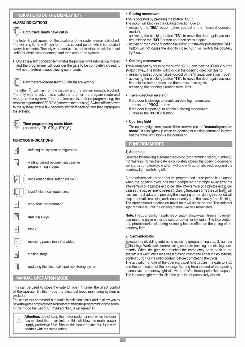
Both travel limits have cut in
The letter , will appear on the display and the system remains blocked. The warning lights will flash for a three second period which is repeated every six seconds. The only way to solve this problem is to check the travel limits for obstacles or damage and then restart the system.
• Once the alarm condition terminates the program will automatically reset and the programmer will consider the gate to be completely closed. It will not therefore accept closing commands.
Parameters loaded from EEPROM are wrong
The letter , will flash on the display and the system remains blocked. The only way to solve this situation is to enter the program mode and reprogram the system. If the problem persists after reprogramming, the problem regards the EEPROM (incorrect memorising). Switch off the power to the system, after a few seconds switch it back on and then reprogram the system.
Time programming mode block ( caused by: TB, FTC_I, FTC_S )
FUNCTION INDICATIONS
defining the system configuration
waiting period between successive programming stages
deceleration time setting (value 1)
level 1 electrical input sensor
work time programming
opening stage
block
reclosing pause (only if enabled)
closing stage
updating the electrical input monitoring system
This can be used to close the gate (or open it) under the direct control of the operator (in this mode the electrical input monitoring system is excluded.The aim of this command is to make installation easier and to allow you to have the gate completely closed before starting the programming procedure. In this mode the Led "L3" (marked "UPL") will remain lit.
Attention: do not keep the motor under tension when the door has reached the travel limit as this will blow the motor power supply protective fuse. Should this occur replace the fuse with another with the same rating.
MANUAL OPERATION MODE
FUNCTION MODES

14
Attention! Before starting the gate/gate must be moved to the completely closed position. Press the "SEL" button to move the gate to this position.
• Make sure that display "D1" is off and the LEDs "L4", "L5","L6", "L7" and "L8" are all lit .
• Open the "Standard wiring diagram" which is folded inside the last page of this manual and carry out the programming procedure.
PROGRAMMING PROCEDURE (Setting the programmer and the work times)
Dynamic button open-close
PRESSPROG
Dynamic button open-blockclose-block
Automaticreclosingenabled
Automaticreclosingexcluded
PRESS SEL
PRESSPROG
PRESS SEL
ACTIVE FUNCTION
Preflashingenabled
PRESSPROG
Preflashingexcluded
Warning lightoutputfixed
Decelerationanabled PRESS
PROG
Decelerationexcluded
D1PRESS THE PROG BUTTON FOR MORE THAN 4 SECONDS: THE PARAMETER DEFINITION LETTER "d" WILL APPEARON THE DISPLAY (STAGE "A")
1...4... sec.
1... sec.
ACTIVE FUNCTION
PRESSSEL
1...20... sec.
AFTER 1 SECOND THE DIGIT "1" WILL APPEAR (FIRST PROGRAMMING STEP). THIS NUMBER CAN BE EITHER FLASHING OR FIXED
Note 1
Note 2
PRESS SEL
PRESSPROG
Travel limitsenabled
WAIT FOR ABOUT 20 SECONDS WITHOUT PRESSING ANY BUTTONS: THE PROGRAMMER WILL SAVE THE PARAMETERS SET UP TO NOW AND WILL QUIT PROGRAMMING.
PRESSSEL
ALTERNATING
ALTERNATING
PRESSSEL
PRESSPROG
ALTERNATING
ALTERNATING
PRESSPROG
FIXEDVALUE
PRESSSEL
ALTERNATING
ALTERNATING
PRESSPROG
FIXEDVALUE
FIXEDVALUE
PRESSING THE "PROG" BUTTON WILL MOVE YOU TO STAGE "B" . PROGRAMMING THE DECELERATION TIME.THE VALUES CAN BE CHOSEN FROM 1 TO 4 SECONDS.
PRESSPROG
PRESS SEL
1...20... sec.WAIT FOR ABOUT 20 SECONDS WITHOUT PRESSING ANY BUTTONS: THE PROGRAMMER WILL SAVE THE PARAMETERS SET UP TO NOW AND WILL QUIT PROGRAMMING.
PRESS SEL
PRESSPROG
Warning lightoutput
intermittent
SELECTION1 SECOND
SELECTION 2 SECONDS
SELECTION 4 SECONDS
PRESS SEL
PRESSPROG
Travel limitsexcluded
PRESS SEL
Note 3
Note 4
Importing notes regarding the programmer settings
Note 1 Travel direction inversion only during the closing stage.
Note 2 The travel limits must always be enabled (number fixed)
Note 3 Deceleration must be excluded for fold up doors
Note 4 The , , selection must be carried out even if deceleration is excluded: It must be decided whether the electrical sensor works as a travel limit in the last 1,2 or 4 seconds of movement in the closing direction. You are advised to set a 2 second minimum ; if decel-eration has been excluded you may also select (especially if the structure of the garage door could reduce the closing time after wear and tear through time).
CONTINUE ON PAGE 15

15
PRESSSEL
ALTERNATING
ALTERNATING
ALTERNATING
ALTERNATING
PRESSSEL
ALTERNATING
ALTERNATING
PRESSSEL
WAIT FOR ABOUT 20 SECONDS WITHOUT PRESSING ANY BUTTONS: THE PROGRAMMER WILL SAVE THE PARAMETERS SET UP TO NOW AND WILL QUIT PROGRAMMING.
PRESSSEL
PRESSING THE "PROG" BUTTON WILL MOVE YOU TO STAGE "D". PROGRAMMING THE WORK TIMES.
PRESSPROG
THE START OF THE STAGE IS INDICATED BY THE LETTER "t" APPEARING FOR 2 SECONDS AFTER WHICH THE DISPLAY SWITCHES OFF
THE OPENING TIME STARTS PROGRAMMING WHICH IS CALCULATED WHILE THE GATE IS MOVING; THE ACTIVATION OF THE OPENING TRAVEL LIMIT WILL END ALL MOVEMENT.
A MARGINE OF 4 SECONDS IS AUTOMATICALLY ADDED TO THE WORK TIME AND THEN THE PAUSE TIME COUNT STARTS.
Automaticreclosingenabled
Automaticreclosingexcluded
PRESS PROG
+ 4 sec.
THE PAUSE TIME ENDS AND RECLOSING STARTS, THE CURRENT SENSOR CONTINUES CALIBRATING UNTIL THE GATE IS COMPLETELY CLOSED.
THE OPERATION WAS NOT SUCCESSFUL.YOU WILL HAVE TO REPEATPROGRAMMING CYCLE.
WHEN THE GATE ARRIVES AT THE COMPLETELY CLOSED POSITION THE PROGRAMMER SAVES THE PARAMETERS AND QUITS PROGRAMMING
PRESSING THE "PROG" BUTTON WILL MOVE YOU TO STAGE "C" SETTING THE CURRENT SENSOR. THE VALUES RANGE FROM 1 TO 3. THE DEFAULT VALUE IS 2 (THE VALUES 1 OR 3 CAN APPEAR FIXED IF THE CURRENT SENSOR HAS ALREADY BEEN PROGRAMMED
PRESSSEL
THE PROGRAMMER SAVES ALL DATA AND QUITS PROGRAMMING WITHOUT MODIFYING THE MEMORISED WORK TIMES
PRESS PROG
PRESS PROG
FIXED VALUE
PRESS PROG
FIXED VALUE
FIXED VALUE
MINIMUMTORQUE
MEDIUMTORQUE
MAXIMUMTORQUE
Important notes for work time programmingThe intervention of the travel direction inversion or blocking photocell or pressing the blocking button during time programming will stop the gate, while the flashing warning light will remain lit, indicating that the programmer is in an active phase. The figure will flash on the display. The work time count is blocked, but once the alarm situation has been resolved or the blocking button has been released (only active while it is being pressed down) the gate movement will start up again automatically. As each new movement command starts slowly the work time calculation will be false therefore you must reprogram the work times.
Warning! Pressing the "SEL" button during time programming (after having moved the gate) will impede the completion of the procedure
Warning! Program the work time so that the gate always opens completely. The end of programming is indicated by the courtesy light switching on (the activation times of which are now already programmed.
The courtesy light time equals: opening time + pause time + closing time + 30 seconds. If you select the semiautomatic function; program-ming a long pause period (max. 5 seconds) will increase the activation time of the courtesy light.
Current sensorThe programmer checks the electrical input to the motor, detecting any eventual increase in effort above the normal operating limits. To guar-antee correct operation even under various climatic and mechanical conditions, the programmer recalibrates itself each time it receives an opening command from the "completely closed" position. This allows the system to detect any increase in effort which wasn't present during programming and to compensate so that the force required to block the gate remains constant, so guaranteeing optimum operation.
Warning! During the self-calibrating stage the electrical cur-rent monitoring system will not cut in; you must therefore avoid forcing the gate during the first seconds of the opening operation.
The work time management allows the system to control the position of the gate. During blackouts the programmer will lose the position of the gate (unless one of the travel limits is active) which will be considered to be "completely closed" thus allowing the opening manoeuvre. Work time management also guarantees that the following closing manoeuvre will be complete.
Warning! For this reason it is extremely important that you use a mechanical opening direction travel limit. Never exclude the travel limits during programming (step. 4 stage A).
• After repetitive travel inversion manoeuvres, with the motor stopping then restarting slowly, you may find that the time control is false and the device does not decelerate before arriving at the travel limit. If this happens during closing the travel direction will automatically invert, but once the door reaches the completely open position the time control will be reset.
TIMED TRAVEL LIMITS
CONTINUED FROM PAGE 14

16
The motor can be remotely activated using a transmitter: only the sequential function is available "open-block-close-block" and this may be activated from any of the available channels.For this reason for each transmitter enabled you need only use one of the available channels.
S449 RADIO CONTROLSMemory module This is extractable, furnished with a non volatile EEPROM type memory and contains the transmitter codes and allows you to memorise up to 300 codes (300 channel buttons). The programmed codes are maintained in this module even in the absence of power.
Attention! Before memorising the transmitters for the first time remember to cancel the entire memory content.If the electronic card has to be replaced due to failure, the module can be extracted from it and inserted into the new card. Make sure that the module is orientated in the direction shown in fig. 9 detail A.
Signal LEDs "L2" (fig. 9): Flashing quickly: cancels a single codeFlashing slowly: memorises a single codePermanently lit: memory full.
TRANSMITTER CODE MANAGEMENTA) Memorising a channel (using the associated transmitter)B) Cancelling a channel (using the associated transmitter)C) Cancelling all codes in memory D) Memorising ulterior channels via radio (without having to open the
box in which the receiver is housed)
A) Memorising a channel (fig. 9)1. Press and hold down button "P3" MEMO: the LED "L2" will flash slowly.2. At the same time activate the transmitter which is to be memorised.3. Hold down button "P3" MEMO until LED "L2" starts to flash again.4. Release the button: The LED will continue to flash.5. Activate the transmitter again (same transmitter, same channel; if the
channel is different or it is a different transmitter the memorisation attempt will abort without success)
6. End of memorisation: The LED "L2" will remain lit for 2 seconds, indicat-ing that the transmitter has been correctly memorised.
Note: It is not possible to memorise a code which is already in memory: if you attempt this, the LED will switch off when you activate the transmitter (point 2). Only after releasing the button "P3" MEMO will you be able to continue the memorising procedure. If after activating the transmitter for the first time you wait for more than fifteen seconds without activating the transmitter a second time the memo-risation attempt will abort without success.
B) Cancelling a channel (fig. 9)1. Press and hold down button "P4" DELETE: the LED "L2" will flash quickly.2. Activate the transmitter channel which is to be cancelled.3. The LED "L2" will remain lit for 2 seconds, indicating that the transmitter
has been cancelled.
Note: If the user that you wish to cancel is not in memory, The LED will stop flashing; Only after releasing the button "P4" will you be able to continue the cancellation procedure.For both the memorisation and cancellation procedures, if the button is released before activating the transmitter the procedure will abort.
C) Cancelling all user codes from memory (fig. 9)1. Keep both buttons pressed down ("P3+P4") for more than 4 seconds2. LED "L2" will remain lit during the entire cancellation time (about 8 sec.).3. LED "L2" switches off when the cancellation procedure has terminated.
Note: When the memory is almost full the time required to search for a user code could take up to 1 second from when the command was received. If led "L2" remains alight memory is completely full. To memorise a new transmitter you will first have to cancel a code from memory.
D) Memorising ulterior channels via radio• Memorisation can be activated by radio (without opening the receiver
container) if jumper "J1" has been inserted (fig. 9).1. Make sure that the jumper "J1" has been inserted (fig. 9).2. Using a transmitter, in which at least one chan-
nel button "A, B, C or D" has already been memorised in the receiver, press the button in the transmitter as shown in the figure.
Note: all the receivers within range when the channel button is pressed (and which have at least one of the transmitter channel buttons memorised) will activate their signal buzzer "B1" (fig. 9). 3. Press one of the channel buttons on the same transmitter. The receiv-
ers which do not contain that channel code will sound a five-second long "beep" and will then disactivate. The receivers which contain the channel code will sound a one-second long "beep" and will enter the "programming mode".
4. Press the previously chosen channel buttons on the transmitter which you wish to memorise; the receiver will sound 2 "beeps" of half a second each after which the receiver will be ready to receive another code.
5. To leave the programming mode wait for "3" seconds without pressing any buttons. The receiver will sound a five-second long "beep" and will then exit the programming mode.
• When the memory is entirely occupied the buzzer will sound 10 rapid "beeps" and will automatically leave the "programming via radio" mode. Led "L2" will remain lit on the receiver. The same signal is given each time you try to enter "programming via radio" when the memory is full.
CONNECTING THE 433,92 MHz MODULE ANTENNAThe receiver is supplied with its own antenna which consists of a piece of rigid wire 170 mm in length.In alternative it is possible to connect an ANS400 tuned antenna using a coaxial cable RG58 (impedance 50Ω) with a maximum length of 15 m.
REMOTE CONTROL
MEMORIZZAZIONE CODICE TX-RX
RCQ449100
13-04-2001
DM0531 Description :
Product Code :
Date :
Drawing number :
P.J.Heath
CARDIN ELETTRONICA S.p.A - 31020 San Vendemiano (TV) Italy - via Raffaello, 36 Tel: 0438/401818 Fax: 0438/401831
Draft :
All rights reserved. Unauthorised copying or use of the information contained in this document is punishable by law
MR

17
DISTANCE MINIMALE ENTRE LE PLAFOND ET LE POINT PLUS HAUT DE LA TRAJECTOIRE
• Ce livret est destiné à des personnes titulaires d’un certificat d’aptitude pro-fessionnelle pour l’installation des "APPAREILS ÉLECTRIQUES" et requiert une bonne connaissance de la technique appliquée professionnellement. Les matériels utilisés doivent être certifiés et être adaptés aux conditions atmos-phériques du lieu d’implantation.
• Les travaux de maintenance ne doivent être effectués que par un personnel qualifié. Avant une quelconque opération de nettoyage ou de maintenance, mettre l’appareil hors tension.
• Les appareils décrits dans ce livret ne doivent être destinés qu’à l’utilisation pour laquelle ils ont été expressément conçus à savoir: "La La motorisation de portes basculantes à contrepoids". Une diverse utilisation des produits ou leur destination à un usage différent de celui prévu et/ou conseillé n’a pas été expérimentée par le Fabricant. Par conséquent, les travaux effectués sont exclusivement sous la responsabilité de l’installateur. Le Constructeur décline toute res-ponsabilité en cas d'installation électrique non conforme aux normes en vigueur, notamment en cas de circuit de protection (mise à terre) inefficace.
• Le programmateur est doté d'un dispositif de contrôle du courant absorbé par le moteur; tel dispositif a pour but de bloquer la manœuvre en cas de condition d'urgence. Ce contrôle ne s'effectue toutefois pas:- pendant les 5 premières secondes de la phase d'ouverture d'un portail
complètement fermé;- pendant les 2,5 premières secondes de tout autre mouvement.
Par conséquent, éviter de soumettre la porte à des contraintes pendant telles phases, sans quoi le fusible "F3" du moteur pourrait intervenir.
• Après avoir installé le dispositif (et avant la mise sous tension de la centrale), procéder de la façon suivante: contrôler que le mouvement du vantail, effec-tué manuellement, n'oppose pas une résistance particulièrement prononcée. Accrocher ensuite le chariot au patin d'entraînement et contrôler que le fin de course en ouverture soit activé par le chariot.
• Procéder à la mise sous tension de la centrale; si le fin de course est effectivement actionné, un trait clignotant apparaît sur l'afficheur; ce qui indique que le système se trouve en phase d'arrêt avant la refermeture automatique. Actionner en mode manuel la fermeture du vantail en appuyant sur la touche "SEL". La manœuvre dure tant que la touche est appuyée et s'interrompt dès son relâchement.
Nota: le fait d'appuyer également sur la touche "PROG" pendant la fermeture en mode manuel déclenchera, après l'arrêt d'inversion, une manœuvre d'ouverture. Pour plus de détails, voir à page 20 "Mode manuel".
Attention! Les seules sécurités qui peuvent bloquer le mouvement en mode manuel sont la touche de blocage et les fins de course. Dès fermeture complète du vantail, relâcher la touche "SEL": ne pas forcer ultérieurement la fermeture.Attention! vérifier toujours que la chaîne soit accrochée au chariot d'entraînement avant de procéder à la programmation et que le portail soit complètement fermé.
• À ce point, il est possible de procéder à la programmation du système. Pour ce faire, lire le paragraphe "Procédé de programmation" (page 21, 22).
Nota: Si un contrôle de l'état du fusible "F2" s'impose, mettre d'abord le program-mateur hors tension; ne procéder à sa remise sous tension qu'après avoir inséré le fusible. Ne jamais invalider les fins de course (voir "Procédé de programmation" nota 2 à la page 21) et contrôler que le fin de course en ouverture soit toujours branché. Le ralentissement doit être invalidé pour les portes sectionnales! (voir "Procédé de programmation" nota 3 à la page 21).
Attention! La présence du senseur de courant ne dispense pas d'ins-taller les cellules photoélectriques ou d'autres dispositifs de sécurité prévus par les normes en vigueur.
Application possibleLe groupe moteur GL112409 est indiqué pour la motorisation de portes basculantes à ressorts, portes sectionnales, portes basculantes à contrepoids débordante ou non débordante pour tablier de porte H. maxi. 3 m, L. maxi. 3,5 m et d'un poids maxi. de 70 kg. En fonction du type de porte, choisir le kit à installer (voir accessoires).
Description technique- Moteur alimenté à 24 Vdc.- Caisson du réducteur en aluminium moulé sous pression. Dans ce caisson opère
un système de réduction à vis sans fin et roue à dents hélicoïdales en matière thermoplastique, lubrification par graisse fluide.
- Contenant pour chaîne, constitué de deux coques en matière plastique en mesure de loger l'enroulement complet de la chaîne et de la garder séparée des parties électroniques.
- Programmateur électronique avec récepteur radio incorporé.- Éclairage de zone (E14 - 230 Vac - 40W).- Couvercle en matière plastique antichoc et plafonnier en plastique opalin.
Accessoires320/GL1124BKit système d'entraînement pour porte basculante à contrepoids avec guide chariot d'une longueur de 2100 mm et bras cintré adaptateur "9"-"11" (fig. 6).320/GL1124SKit système d'entraînement pour porte basculante à ressorts/porte sectionnale avec guide chariot d'une longueur de 3150 mm, levier cintré "10" (fig. 5) et deux étriers perforés "5" (fig. 3).316/GL20SBDispositif de déverrouillage à câble.
Attention! Seulement pour les clients de l'EU - Marquage WEEE.Ce symbole indique l’obligation de ne pas éliminer l’appareil, à la fin de sa durée de vie, avec les déchets municipaux non triés et de procéder à sa collecte sélective. Par conséquent, l’utilisateur doit remettre l’appareil à un centre de collecte sélective des déchets électroniques et électriques ou au revendeur qui est tenu, lorsqu’il fournit un nouvel appareil, de faire en sorte que les déchets puissent lui être remis, sur une base de un pour un, pour autant que l’appareil soit de type équivalent à celui qu’il fournit.
La collecte sélective des équipements électriques et électroniques en vue de leur valorisation, leur traitement et leur élimination dans le respect de l’environnement contribue à éviter la nocivité desdits équipements pour l’environnement et pour la santé et à encourager leur recyclage. L’élimination abusive de l’équipement de la part du détenteur final comporte l’application des sanctions administratives prévues par les normes en vigueur dans l’État Membre d’appartenance.
Important! Avant de réaliser l'installation, vérifier que les parties, aussi bien fixes que mobiles, de la structure à automatiser fonctionnent parfaitement et que celle-ci ait été construite conformément aux normes en vigueur. Dans cet objec-tif, contrôler la rigidité du tablier de la porte (si nécessaire, renforcer la structure) et le coulissement correct des guides (il est conseillé de lubrifier toutes les parties mobiles). Contrôler que la distance minimale entre le point plus haut de la trajec-toire d'ouverture de la porte et la plafond ne soit pas inférieure à 60 mm (fig. 1).
Attention! Le rail doit être monté de 10 à 20 mm au-dessus du bord supérieur de la porte. Cette position garantit un fonctionnement optimal et est indispensable pour que la porte n’aille jamais heurter contre le rail durant le fonctionnement (fig. 1 dét. A).
60 mm60 mm 60 mm
SCALA: 1:2
Prodotti Technocity
GL1024 (traino)
06-04-98
DI0059 Description :
Product Code :
Date :
Drawing number :
P.J.Heath
CARDIN ELETTRONICA S.p.A - 31020 San Vendemiano (TV) Italy - via Raffaello, 36 Tel: 0438/401818 Fax: 0438/401831
Draft :
All rights reserved. Unauthorised copying or use of the information contained in this document is punishable by law
Distanze tra il soffitto e la porta
10 - 20 mm
A
SCALA: 1:2
Prodotti Technocity
GL1024 (traino)
26-01-2000
DI0142 Description :
Product Code :
Date :
Drawing number :
P.J.Heath
CARDIN ELETTRONICA S.p.A - 31020 San Vendemiano (TV) Italy - via Raffaello, 36 Tel: 0438/401818 Fax: 0438/401831
Draft :
All rights reserved. Unauthorised copying or use of the information contained in this document is punishable by law
INSTALLAZIONE PORTA A CONTRAPPESI spazio di 10 mm
1Porte basculanteà ressorts Porte sectionnale Porte à contrepoids
CONSIGNES IMPORTANTES CONSIGNES IMPORTANTES CONSIGNES IMPORTANTES
LIRE ATTENTIVEMENT LES CONSIGNES SUIVANTES AVANT DE PROCÉDER À LA POSE. PRÊTER GRANDE ATTENTION À TOUTES LES SIGNALISATIONS QUI SE TROUVENT DANS LE TEXTE. LE NON RES-PECT DE CES CONSIGNES POURRAIT COMPROMETTRE LE BON FONCTIONNEMENT DU SYSTÈME.
CONSIGNES POUR L’UTILISATION

18
montaggio motore
GL1124
19-10-98
DM0380 Description :
Product Code :
Date :
Drawing number :
P.J.Heath
CARDIN ELETTRONICA S.p.A - 31020 San Vendemiano (TV) Italy - via Raffaello, 36 Tel: 0438/401818 Fax: 0438/401831
Draft :
All rights reserved. Unauthorised copying or use of the information contained in this document is punishable by law
GL1124
1
4
5
2
93
10
8
7
4
6
2
5
10
11
5
55
montaggio motore preliminari
GL1024
21-05-98
DM0368 Description :
Product Code :
Date :
Drawing number :
P.J.Heath
CARDIN ELETTRONICA S.p.A - 31020 San Vendemiano (TV) Italy - via Raffaello, 36 Tel: 0438/401818 Fax: 0438/401831
Draft :
All rights reserved. Unauthorised copying or use of the information contained in this document is punishable by law
GL1024
B
G2ACD
F
E
L
G12
• Le guide doit être monté perpendicu-lairement à la porte et parallèlement au plafond.
• Marquer exactement le centre de la porte et tracer, perpendiculairement à la porte, une marque sur le plafond pour faciliter le positionnement du guide.
• Fixer les équerres antérieures du guide à la traverse fixe en partie haute de la porte en utilisant des vis M6 ou des vis-tarauds 6,3 x 19 (fig. 4).
• Marquer au plafond la position des points de fixation des étriers perforés de support guide postérieurs "5" (fig. 4) et éventuellement des étriers centraux "5a" (fig. 4) en se référant à la marque tracée précédemment au plafond. Pour le perçage se servir d'un foret de 10 pour chevilles.
• Fixer les étriers perforés de support guide au plafond, perpendiculairement à celui-ci, à l'aide de vis M6.
• Serrer les vis de fixation guide antérieures.• Débloquer le chariot d'entraînement en le tirant légèrement et le faire coulisser
sur le guide de façon à le placer en avant, à proximité de la porte.
Après quoi, selon les cas:
A) Porte sectionnale, porte basculante à ressorts (fig. 5) • Fixer au moyen de 6 vis-tarauds 4,9 x 19 ou de rivets
l'équerre d'entraînement "8" sur la partie haute de la porte, au centre déterminé précédemment;
• Raccorder le levier cintré "10" à l'équerre d'en-traînement et au chariot d'entraînement "8" au moyen du pivot et des bagues d'arrêt fournis en dotation. Selon les cas, pour pouvoir utiliser au maximum la course du chariot, il faudra peut-être raccourcir ce levier (cette opération est facilitée par les trous déjà percés) et déplacer la partie initiale du guide (augmenter la cote "A" fig. 4 au moyen d'entretoise).
B) Porte basculante à contrepoids (fig. 6) • Fixer au moyen de 4+4 vis-tarauds 4,9 x 19 le bras
cintré adaptateur "9" au centre et absolument à fil de la partie haute de la porte "12". Si le point inférieur de fixation ne coïncide pas avec une traverse "13" de la structure de la porte, ajouter un renfort "14".
• Raccorder le méplat perforé "11" au chariot d'en-traînement à l'aide du pivot et des bagues d'arrêt fournis en dotation et au bras cintré adaptateur "9" au moyen de 2 vis M8 x 20 et écrous;
• S'assurer du fonctionnement correct, c'est-à-dire qu'à la course maximum du chariot doit cor-respondre une ouverture complète de la porte;
• Vérifier l'équilibrage de la porte (avec moteur débloqué, la porte doit rester immobile, parfaitement en équilibre à n'importe quel point d'ouverture).
MaintenanceContrôler régulièrement les parties mobiles (pivots, câbles) et procéder éven-tuellement à leur lubrification.
Important! Le guide en aluminium est fourni en dimensions standard (voir acces-soires). Dans l’hypothèse où une dimension inférieure s’imposerait comportant donc la coupe du guide, il est interdit de d’accoupler le côté coupé avec l'opérateur.1. Engager le curseur "A", la chaîne et les méplats de support "C" dans le loge-
ment relatif " " du guide "B".2. Placer le guide "B" en contact avec la tête de l'opérateur "D" en utilisant un
maillet "E". Éliminer les rognures (entre tête du rail et base en plastique) qui s’accumulent pendant l’insertion du rail.
Attention! Il ne doit pas y avoir de discontinuités sur le parcours de la chaîne entre l’opérateur et le guide en aluminium
3. Monter les quatre vis et rondelles "L" et les serrer à fond.4. Insérer le chariot d'entraînement "F" dans le guide "B" de façon à
l'accrocher au curseur "A", avec méplat perforé dirigé vers le côté opposé à l'opérateur "D".
5. Fixer le support du micro-interrupteur de fin de course "G" au guide "B" (voir le détail de l'accrochage). Il sera possible ensuite de le faire coulisser jusqu'au point souhaité.
Montage du guide (fig. 3)• Positionner les équerres antérieures de fixation guide "4" et les fixer aux pla-
quettes relatives (introduites dans les rainures prévues sur le guide) au moyen des vis fournies en dotation.
• Monter les étriers perforés du support de guide "5" en les positionnant sur les vis qui fixent l'actionneur "L" (fig. 2) au guide et en utilisant les plaquettes "L" prévues à cet effet et placées en position intermédiaire (environ 1/3 vers l'avant).
• Fixer le câble avec relatif pommeau de déverrouillage "E" à l'élément d'accro-chage/décrochage du chariot (fig. 3a).
• Éliminer le système de fermeture de la porte et le remplacer par le dispositif de déverrouillage à câble (voir fig. 3a).
PRÉPARATION AVANT LE MONTAGE INSTALLATION
Détail d'accrochage du support fin de course
10
7 8
SCALA: 1:2
Prodotti Technocity
GL1024 (traino)
07-04-98
DI0061 Description :
Product Code :
Date :
Drawing number :
P.J.Heath
CARDIN ELETTRONICA S.p.A - 31020 San Vendemiano (TV) Italy - via Raffaello, 36 Tel: 0438/401818 Fax: 0438/401831
Draft :
All rights reserved. Unauthorised copying or use of the information contained in this document is punishable by law
INSTALLAZIONE PORTONE SEZIONALE/BASCULANTE A MOLLA
SCALA: 1:2
Prodotti Technocity
GL1024 (traino)
07-04-98
DI0062 Description :
Product Code :
Date :
Drawing number :
P.J.Heath
CARDIN ELETTRONICA S.p.A - 31020 San Vendemiano (TV) Italy - via Raffaello, 36 Tel: 0438/401818 Fax: 0438/401831
Draft :
All rights reserved. Unauthorised copying or use of the information contained in this document is punishable by law
INSTALLAZIONE BASCULANTE A TOTALE O PARZIALE RIENTRANCE
30 mm min
9
11
12
14
13
A
SCALA: 1:2
Prodotti Technocity
GL1024 (traino)
06-04-98
DI0060 Description :
Product Code :
Date :
Drawing number :
P.J.Heath
CARDIN ELETTRONICA S.p.A - 31020 San Vendemiano (TV) Italy - via Raffaello, 36 Tel: 0438/401818 Fax: 0438/401831
Draft :
All rights reserved. Unauthorised copying or use of the information contained in this document is punishable by law
INSTALLAZIONE A SOFFITTO
5
5a
6
MANŒUVRE MANUELLE
4
3
5
Le motoréducteur est irréversible et garantit le ver-rouillage de la porte en fermeture. Pour le déverrouillage, à effectuer en cas de coupure de courant, procéder de la façon suivante: • Tirer le câble vers la porte comme indiqué en figure 7; le moteur se déverrouille et la porte peut être manœuvrée manuellement.Attention! Ne pas utiliser le câble pour déplacer la porte mais se servir toujours de sa poignée. • Pour verrouiller de nouveau le moteur, tirer le câble dans le sens opposé comme indiqué en figure 8 et ensuite fermer la porte. Le système de déverrouillage se réarme automatiquement.
7 8
100
mm
ED
A
B
C
E
PREMONTAGGIO
GL1024
06-04-98
DM0353 Description :
Product Code :
Date :
Drawing number :
P.J.Heath
CARDIN ELETTRONICA S.p.A - 31020 San Vendemiano (TV) Italy - via Raffaello, 36 Tel: 0438/401818 Fax: 0438/401831
Draft :
All rights reserved. Unauthorised copying or use of the information contained in this document is punishable by law
GL1024 SBLOCCO A CORDINO
3a
Nomenclature1 Actionneur électromécanique 24V avec programmateur2 Chariot d'entraînement3 Guide pour porte basculante à contre-
poids, long. 2100 mm4 Équerres antérieures de fixation guide
5 Étrier perforé support de guide6 Guide pour porte sectionnale, l. 3150 mm7 Levier cintré 8 Équerre d'entraînement9 Bras cintré adaptateur10 Plaquette de fixation11 Trou d’introduction des câbles
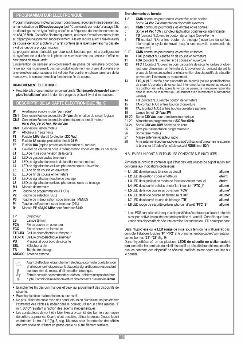
19
PROGRAMMATEUR ELECTRONIQUE
Programmateur pour moteur à courant continu avec récepteur intégré permettant la mémorisation de 300 codes usager (voir "Commande par radio" à la page 23).Le décodage est de type "rolling code" et la fréquence de fonctionnement est de 433,92 MHz. Contrôlée électroniquement, la vitesse d'entraînement est lente au départ pour augmenter successivement; elle est réduite avant l'arrivée au fin de course de façon à obtenir un arrêt contrôlé (si le ralentissement n'a pas été invalidé lors de la programmation). La programmation, réalisable par deux seuls boutons, permet la configuration du système, de la durée de la phase de ralentissement, du senseur d'effort et des temps de travail-arrêt. L'intervention du senseur anti-coincement en phase de fermeture provoque l'inversion du mouvement; ceci se produit également en phase d'ouverture si la refermeture automatique a été validée. Par contre, en phase terminale de la manœuvre, le senseur remplit la fonction de fin de course.
BRANCHEMENT ÉLECTRIQUE • Procéder à la programmation en consultant le "Schéma électrique de l'exem-
ple d'installation" plié à la dernière page du présent livret d'instructions.
B1 Avertisseur sonore mode "par radio"CN1 Connexion Faston secondaire 24 Vac alimentation du circuit logiqueCN2 Connexion Faston secondaire alimentation du circuit moteur V0: 0 Vac, V1: 22 Vac, V2: 30 VacCN3 Connexion Faston moteurD1 Afficheur à 7 segmentsF1 Fusible 1.6A retardé (protection 230 Vac) F2 Fusible 1A rapide (protection circuit 24 V) F3 Fusible 10A (rapide protection alimentation du moteur) J1 Cavalier de validation pour la mémorisation codes émetteurs par radio L1 LED de mise sous tension de la carteL2 LED de gestion codes émetteursL3 LED de signalisation mode de fonctionnement manuel L4 LED de signalisation cellules photoélectriques d'inversionL5 LED de fin de course en ouvertureL6 LED de fin de course en fermetureL7 LED de signalisation touche de blocageL8 LED de signalisation cellules photoélectriques de blocageM1 Module de mémoireP1 Touche de programmation (PROG)P2 Touche de sélection (SEL)P3 Touche de mémorisation code émetteur (MEMO) P4 Touche d'effacement code émetteur (DEL)R1 Module RF, 433,92 MHz pour émetteur S449
LP ClignoteurLS Lampe témoinFCA Fin de course en ouvertureFCC Fin de course en fermetureFTC-RX Cellule photoélectrique récepteurFTC-TX Cellule photoélectrique émetteurPS Pressostat pour bord de sécurité SEL Sélecteur à clé TB Touche de blocageANS400 Antenne externe
Avant d'effectuer le branchement électrique, contrôler que la tension et la fréquence indiquées sur la plaquette signalétique correspondent aux données du réseau d'alimentation électrique. Entre la centrale de commande et le réseau doit être interposé un inter-rupteur omnipolaire avec ouverture des contacts d'au moins 3 mm.
• Brancher les fils des commandes et ceux qui proviennent des dispositifs de sécurité.
• Brancher le câble d'alimentation au dispositif.• Ne pas utiliser de câble avec des conducteurs en aluminium; ne pas étamer
l'extrémité des câbles à insérer dans le bornier; utiliser un câble marqué "T min. 85°C" résistant à l'action des agents atmosphériques.
• Les conducteurs devront être bien fixés à proximité des borniers au moyen de colliers appropriés. Quand c’est possible, utiliser le presse-étoupe fourni en dotation. Le trou "11" (fig. 3, pag. 18) prévu pour l’introduction des câbles doit être scellé en utilisant un passe-câble ou autre élément similaire.
Branchements du bornier 1-2 CMN communs pour toutes les entrées et les sorties3 Sortie 24 Vac 7W alimentation dispositifs externes4-5 CMN communs pour toutes les entrées et les sorties6 Sortie 24 Vac 10W clignoteur (activation continue ou intermittente)7 TD (contact N.O.) entrée bouton dynamique Ouvre-Ferme8 TB (contact N.F.) entrée bouton de blocage (l'ouverture du contact
interrompt le cycle de travail jusqu'à une nouvelle commande de manœuvre)
9-17 CMN communs pour toutes les entrées et sorties10 FCC (contact N.F.) entrée fin de course en fermeture11 FCA (contact N.F.) entrée fin de course en ouverture12 FTC_I (contact N.F.) entrée pour dispositifs de sécurité (cellule photoé-
lectrique d'inversion en fermeture). L'ouverture du contact durant la phase de fermeture, suite à une intervention des dispositifs de sécurité, provoquera l'inversion du mouvement.
13 FTC_S (N.F.) entrée pour dispositifs de sécurité (cellule photoélectrique de stop). L'ouverture de ce contact interrompt la manœuvre; au retour à la condition de veille, après le temps de pause, la manœuvre reprendra dans le sens de la fermeture ( seulement avec refermeture automatique validée).
14 TC (contact N.O.) entrée bouton de fermeture15 TA (contact N.O.) entrée bouton d'ouverture16 TAL (contact N.O.) entrée bouton ouverture partielle18 Lampe témoin 24 Vac 3W19-20 Sortie 230 Vac pour transformateur torique21-22 Alimentation programmateur 230 Vac 60Hz23-24 Sortie 230 Vac 40W éclairage de zone25 Terre pour alimentation programmateur26 Sortie terre moteur 27 Masse antenne récepteur radio28 Âme antenne récepteur radio (en cas d'utilisation d'une antenne externe,
la brancher à l'aide d'un câble coaxial RG58 imp. 50Ω)
N.B.: FAIRE UN PONT SUR TOUS LES CONTACTS N.F. INUTILISÉS
Alimenter le circuit et contrôler que l'état des leds rouges de signalisation soit conforme aux indications ci-dessous:- L1 LED de mise sous tension du circuit allumé- L2 LED de gestion codes émetteurs éteint- L3 LED de signalisation mode de fonctionnement manuel éteint- L4 LED de sécurité cellules photoél. d'inversion "FTC_I" allumé - L5 LED de fin de course en ouverture "FCA" allumé*- L6 LED de fin de course en fermeture "FCC" allumé*- L7 LED de sécurité touche de blocage "TB" allumé- L8 LED rouge de sécurité cellules photoél. d'arrêt "FTC_S" allumé
* Les LEDS sont allumés lorsque le dispositif de sécurité auquel ils sont affectés n'est pas activé (ce qui dépend de la position du vantail). Contrôler que l'acti-vation des dispositifs de sécurité entraîne l'extinction du LED correspondant.
Dans l'hypothèse où le LED rouge de mise sous tension ne s'allumerait pas, contrôler l'état des fusibles "F1"-"F2" et le branchement du câble d'alimentation sur les bornes "21"-"22" (fig. 9).Dans l'hypothèse où un ou plusieurs LEDS de sécurité ne s'allumeraient pas, contrôler les contacts du relatif dispositif de sécurité branché ou contrôler que les contacts des dispositif de sécurité inutilisés soient court-circuités sur le bornier.
DESCRIPTIF DE LA CARTE ÉLECTRONIQUE (fig. 9)
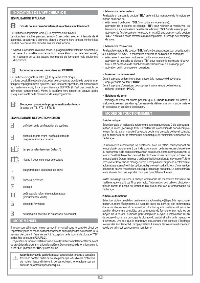
20
• Manœuvre de fermetureRéalisable en gardant le bouton "SEL" enfoncé. La manœuvre de fermeture se bloque en raison de:- relâchement du bouton "SEL" (on quitte le mode manuel);- activation de la touche de blocage "TB"; pour relancer la manœuvre de
fermeture, il est nécessaire de relâcher le bouton "SEL" et de le réappuyer;- activation du fin de course en fermeture (si installé): une pression sur le bouton
"SEL" n'entraîne pas la fermeture mais simplement l'allumage de l'éclairage de zone.
• Manœuvre d'ouvertureRéalisable en gardant le bouton "SEL" enfoncé et en appuyant tout de suite après sur le bouton "PROG". La manœuvre d'ouverture se bloque en raison de:- relâchement des deux boutons (on quitte le mode manuel);- activation de la touche de blocage "TB"; pour relancer la manœuvre d'ouver-
ture, il est nécessaire de relâcher les deux boutons et de les réappuyer;- activation du fin de course en ouverture.
• Inversion du mouvementDurant la phase de fermeture: pour passer à la manœuvre d'ouverture; - appuyer sur le bouton "PROG".Durant la phase d'ouverture: pour passer à la manœuvre de fermeture; - relâcher le bouton "PROG".
• Éclairage de zoneL'éclairage de zone est allumé pendant que le "mode manuel" est activé. Il s'allume également pendant qu'on essaie de délivrer une commande mais le fin de course en empêche l'exécution.
1) AutomatiqueSélectionnable en validant la refermeture automatique (étape 2 de la program-mation, numéro éclairage fixe). En partant de la condition de portail complè-tement fermé, la commande d'ouverture déclenche un cycle de travail complet qui se terminera par la refermeture automatique et l'extinction temporisée de l'éclairage.
La refermeture automatique se déclenche avec un retard correspondant au temps d'arrêt programmé, à partir de la conclusion de la manœuvre d'ouverture ou du moment de la dernière intervention des cellules photoélectriques durant le temps d'arrêt (l'intervention des cellules photoélectriques provoque un "reset" du temps d'arrêt). Durant le temps d'arrêt, sur l'afficheur clignote le symbole . Une pression sur la touche de blocage durant le temps d'arrêt empêche la refermeture automatique et entraîne l'interruption du clignotement sur l'afficheur. L'intervention des fins de course mécaniques provoque le blocage du vantail. La lampe témoin reste allumée tant que le portail n'est pas complètement fermé.
Nota: l'éclairage s'allume à chaque commande de manœuvre transmise au système, que ce soit par fil ou par radio; l'intervention des cellules photoélec-triques durant la phase de fermeture n'a aucun effet sur la temporisation de l'éclairage.
2) Semi-automatiqueSélectionnable en invalidant la refermeture automatique (étape 2 de la program-mation, numéro clignotant). Le cycle de travail est géré par des commandes distinctes d'ouverture et de fermeture. Une fois que le système est arrivé en position d'ouverture complète, une commande de fermeture, par radio ou au moyen de la touche, s'impose pour compléter le cycle. L'intervention du fin de course d'ouverture provoque le blocage du vantail et la fin de la manœuvre d'ouverture. Une fois que la manœuvre d'ouverture s'est conclue, l'éclairage s'éteint dès écoulement du temps préétabli. La lampe témoin reste allumée tant que le portail n'est pas complètement fermé.
INDICATIONS DE L'AFFICHEUR (D1)
SIGNALISATIONS D'ALARME
Fins de course ouverture/fermeture activés simultanément.
Sur l'afficheur apparaît la lettre , le système s'est bloqué.Le clignoteur s'active pendant environ 3 secondes avec un intervalle de 6 secondes, et continue à clignoter. Mettre le système hors tension, vérifier l'état des fins de course et le remettre ensuite sous tension.
• Quand la condition d'alarme cesse, le programmateur effectue automatique un reset. Il considère alors le vantail comme étant "complètement fermé", et n'accepte de ce fait aucune commande de fermeture mais seulement d'ouverture.
Paramètres erronés mémorisés sur EEPROM
Sur l'afficheur clignote la lettre , le système s'est bloqué.L'unique possibilité est celle d'accéder de nouveau au procédé de programma-tion pour reprogrammer le système. Si en répétant l'opération, cet inconvénient se manifeste encore, il y a un problème sur EEPROM (il n'est pas possible de mémoriser correctement). Mettre le système hors tension et essayer après quelques instants de le rallumer et de le reprogrammer.
Blocage en procédé de programmation des temps (à cause de: TB, FTC_I, FTC_S)
SIGNALISATIONS DE FONCTIONNEMENT
définition de la configuration du système
phase d'attente avant l'accès à l'étape de
programmation successive
temps de ralentissement (valeur 1)
niveau 1 pour le senseur de courant
programmation des temps de travail phase d'ouverture
blocage
arrêt avant la refermeture automatique (uniquement si validé)
phase de fermeture
actualisation des valeurs du senseur de courant
Il trouve son utilité pour fermer ou ouvrir le vantail sous le contrôle direct de l'opérateur (dans ce mode de fonctionnement, ni les dispositifs de sécurité, ni le senseur de courant n'interviennent à l'exception de la touche de blocage "TB" et des fins de course FCA/FCC).L'objectif est de faciliter l'installation et d'avoir le vantail complètement fermé avant de procéder à la programmation du système. Dans ce mode de fonctionnement, le led "L3" (marqué de "UPL") reste allumé.
Attention: éviter de garder le moteur sous tension lorsque le vantail se trouve en contact du fin de course parce que le fusible de protection du moteur risque d'intervenir. Le cas échéant, le remplacer par un autre de caractéristiques identiques.
MODE MANUEL
MODES DE FONCTIONNEMENT

21
PROCÉDÉ DE PROGRAMMATION (configurations du programmateur et du temps de travail)
Attention! Avant de commencer, le portail doit être complètement fermé. Donc, appuyer sur la touche "SEL" pour le fermer.
• Contrôler si l'afficheur à Leds "D1" est éteint et si les Leds "L4", "L5", "L6", "L7" et "L8" sont toutes allumées.
• Procéder à la programmation en consultant le "Schéma électrique de l'exemple d'installation" plié à la dernière page du présent livret d'instructions.
Touche dynam. ouvre-ferme
APPUYER SUR PROG
Tasto dinamico ouvre-arrêt ferme-arrêt
Refertmetureautomatique
validée
Refertmetureautomatique
invalidée
APPUYER SUR SEL
APPUYER SUR PROG
APPUYER SUR SEL
FONCTIONACTIVÉE
Préannonce validée APPUYER
SUR PROG Préannonce
invalidée
Sortie clignotant
fixe
Ralentissementvalidée APPUYER
SUR PROG
Ralentissementinvalidée
D1 1...4... sec.
1... sec.
FONCTIONACTIVÉE
APPUYER SUR SEL
1...20... sec.
APRÈS UNE SECONDE APPARAÎT LE CHIFFRE "1" (PREMIÈRE ÉTAPE DE LA PROGRAMMATION). IL PEUT ÊTRE SOIT FIXE SOIT CLIGNOTANT.
Nota 1
APPUYER SUR SEL
APPUYER SUR PROG
Fins de coursevalidée
LAISSER PASSER ENVIRON 20 SECONDES SANS APPUYER SUR UNE TOUCHE: LE PROGRAMMATEUR SAUVEGARDE LES PARAMÈTRES PROGRAMMÉS JUSQU'À PRÈSENT ET QUITTE LA PROGRAMMATION.
APPUYER SUR SEL
ALTERNÉS
ALTERNÉS
APPUYER SUR SEL
APPUYER SUR PROG
ALTERNÉS
ALTERNÉS
APPUYER SUR PROG
VALEUR FIXE
APPUYER SUR SEL
ALTERNÉS
ALTERNÉS
APPUYER SUR PROG
VALEUR FIXE
VALEUR FIXE
UNE PRESSION SUR LA TOUCHE "PROG" PORTE À LA PHASE "B" DE PROGRAMMATION DU TEMPS DE RALENTISSEMENT. LES VALEURS SÉLECTIONNABLES VONT DE 1 À 4 SEC.
APPUYER SUR PROG
APPUYER SUR SEL
1...20... sec.LAISSER PASSER ENVIRON 20 SECONDES SANS APPUYER SUR UNE TOUCHE: LE PROGRAMMATEUR SAUVEGARDE LES PARAMÈTRES PROGRAMMÉS JUSQU'À PRÈSENT ET QUITTE LA PROGRAMMATION.
APPUYER SUR SEL
APPUYER SUR PROG
Sortie clignotant
intermittent
SÉLECTION 1 SECONDES
SÉLECTION 2 SECONDES
SÉLECTION 4 SECONDES
APPUYER SUR LA TOUCHE PROG PENDANTPLUS DE 4 SECONDES; LA LETTRE "d"INDIQUANT LA DÉFINITION DES PARAMÈTRESDU SYSTÈME (PHASE "A") S’AFFICHE.
APPUYER SUR SEL
APPUYER SUR PROG Nota 2
Fins de courseinvalidée
APPUYER SUR SEL
Nota 3
Nota 4
Notes importantes concernant la configuration du programmateur
Note 1 L'inversion du mouvement ne se produit qu'en phase de fermeture.
Note 2 Les fins de course doivent toujours être validés (numéro éclairage fixe).
Note 3 Le ralentissement doit être invalidé pour les portes sectionnales.
Note 4 La sélection de , , s'impose même si le ralentissement a été invalidé. En effet, il est nécessaire d'établir si le senseur de courant doit agir comme fin de course dans les 1, 2 ou 4 dernières secondes de la phase de fermeture. Il est conseillé de sélectionner un temps minimum de 2 secondes ; si le ralentissement a été invalidé, opter même pour surtout si la structure du portail est telle à provoquer au fil des années une diminution du temps de fermeture.
SUITE À PAGE 22

22
APPUYER SUR SEL
ALTERNÉS
ALTERNÉS
APPUYER SUR PROG
ALTERNÉS
ALTERNÉS
APPUYER SUR PROG
VALEURFIX
APPUYER SUR SEL
ALTERNÉS
ALTERNÉS
APPUYER SUR PROG
VALEURFIX
APPUYER SUR SEL
VALEURFIX
LAISSER PASSER ENVIRON 20 SECONDES SANS APPUYER SUR UNE TOUCHE: LE PROGRAMMATEUR SAUVEGARDE LES PARAMÈTRES PROGRAMMÉS JUSQU’À CE POINT, ET QUITTE LA PROGRAMMATION.
APPUYER SUR SEL
UNE PRESSION SUR LA TOUCHE "PROG" PORTE À LA PHASE "D"LA PROGRAMMATION DU TEMPS DE TRAVAIL.
APPUYER SUR PROG
LE LANCEMENT DE CETTE PHASE EST INDIQUÉ PAR LA VISUALISATION DE LA LETTRE "t" PENDENT ENVIRON 2 SECONDES; AVENT QUE L'AFFICHEUR S'ÉTEIGNE.
LA PROGRAMMATION DU TEMPS D'OUVERTURE COMMENCE. CE TEMPS EST ÉSTABLI AVEC PORTAIL EN MOUVEMENT; L'ACTIVATION DU FIN DE COURSE EN OUVERTURE DÉTERMINE LA FIN DU MOUVEMENT.
AU TEMPS DE TRAVAIL S'AJOUTE AUTOMATIQUEMENT UNE MARGE DE 4 SECONDES, ET LE COMPTAGE DU TEMPS D'ARRÊT SE DÉCLENCHE.
Refermetureautomatique
validée
APPUYER SUR PROG
+ 4 sec.
LE TEMPS D'ARRÊT PREND FIN, LA FERMETURE SE DÉCLENCHE ET LE SENSEUR DE COURANT CONTINUE SON RÉGLAGE JUSQU'À CE LE PORTAIL ARRIVE EN POSITION DE FERMETURE COMPLÈTE.
L'OPERATION N'A PAS RÉUSSI. IL FAUDRA REFAIRE LA PROGRAMMATION.
QUAND LE PORTAIL ARRIVE EN POSITION DE FERMETURE COMPLÈTE, LE PROGRAMMATEUR SAUVEGARDE LES PARAMÈTRES, ET QUITTE LA PROGRAMMATION.
UNE PRESSION SUR LA TOUCHE "PROG" PORTE À LA PHASE "C" DE CONFIGURATION DU SENSEUR DE COURANT. LES VALEURS SÉLECTIONNABLES VONT DE 1 À 3. LA VALEUR DE DEFAULT EST 2 (LES VALEURS 1 OU 3 PEUVENT ÊTRE ALLUMÉES FIXES SI LA SENSEUR A DÉJÀ ÉTÉ PROGRAMMÉ.
APPUYER SUR SEL
LE PROGRAMMATEUR SAUVEGARDE LES DONNÉES ET QUITTE LA PROGRAMMATION SANS MODIFIER LES TEMPS MÉMORISÉS.
COUPLEMINIMUM
COUPLEMOYEN
COUPLEMAXIMUM
Refermetureautomatique
invalidée
Notes importantes concernant la programmation des temps de travailL'intervention des cellules photoélectriques d'inversion/blocage ou une pres-sion sur la touche de blocage durant la programmation des temps provoque l'interruption du mouvement; le clignoteur reste en fonction pour signaler que le programmateur est activé.Sur l'afficheur apparaît alors l'indication clignotante. Dès que la situation d'alarme cesse ou en relâchant la touche de blocage (activée seulement tant qu'elle est appuyée), le mouvement reprend automatiquement; dans cette situation le calcul du temps de travail sera inexact. Par conséquent, il faudra recommencer la programmation.
Attention ! Le fait d'appuyer sur la touche "SEL" en phase de pro-grammation des temps (après avoir fait bouger le ventail) entraîne un déroulement incorrect du procédé de programmation.
Attention! Programmer les temps de travail de façon à obtenir toujours une ouverture complète du vantail. La fin de la program-mation est signalée par l'allumage de l'éclairage de zone (dont le temps d'activation s'avère, à ce point, être programmé).
Temps de l'éclairage de zone = au temps d'ouverture + temps d'arrêt + temps de fermeture + 30 secondes. En sélectionnant le mode de fonctionnement semi-automatique avec un temps d'arrêt long (maxi. 5 min.), il est possible de prolonger le temps d'activation de l'éclairage de zone.
Senseur de courantLe programmateur effectue le contrôle de l'absorption du moteur en relevant l'augmentation des contraintes au-delà des seuils consentis pour un fonc-tionnement normal.Pour garantir un fonctionnement correct même en conditions atmosphériques et mécaniques variables, le programmateur procède à un autoréglage chaque fois qu'il intercepte une commande d'ouverture en condition de fermeture complète. Ceci permet au système de relever d'éventuelles résistances plus hautes au mouvement, inexistantes au moment de la programmation, et de les compenser de façon telle que l'effort nécessaire à arrêter le portail n'en soit pas réduit, garantissant ainsi un fonctionnement optimal.
Attention: durant la phase d'autoréglage, le senseur de courant n'intervient pas; éviter par conséquent de forcer le portail les premières secondes de la manœuvre d'ouverture.
La gestion des temps de travail permet de contrôler la position du portail.En cas de coupure de courant, le programmateur, à moins que l'un des fins de course ne s'avère être activé, perd la mémorisation de la position occupée par le portail; ce dernier est alors considéré comme étant "complètement fermé", de façon à permettre la manœuvre d'ouverture. La gestion des temps de travail garantit successivement une manœuvre de fermeture complète.
Attention! C'est pour cette raison qu'il est fondamental d'utiliser le fin de course mécanique en ouverture et de ne jamais invalider en phase de programmation les fins de course (étape 4 de la phase A).
• Plusieurs manœuvres d'inversion effectuées l'une après l'autre, entraînant donc l'arrêt du mouvement et un démarrage lent, pourraient avoir comme conséquence une altération du contrôle des temps et un manque de ralentis-sement avant l'arrivée au fin de course. Si ce case se présente en phase de fermeture, en obtiendra une inversion de mouvement mais, après l'ouverture complète, les temps de travail se rétabliront automatiquement.
FIN DE COURSE TEMPORISÉ
SUITE DE LA PAGE 21
23
COMMANDE PAR RADIO D) Mémorisation par radio d'autres canaux • La mémorisation peut être activée également par radio (sans devoir ouvrir le
boîtier contenant la centrale), si le cavalier "J1" (fig. 9) a été inséré.
1. Vérifier si le cavalier "J1" a été inséré (fig. 9).2. Utiliser une télécommande dont au moins
une des touches de canal A-B-C-D a déjà été mémorisée dans le récepteur et activer la touche à l'intérieur de la télécommande comme indiqué en figure.
Nota: tous les récepteurs qui se trouvent dans le rayon d'action de la télécom-mande et qui ont au moins un canal de l'émetteur de mémorisé, enclencheront simultanément l'avertisseur sonore "B1" (fig. 9).
3. Pour sélectionner le récepteur dans lequel il faut mémoriser le nouveau code, activer une des touches de canal de ce même émetteur. Les récepteurs qui ne contiennent pas le code de cette touche se désactiveront; ce qui est signalé par un bip de 5 secondes. Par contre, le récepteur contenant le code émettra un bip différent qui dure 1 seconde, signalant l'accès effectif au procédé de mémorisation "par radio".
4. Appuyer sur la touche de canal choisie précédemment sur l'émetteur à mémoriser. Le récepteur signalera que la mémorisation a eu lieu en émettant 2 bips d'une demi-seconde. Après quoi, le récepteur sera prêt à mémoriser un autre code.
5. Pour quitter le procédé de mémorisation, laisser passer "3" secondes sans mémoriser de codes. L'avertisseur sonore émettra un bip de 5 secondes et sortira du procédé.
• Lorsque la mémoire arrive à saturation, l'avertisseur sonore émettra 10 bips très courts et on sort automatiquement du procédé de mémorisation "par radio"; le LED "L2" reste allumé.
Cette signalisation s'obtient également à chaque tentative d'accéder au procédé de mémorisation "par radio" avec mémoire saturée.
BRANCHEMENT DE L'ANTENNE POUR MODULE RF 433,92 MHzLe récepteur est équipé d'une propre antenne qui consiste en un morceau de fil rigide d'une longueur de 170 mm.En alternative, il est possible de brancher l'antenne accordée ANS400 au moyen d'un câble coaxial RG58 (impédance 50Ω) d'une longueur max. de 15 m.
Il est possible d'actionner à distance le moteur par le biais de la télécommande. Une seule fonction est disponible (commande séquentielle "ouvre-bloque-ferme-bloque"); celle-ci peut être activée indifféremment par n'importe quel canal à disposition. Pour cette raison, pour chaque émetteur validé pour la commande, mémoriser un seul des canaux à disposition.
TÉLÉCOMMANDE RADIO SÉRIE S449Module de mémoireExtractible et doté de mémoire non volatile du type EEPROM, il contient les codes des émetteurs et permet la mémorisation de 300 codes (300 touches de canal). Dans ce module, les codes restent mémorisés même en cas de coupure de courant.
Attention! Avant de procéder à la première mémorisation, se rap-peler d'effacer entièrement la mémoire. S'il faut remplacer la carte électronique à cause d'un défaut de fonctionnement, il est possible d'extraire le module et de l'insérer dans une nouvelle carte. Son inser-tion doit obligatoirement se faire dans le sens indiqué en fig. 9 dét.A.
Signalisations LED "L2" (fig. 9)clignotement rapide: effacement d'un codeclignotement lent: mémorisation d'un codetoujours allumé: mémoire saturée.
GESTION DES CODES DES ÉMETTEURSA) Mémorisation d'un canal (au moyen du émetteur associé)B) Effacement d'un canal (au moyen du émetteur associé)C) Effacement total de la mémoire codesD) Mémorisation par radio d'autres canaux (sans devoir ouvrir le boîtier
contenant la centrale).
A) Mémorisation d'un canal (fig. 9)1. Appuyer sur le bouton "P3" MEMO et le garder enfoncé; le LED "L2" se met
à clignoter lentement.2. Activer simultanément l'émetteur sur le canal à mémoriser.3. Garder le bouton "P3" MEMO enfoncé jusqu'au moment où le LED "L2" se
remet à clignoter.4. Relâcher le bouton MEMO; le LED continue à clignoter.5. Activer une deuxième fois l'émetteur (même émetteur, même canal; si le canal
est différent ou s'il s'agit d'un autre émetteur, la mémorisation échoue).6. Conclusion de la mémorisation; le LED "L2" reste allumé pendant 2 secondes,
signalant ainsi la réussite de la mémorisation.
Nota: Il n'est pas possible de mémoriser un code déjà mis en mémoire. Si ce cas se présente, le clignotement du LED s'interrompt durant l'activation de la télécommande radio (2ème point). Ce n'est qu'après relâchement du bouton "P3" MEMO qu'il sera possible de reprendre la mémorisation.Si dans les 15 secondes qui suivent la première activation de la télécommande radio, on ne l'active pas une deuxième fois, on quitte automatiquement le procédé de mémorisation sans que le nouveau code usager ait été mémorisé.
B) Effacement d'un canal (fig. 9)1. Appuyer sur le bouton "P4" DEL et le garder enfoncé; le LED "L2" se met à
clignoter rapidement.2. Activer l'émetteur sur le canal à effacer.3. Le LED reste allumé pendant 2 sec., signalant ainsi que l'effacement a eu lieu.
Nota: si l'usager que l'on désire effacer n'est pas mémorisé, le LED s'arrête de clignoter; il sera possible de reprendre l'effacement seulement après relâchement du bouton "P4". En relâchant le bouton avant l'activation de la télécommande radio, on quitte immédiatement le procédé, qu'il soit de mémorisation ou d'ef-facement.
C) Effacement total de la mémoire usagers (fig. 9)1. Appuyer simultanément sur les deux boutons ("P3 + P4") et les garder enfoncés
pour plus de 4 secondes.2. Le LED "L2" reste allumé pendant toute la durée de l'effacement (environ 8 sec.).3. L'extinction du LED "L2" signale la conclusion de l'effacement.
Note: lorsque la mémoire du récepteur est presque saturée, la recherche de l'usager peut durer au maximum 1 seconde à compter de la réception de la commande radio. Si le led "L2" reste toujours allumé, la mémoire est saturée. Pour pouvoir mémoriser un nouveau émetteur, l'annulation d'un code de la mémoire s'impose.
MEMORIZZAZIONE CODICE TX-RX
RCQ449100
13-04-2001
DM0531 Description :
Product Code :
Date :
Drawing number :
P.J.Heath
CARDIN ELETTRONICA S.p.A - 31020 San Vendemiano (TV) Italy - via Raffaello, 36 Tel: 0438/401818 Fax: 0438/401831
Draft :
All rights reserved. Unauthorised copying or use of the information contained in this document is punishable by law
MR

24
60 mm60 mm 60 mm
SCALA: 1:2
Prodotti Technocity
GL1024 (traino)
06-04-98
DI0059 Description :
Product Code :
Date :
Drawing number :
P.J.Heath
CARDIN ELETTRONICA S.p.A - 31020 San Vendemiano (TV) Italy - via Raffaello, 36 Tel: 0438/401818 Fax: 0438/401831
Draft :
All rights reserved. Unauthorised copying or use of the information contained in this document is punishable by law
Distanze tra il soffitto e la porta
• Das vorliegende Handbuch wendet sich an Personen, die zur Installation von "ELEKTROGERÄTEN" befähigt sind und setzt gute technische Kenntnisse und die Kenntnis der geltenden Vorschriften voraus. Die verwendeten Materialien müssen zertifiziert sein und für die Umweltbedingungen der Installation geeignet sein.
• Die Wartungsarbeiten müssen von qualifiziertem Fachpersonal ausgeführt werden. Bevor irgendwelche Säuberungs- oder Wartungsarbeiten ausgeführt werden, ist die Apparatur vom Stromnetz zu trennen.
• Die hier beschriebenen Geräte dürfen nur für die Verwendung eingesetzt werden, für die sie ausdrücklich konzipiert wurden, d.h. "Garagentorantrieb für Sektional- und Kipptore". Die Anwendung und Nutzung der Produkte zu einem anderen Zweck, als es vorgesehen und/oder geraten wurde, ist nicht vom Hersteller erprobt worden. Die Installationsarbeiten erfolgen daher unter der vollständigen Verantwortung des Installateurs. Der Hersteller lehnt jegliche Verantwortung ab, wenn die elektrische Anlage nicht den geltenden Richtlinien entspricht und insbesondere wenn der Schutzkreislauf (Erdung) nicht leistungsfähig ist.
• Die Steuerungseinheit ist mit einem Kontrollelement für den vom Motor aufgenommen Strom ausgerüstet, der die Bewegung des Tors im Notfall stoppt; diese Kontrolle erfolgt jedoch nicht:- in den ersten 5 s der Öffnungsphase nach der "vollständigen Schliessung";- in den ersten 2,5 s jeglicher Bewegung.
Während dieser Phasen ist jeglicher Widerstand auf das Tor zu vermeiden, da sonst die Schmelzsicherung "F3" des Motoren-schaltkreises durchbrennt.
• Nach erfolgter Installation der Vorrichtung (und bevor die Steuereinheit mit Strom versorgt wird) ist wie folgt zu verfahren: überprüfen, dass das Tor im manuellen Betrieb keine besonderen Widerstandspunkte aufweist, danach ist der Laufwagen in den Zugschlitten einzuhaken, wobei zu überprüfen ist, dass der Endanschlag der Öffnung von dem Laufwagen ausgelöst wird.
• Die Steuereinheit mit Strom versorgen: sobald der Endanschlag aktiviert wurde, erscheint auf dem Display ein blinkender Strich, der anzeigt, dass sich das System in der Pausenphase für die automatische Wiederschliessung befindet. Das Tor im manuellen Betrieb schliessen, indem man die Taste "SEL" drückt. Die Bewegung dauert solange die Taste gedrückt gehalten wird und stoppt bei Loslassen.
Hinweis: wenn während der Schliessung im manuellen Betrieb gleichzeitig die Taste "PROG" betätigt wird, geht das Tor nach der Pause für die Bewegungsumkehr wieder auf. Für weitere Erläuterungen siehe Seite 27, "Modalität Manueller Betrieb".
Achtung! Die einzigen Sicherheitsvorrichtungen für ein Anhalten des Tors im manuellen Betrieb sind die Stopptaste und die Endanschlagsschalter. Sobald das Tor vollständig geschlossen ist, die Taste "SEL" loslassen: Danach den Verschluss nicht mehr drücken.
Achtung! Immer überprüfen, dass die Kette in den Zuglaufwagen ein-gehakt ist und dass das Tor vollständig geschlossen ist, bevor mit der Programmierung angefangen wird.
• Nun ist das Gerät für die Programmierung des Systems bereit, wie in Paragraph "Programmierverfahrung" (Seite 28, 29) beschrieben.
Hinweis: Sollte der Zustand der Sicherung "F2" festgestellt werden, muss zunächst die Stromzufuhr der Steuerungseinheit unterbrochen werden; sie darf erst dann wie-deraufgenommen werden, wenn die Sicherung eingesetzt wurde. Die Endanschlags-schalter niemals ausschliessen (siehe "Programmierung": Anmerkung 2, Seite 28) und überprüfen, dass der Endanschlagsschalter der Öffnung immer angeschlossen ist. Bei Sektionaltoren darf es zu keiner Verlangsamung in der Bewegung kommen! (siehe "Programmierung": Anmerkung 3, Seite 28).
Achtung! Das Vorhandensein des Stromsensors enthebt nicht von der Pflicht, die Lichtschranken oder andere von den geltenden Richtlinien vorgesehene Sicherheitsvorrichtungen zu installieren.
AnwendungsmöglichkeitenDie Motoreinheit GL112409 bewegt Kipptoren mit Federzug, Sektionaltore und Kipp-toren mit vollständigem oder teilweisem Rücktritt, mit Tormassen von h max.= 3 m, L max.= 3,5 m und einem Höchstgewicht von 70 kg.Benötigten Bausatz (siehe Zubehör) je nach Art des Tors auswählen.
Technische Beschreibung- Motor mit 24 Vdc-Versorgung.- Getriebegehäuse aus Aluminiumpressguss. Im Inneren arbeitet ein Untersetzungs-
getriebe mit Schnecke und Schrägzahnrad aus thermoplastischem Material mit Flüssigfett-Schmierung.
- Kettengehäuse bestehend aus zwei Kunststoffkästen, die den Aufwicklungsverlauf der Kette umhüllen und von den elektronischen Teilen getrennt halten.
- Elektronische Steuerung mit eingebautem Funkempfänger- Wachlicht (E14 - 230 Vac - 40 W)- Abdeckung aus schlagfestem Kunststoff und Deckenlampe aus opalem Kunst-
stoff.
Zubehör320/GL1124B:Bausatz für Zugvorrichtung für Kipptoren mit Gegengewichten mit Zugwagenführung, Länge 2100 mm, und gebogenem Adapterarm "9"-"11" (Abb. 6).320/GL1124S:Bausatz für Zugvorrichtung für Kipptoren mit Federzug bzw. Kipptoren mit Zugwa-genführung, Länge 3150 mm, gebogenem Hebel "10" (Abb. 5) und zwei Lochband-schienen "5" (Abb. 3).316/GL20SB:Seilzugentriegelung.
Achtung! Nur für EG-Kunden – WEEE-Kennzeichnung.Das Symbol zeigt an, dass das Produkt am Ende seines Lebens-zyklus getrennt von anderen Abfällen gesammelt werden muss. Der Benutzer muss daher das Gerät in geeignete Zentren für die getrennte Sammlung von Elektronik- und Elektroschrott bringen oder zum Zeitpunkt des Erwerbs eines neuen Geräts gleicher Art im Verhältnis eins zu eins beim Händler abgeben.
Die geeignete getrennte Sammlung für die Zuführung zum Recycling, zur Aufbereitung und zur umweltfreundlichen Entsorgung trägt dazu bei, mögliche negative Auswirkungen auf die Umwelt und die Gesundheit zu vermeiden und fördert das Recycling der Materialien.Die widerrechtliche Entsorgung des Produkts durch den Besitzer führt zur Anwendung der von den geltenden Vorschriften im Mitgliedstaat der Euro-päischen Gemeinschaft vorgesehenen Verwaltungsstrafen.
Wichtig! Vor der Installation ist zu überprüfen, dass die zu automatisierende Einrich-tung in ihren festen und beweglichen Teilen einwandfrei funktioniert und entsprechend den geltenden Richtlinien ausgeführt wurde. Anschließend ist die ausreichende Robustheit des Torrahmens (falls notwendig die Struktur verstärken) und der gute Verlauf der Führungen sicherzustellen (es ist jedoch ratsam, alle beweglichen Teile zu schmieren). Überprüfen, dass der Mindestabstand zwischen dem höchsten Punkt des Öffnungsverlaufs des Tors und der Decke nicht geringer als 60 mm (Abb. 1) ist.
Achtung! Die Führung muss zwischen 10 und 20 mm oberhalb der oberen Türkante montiert werden; diese Position garantiert einen optimalen Betrieb und ist unerlässlich, damit die Tür während des normalen Betriebs niemals gegen die Führung schlägt (Abb. 1 Det. A).
MINDESTABSTAND ZWISCHEN DECKE UND DEM HÖCHSTEN PUNKT DES TORVERLAUFS
Kipptor mit Federzug SektionaltorKipptor mitGegengewichten
10 - 20 mm
A
SCALA: 1:2
Prodotti Technocity
GL1024 (traino)
26-01-2000
DI0142 Description :
Product Code :
Date :
Drawing number :
P.J.Heath
CARDIN ELETTRONICA S.p.A - 31020 San Vendemiano (TV) Italy - via Raffaello, 36 Tel: 0438/401818 Fax: 0438/401831
Draft :
All rights reserved. Unauthorised copying or use of the information contained in this document is punishable by law
INSTALLAZIONE PORTA A CONTRAPPESI spazio di 10 mm
1
WICHTIGE HINWEISE WICHTIGE HINWEISE WICHTIGE HINWEISE VOR DER INSTALLATION SOLLTEN DIE NACHSTEHENDEN HINWEISE AUFMERKSAM GELESEN WERDEN. BESONDERE AUFMERKSAMKEIT SOLLTE ALLEN IM TEXT BEFINDLICHEN HINWEISEN
GESCHENKT WERDEN. DEREN NICHTBEACHTUNG KÖNNTE DEN ORDENTLICHEN BETRIEB DES SYSTEMS BEEINTRÄCHTIGEN.
BENUTZERHINWEISE
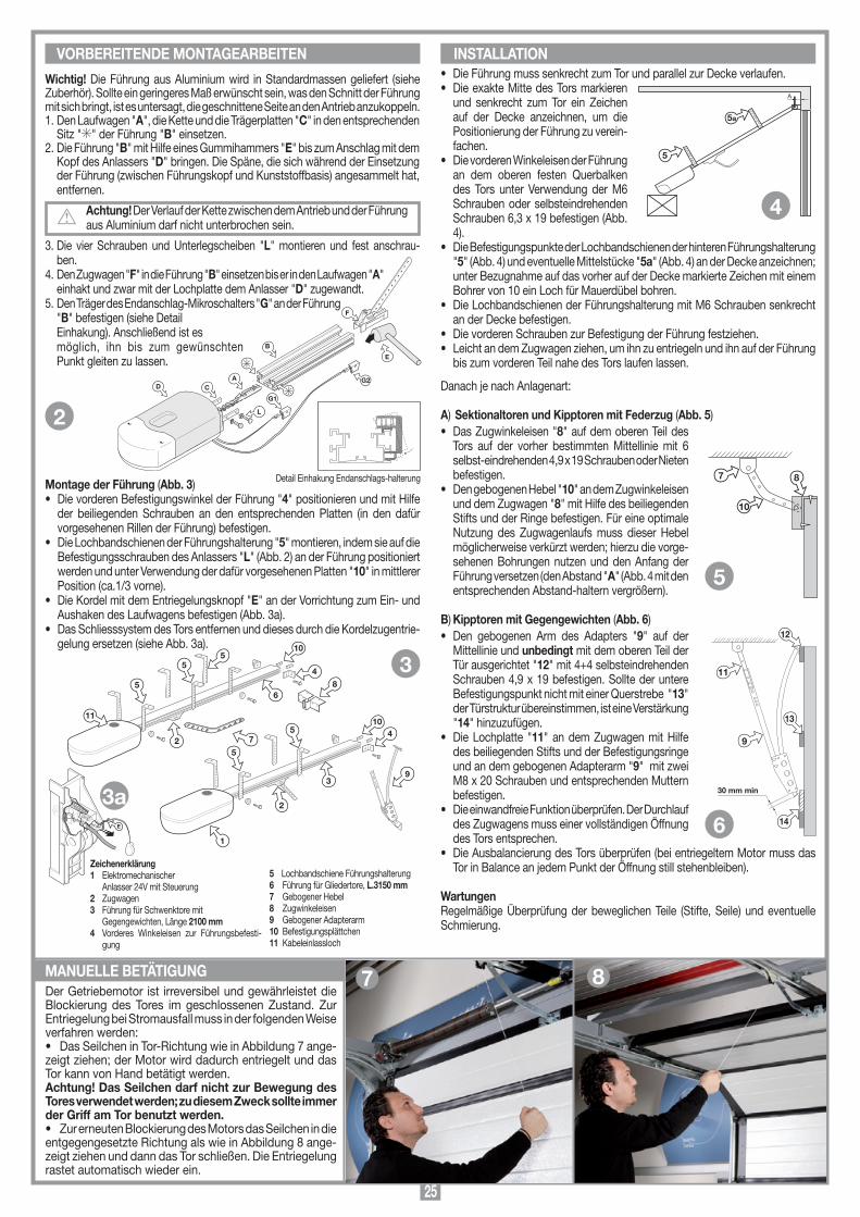
25
10
7 8
SCALA: 1:2
Prodotti Technocity
GL1024 (traino)
07-04-98
DI0061 Description :
Product Code :
Date :
Drawing number :
P.J.Heath
CARDIN ELETTRONICA S.p.A - 31020 San Vendemiano (TV) Italy - via Raffaello, 36 Tel: 0438/401818 Fax: 0438/401831
Draft :
All rights reserved. Unauthorised copying or use of the information contained in this document is punishable by law
INSTALLAZIONE PORTONE SEZIONALE/BASCULANTE A MOLLA
A
SCALA: 1:2
Prodotti Technocity
GL1024 (traino)
06-04-98
DI0060 Description :
Product Code :
Date :
Drawing number :
P.J.Heath
CARDIN ELETTRONICA S.p.A - 31020 San Vendemiano (TV) Italy - via Raffaello, 36 Tel: 0438/401818 Fax: 0438/401831
Draft :
All rights reserved. Unauthorised copying or use of the information contained in this document is punishable by law
INSTALLAZIONE A SOFFITTO
5
5a
montaggio motore
GL1124
19-10-98
DM0380 Description :
Product Code :
Date :
Drawing number :
P.J.Heath
CARDIN ELETTRONICA S.p.A - 31020 San Vendemiano (TV) Italy - via Raffaello, 36 Tel: 0438/401818 Fax: 0438/401831
Draft :
All rights reserved. Unauthorised copying or use of the information contained in this document is punishable by law
GL1124
1
4
5
2
93
10
8
7
4
6
2
5
10
11
5
55
100
mm
ED
A
B
C
E
PREMONTAGGIO
GL1024
06-04-98
DM0353 Description :
Product Code :
Date :
Drawing number :
P.J.Heath
CARDIN ELETTRONICA S.p.A - 31020 San Vendemiano (TV) Italy - via Raffaello, 36 Tel: 0438/401818 Fax: 0438/401831
Draft :
All rights reserved. Unauthorised copying or use of the information contained in this document is punishable by law
GL1024 SBLOCCO A CORDINO
montaggio motore preliminari
GL1024
21-05-98
DM0368 Description :
Product Code :
Date :
Drawing number :
P.J.Heath
CARDIN ELETTRONICA S.p.A - 31020 San Vendemiano (TV) Italy - via Raffaello, 36 Tel: 0438/401818 Fax: 0438/401831
Draft :
All rights reserved. Unauthorised copying or use of the information contained in this document is punishable by law
GL1024
B
G2ACD
F
E
L
G1
• Die Führung muss senkrecht zum Tor und parallel zur Decke verlaufen.• Die exakte Mitte des Tors markieren
und senkrecht zum Tor ein Zeichen auf der Decke anzeichnen, um die Positionierung der Führung zu verein-fachen.
• Die vorderen Winkeleisen der Führung an dem oberen festen Querbalken des Tors unter Verwendung der M6 Schrauben oder selbsteindrehenden Schrauben 6,3 x 19 befestigen (Abb. 4).
• Die Befestigungspunkte der Lochbandschienen der hinteren Führungshalterung "5" (Abb. 4) und eventuelle Mittelstücke "5a" (Abb. 4) an der Decke anzeichnen; unter Bezugnahme auf das vorher auf der Decke markierte Zeichen mit einem Bohrer von 10 ein Loch für Mauerdübel bohren.
• Die Lochbandschienen der Führungshalterung mit M6 Schrauben senkrecht an der Decke befestigen.
• Die vorderen Schrauben zur Befestigung der Führung festziehen.• Leicht an dem Zugwagen ziehen, um ihn zu entriegeln und ihn auf der Führung
bis zum vorderen Teil nahe des Tors laufen lassen.
Danach je nach Anlagenart:
A) Sektionaltoren und Kipptoren mit Federzug (Abb. 5)• Das Zugwinkeleisen "8" auf dem oberen Teil des
Tors auf der vorher bestimmten Mittellinie mit 6 selbst-eindrehenden 4,9 x 19 Schrauben oder Nieten befestigen.
• Den gebogenen Hebel "10" an dem Zugwinkeleisen und dem Zugwagen "8" mit Hilfe des beiliegenden Stifts und der Ringe befestigen. Für eine optimale Nutzung des Zugwagenlaufs muss dieser Hebel möglicherweise verkürzt werden; hierzu die vorge-sehenen Bohrungen nutzen und den Anfang der Führung versetzen (den Abstand "A" (Abb. 4 mit den entsprechenden Abstand-haltern vergrößern).
B) Kipptoren mit Gegengewichten (Abb. 6)• Den gebogenen Arm des Adapters "9" auf der
Mittellinie und unbedingt mit dem oberen Teil der Tür ausgerichtet "12" mit 4+4 selbsteindrehenden Schrauben 4,9 x 19 befestigen. Sollte der untere Befestigungspunkt nicht mit einer Querstrebe "13" der Türstruktur übereinstimmen, ist eine Verstärkung "14" hinzuzufügen.
• Die Lochplatte "11" an dem Zugwagen mit Hilfe des beiliegenden Stifts und der Befestigungsringe und an dem gebogenen Adapterarm "9" mit zwei M8 x 20 Schrauben und entsprechenden Muttern befestigen.
• Die einwandfreie Funktion überprüfen. Der Durchlauf des Zugwagens muss einer vollständigen Öffnung des Tors entsprechen.
• Die Ausbalancierung des Tors überprüfen (bei entriegeltem Motor muss das Tor in Balance an jedem Punkt der Öffnung still stehenbleiben).
WartungenRegelmäßige Überprüfung der beweglichen Teile (Stifte, Seile) und eventuelle Schmierung.
Wichtig! Die Führung aus Aluminium wird in Standardmassen geliefert (siehe Zuberhör). Sollte ein geringeres Maß erwünscht sein, was den Schnitt der Führung mit sich bringt, ist es untersagt, die geschnittene Seite an den Antrieb anzukoppeln. 1. Den Laufwagen "A", die Kette und die Trägerplatten "C" in den entsprechenden
Sitz " " der Führung "B" einsetzen.2. Die Führung "B" mit Hilfe eines Gummihammers "E" bis zum Anschlag mit dem
Kopf des Anlassers "D" bringen. Die Späne, die sich während der Einsetzung der Führung (zwischen Führungskopf und Kunststoffbasis) angesammelt hat, entfernen.
Achtung! Der Verlauf der Kette zwischen dem Antrieb und der Führung aus Aluminium darf nicht unterbrochen sein.
3. Die vier Schrauben und Unterlegscheiben "L" montieren und fest anschrau-ben.
4. Den Zugwagen "F" in die Führung "B" einsetzen bis er in den Laufwagen "A" einhakt und zwar mit der Lochplatte dem Anlasser "D" zugewandt.
5. Den Träger des Endanschlag-Mikroschalters "G" an der Führung "B" befestigen (siehe Detail
Einhakung). Anschließend ist es möglich, ihn bis zum gewünschten
Punkt gleiten zu lassen.
Montage der Führung (Abb. 3)• Die vorderen Befestigungswinkel der Führung "4" positionieren und mit Hilfe
der beiliegenden Schrauben an den entsprechenden Platten (in den dafür vorgesehenen Rillen der Führung) befestigen.
• Die Lochbandschienen der Führungshalterung "5" montieren, indem sie auf die Befestigungsschrauben des Anlassers "L" (Abb. 2) an der Führung positioniert werden und unter Verwendung der dafür vorgesehenen Platten "10" in mittlerer Position (ca.1/3 vorne).
• Die Kordel mit dem Entriegelungsknopf "E" an der Vorrichtung zum Ein- und Aushaken des Laufwagens befestigen (Abb. 3a).
• Das Schliesssystem des Tors entfernen und dieses durch die Kordelzugentrie-gelung ersetzen (siehe Abb. 3a).
Detail Einhakung Endanschlags-halterung
VORBEREITENDE MONTAGEARBEITEN INSTALLATION
5 Lochbandschiene Führungshalterung6 Führung für Gliedertore, L.3150 mm7 Gebogener Hebel8 Zugwinkeleisen 9 Gebogener Adapterarm10 Befestigungsplättchen11 Kabeleinlassloch
Zeichenerklärung1 Elektromechanischer Anlasser 24V mit Steuerung2 Zugwagen3 Führung für Schwenktore mit Gegengewichten, Länge 2100 mm4 Vorderes Winkeleisen zur Führungsbefesti-
gung
SCALA: 1:2
Prodotti Technocity
GL1024 (traino)
07-04-98
DI0062 Description :
Product Code :
Date :
Drawing number :
P.J.Heath
CARDIN ELETTRONICA S.p.A - 31020 San Vendemiano (TV) Italy - via Raffaello, 36 Tel: 0438/401818 Fax: 0438/401831
Draft :
All rights reserved. Unauthorised copying or use of the information contained in this document is punishable by law
INSTALLAZIONE BASCULANTE A TOTALE O PARZIALE RIENTRANCE
30 mm min
9
11
12
14
13
6
MANUELLE BETÄTIGUNG
4
3
2
5
Der Getriebemotor ist irreversibel und gewährleistet die Blockierung des Tores im geschlossenen Zustand. Zur Entriegelung bei Stromausfall muss in der folgenden Weise verfahren werden: • Das Seilchen in Tor-Richtung wie in Abbildung 7 ange-zeigt ziehen; der Motor wird dadurch entriegelt und das Tor kann von Hand betätigt werden. Achtung! Das Seilchen darf nicht zur Bewegung des Tores verwendet werden; zu diesem Zweck sollte immer der Griff am Tor benutzt werden. • Zur erneuten Blockierung des Motors das Seilchen in die entgegengesetzte Richtung als wie in Abbildung 8 ange-zeigt ziehen und dann das Tor schließen. Die Entriegelung rastet automatisch wieder ein.
7 8
3a
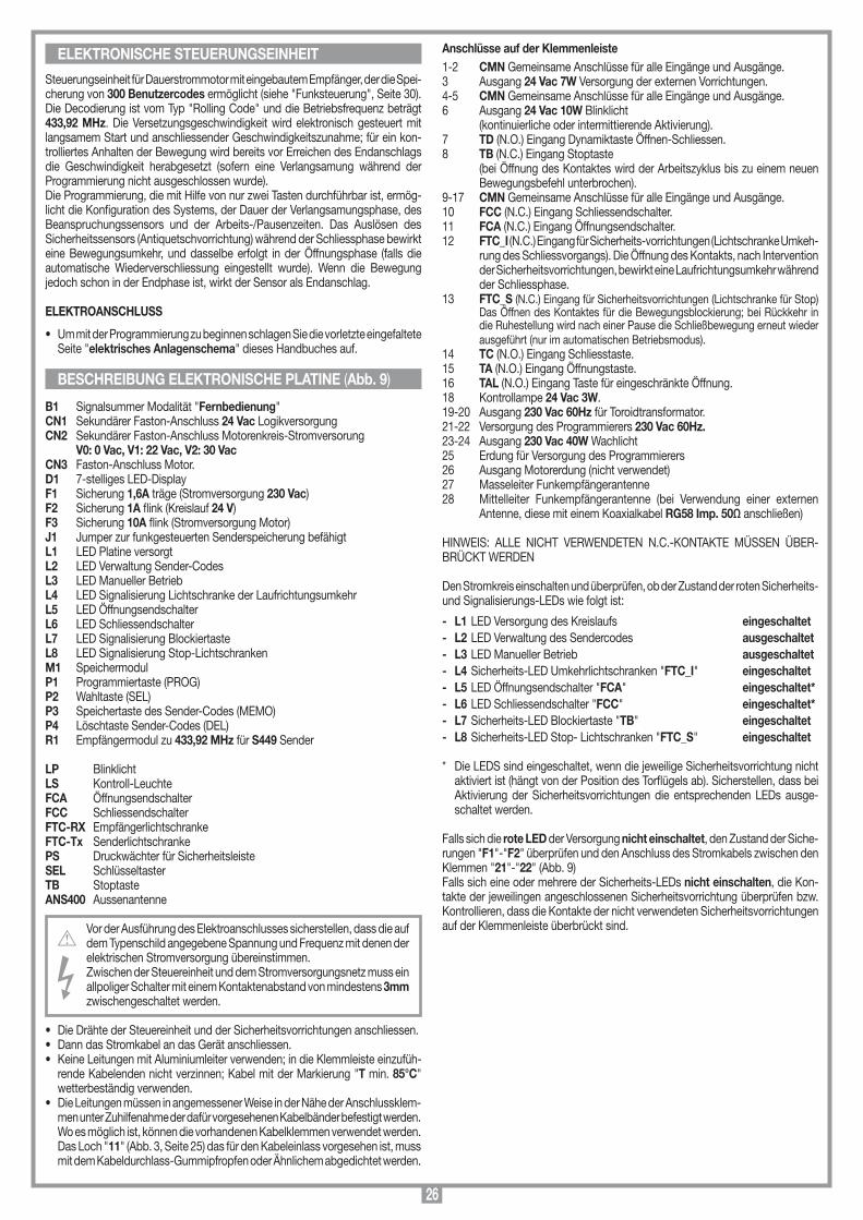
26
Steuerungseinheit für Dauerstrommotor mit eingebautem Empfänger, der die Spei-cherung von 300 Benutzercodes ermöglicht (siehe "Funksteuerung", Seite 30).Die Decodierung ist vom Typ "Rolling Code" und die Betriebsfrequenz beträgt 433,92 MHz. Die Versetzungsgeschwindigkeit wird elektronisch gesteuert mit langsamem Start und anschliessender Geschwindigkeitszunahme; für ein kon-trolliertes Anhalten der Bewegung wird bereits vor Erreichen des Endanschlags die Geschwindigkeit herabgesetzt (sofern eine Verlangsamung während der Programmierung nicht ausgeschlossen wurde). Die Programmierung, die mit Hilfe von nur zwei Tasten durchführbar ist, ermög-licht die Konfiguration des Systems, der Dauer der Verlangsamungsphase, des Beanspruchungssensors und der Arbeits-/Pausenzeiten. Das Auslösen des Sicherheitssensors (Antiquetschvorrichtung) während der Schliessphase bewirkt eine Bewegungsumkehr, und dasselbe erfolgt in der Öffnungsphase (falls die automatische Wiederverschliessung eingestellt wurde). Wenn die Bewegung jedoch schon in der Endphase ist, wirkt der Sensor als Endanschlag.
ELEKTROANSCHLUSS
• Um mit der Programmierung zu beginnen schlagen Sie die vorletzte eingefaltete Seite "elektrisches Anlagenschema" dieses Handbuches auf.
B1 Signalsummer Modalität "Fernbedienung"CN1 Sekundärer Faston-Anschluss 24 Vac Logikversorgung CN2 Sekundärer Faston-Anschluss Motorenkreis-Stromversorung V0: 0 Vac, V1: 22 Vac, V2: 30 VacCN3 Faston-Anschluss Motor.D1 7-stelliges LED-Display F1 Sicherung 1,6A träge (Stromversorgung 230 Vac)F2 Sicherung 1A flink (Kreislauf 24 V)F3 Sicherung 10A flink (Stromversorgung Motor)J1 Jumper zur funkgesteuerten Senderspeicherung befähigt L1 LED Platine versorgtL2 LED Verwaltung Sender-CodesL3 LED Manueller BetriebL4 LED Signalisierung Lichtschranke der LaufrichtungsumkehrL5 LED ÖffnungsendschalterL6 LED Schliessendschalter L7 LED Signalisierung BlockiertasteL8 LED Signalisierung Stop-LichtschrankenM1 SpeichermodulP1 Programmiertaste (PROG)P2 Wahltaste (SEL)P3 Speichertaste des Sender-Codes (MEMO)P4 Löschtaste Sender-Codes (DEL)R1 Empfängermodul zu 433,92 MHz für S449 Sender
LP Blinklicht LS Kontroll-LeuchteFCA ÖffnungsendschalterFCC SchliessendschalterFTC-RX EmpfängerlichtschrankeFTC-Tx SenderlichtschrankePS Druckwächter für SicherheitsleisteSEL SchlüsseltasterTB StoptasteANS400 Aussenantenne
Vor der Ausführung des Elektroanschlusses sicherstellen, dass die auf dem Typenschild angegebene Spannung und Frequenz mit denen der elektrischen Stromversorgung übereinstimmen.Zwischen der Steuereinheit und dem Stromversorgungsnetz muss ein allpoliger Schalter mit einem Kontaktenabstand von mindestens 3mm zwischengeschaltet werden.
• Die Drähte der Steuereinheit und der Sicherheitsvorrichtungen anschliessen.• Dann das Stromkabel an das Gerät anschliessen.• Keine Leitungen mit Aluminiumleiter verwenden; in die Klemmleiste einzufüh-
rende Kabelenden nicht verzinnen; Kabel mit der Markierung "T min. 85°C" wetterbeständig verwenden.
• Die Leitungen müssen in angemessener Weise in der Nähe der Anschlussklem-men unter Zuhilfenahme der dafür vorgesehenen Kabelbänder befestigt werden. Wo es möglich ist, können die vorhandenen Kabelklemmen verwendet werden. Das Loch "11" (Abb. 3, Seite 25) das für den Kabeleinlass vorgesehen ist, muss mit dem Kabeldurchlass-Gummipfropfen oder Ähnlichem abgedichtet werden.
BESCHREIBUNG ELEKTRONISCHE PLATINE (Abb. 9)
Anschlüsse auf der Klemmenleiste1-2 CMN Gemeinsame Anschlüsse für alle Eingänge und Ausgänge.3 Ausgang 24 Vac 7W Versorgung der externen Vorrichtungen.4-5 CMN Gemeinsame Anschlüsse für alle Eingänge und Ausgänge.6 Ausgang 24 Vac 10W Blinklicht (kontinuierliche oder intermittierende Aktivierung).7 TD (N.O.) Eingang Dynamiktaste Öffnen-Schliessen.8 TB (N.C.) Eingang Stoptaste (bei Öffnung des Kontaktes wird der Arbeitszyklus bis zu einem neuen
Bewegungsbefehl unterbrochen).9-17 CMN Gemeinsame Anschlüsse für alle Eingänge und Ausgänge.10 FCC (N.C.) Eingang Schliessendschalter.11 FCA (N.C.) Eingang Öffnungsendschalter.12 FTC_I (N.C.) Eingang für Sicherheits-vorrichtungen (Lichtschranke Umkeh-
rung des Schliessvorgangs). Die Öffnung des Kontakts, nach Intervention der Sicherheitsvorrichtungen, bewirkt eine Laufrichtungsumkehr während der Schliessphase.
13 FTC_S (N.C.) Eingang für Sicherheitsvorrichtungen (Lichtschranke für Stop) Das Öffnen des Kontaktes für die Bewegungsblockierung; bei Rückkehr in die Ruhestellung wird nach einer Pause die Schließbewegung erneut wieder ausgeführt (nur im automatischen Betriebsmodus).
14 TC (N.O.) Eingang Schliesstaste.15 TA (N.O.) Eingang Öffnungstaste.16 TAL (N.O.) Eingang Taste für eingeschränkte Öffnung.18 Kontrollampe 24 Vac 3W.19-20 Ausgang 230 Vac 60Hz für Toroidtransformator.21-22 Versorgung des Programmierers 230 Vac 60Hz.23-24 Ausgang 230 Vac 40W Wachlicht25 Erdung für Versorgung des Programmierers 26 Ausgang Motorerdung (nicht verwendet)27 Masseleiter Funkempfängerantenne 28 Mittelleiter Funkempfängerantenne (bei Verwendung einer externen
Antenne, diese mit einem Koaxialkabel RG58 Imp. 50Ω anschließen)
HINWEIS: ALLE NICHT VERWENDETEN N.C.-KONTAKTE MÜSSEN ÜBER-BRÜCKT WERDEN
Den Stromkreis einschalten und überprüfen, ob der Zustand der roten Sicherheits- und Signalisierungs-LEDs wie folgt ist:
- L1 LED Versorgung des Kreislaufs eingeschaltet- L2 LED Verwaltung des Sendercodes ausgeschaltet- L3 LED Manueller Betrieb ausgeschaltet- L4 Sicherheits-LED Umkehrlichtschranken "FTC_I" eingeschaltet- L5 LED Öffnungsendschalter "FCA" eingeschaltet*- L6 LED Schliessendschalter "FCC" eingeschaltet*- L7 Sicherheits-LED Blockiertaste "TB" eingeschaltet- L8 Sicherheits-LED Stop- Lichtschranken "FTC_S" eingeschaltet
* Die LEDS sind eingeschaltet, wenn die jeweilige Sicherheitsvorrichtung nicht aktiviert ist (hängt von der Position des Torflügels ab). Sicherstellen, dass bei Aktivierung der Sicherheitsvorrichtungen die entsprechenden LEDs ausge-schaltet werden.
Falls sich die rote LED der Versorgung nicht einschaltet, den Zustand der Siche-rungen "F1"-"F2" überprüfen und den Anschluss des Stromkabels zwischen den Klemmen "21"-"22" (Abb. 9)Falls sich eine oder mehrere der Sicherheits-LEDs nicht einschalten, die Kon-takte der jeweilingen angeschlossenen Sicherheitsvorrichtung überprüfen bzw. Kontrollieren, dass die Kontakte der nicht verwendeten Sicherheitsvorrichtungen auf der Klemmenleiste überbrückt sind.
ELEKTRONISCHE STEUERUNGSEINHEIT
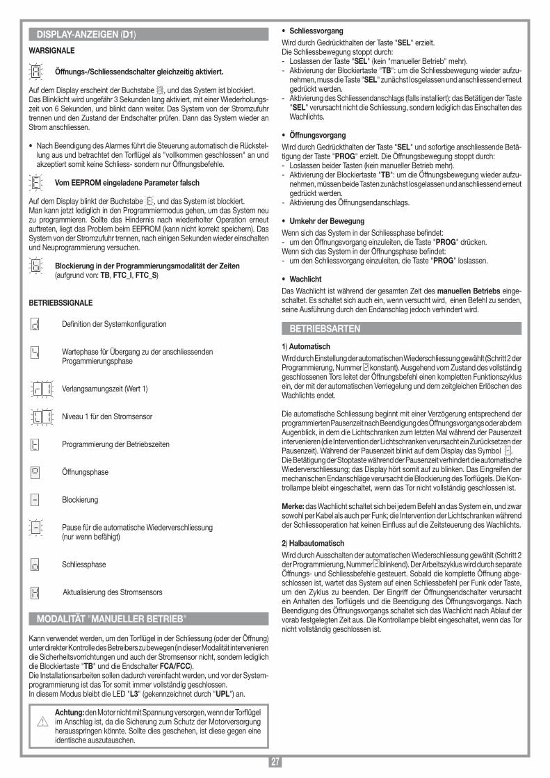
27
DISPLAY-ANZEIGEN (D1)
WARSIGNALE
Öffnungs-/Schliessendschalter gleichzeitig aktiviert.
Auf dem Display erscheint der Buchstabe , und das System ist blockiert.Das Blinklicht wird ungefähr 3 Sekunden lang aktiviert, mit einer Wiederholungs-zeit von 6 Sekunden, und blinkt dann weiter. Das System von der Stromzufuhr trennen und den Zustand der Endschalter prüfen. Dann das System wieder an Strom anschliessen.
• Nach Beendigung des Alarmes führt die Steuerung automatisch die Rückstel-lung aus und betrachtet den Torflügel als "vollkommen geschlossen" an und akzeptiert somit keine Schliess- sondern nur Öffnungsbefehle.
Vom EEPROM eingeladene Parameter falsch
Auf dem Display blinkt der Buchstabe , und das System ist blockiert.Man kann jetzt lediglich in den Programmiermodus gehen, um das System neu zu programmieren. Sollte das Hindernis nach wiederholter Operation erneut auftreten, liegt das Problem beim EEPROM (kann nicht korrekt speichern). Das System von der Stromzufuhr trennen, nach einigen Sekunden wieder einschalten und Neuprogrammierung versuchen.
Blockierung in der Programmierungsmodalität der Zeiten (aufgrund von: TB, FTC_I, FTC_S)
BETRIEBSSIGNALE Definition der Systemkonfiguration
Wartephase für Übergang zu der anschliessenden Progammierungsphase
Verlangsamungszeit (Wert 1)
Niveau 1 für den Stromsensor Programmierung der Betriebszeiten
Öffnungsphase
Blockierung
Pause für die automatische Wiederverschliessung (nur wenn befähigt)
Schliessphase Aktualisierung des Stromsensors
Kann verwendet werden, um den Torflügel in der Schliessung (oder der Öffnung) unter direkter Kontrolle des Betreibers zu bewegen (in dieser Modalität intervenieren die Sicherheitsvorrichtungen und auch der Stromsensor nicht, sondern lediglich die Blockiertaste "TB" und die Endschalter FCA/FCC). Die Installationsarbeiten sollen dadurch vereinfacht werden, und vor der System-programmierung ist das Tor somit immer vollständig geschlossen.In diesem Modus bleibt die LED "L3" (gekennzeichnet durch "UPL") an.
Achtung: den Motor nicht mit Spannung versorgen, wenn der Torflügel im Anschlag ist, da die Sicherung zum Schutz der Motorversorgung herausspringen könnte. Sollte dies geschehen, ist diese gegen eine identische auszutauschen.
MODALITÄT "MANUELLER BETRIEB"
• SchliessvorgangWird durch Gedrückthalten der Taste "SEL" erzielt.Die Schliessbewegung stoppt durch:- Loslassen der Taste "SEL" (kein "manueller Betrieb" mehr).- Aktivierung der Blockiertaste "TB": um die Schliessbewegung wieder aufzu-
nehmen, muss die Taste "SEL" zunächst losgelassen und anschliessend erneut gedrückt werden.
- Aktivierung des Schliessendanschlags (falls installiert): das Betätigen der Taste "SEL" verursacht nicht die Schliessung, sondern lediglich das Einschalten des Wachlichts.
• Öffnungsvorgang Wird durch Gedrückthalten der Taste "SEL" und sofortige anschliessende Betä-tigung der Taste "PROG" erzielt. Die Öffnungsbewegung stoppt durch:- Loslassen beider Tasten (kein manueller Betrieb mehr).- Aktivierung der Blockiertaste "TB": um die Öffnungsbewegung wieder aufzu-
nehmen, müssen beide Tasten zunächst losgelassen und anschliessend erneut gedrückt werden.
- Aktivierung des Öffnungsendanschlags.
• Umkehr der BewegungWenn sich das System in der Schliessphase befindet: - um den Öffnungsvorgang einzuleiten, die Taste "PROG" drücken.Wenn sich das System in der Öffnungsphase befindet: - um den Schliessvorgang einzuleiten, die Taste "PROG" loslassen.
• Wachlicht Das Wachlicht ist während der gesamten Zeit des manuellen Betriebs einge-schaltet. Es schaltet sich auch ein, wenn versucht wird, einen Befehl zu senden, seine Ausführung durch den Endanschlag jedoch verhindert wird.
1) AutomatischWird durch Einstellung der automatischen Wiederschliessung gewählt (Schritt 2 der Programmierung, Nummer konstant). Ausgehend vom Zustand des vollständig geschlossenen Tors leitet der Öffnungsbefehl einen kompletten Funktionszyklus ein, der mit der automatischen Verriegelung und dem zeitgleichen Erlöschen des Wachlichts endet. Die automatische Schliessung beginnt mit einer Verzögerung entsprechend der programmierten Pausenzeit nach Beendigung des Öffnungsvorgangs oder ab dem Augenblick, in dem die Lichtschranken zum letzten Mal während der Pausenzeit intervenieren (die Intervention der Lichtschranken verursacht ein Zurücksetzen der Pausenzeit). Während der Pausenzeit blinkt auf dem Display das Symbol .Die Betätigung der Stoptaste während der Pausenzeit verhindert die automatische Wiederverschliessung; das Display hört somit auf zu blinken. Das Eingreifen der mechanischen Endanschläge verursacht die Blockierung des Torflügels. Die Kon-trollampe bleibt eingeschaltet, wenn das Tor nicht vollständig geschlossen ist.
Merke: das Wachlicht schaltet sich bei jedem Befehl an das System ein, und zwar sowohl per Kabel als auch per Funk; die Intervention der Lichtschranken während der Schliessoperation hat keinen Einfluss auf die Zeitsteuerung des Wachlichts.
2) HalbautomatischWird durch Ausschalten der automatischen Wiederschliessung gewählt (Schritt 2 der Programmierung, Nummer blinkend). Der Arbeitszyklus wird durch separate Öffnungs- und Schliessbefehle gesteuert. Sobald die komplette Öffnung abge-schlossen ist, wartet das System auf einen Schliessbefehl per Funk oder Taste, um den Zyklus zu beenden. Der Eingriff der Öffnungsendschalter verursacht ein Anhalten des Torflügels und die Beendigung des Öffnungsvorgangs. Nach Beendigung des Öffnungsvorgangs schaltet sich das Wachlicht nach Ablauf der vorab festgelegten Zeit aus. Die Kontrollampe bleibt eingeschaltet, wenn das Tor nicht vollständig geschlossen ist.
BETRIEBSARTEN
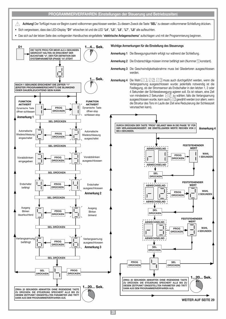
28
Dynamische Taste
öffnen-schliessenPROG
DRÜCKENDynamische Taste
öffnen-stopschliessen-stop
AutomatischeWiederschliessung
eingeschaltet
AutomatischeWiederschliessung
ausgeschaltet
SEL DRÜCKEN
SEL DRÜCKEN
FUNKTIONAKTIVIERT
Vorabblinken eingegeben
Vorabblinken ausgeschlossen
AusgangBlinken
dauerleuchtend
Verlangsamung befähigt
Verlangsamung ausgeschlossen
D1 1...4... Sek.
1... Sek.
FUNKTIONAKTIVIERT
1...20... Sek.
Anmerkung 1
SEL DRÜCKEN
Endschalterbefähigt
ZIRKA 20 SEKUNDEN ABWARTEN OHNE IRGENDEINE TASTE ZU DRÜCKEN: DIE STEUERUNG SPEICHERT ALLE BIS ZU DIESEM ZEITPUNKT EINGESTELLTEN PARAMETER UND TRITT DANN AUS DEM PROGRAMMIERVERFAHREN AUS.
SELDRÜCKEN
ABWECHSELND
ABWECHSELND
ABWECHSELND
ABWECHSELND
FESTSTEHENDER WERT
ABWECHSELND
ABWECHSELND
FESTSTEHENDER WERT
FESTSTEHENDER WERT
DURCH DRÜCKEN DER TASTE "PROG" GELANGT MAN IN DIE PHASE "B" FÜR DER VERLANGSAMUNGSZEIT. DIE EINSTELLBAREN WERTE REICHEN VON 2 BIS 4 SEKUNDEN.
SEL DRÜCKEN
1...20... Sek.ZIRKA 20 SEKUNDEN ABWARTEN OHNE IRGENDEINE TASTE ZU DRÜCKEN: DIE STEUERUNG SPEICHERT ALLE BIS ZU DIESEM ZEITPUNKT EINGESTELLTEN PARAMETER UND TRITT DANN AUS DEM PROGRAMMIERVERFAHREN AUS.
PROGDRÜCKEN
AusgangBlinkenblinkend
WAHL 1 SEKUNDEN
WAHL 2 SEKUNDEN
WAHL 4 SEKUNDEN
DIE TASTE PROG FÜR MEHR ALS 4 SEKUNDEN GEDRÜCKT HALTEN: ES ERSCHEINT DER BUCHSTABE "d", DER FÜR DEFINITION DER SYSTEMPARAMETER (PHASE "A") STEHT
NACH 1 SEKUNDE ERSCHEINT DIE ZIFFER "1" (ERSTER PROGRAMMIERSCHRITT) DIE BLINKEND ODER DAUERLEUCHTEND SEIN KANN
PROGDRÜCKEN
PROGDRÜCKEN
PROGDRÜCKEN
PROGDRÜCKEN
PROGDRÜCKEN
SELDRÜCKEN
PROGDRÜCKEN
PROGDRÜCKEN
PROGDRÜCKEN
SELDRÜCKEN
SELDRÜCKEN
SELDRÜCKEN
SEL DRÜCKEN
PROGDRÜCKEN
SEL DRÜCKEN
Anmerkung 2
Endschalterausgeschlossen
Anmerkung 3
Anmerkung 4
Achtung! Der Torflügel muss vor Beginn zuerst vollkommen geschlossen werden. Zu diesem Zweck die Taste "SEL" zu dessen vollkommener Schließung drücken.
• Sich vergewissen, dass das LED-Display "D1" erloschen ist und die LED "L4", "L5", "L6", "L7", "L8" alle aufleuchten.
• Das sich auf der letzen Seite des vorliegenden Handbuches eingefaltete "elektrische Anlagenschema" aufschlagen und mit der Programmierung beginnen.
PROGRAMMIERVERFAHREN (Einstellungen der Steuerung und Betriebszeiten)
Wichtige Anmerkungen für die Einstellung des Steuerungs
Anmerkung 1 Die Bewegungsumkehr erfolgt nur während der Schließung.
Anmerkung 2 Die Endanschläge müssen immer befähigt sein (Nummer konstant).
Anmerkung 3 Die Geschwindigkeitsabnahme muss bei Gliedertoren ausgeschlossen werden.
Anmerkung 4 Die Wahl , , muss auch durchgeführt werden, wenn die Verlangsamung ausgeschlossen wurde: jedenfalls notwendig ist die Festlegung, ob der Stromsensor als Endschalter in den letzten 1, 2 oder 4 Sekunden der Schliessbewegung agieren soll. Es ist ratsam, eine Zeit von mindestens 2 Sekunden zu wählen; falls die Verlangsamung ausgeschlossen wurde, kann auch gewählt werden (vor allem, wenn die Struktur des Tors im Laufe der Zeit eine Reduzierung der Schliesszeit verursachen kann).
WEITER AUF SEITE 29

29
SELDRÜCKEN
ABWECHSELND
ABWECHSELND
ABWECHSELND
ABWECHSELND
SELDRÜCKEN
ABWECHSELND
ABWECHSELND
20 SEKUNDEN WARTEN, OHNE IRGENDEINE TASTE ZU DRÜCKEN: DIE STEUERUNG SPEICHERT DIE BIS ZU DIESEM ZEITPUNKT EINGESTELLTEN PARAMETER UND TRITT AUS DER PROGRAMMIERUNG AUS.
DAS DRÜCKEN DER TASTE "PROG" FÜHRT ZUR PHASE "D".DIE PROGRAMMIERUNG DER BETRIEBSZEIT.
DER PHASENBEGINN WIRD DURCH DAS ERSCHEINEN FÜR ZIRKA 2 SEKUNDEN DES BUCHSTABENS "t" ANGEZEIGT. DANACH ERLISCHT DAS DISPLAY.
ES BEGINNT DIE PROGRAMMIERUNG DER ÖFFNUNGSZEIT, DIE BEI SICH BEWEGENDEM TORFLÜGEL BERECHNET WIRD. DIE AKTIVIERUNG DES ÖFFNUNGSENDSCHALTERS BESTIMMT DAS ANHALTEN DER BEWEGUNG.
ZUR BETRIEBSZEIT WIRD AUTOMATISCH EINE ZEITSPANNE VON 4 SEKUNDEN HINZUGERECHNET UND DANN BEGINNT DIE
AutomatischeWiederschliessung
befähigt
PROG DRÜCKEN
+ 4 Sek.
DIE PAUSENZEIT IST BEENDET, ES BEGINNT DIE SCHLIEßUNG UND DER STROMSENSOR FÄHRT MIT SEINER EICHUNG SOLANGE FORT, BIS DER TORFLÜGEL VOLLKOMMEN GESCHLOSSEN IST.
DAS VERFAHREN WAR NICHT ERFOLGREICH. DIE PROGRAMMIERUNG MUSS WIEDERHOLT WERDEN.
WENN DER TORFLÜGEL BEI DER VOLLKOMMENEN SCHLIEßUNG ANKOMMT, SPEICHERT DIE STEUERUNG DIE PARAMETER UND TRITT AUS DER PROGRAMMIERUNG AUS.
DAS DRÜCKEN DER "PROG"-TASTE FÜHRT ZUR EINSTELLPHASE "C" DES STROMSENSORS. DIE EINSTELLBAREN WERTE REICHEN VON 1 BIS 3. DER STANDARDWERT IST 2 (DIE WERTE 1 ODER 3 KÖNNEN BEI SCHON GEREGELTEM STROM ALS EINGESTELLT ERSCHEINEN).
SELDRÜCKEN
DIE STEUERUNG SPEICHERT DIE DATEN UND TRITT AUS DER PROGRAMMIERUNG AUS OHNE DIE EINGEGEBENEN ZEITEN ZU ÄNDERN
PROG DRÜCKEN
FESTSTEHENDERWERT
FESTSTEHENDERWERT
FESTSTEHENDERWERT
MIN.DREHMOMENT
MAX.DREHMOMENT
SELDRÜCKEN
SELDRÜCKEN
PROG DRÜCKEN
PROG DRÜCKEN
MITTLERESDREHMOMENT
PROGDRÜCKEN
AutomatischeWiederschliessung
ausgeschlossen
Wichtige Anmerkungen für die Programmierung der BetriebszeitenDas Auslösen der Umkehr-/Blockierungslichtschranken oder das Betätigen der Stoptaste während der Programmierung der Zeiten verursacht den Stillstand der Bewegung, während das Blinklicht jedoch aktiviert bleibt und signalisiert, dass der Programmierer in der aktiven Phase ist; auf dem Display blinkt die Anzeige . Nach Ende der Alarmsituation oder nachdem die Stoptaste losgelassen wurde (aktiviert nur solange man gedrückt hält) setzt jedoch die Bewegung des Torflügels wieder automatisch ein. In dieser Situation wird die Berechnung der Betriebszeit verfälscht, und die Programmierung muss wiederholt werden.
Achtung ! Die Betätigung der Taste "SEL" in der Programmierphase der Zeiten (nach Bewegung des Törflügels) verhindert die korrekte Vervollständigung des Verfahrens.
Achtung! Die Betriebszeiten so programmieren, dass immer die komplette Öffnung des Torflügels erfolgt. Das Ende der Program-mierung wird durch Aufleuchten des Wachlichts (dessen Aktivie-rungszeit bereits programmiert ist) angezeigt.
Wachlichtszeit = Öffnungszeit + Pausenzeit + Schließzeit + 30 Sekunden. Wird der halbautomatische Betrieb gewählt, kann durch Programmierung einer langen Pausenzeit (max. 5 Min.) die Aktivierungszeit des Wachlichts verlängert werden.
StromsensorDie Steuerung kontrolliert die Stromaufnahme des Motors und kann somit eine übermäßige Belastungszunahme über die Normalbetriebswertgrenzen hinaus ermitteln.Zur Gewährleistung der ordentlichen Betriebsweise auch bei unterschied-lichen klimatischen und mechanischen Bedingungen führt die Steuerung beim Eintreffen eines Öffnungsbefehls in der Betriebsstellung "vollständig geschlossen" jedes Mal eine Selbsteichung durch. Dies ermöglicht dem System eventuelle Erhöhungen im Vergleich zum Zeitpunkt der Programmierung bei den Bewegungswiderständen zu erfassen und so auszugleichen, dass die Kraftaufwendung zum Anhalten des Torflügels nicht zu gering ist und somit eine optimale Betriebsweise gewährleistet werden kann.
Achtung: Während der Selbsteichung greift der Stromsensor nicht ein. Aus diesem Grund sollte der Torflügel während der ersten Sekunden bei der Öffnungsbewegung nicht forciert werden.
Die Steuerung der Arbeitszeiten ermöglicht die Kontrolle der Torflügelposi-tion. Falls zum Zeitpunkt eines Stromausfalls nicht einer der beiden Endan-schlagsschalter aktiv sein sollte, verliert der Programmierer die Speicherung der erreichten Position des Torflügels. Der Zustand des Tors wird als völlig geschlossen vorausgesetzt, und die Öffnung kann somit wieder eingeleitet werden. Die Betriebszeitenverwaltung stellt sicher, dass der nachfolgende Schließvorgang wieder komplett ausgeführt wird.
Achtung! Aus diesem Grund ist es unbedingt notwendig, den mechanischen Öffnungs-Endansschlag zu verwenden, und bei der Programmierung niemals die Funktion der Endanschlagsschalter auszuschliessen (Schritt 4, Phase A).
• Bei wiederholter Laufrichtungsumkehr mit entsprechendem Stillstand der Bewegung und langsamem Start könnte es zu Veränderungen in der Zeitüberwachung und zu einem Aussetzen der Verlangsamung vor Ankunft am Endanschlag kommen. Geschieht dies während der Schliessphase, erfolgt die Umkehren der Bewegung; die Arbeitszeiten werde jedoch nach der vollständigen Öffnung wieder hergestellt.
ZEITGESTEUERTER ENDSCHALTER
FORTFÜHRUNG VON SEITE 28
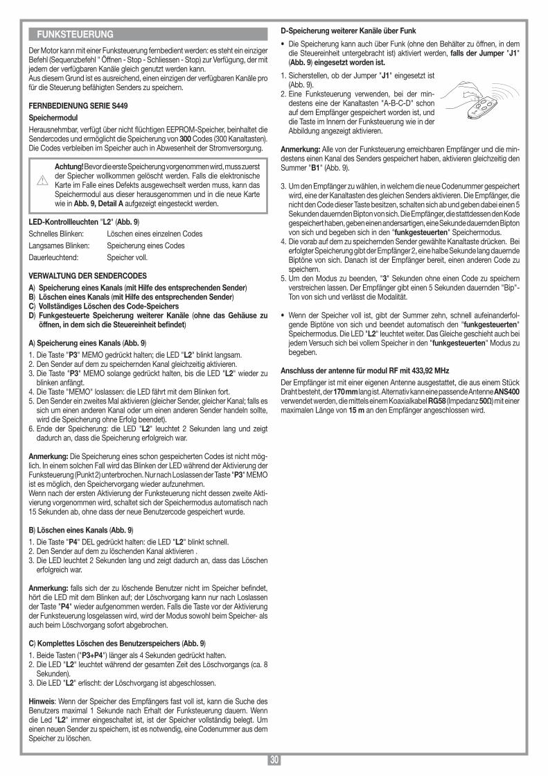
30
MEMORIZZAZIONE CODICE TX-RX
RCQ449100
13-04-2001
DM0531 Description :
Product Code :
Date :
Drawing number :
P.J.Heath
CARDIN ELETTRONICA S.p.A - 31020 San Vendemiano (TV) Italy - via Raffaello, 36 Tel: 0438/401818 Fax: 0438/401831
Draft :
All rights reserved. Unauthorised copying or use of the information contained in this document is punishable by law
MR
Der Motor kann mit einer Funksteuerung fernbedient werden: es steht ein einziger Befehl (Sequenzbefehl " Öffnen - Stop - Schliessen - Stop) zur Verfügung, der mit jedem der verfügbaren Kanäle gleich genutzt werden kann. Aus diesem Grund ist es ausreichend, einen einzigen der verfügbaren Kanäle pro für die Steuerung befähigten Senders zu speichern.
FERNBEDIENUNG SERIE S449SpeichermodulHerausnehmbar, verfügt über nicht flüchtigen EEPROM-Speicher, beinhaltet die Sendercodes und ermöglicht die Speicherung von 300 Codes (300 Kanaltasten). Die Codes verbleiben im Speicher auch in Abwesenheit der Stromversorgung.
Achtung! Bevor die erste Speicherung vorgenommen wird, muss zuerst der Spiecher wollkommen gelöscht werden. Falls die elektronische Karte im Falle eines Defekts ausgewechselt werden muss, kann das Speichermodul aus dieser herausgenommen und in die neue Karte wie in Abb. 9, Detail A aufgezeigt eingesteckt werden.
LED-Kontrollleuchten "L2" (Abb. 9)Schnelles Blinken: Löschen eines einzelnen CodesLangsames Blinken: Speicherung eines CodesDauerleuchtend: Speicher voll.
VERWALTUNG DER SENDERCODESA) Speicherung eines Kanals (mit Hilfe des entsprechenden Sender)B) Löschen eines Kanals (mit Hilfe des entsprechenden Sender)C) Vollständiges Löschen des Code-SpeichersD) Funkgesteuerte Speicherung weiterer Kanäle (ohne das Gehäuse zu
öffnen, in dem sich die Steuereinheit befindet)
A) Speicherung eines Kanals (Abb. 9)1. Die Taste "P3" MEMO gedrückt halten; die LED "L2" blinkt langsam.2. Den Sender auf dem zu speichernden Kanal gleichzeitig aktivieren.3. Die Taste "P3" MEMO solange gedrückt halten, bis die LED "L2" wieder zu
blinken anfängt.4. Die Taste "MEMO" loslassen: die LED fährt mit dem Blinken fort.5. Den Sender ein zweites Mal aktivieren (gleicher Sender, gleicher Kanal; falls es
sich um einen anderen Kanal oder um einen anderen Sender handeln sollte, wird die Speicherung ohne Erfolg beendet).
6. Ende der Speicherung: die LED "L2" leuchtet 2 Sekunden lang und zeigt dadurch an, dass die Speicherung erfolgreich war.
Anmerkung: Die Speicherung eines schon gespeicherten Codes ist nicht mög-lich. In einem solchen Fall wird das Blinken der LED während der Aktivierung der Funksteuerung (Punkt 2) unterbrochen. Nur nach Loslassen der Taste "P3" MEMO ist es möglich, den Speichervorgang wieder aufzunehmen.Wenn nach der ersten Aktivierung der Funksteuerung nicht dessen zweite Akti-vierung vorgenommen wird, schaltet sich der Speichermodus automatisch nach 15 Sekunden ab, ohne dass der neue Benutzercode gespeichert wurde.
B) Löschen eines Kanals (Abb. 9)1. Die Taste "P4" DEL gedrückt halten: die LED "L2" blinkt schnell.2. Den Sender auf dem zu löschenden Kanal aktivieren .3. Die LED leuchtet 2 Sekunden lang und zeigt dadurch an, dass das Löschen
erfolgreich war.
Anmerkung: falls sich der zu löschende Benutzer nicht im Speicher befindet, hört die LED mit dem Blinken auf; der Löschvorgang kann nur nach Loslassen der Taste "P4" wieder aufgenommen werden. Falls die Taste vor der Aktivierung der Funksteuerung losgelassen wird, wird der Modus sowohl beim Speicher- als auch beim Löschvorgang sofort abgebrochen.
C) Komplettes Löschen des Benutzerspeichers (Abb. 9)1. Beide Tasten ("P3+P4") länger als 4 Sekunden gedrückt halten.2. Die LED "L2" leuchtet während der gesamten Zeit des Löschvorgangs (ca. 8
Sekunden).3. Die LED "L2" erlischt: der Löschvorgang ist abgeschlossen.
Hinweis: Wenn der Speicher des Empfängers fast voll ist, kann die Suche des Benutzers maximal 1 Sekunde nach Erhalt der Funksteuerung dauern. Wenn die Led "L2" immer eingeschaltet ist, ist der Speicher vollständig belegt. Um einen neuen Sender zu speichern, ist es notwendig, eine Codenummer aus dem Speicher zu löschen.
D-Speicherung weiterer Kanäle über Funk
• Die Speicherung kann auch über Funk (ohne den Behälter zu öffnen, in dem die Steuereinheit untergebracht ist) aktiviert werden, falls der Jumper "J1" (Abb. 9) eingesetzt worden ist.
1. Sicherstellen, ob der Jumper "J1" eingesetzt ist (Abb. 9).
2. Eine Funksteuerung verwenden, bei der min-destens eine der Kanaltasten "A-B-C-D" schon auf dem Empfänger gespeichert worden ist, und die Taste im Innern der Funksteuerung wie in der Abbildung angezeigt aktivieren.
Anmerkung: Alle von der Funksteuerung erreichbaren Empfänger und die min-destens einen Kanal des Senders gespeichert haben, aktivieren gleichzeitig den Summer "B1" (Abb. 9).
3. Um den Empfänger zu wählen, in welchem die neue Codenummer gespeichert wird, eine der Kanaltasten des gleichen Senders aktivieren. Die Empfänger, die nicht den Code dieser Taste besitzen, schalten sich ab und geben dabei einen 5 Sekunden dauernden Bipton von sich. Die Empfänger, die stattdessen den Kode gespeichert haben, geben einen andersartigen, eine Sekunde dauernden Bipton von sich und begeben sich in den "funkgesteuerten" Speichermodus.
4. Die vorab auf dem zu speichernden Sender gewählte Kanaltaste drücken. Bei erfolgter Speicherung gibt der Empfänger 2, eine halbe Sekunde lang dauernde Biptöne von sich. Danach ist der Empfänger bereit, einen anderen Code zu speichern.
5. Um den Modus zu beenden, "3" Sekunden ohne einen Code zu speichern verstreichen lassen. Der Empfänger gibt einen 5 Sekunden dauernden "Bip"-Ton von sich und verlässt die Modalität.
• Wenn der Speicher voll ist, gibt der Summer zehn, schnell aufeinanderfol-gende Biptöne von sich und beendet automatisch den "funkgesteuerten" Speichermodus. Die LED "L2" leuchtet weiter. Das Gleiche geschieht auch bei jedem Versuch sich bei vollem Speicher in den "funkgesteuerten" Modus zu begeben.
Anschluss der antenne für modul RF mit 433,92 MHzDer Empfänger ist mit einer eigenen Antenne ausgestattet, die aus einem Stück Draht besteht, der 170 mm lang ist. Alternativ kann eine passende Antenne ANS400 verwendet werden, die mittels einem Koaxialkabel RG58 (Impedanz 50Ω) mit einer maximalen Länge von 15 m an den Empfänger angeschlossen wird.
FUNKSTEUERUNG
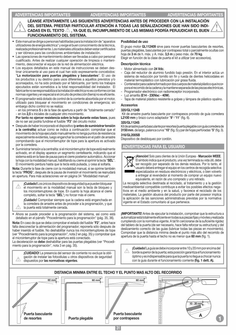
31
60 mm60 mm 60 mm
SCALA: 1:2
Prodotti Technocity
GL1024 (traino)
06-04-98
DI0059 Description :
Product Code :
Date :
Drawing number :
P.J.Heath
CARDIN ELETTRONICA S.p.A - 31020 San Vendemiano (TV) Italy - via Raffaello, 36 Tel: 0438/401818 Fax: 0438/401831
Draft :
All rights reserved. Unauthorised copying or use of the information contained in this document is punishable by law
Distanze tra il soffitto e la porta
• Este manual se dirige a personas habilitadas para la instalación de "aparatos utilizadores de energía eléctrica" y exige el buen conocimiento de la técnica, realizada profesionalmente. Los materiales utilizados deben estar certificados y ser idóneos para las condiciones ambientales de instalación.
• Las operaciones de mantenimiento deben ser llevadas a cabo por personal cualificado. Antes de realizar cualquier operación de limpieza o manteni-miento, desconectar el equipo de la red de alimentación eléctrica.
• Los equipos detallados en este manual de instrucciones se deben des-tinar únicamente al uso para el cual han sido expresamente concebidos: "La motorización para puertas plegables y basculantes". El uso de los productos y su destino para usos diferentes a aquéllos previstos y/o aconsejados, no ha sido probado por el fabricante, por tanto los trabajos ejecutados están sometidos a la total responsabilidad del instalador. El fabricante no se responsabiliza si la instalación eléctrica no es conforme con las normas vigentes y en especial si el circuito de protección (tierra) no es eficiente.
• El programador está dotado de control de la corriente absorbida por el motor, utilizado para bloquear el movimiento en condiciones de emergencia; sin embargo dicho control no se realiza:- en los primeros 5 s de la fase de apertura a partir de "totalmente cerrado"- en los 2,5 s iniciales de cualquier otro movimiento.
Por tanto no ejercer resistencia sobre la hoja durante estas fases, pues de no ser así podría fundirse el fusible "F3" del circuito motor.
• Después de haber incorporado el dispositivo (y antes de suministrar tensión a la centralita) actuar como se indica a continuación: comprobar que el movimiento de la hoja ejecutado manualmente no tenga puntos de resistencia especialmente evidentes, luego enganchar la corredera en el patín de arrastre comprobando que el microinterruptor de tope para la apertura es activado por la corredera.
• Suministrar tensión a la centralita: si el microinterruptor de tope está realmente activado, en el display aparece un segmento centelleante, indicando que el sistema está en la fase de pausa para el cierre posterior automático. Accionar la hoja con la modalidad manual, habilitando su cierre al oprimir la tecla "SEL". El movimiento perdura hasta que la tecla está pulsada, y cesa al soltarla.
Nota: Durante la fase de cierre con la modalidad manual, si se oprime también la tecla "PROG", después de la pausa de inversión el movimiento se reanudará en apertura. Para más aclaraciones ver en página 34 "Modalidad manual".
¡Cuidado! Los únicos dispositivos de seguridad que pueden bloquear el movimiento en la modalidad manual son la tecla de bloqueo y los microinterruptores de tope. En cuanto la hoja alcance el cierre completo, soltar la tecla "SEL"; no forzar más el cierre.¡Cuidado! Comprobar siempre que la cadena está enganchada en la corredera de arrastre antes de proceder a la programación, y que la puerta está totalmente cerrada.
• Ahora se puede proceder a la programación del sistema, así como está detallado en el párrafo "Procedimiento para la programación" (pág. 35, 36).
Nota: En caso de que se deba comprobar el estado del fusible "F2", antes hace falta desconectar la alimentación del programador; reponerla sólo después de haber inserido el fusible. No deshabilitar nunca los microinterruptores de tope (ver "Procedimiento para la programación", nota 2 en pág. 35) y comprobar que el microinterruptor de tope para la apertura está conectado.La deceleración se debe deshabilitar para las puertas plegables (ver "Procedi-miento para la programación", nota 3 en pág. 35).
¡CUIDADO! La presencia del sensor de corriente no excluye la obli-gación de instalar las fotocélulas u otros dispositivos de seguridad dispuestos por las normativas vigentes.
Posibilidad de usoEl grupo motor GL112409 sirve para mover puertas basculantes de resortes, puertas plegables, basculantes por contrapeso total o parcialmente ocultas con hoja de 3 m de h. máx. y A. máx. 3,5 m y peso máx. de 70 kg.Elegir en función de la clase de puerta el kit a utilizar (ver accesorios).
Descripción técnica- Motor alimentado con 24 Vdc.- Caja del reductor de aluminio fundido bajo presión. En el interior actúa un
sistema de reducción por tornillo sin fin y rueda de dientes helicoidales en material termoplástico con lubricación por grasa fluida.
- Contenedor para cadena formado por dos cuerpos de material plástico que incor-pora el recorrido de la cadena y la mantiene separada de las piezas electrónicas.
- Programador electrónico con radiorreceptor incorporado.- Luz amarilla (E14 - 230Vac - 40W).- Tapa de material plástico resistente a golpes y lámpara de plástico opalino.
Accesorios320/GL1124B Kit de arrastre puerta basculante por contrapesos provisto de guía corredera L2100 mm y brazo curvo adaptador "9"-"11" (fig. 6).320/GL1124SKit de arrastre puerta basculante por resortes/puerta plegable con guía corredera de 3150 mm. de largo, palanca curva "10" (fig. 5) y par de hojas perforadas "5" (fig. 3).316/GL200SBDispositivo de desbloqueo por cordón.
¡Atención! Solo para clientes de la Unión Europea - Marcación WEEE.El símbolo indica que el producto, una vez terminada su vida útil, debe ser recogido por separado de los demás residuos. Por lo tanto, el usuario deberá entregar el equipo en los centros de recogida selectiva especializados en residuos electrónicos y eléctricos, o bien volverlo a entregar al revendedor al momento de comprar un equipo nuevo equivalente, en razón de uno comprado y uno retirado.
La recogida selectiva destinada al reciclado, al tratamiento y a la gestión medioambiental compatible contribuye a evitar los posibles efectos nega-tivos en el medio ambiente y en la salud, y favorece el reciclado de los materiales. La gestión abusiva del producto por parte del posesor implica la aplicación de las sanciones administrativas previstas por la normativa vigente en el Estado comunitario al que pertenece.
¡IMPORTANTE! Antes de ejecutar la instalación, comprobar que la estructura a automatizar está totalmente eficiente en todas sus piezas fijas y móviles y realizada cumpliendo con la normativa vigente. A tal fin cerciorarse de la suficiente rigidez del tablero de la puerta (de ser necesario, hace falta reforzar su estructura) y del deslizamiento correcto de las guías (lubricar todas las piezas en movimiento). Comprobar que la distancia mínima desde el punto más alto del recorrido de apertura de la puerta hasta el techo no es menor que 60 mm (fig. 1).
¡Cuidado! La guía se debe incorporar entre 10 y 20 mm por encima del borde superior de la puerta; esta posición garantiza el funcionamiento óptimo y es indispensable para que la puerta no llegue a chocar nunca con la guía durante el funcionamiento corriente (fig. 1 dett. A).
DISTANCIA MINIMA ENTRE EL TECHO Y EL PUNTO MAS ALTO DEL RECORRIDO
Puerta basculantede resortes Puerta plegable
Puerta basculantepor contrapesos
10 - 20 mm
A
SCALA: 1:2
Prodotti Technocity
GL1024 (traino)
26-01-2000
DI0142 Description :
Product Code :
Date :
Drawing number :
P.J.Heath
CARDIN ELETTRONICA S.p.A - 31020 San Vendemiano (TV) Italy - via Raffaello, 36 Tel: 0438/401818 Fax: 0438/401831
Draft :
All rights reserved. Unauthorised copying or use of the information contained in this document is punishable by law
INSTALLAZIONE PORTA A CONTRAPPESI spazio di 10 mm
1
ADVERTENCIAS IMPORTANTES ADVERTENCIAS IMPORTANTES ADVERTENCIAS IMPORTANTESLÉANSE ATENTAMENTE LAS SIGUIENTES ADVERTENCIAS ANTES DE PROCEDER CON LA INSTALACIÓN DEL SISTEMA. PRESTAR PARTICULAR ATENCIÓN A TODAS LAS SEÑALIZACIONES QUE HAN SIDO INDI-CADAS EN EL TEXTO , YA QUE EL INCUMPLIMIENTO DE LAS MISMAS PODRÍA PERJUDICAR EL BUEN FUNCIONAMIENTO DEL SISTEMA.
ADVERTENCIAS PARA EL USUARIO

32
10
7 8
SCALA: 1:2
Prodotti Technocity
GL1024 (traino)
07-04-98
DI0061 Description :
Product Code :
Date :
Drawing number :
P.J.Heath
CARDIN ELETTRONICA S.p.A - 31020 San Vendemiano (TV) Italy - via Raffaello, 36 Tel: 0438/401818 Fax: 0438/401831
Draft :
All rights reserved. Unauthorised copying or use of the information contained in this document is punishable by law
INSTALLAZIONE PORTONE SEZIONALE/BASCULANTE A MOLLA
A
SCALA: 1:2
Prodotti Technocity
GL1024 (traino)
06-04-98
DI0060 Description :
Product Code :
Date :
Drawing number :
P.J.Heath
CARDIN ELETTRONICA S.p.A - 31020 San Vendemiano (TV) Italy - via Raffaello, 36 Tel: 0438/401818 Fax: 0438/401831
Draft :
All rights reserved. Unauthorised copying or use of the information contained in this document is punishable by law
INSTALLAZIONE A SOFFITTO
5
5a
¡Importante! La guía de aluminio se suministra con medidas estándares (ver accesorios). Si se requiere una medida inferior que suponga el corte de la guía, está prohibido acoplar el lado recortado con el operador.1. Introducir el cursor "A", la cadena y los elementos de soporte "C" en su
alojamiento "" de la guía "B".2. Disponer la guía "B" en contacto con el extremo del operador "D", utilizando
un martillo de goma "E". Quitar las virutas (entre el extremo de la guía y la base de plástico) que se van amontonando durante la incorporación de la guía.
¡Cuidado! No debe haber discontinuidad en el recorrido de la cadena entre el operador y la guía de aluminio.
3. Incorporar los cuatro tornillos y arandelas "L" y apretar debida-mente.
4. Inserir la corredera de arrastre "F" en la guía "B" hasta que se enganche en el cursor "A" con el elemento agujereado hacia la parte opuesta al operador "D".
5. Fijar el soporte del microinterruptor de tope "G" en la guía "B" (ver detalle enganche). Después será posible deslizarlo hasta el punto deseado.
Montaje de la guía (fig. 3) • Colocar las escuadras anteriores de fijación de la guía "4", juntándolas con las
placas correspondientes (introducidas en las ranuras específicas de la guía), por medio de los tornillos suministrados.
• Incorporar las hojas perforadas de soporte guía "5" colocándolas en los tornillos de fijación del actuador "L" (fig. 2) en la guía y utilizando las placas correspon-dientes "10" en la posición intermedia (aproximadamente 1/3 hacia adelante).
• Fijar el cordón con pomo de desbloqueo "E" en el elemento de enganche/desenganche de la corredera (fig. 3a).
• Eliminar el sistema de cierre de la puerta sustituyéndolo por el desbloqueo con cordón (ver fig. 3a).
• La guía se debe montar perpendicular a la puerta y paralela al techo.
• Medir la mitad precisa de la puerta y marcar, perpendicularmente a la puerta, su medida en el techo para facilitar la colocación de la guía.
• Fijar las escuadras anteriores de la guía en el travesaño superior fijo de la puerta, utilizando unos tornillos M6 o autorroscantes 6,3 x 19 (fig. 4).
• Marcar la posición de los puntos de fijación de las escuadras agujereadas de soporte de la guía posteriores "5" (fig. 4) y en la eventualidad, también las centrales "5a" (fig. 4) en el techo, refiriéndose a la marca puesta en el techo anteriormente. Taladrar con una broca de 10 para tacos expansivos.
• Fijar las escuadras agujereadas de soporte de la guía en el techo, perpendi-cularmente a éste, con unos tornillos M6.
• Apretar los tornillos anteriores de fijación de la guía.• Desbloquear la corredera de arrastre tirándola suavemente y deslizándola por
la guía hasta que alcance la parte delantera, cerca de la puerta.
Luego, según el caso:
A) Puerta plegable, basculante de resortes (fig. 5)• Fijar la escuadra de arrastre "8" en la parte de
arriba de la puerta, en el medio que se había deter-minado con antelación, por medio de 6 tornillos autorroscantes 4,9 x 19 o remaches.
• Conectar la palanca curva "10" en la escuadra de arrastre y la corredera de arrastre "8" mediante el perno y los anillos de retención suministrados. Para aprovechar al máximo la carrera de la corredera podría volverse necesario, según el caso, acortar dicha palanca utilizando los agujeros dispuestos y desplazar el inicio de la guía (aumentar la medida "A" fig. 4 por medio del distanciador correspondiente).
B) Puerta basculante por contrapesos (fig. 6)• Fijar el brazo curvo adaptador "9" en el medio y obli-
gatoriamente a ras de la parte superior de la puerta "12", por medio de 4+4 tornillos autorroscantes 4,9 x 19. Si el punto inferior de fijación no coincide con un travesaño "13" de la estructura de la puerta, hace falta incorporar un refuerzo "14".
• Conectar el elemento agujereado "11" con la corredera de arrastre por medio del perno y de los anillos de retención suministrados y con el brazo curvo adaptador "9" mediante 2 tornillos M8 x 20 y las tuercas correspondientes.
• Comprobar el funcionamiento correcto: a la carrera de la corredera debe corresponder la apertura total de la puerta.
• Comprobar el ajuste de la puerta (con el motor desbloqueado debe estar parada, en equilibrio, en cualquier punto de apertura).
MantenimientoPrueba periódica de las piezas en movimiento (pernos, cables) y su lubricación eventual.
OPERACIONES PREVIAS AL MONTAJE INSTALACIÓN
Detalle enganche soporte micro-interruptor de tope
Leyenda1 Actuador electromecánico 24V con programador2 Corredera de arrastre3 Guía para puerta basculante por contrapesos de 2100 mm de largo4 Escuadras anteriores de fijación guía
5 Escuadras agujereadas de soporte guía6 Guía para puerta plegable de 3150 mm de largo7 Palanca curva8 Escuadra de arrastre9 Brazo curvo adaptador 10 Placas de fijación11 Orificio de entrada de los cables.
montaggio motore
GL1124
19-10-98
DM0380 Description :
Product Code :
Date :
Drawing number :
P.J.Heath
CARDIN ELETTRONICA S.p.A - 31020 San Vendemiano (TV) Italy - via Raffaello, 36 Tel: 0438/401818 Fax: 0438/401831
Draft :
All rights reserved. Unauthorised copying or use of the information contained in this document is punishable by law
GL1124
1
4
5
2
93
10
8
7
4
6
2
5
10
11
5
55
SCALA: 1:2
Prodotti Technocity
GL1024 (traino)
07-04-98
DI0062 Description :
Product Code :
Date :
Drawing number :
P.J.Heath
CARDIN ELETTRONICA S.p.A - 31020 San Vendemiano (TV) Italy - via Raffaello, 36 Tel: 0438/401818 Fax: 0438/401831
Draft :
All rights reserved. Unauthorised copying or use of the information contained in this document is punishable by law
INSTALLAZIONE BASCULANTE A TOTALE O PARZIALE RIENTRANCE
30 mm min
9
11
12
14
13
montaggio motore preliminari
GL1024
21-05-98
DM0368 Description :
Product Code :
Date :
Drawing number :
P.J.Heath
CARDIN ELETTRONICA S.p.A - 31020 San Vendemiano (TV) Italy - via Raffaello, 36 Tel: 0438/401818 Fax: 0438/401831
Draft :
All rights reserved. Unauthorised copying or use of the information contained in this document is punishable by law
GL1024
B
G2ACD
F
E
L
G1
6
MANIOBRA MANUAL
4
3
5
2
El motorreductor es tipo irreversible y garantiza el bloqueo de la puerta durante el cierre. Para el desblo-queo de la misma, que debe realizarse en ausencia de energía eléctrica, proceder de la siguiente manera:• Halar el cordel hacia la puerta, tal y como se indica en la figura 7; el motor se desbloquea y la puerta se puede manobriar manualmente.¡Atención! No utilizar el cordel para mover la puerta, sino utilizar siempre el tirador de la puerta misma.• Para bloquear de nuevo el motor, halar el cordel hacia el sentido correspondiente, tal y como se indica en la figura 8, y luego cerrar la puerta. El desbloqueo de ésta se rearma automáticamente.
7 8
100
mm
ED
A
B
C
E
PREMONTAGGIO
GL1024
06-04-98
DM0353 Description :
Product Code :
Date :
Drawing number :
P.J.Heath
CARDIN ELETTRONICA S.p.A - 31020 San Vendemiano (TV) Italy - via Raffaello, 36 Tel: 0438/401818 Fax: 0438/401831
Draft :
All rights reserved. Unauthorised copying or use of the information contained in this document is punishable by law
GL1024 SBLOCCO A CORDINO
3a
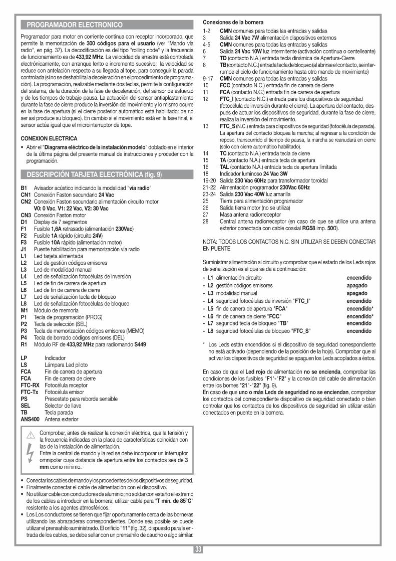
33
Programador para motor en corriente continua con receptor incorporado, que permite la memorización de 300 códigos para el usuario (ver "Mando vía radio", en pág. 37). La decodificación es del tipo "rolling code" y la frecuencia de funcionamiento es de 433,92 MHz. La velocidad de arrastre está controlada electrónicamente, con arranque lento e incremento sucesivo; la velocidad se reduce con antelación respecto a su llegada al tope, para conseguir la parada controlada (si no se deshabilita la deceleración en el procedimiento de programa-ción). La programación, realizable mediante dos teclas, permite la configuración del sistema, de la duración de la fase de deceleración, del sensor de esfuerzo y de los tiempos de trabajo-pausa. La actuación del sensor antiaplastamiento durante la fase de cierre produce la inversión del movimiento y lo mismo ocurre en la fase de apertura (si el cierre posterior automático está habilitado: de no ser así produce su bloqueo). En cambio si el movimiento está en la fase final, el sensor actúa igual que el microinterruptor de tope.
CONEXION ELECTRICA• Abrir el "Diagrama eléctrico de la instalación modelo" doblado en el interior
de la última página del presente manual de instrucciones y proceder con la programación.
B1 Avisador acústico indicando la modalidad "vía radio"CN1 Conexión Faston secundario 24 VacCN2 Conexión Faston secundario alimentación circuito motor V0: 0 Vac, V1: 22 Vac, V2: 30 VacCN3 Conexión Faston motorD1 Display de 7 segmentosF1 Fusible 1,6A retrasado (alimentación 230Vac)F2 Fusible 1A rápido (circuito 24V)F3 Fusible 10A rápido (alimentación motor)J1 Puente habilitación para memorización vía radioL1 Led tarjeta alimentada L2 Led de gestión códigos emisoresL3 Led de modalidad manualL4 Led de señalización fotocélulas de inversiónL5 Led de fin de carrera de aperturaL6 Led de fin de carrera de cierreL7 Led de señalización tecla de bloqueoL8 Led de señalización fotocélulas de bloqueoM1 Módulo de memoriaP1 Tecla de programación (PROG)P2 Tecla de selección (SEL)P3 Tecla de memorización códigos emisores (MEMO)P4 Tecla de borrado códigos emisores (DEL)R1 Módulo RF de 433,92 MHz para radiomando S449
LP Indicador LS Lámpara Led pilotoFCA Fin de carrera de aperturaFCA Fin de carrera de cierreFTC-RX Fotocélula receptorFTC-Tx Fotocélula emisorPS Presostato para reborde sensibleSEL Selector de llaveTB Tecla paradaANS400 Antena exterior
Comprobar, antes de realizar la conexión eléctrica, que la tensión y la frecuencia indicadas en la placa de características coincidan con las de la instalación de alimentación.Entre la central de mando y la red se debe incorporar un interruptor omnipolar cuya distancia de apertura entre los contactos sea de 3 mm como mínimo.
• Conectar los cables de mando y los procedentes de los dispositivos de seguridad.• Finalmente conectar el cable de alimentación con el dispositivo.• No utilizar cable con conductores de aluminio; no soldar con estaño el extremo
de los cables a introducir en la bornera; utilizar cable para "T mín. de 85°C" resistente a los agentes atmosféricos.
• Los Los conductores se tienen que fijar oportunamente cerca de las borneras utilizando las abrazaderas correspondientes. Donde sea posible se puede utilizar el prensahilo suministrado. El orificio "11" (fig. 32), dispuesto para la en-trada de los cables, se debe sellar con un prensahilo de caucho o algo similar.
DESCRIPCIÓN TARJETA ELECTRÓNICA (fig. 9)
PROGRAMADOR ELECTRONICO Conexiones de la bornera1-2 CMN comunes para todas las entradas y salidas3 Salida 24 Vac 7W alimentación dispositivos externos4-5 CMN comunes para todas las entradas y salidas6 Salida 24 Vac 10W luz intermitente (activación continua o centelleante)7 TD (contacto N.A.) entrada tecla dinámica de Apertura-Cierre8 TB (contacto N.C.) entrada tecla de bloqueo (al abrirse el contacto, se inter-
rumpe el ciclo de funcionamiento hasta otro mando de movimiento)9-17 CMN comunes para todas las entradas y salidas10 FCC (contacto N.C.) entrada fin de carrera de cierre 11 FCA (contacto N.C.) entrada fin de carrera de apertura12 FTC_I (contacto N.C.) entrada para los dispositivos de seguridad (fotocélula de inversión durante el cierre). La apertura del contacto, des-
pués de actuar los dispositivos de seguridad, durante la fase de cierre, realiza la inversión del movimiento.
13 FTC_S (N.C.) entrada para dispositivos de seguridad (fotocélula de parada). La apertura del contacto bloquea la marcha; al regresar a la condición de reposo, transcurrido el tiempo de pausa, la marcha se reanudará en cierre (sólo con cierre automático habilitado).
14 TC (contacto N.A.) entrada tecla de cierre15 TA (contacto N.A.) entrada tecla de apertura16 TAL (contacto N.A.) entrada tecla de apertura limitada18 Indicador luminoso 24 Vac 3W19-20 Salida 230 Vac 60Hz para transformador toroidal21-22 Alimentación programador 230Vac 60Hz23-24 Salida 230 Vac 40W luz amarilla25 Tierra para alimentación programador 26 Salida tierra motor (no se utiliza)27 Masa antena radiorreceptor28 Central antena radiorreceptor (en caso de que se utilice una antena
exterior conectada con cable coaxial RG58 imp. 50Ω).
NOTA: TODOS LOS CONTACTOS N.C. SIN UTILIZAR SE DEBEN CONECTAR EN PUENTE
Suministrar alimentación al circuito y comprobar que el estado de los Leds rojos de señalización es el que se da a continuación:- L1 alimentación circuito encendido- L2 gestión códigos emisores apagado- L3 modalidad manual apagado- L4 seguridad fotocélulas de inversión "FTC_I" encendido- L5 fin de carrera de apertura "FCA" encendido*- L6 fin de carrera de cierre "FCC" encendido* - L7 seguridad tecla de bloqueo "TB" encendido- L8 seguridad fotocélulas de bloqueo "FTC_S" encendido
* Los Leds están encendidos si el dispositivo de seguridad correspondiente no está activado (dependiendo de la posición de la hoja). Comprobar que al activar los dispositivos de seguridad se apaguen los Leds acoplados a éstos.
En caso de que el Led rojo de alimentación no se encienda, comprobar las condiciones de los fusibles "F1"-"F2" y la conexión del cable de alimentación entre los bornes "21"-"22" (fig. 9).En caso de que uno o más Leds de seguridad no se enciendan, comprobar los contactos del correspondiente dispositivo de seguridad conectado o bien controlar que los contactos de los dispositivos de seguridad sin utilizar están conectados en puente en la bornera.
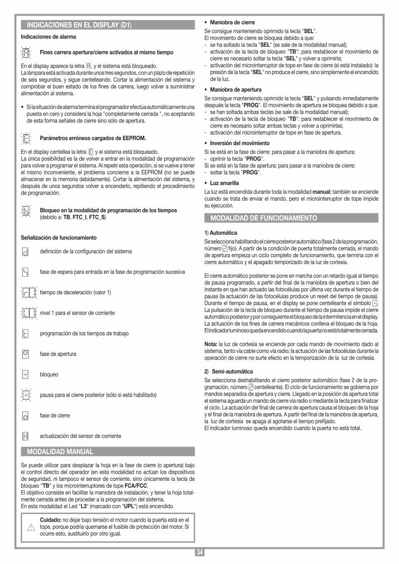
34
Indicaciones de alarma
Fines carrera apertura/cierre activados al mismo tiempo
En el display aparece la letra , y el sistema está bloqueado.La lámpara está activada durante unos tres segundos, con un plazo de repetición de seis segundos, y sigue centelleando. Cortar la alimentación del sistema y comprobar el buen estado de los fines de carrera, luego volver a suministrar alimentación al sistema.
• Si la situación de alarma termina el programador efectúa automáticamente una puesta en cero y considera la hoja "completamente cerrada ", no aceptando de esta forma señales de cierre sino sólo de apertura.
Parámetros erróneos cargados de EEPROM.
En el display centellea la letra y el sistema está bloqueado.La única posibilidad es la de volver a entrar en la modalidad de programación para volver a programar el sistema. Al repetir esta operación, si se vuelve a tener el mismo inconveniente, el problema concierne a la EEPROM (no se puede almacenar en la memoria debidamente). Cortar la alimentación del sistema, y después de unos segundos volver a encenderlo, repitiendo el procedimiento de programación.
Bloqueo en la modalidad de programación de los tiempos (debido a: TB, FTC_I, FTC_S)
Señalización de funcionamiento
definición de la configuración del sistema
fase de espera para entrada en la fase de programación sucesiva
tiempo de deceleración (valor 1)
nivel 1 para el sensor de corriente
programación de los tiempos de trabajo
fase de apertura
bloqueo
pausa para el cierre posterior (sólo si está habilitado)
fase de cierre
actualización del sensor de corriente
Se puede utilizar para desplazar la hoja en la fase de cierre (o apertura) bajo el control directo del operador (en esta modalidad no actúan los dispositivos de seguridad, ni tampoco el sensor de corriente, sino únicamente la tecla de bloqueo "TB" y los microinterruptores de tope FCA/FCC. El objetivo consiste en facilitar la maniobra de instalación, y tener la hoja total-mente cerrada antes de proceder a la programación del sistema.En esta modalidad el Led "L3" (marcado con "UPL") está encendido.
Cuidado: no dejar bajo tensión el motor cuando la puerta está en el tope, porque podría quemarse el fusible de protección del motor. Si ocurre esto, sustituirlo por otro igual.
• Maniobra de cierreSe consigue manteniendo oprimido la tecla "SEL".El movimiento de cierre se bloquea debido a que:- se ha soltado la tecla "SEL" (se sale de la modalidad manual);- activación de la tecla de bloqueo "TB": para restablecer el movimiento de
cierre es necesario soltar la tecla "SEL" y volver a oprimirla;- activación del microinterruptor de tope en fase de cierre (si está instalado): la
presión de la tecla "SEL" no produce el cierre, sino simplemente el encendido de la luz.
• Maniobra de aperturaSe consigue manteniendo oprimido la tecla "SEL" y pulsando inmediatamente después la tecla "PROG". El movimiento de apertura se bloquea debido a que:- se han soltada ambas teclas (se sale de la modalidad manual);- activación de la tecla de bloqueo "TB": para restablecer el movimiento de
cierre es necesario soltar ambas teclas y volver a oprimirlas;- activación del microinterruptor de tope en fase de apertura.
• Inversión del movimientoSi se está en la fase de cierre: para pasar a la maniobra de apertura: - oprimir la tecla "PROG".Si se está en la fase de apertura: para pasar a la maniobra de cierre: - soltar la tecla "PROG".
• Luz amarillaLa luz está encendida durante toda la modalidad manual; también se enciende cuando se trata de enviar el mando, pero el microinterruptor de tope impide su ejecución.
1) AutomáticaSe selecciona habilitando el cierre posterior automático (fase 2 de la programación, número fijo). A partir de la condición de puerta totalmente cerrada, el mando de apertura empieza un ciclo completo de funcionamiento, que termina con el cierre automático y el apagado temporizado de la luz de cortesía.
El cierre automático posterior se pone en marcha con un retardo igual al tiempo de pausa programado, a partir del final de la maniobra de apertura o bien del instante en que han actuado las fotocélulas por última vez durante el tiempo de pausa (la actuación de las fotocélulas produce un reset del tiempo de pausa).Durante el tiempo de pausa, en el display se pone centelleante el símbolo . La pulsación de la tecla de bloqueo durante el tiempo de pausa impide el cierre automático posterior y por consiguiente el bloqueo de la intermitencia en el display. La actuación de los fines de carrera mecánicos conlleva el bloqueo de la hoja.El indicador luminoso queda encendido cuando la puerta no está totalmente cerrada.
Nota: la luz de cortesía se enciende por cada mando de movimiento dado al sistema, tanto vía cable como vía radio; la actuación de las fotocélulas durante la operación de cierre no surte efecto en la temporización de la luz de cortesía.
2) Semi-automáticaSe selecciona deshabilitando el cierre posterior automático (fase 2 de la pro-gramación, número centelleante). El ciclo de funcionamiento se gobierna por mandos separados de apertura y cierre. Llegado en la posición de apertura total el sistema aguarda un mando de cierre vía radio o mediante la tecla para finalizar el ciclo. La actuación del final de carrera de apertura causa el bloqueo de la hoja y el final de la maniobra de apertura. A partir del final de la maniobra de apertura, la luz de cortesía se apaga al agotarse el tiempo prefijado.El indicador luminoso queda encendido cuando la puerta no está total.
INDICACIONES EN EL DISPLAY (D1)
MODALIDAD MANUAL
MODALIDAD DE FUNCIONAMIENTO
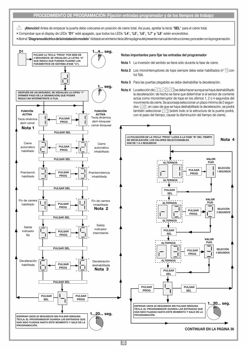
35
Tecla dinámicaabrir-cerrar
PULSARPROG
Tecla dinámica abrir-bloquear
cerrar-bloquear
Cierreautomáticohabilitado
Cierreautomáticoinhabilitado
PULSAR SEL
PULSARPROG
PULSAR SEL
FUNCIÓNACTIVA
Preintermit.habilitado
PULSARPROG
Preintermitenciainhabilitada
Salidaindicador
fijo
Deceleraciónhabilitada PULSAR
PROG
Deceleracióndeshabilitada
D1PULSAR LA TECLA "PROG" POR MÁS DE4 SEGUNDOS: SE VISUALIZA LA LETRA "d"QUE INDICA QUE PUEDEN FIJARSE LOSPARÁMETROS DE SISTEMA (FASE "A").
1...4... seg.
1... seg.
FUNCIÓNACTIVA
PULSARSEL
1...20... seg.
DESPUÉS DE UN SEGUNDO, SE VISUALIZA LA CIFRA "1" (PRIMER PASO DE LA GRAMACIÓN) QUE PODRÁ RESULTAR INTERMITENTE O FIJA.
Nota 1
PULSAR SEL
PULSAR PROG
Fin de carrerahabilitado
ESPERAR UNOS 20 SEGUNDOS SIN PULSAR NINGUNA TECLA: EL PROGRAMADOR GUARDA LAS ENTRADAS QUE HAN SIDO FIJADAS HASTA ESTE MOMENTO Y SALE DE LA PROGRAMACIÓN.
PULSAR SEL
ALTERNOS
ALTERNOS
PULSARSEL
PULSARPROG
ALTERNOS
ALTERNOS
PULSAR PROG
VALORFIJO
PULSAR SEL
ALTERNOS
ALTERNOS
PULSAR PROG
VALORFIJO
VALORFIJO
LA PULSACIÓN DE LA TECLA "PROG" LLEVA A LA FASE "B" DEL TIEMPO DE DECELEACIÓN. LOS VALORES SELECCIONABLESVAN DE 1 A 4 SEGUNDOS
PULSARPROG
PULSAR SEL
1...20... seg.ESPERAR UNOS 20 SEGUNDOS SIN PULSAR NINGUNA TECLA: EL PROGRAMADOR GUARDA LAS ENTRADAS QUE HAN SIDO FIJADAS HASTA ESTE MOMENTO Y SALE DE LA PROGRAMACIÓN.
PULSARSEL
PULSARPROG
Salidaindicador
intermitente
SELECCIÓN1 SEGUNDOS
SELECCIÓN2 SEGUNDOS
SELECCIÓN4 SEGUNDOS
PULSAR SEL
PULSARPROG
PULSAR SEL
Nota 2
Fin de carrerainhabilitado
Nota 3
Nota 4
¡Atención! Antes de empezar la puerta debe colocarse en posición de cierre total. Así pues, apretar la tecla "SEL" para el cierre total.• Comprobar que el display de LEDs "D1" esté apagado, que todos los LEDs "L4", "L5", "L6", "L7" y "L8" estén encendidos.• Abrir el "Diagrama eléctrico de la instalación modelo" doblado en el interior de la última página del presente manual de instrucciones y proceder con la programación.
PROCEDIMIENTO DE PROGRAMACIÓN (Fijación entradas programador y de los tiempos de trabajo)
Notas importantes para fijar las entradas del programador
Nota 1 La inversión del sentido se tiene sólo durante la fase de cierre.
Nota 2 Los microinterruptores de tope siempre debe estar habilitados (n° con luz fija).
Nota 3 Para las puertas plegables se debe deshabilitar la deceleración.
Nota 4 La selección de , , se debe hacer aunque se haya deshabilitado la deceleración: de hecho se tiene que determinar si el sensor de corriente actúa como microinterruptor de tope en los últimos 1, 2 o 4 segundos del movimiento de cierre. Se aconseja seleccionar un plazo mínimo de 2 segun-dos ; en caso de que se haya deshabilitado la deceleración, se podrá también seleccionar (sobre todo si la estructura de la puerta podrá, con el paso del tiempo, causar la disminución del tiempo de cierre).
CONTINUAR EN LA PÁGINA 36
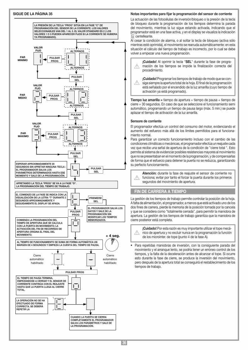
36
PULSAR SEL
ALTERNOS
ALTERNOS
ALTERNOS
ALTERNOS
PULSAR SEL
ALTERNOS
ALTERNOS
PULSAR SEL
ESPERAR APROXIMADAMENTE 20 SEGUNDOS SIN APRETAR NINGUNA TECLA : EL PROGRAMADOR SALVA LOS PARÁMETROS DETERMINADOS HASTA ESE MOMENTO Y SALE DE LA PROGRAMACIÓN.
PULSAR SEL
APRETANDO LA TECLA "PROG" SE VA A LA FASE "D".LA PROGRAMACIÓN DEL TIEMPO DE TRABAJO.
PULSAR PROG
EL COMIENZO DE LA FASE SE INDICA CON LA VISUALIZACIÓN DE LA LETRA "T" DURANTE 2 SEGUNDOS APROXIMADAMENTE Y SEGUIDAMENTE EL DISPLAY SE APAGA.
COMIENZA LA PROGRAMACIÓN DEL TIEMPO DE APERTURA QUE SE CALCULA CON LA PUERTA EN MOVIMIENTO; LA ACTIVACIÓN DEL FIN DE RECORRIDO DE APERTURA ORIGINA EL FINAL DEL MOVIMIENTO.
AL TIEMPO DE FUNCIONAMIENTO SE SUMA DE FORMA AUTOMÁTICA UN MÁRGEN DE 4 SEGUNDOS Y EMPIEZA LA CUENTA DEL TIEMPO DE PAUSA.
Cierreautomático habilitado
Cierreautomático habilitado
PULSAR PROG
+ 4 seg.
EL TIEMPO DE PAUSA TERMINA, EMPEZÁNDOSE A CERRAR Y EL SENSOR DE CORRIENTE CONTINÚA CON EL REAJUSTE HASTA QUE LA PUERTA LLEGA AL CIERRE TOTAL.
LA OPERACIÓN NO SE HA EFECTUADO DE FORMA CORRECTA. SE DEBERÁ REPETIR LA
CUANDO LA PUERTA SE CIERRA COMPLETAMENTE EL PROGRAMADOR SALVA LOS PARÁMETROS Y SALE DE LA PROGRAMACIÓN.
LA PRESIÓN DE LA TECLA "PROG" SITÚA EN LA FASE "C" DE PROGRAMACIÓN DEL SENSOR DE LA CORRIENTE. LOS VALORES SELECCIONABLES VAN DEL 1 AL 3. EL VALOR STANDARD ES 2 ( LOS VALORES 1 O 3 PUEDEN APARECER FIJOS SI LA CORRIENTE SE HUBIERA YA PROGRAMADO).
PREMERE SEL
EL PROGRAMADOR SALVA LOS DATOS Y SALE DE LA PROGRAMACIÓN SIN MODIFICAR LOS TIEMPOS MEMORIZADOS.
PULSAR PROG
PULSAR PROG
VALORFIJO
PULSAR PROG
VALORFIJO
VALORFIJO
PARMINIMO
PARMEDIO
PARMÁXIMO
Notas importantes para fijar la programación del sensor de corrienteLa actuación de las fotocélulas de inversión/bloqueo o la presión de la tecla de bloqueo durante la programación de los tiempos determina la parada del movimiento, mientras la luz sigue estando activada, indicando que el programador está en una fase activa, y en el display se visualiza la indicación
centelleante.Al cesar la condición de alarma, o al soltar la tecla de bloqueo (activa sólo mientras esté oprimida), el movimiento se reanuda automáticamente: en esta situación el cálculo del tiempo de trabajo es incorrecto, por lo cual se debe volver a empezar una nueva programación.
¡Cuidado! Al oprimir la tecla "SEL" durante la fase de progra-mación de los tiempos se impide la finalización correcta del procedimiento. ¡Cuidado! Programar los tiempos de trabajo de modo que se con-siga siempre la apertura total de la hoja. El final de la programación está señalado por el encendido de la luz amarilla (cuyo tiempo de activación ya está programado).
Tiempo luz amarilla = tiempo de apertura + tiempo de pausa + tiempo de cierre + 30 segundos. En caso de que se seleccione el funcionamiento semi automático, programando un tiempo de pausa largo (máx. 5 min.) se puede aplazar el tiempo de activación de la luz amarilla.
Sensore de corrienteEl programador efectúa un control del consumo del motor, evidenciando el aumento del esfuerzo más allá de los límites permitidos para el funciona-miento normal.Para garantizar un correcto funcionamiento incluso con el cambio de las condiciones climáticas o mecánicas, el programador efectúa un reajuste cada vez que recibe una señal de apertura de la condición de "cierre total ". Esto permite al sistema de evidenciar posibles resistencias mayores al movimiento que no se presentaban en el momento de la programación, y de compensarlas de forma que el esfuerzo para detener la puerta no se reduzca, garantizando su perfecto funcionamiento.
Atención: durante la fase de reajuste el sensor de corriente no funciona; evitar por tanto el forzar la puerta durante los primeros segundos del movimiento de apertura.
La gestión de los tiempos de trabajo permite controlar la posición de la hoja. A falta de alimentación, el programador, a menos que esté activado uno de los dos fines de carrera, pierde la memoria de la posición tomada por la cancela y que se considera como "totalmente cerrada", para permitir la maniobra de apertura. La gestión de los tiempos de trabajo garantiza que la maniobra de cierre posterior está completa.
¡Cuidado! Por esta razón es muy importante utilizar el tope mecá-nico de apertura y no excluir nunca en la programación la función de los microinter. de tope (punto 4 de la fase A).
• Para repetidas maniobras de inversión, con la consiguiente parada del movimiento y el arranque lento, se podría tener un erróneo control de los tiempos, y la falta de la deceleración antes de alcanzar el tope. Si ocurre esto durante la fase de cierre, se produce la inversión del movimiento, pero después de la apertura total se conseguirá el restablecimiento de los tiempos de trabajo.
FIN DE CARRERA A TIEMPO
SIGUE DE LA PÁGINA 35

37
Es posible accionar a distancia el motor mediante el control remoto: está dispo-nible una sola función (mando secuencial de "apertura-bloqueo-cierre-bloqueo"), ejecutable indistintamente con uno cualquiera de los canales disponibles.Por esta razón para cada emisor habilitado para el mando será suficiente memo-rizar uno solo de los canales disponibles.
RADIOMANDO SERIE S449Módulo de memoriaExtraíble, dotado de memoria no volátil de tipo EEPROM, lleva los códigos (300 teclas de canales). Los códigos permanecen en el módulo de memoria incluso a falta de fluido eléctrico.
¡Cuidado! Antes de proceder a la primera memorización, hace falta borrar totalmente la memoria. Al tener que sustituir la tarjeta electró-nica debido a alguna avería, el módulo de memoria se puede sacar e introducir en la nueva tarjeta cuidando su orientación según lo que está indicado en la fig. 9, det.A.
Indicaciones Led piloto "L2" (fig. 9)Led piloto centelleante rápidamente: borrado de un código Led piloto centelleante lentamente: almacenamiento de un códigoLed piloto fija: memoria enteramente ocupada.
GESTION DE LOS CODIGOS DE LOS EMISORESA. Almacenamiento de un canal (mediante el emisor acoplado)B. Borrado de un canal (mediante el emisor acoplado)C. Borrado total de la memoria de códigosD. Memorización de otros canales vía radio (sin abrir el contenedor donde está alojada la centralita).
A) Almacenamiento de un canal (fig. 9):1. Presionar la tecla "P3" MEMO y mantenerla pulsada: el Led "L2" se pone a
centellear lentamente.2. Activar simultáneamente el emisor en el canal a memorizar.3. Mantener presionada la tecla "P3" MEMO hasta que el Led "L2" vuelve a estar
centelleante.4. Soltar la tecla "MEMO": el Led sigue centelleando.5. Activar por segunda vez el emisor (mismo emisor, mismo canal; si el canal es
diferente o bien se trata de otro emisor, el almacenamiento acaba sin éxito).6. Fin del almacenamiento: el Led "L2" queda encendido durante 2 segundos,
indicando que el almacenamiento es correcto.
Notas: No es posible almacenar en la memoria un usuario que ya está en la memoria: en este caso durante la activación del radiomando (punto 2) se inte-rrumpe la luz centelleante del Led. Sólo después de soltar la tecla "P3" MEMO será posible reanudar el procedimiento de memorización.Si después de la primera activación del radiomando no se lo vuelve a activar, después de 15 segundos se sale automáticamente de la modalidad de almace-namiento sin almacenar en la memoria el nuevo código del usuario.
B) Borrado de un canal (fig. 9)1. Presionar la tecla "P4" DEL y mantenerla pulsada: el Led "L2" empieza a
centellear rápidamente.2. Activar el emisor en el canal a borrar.3. El Led queda encendido durante 2 segundos, indicando que se ha realizado
el borrado.
Notas: si el usuario que se quiere borrar no está almacenado en la memoria, el Led deja de centellear; será posible reanudar el procedimiento de borrado sólo después de soltar la tecla "P4". Tanto para el procedimiento de almacenamiento como de borrado, si se suelta la tecla antes de la activación del radiomando, se sale inmediatamente de la modalidad.
C - Borrado total de la memoria de usuarios (fig. 9)1. Mantener pulsadas ambas teclas ("P3+P4") durante algo más de 4 segundos.2. El Led "L2" se queda encendido durante todo el tiempo de borrado (8 segundos
aproximadamente).3. El Led "L2" se apaga: el borrado ha terminado.
Notas: Cuando la memoria del receptor está a punto de agotarse, la búsqueda del usuario puede durar 1 segundo como máximo después de recibir el mando radio. Si el Led "L2" está siempre encendido, la memoria está enteramente ocupada. Para almacenar un nuevo TX hace falta borrar un código de la memoria.
D - Memorización de otros canales vía radio• La memorización se puede activar también vía radio (sin abrir el contenedor
donde está alojada la centralita) si el jumper "J1" está inserido (fig. 9).1. Comprobar que el jumper "J1" está conectado (fig. 9).2. Utilizando un radiomando donde al menos una
de las teclas de canal "A-B-C-D" ya está memo-rizada en el receptor, activar la tecla dentro del radiomando según lo que está representado en la figura.
Nota: todos los receptores alcanzables por la emisión del radiomando, y que tengan al menos un canal del emisor memorizado, activarán al mismo tiempo el avisador acústico "B1" (fig. 9).
3. Para seleccionar el receptor donde memorizar el nuevo código, activar una de las teclas de canal del mismo emisor. Los receptores que no tienen el código de esa tecla se desactivarán con la emisión de un "Toque" de 5 segundos de duración; en cambio el que tiene el código emitirá otro "Toque" de un segundo de duración, entrando efectivamente en la modalidad de memorización "vía radio".
4. Presionar la tecla de canal seleccionada con anterioridad en el emisor a memorizar; realizada la memorización, el receptor emitirá 2 "Toques" de medio segundo, después de lo cual estará listo para memorizar otro código.
5. Para salir de esta modalidad, dejar pasar "3" segundos sin memorizar códigos. El receptor emitirá un "Toque" de 5 segundos y saldrá de la modalidad.
• Cuando la memoria estará totalmente ocupada, el avisador acústico emitirá diez "Toques" muy próximos saliendo automáticamente de la modalidad de memorización "vía radio" y el Led "L2" quedará encendido; la misma indi-cación se consigue también: cada vez que se intenta entrar en la modalidad "vía radio" con la memoria totalmente ocupada.
CONEXION DE LA ANTENA PARA MODULO RF DE 433,92 MHzEl receptor está dotado de antena propia, que consta de un trozo de hilo rígido, de 170 mm. de largo. En alternativa es posible utilizar una antena acordada ANS400 a conectar al receptor mediante un cable coaxial RG58 (impedancia 50Ω) de 15 m de largo como máximo.
MEMORIZZAZIONE CODICE TX-RX
RCQ449100
13-04-2001
DM0531 Description :
Product Code :
Date :
Drawing number :
P.J.Heath
CARDIN ELETTRONICA S.p.A - 31020 San Vendemiano (TV) Italy - via Raffaello, 36 Tel: 0438/401818 Fax: 0438/401831
Draft :
All rights reserved. Unauthorised copying or use of the information contained in this document is punishable by law
MR
MANDO VÍA RADIO
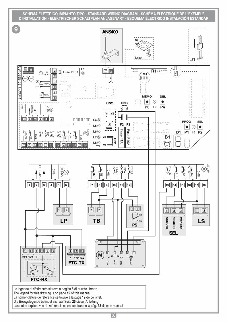
38
Collegamenti scheda base per S449
PRG850
02-09-2002
DI0253
PRG850BX3 (memo radio)
P2
1 2
P1
SEL
Fuse T1.6A
Fuse F1A
CS
1038B.03 D
C0341
Fuse F10A
PROG
P4P3
DELMEMO
L2
L3
L1
L5
L6
L7
L8
L4
D1
CN3CN2
CN1
F1
F3F2
V1 V2
V0
R1
V3
V4
1 2 3 4 5 6
7 8 9 10 13 14 15 1611 12 17 18
2423
2221
2019
26 25
trf 230V~
line 230V~
LC 230V~
NL
27 28
V3
V4
M1
S449
24C16A)
B1
1 2
LP
1 2
LS
SEL
1 32
CLO
SIN
G
CO
MM
ON
OP
EN
ING
TD TB
LS 24V
~
FCC
FCA
FTC_I
FTC_S TC
TA TAL
LP 24V
~
OU
T 24V~
CM
N
1 2
TB
24V 12V 0
C
1 65432
NA
NC NC
CNA
FTC-RX
1 32
24V12V0
FTC-TX
1 2
PS
NC
NA
J1
J1
Description:
Product Code :
Date :
Drawing number :
P.J.Heath
CARDIN ELETTRONICA S.p.A - 31020 San Vendemiano (TV) Italy - via Raffaello, 36 Tel: 0438/401818 Fax: 0438/401831
Draft :
All rights reserved. Unauthorised copying or use of the information contained in this document is punishable by law
7 8 9 10 13 14 15 1611 12 17 18
TD TB
LS 24V
~
FCC
FCA
FTC_I
FTC_S TC
TA TAL
CM
N
1 2 3 4 5 6
LP 24V
~
OU
T 24V~
CM
N
CM
N
CM
N
CM
N
ANS400
5
M
24V
dc
FCA
4
FCC
3 2
CO
M.
1M
SCHEMA ELETTRICO IMPIANTO TIPO - STANDARD WIRING DIAGRAM - SCHÉMA ÉLECTRIQUE DE L'EXEMPLED'INSTALLATION - ELEKTRISCHER SCHALTPLAN ANLAGENART - ESQUEMA ELECTRICO INSTALACIÓN ESTANDAR
9
La legenda di riferimento si trova a pagina 5 di questo librettoThe legend for this drawing is on page 12 of this manualLa nomenclature de référence se trouve à la page 19 de ce livret.Die Bezugslegende befindet sich auf Seite 26 dieser AnleitungLas notas explicativas de referencia se encuentran en la pág. 33 de este manual
39
The CE conformity declaration for Cardin products is available in original language from the site www.cardin.it under the section "Standards and Certification".Les déclarations de conformité CE des produits Cardin sont disponibles dans la langue originale sur le site www.cardin.it dans la section "normes et certificats".Die CE-Konformitätserklärungen für die Cardin-Produkte stehen in der Originalsprache auf der Homepage www.cardin.it im Bereich "Normen und Zertifizierung" zur Verfügung.Las declaraciones de conformidad CE de los productos Cardin se encuentran disponibles en el idioma original en el sitio www.cardin.it en la sección "normas y certificaciones".
CARDIN ELETTRONICA spa Via Raffaello, 36- 31020 San Vendemiano (TV) ItalyTel: +39/0438.404011-401818Fax: +39/0438.401831email (Italy): [email protected] (Europe): [email protected]: www.cardin.it
GL 24 Vdc 04-07-2002DCE014
Il costruttore: CARDIN ELETTRONICA S.p.A. DICHIARA CHE L'APPARECCHIATURA DESTINATA AD ESSERE INSERITA IN MACCHINE E NON FUNZIONANTE IN MODO INDIPENDENTE:
Nome dell'apparato Motoriduttore GL1124Tipo di apparato Automazione a 24 Vdc per porte sezionali e basculantiModello GL1124 - GL112400 - GL112401 - GL112402 - GL112409Marchio Cardin ElettronicaAnno di prima fabbricazione 2002
e sono state applicate le seguenti norme e/o specifiche tecniche:- EN 50081-1 : 1992- EN 50082-1 : 1992- EN 55022 : 1994- EN 55014 : 1993- ETS 300683 : 1997- EN 60335-1 : 1994 (e aggiornamenti successivi)
è ideata per essere incorporata in una macchina o per essere assemblato con altri macchinari per costituire una macchina considerata dalla Direttiva 89/392/CEE e successivi emendamenti.
è conforme alle disposizioni delle seguenti direttive comunitarie:- Direttiva 2004/108/CE (Compatibilità Elettromagnetica)- Direttiva 2006/95/CE (Direttiva Bassa Tensione)- Direttiva 99/05/CE (R&TTE)
x x x x x x x x x x x x x x x x x x x x x x x x x x x x x x x x x x x x x x x x x x x x x x x x x x x x x x x x x x
x x x x x x x x x x x x x x x x x x x x x x x x x x x x x x x x x x x x x x x x x x x x x x x x x x x x x x x x x x
x x x x x x x x x x x x x x x x x x x x x x x x x x x x x x x x x x x x x x x x x x x x x x x x x x x x x x x x x x
x x x x x x x x x x x x x x x x x x x x x x x x x x x x x x x x x x x x x x x x x x x x x x x x x x x x x x x x x x
x x x x x x x x x x x x x x x x x x x x x x x x x x x x x x x x x x x x x x x x x x x x x x x x x x x x x x x x x x
x x x x x x x x x x x x x x x x x x x x x x x x x x x x x x x x x x x x x x x x x x x x x x x x x x x x x x x x x
x x x x x x x x x x x x x x x x x x x x x x x x x x x x x x x x x x x x x x x x x x x x x x x x x x x x x x x x x x
x x x x x x x x x x x x x x x x x x x x x x x x x x x x x x x x x x x x x x x x x x x x x x x x x x x x x x x x x
x x x x x x x x x x x x x x x x x x x x x x x x x x x x x x x x x x x x x x x x x x x x x x x x x x x x x x x x x x
Dichiarazione di Conformità CE(Direttiva Macchine 89/392/CEE, All. II)
MODELLO DATACODICE SERIE
Il costruttore è in possesso dei seguenti certificati di conformità CE rilasciate dal "Competent Body" PRIMA RICERCA & SVILUPPO e delle relazioni di prova rilasciate da Nemko Alflab:- relazione di prova EMC 2554/98 (08.01.1999)- relazione di prova EMC.TR.99.146 (21/12/99) - certificato di conformità CE n. 99.123- relazione di prova SAF.TR.99.234 (20/09/99) - certificato di conformità CE n. 99.226
INOLTRE DICHIARA CHE NON È CONSENTITO METTERE IN SERVIZIO L' APPARECCHIATURA FINO A CHE LA MACCHINA NELLA QUALE SARÀ INCORPORATA E DELLA QUALE DIVENTERÀ COMPONENTE SIA STATA IDENTIFICATA E NE SIA STATA DICHIARATA LA CONFORMITÀ ALLE DISPOSIZIONI DELLA DIRETTIVA 89/392/CEE E SUCCESSIVI EMENDAMENTI.
San Vendemiano il 30/03/2012 Ing. A. Fiorotto
Responsabile Tecnico - R&D Laboratory
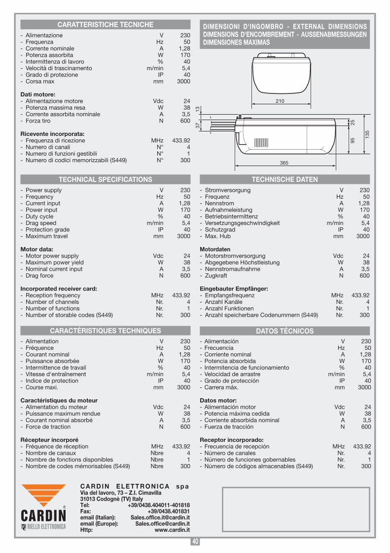
40
CARACTÉRISTIQUES TECHNIQUES DATOS TÉCNICOS
TECHNICAL SPECIFICATIONS TECHNISCHE DATEN
CARATTERISTICHE TECNICHE- Alimentazione V 230 - Frequenza Hz 50- Corrente nominale A 1,28- Potenza assorbita W 170- Intermittenza di lavoro % 40- Velocità di trascinamento m/min 5,4- Grado di protezione IP 40- Corsa max mm 3000
Dati motore:- Alimentazione motore Vdc 24- Potenza massima resa W 38- Corrente assorbita nominale A 3,5- Forza tiro N 600
Ricevente incorporata:- Frequenza di ricezione MHz 433.92- Numero di canali N° 4- Numero di funzioni gestibili N° 1- Numero di codici memorizzabili (S449) N° 300
- Power supply V 230 - Frequency Hz 50- Current input A 1,28- Power input W 170- Duty cycle % 40- Drag speed m/min 5,4- Protection grade IP 40- Maximum travel mm 3000
Motor data:- Motor power supply Vdc 24- Maximum power yield W 38- Nominal current input A 3,5- Drag force N 600
Incorporated receiver card:- Reception frequency MHz 433.92- Number of channels Nr. 4- Number of functions Nr. 1- Number of storable codes (S449) Nr. 300
- Alimentation V 230 - Fréquence Hz 50- Courant nominal A 1,28- Puissance absorbée W 170- Intermittence de travail % 40- Vitesse d'entraînement m/min 5,4- Indice de protection IP 40- Course maxi. mm 3000 Caractéristiques du moteur- Alimentation du moteur Vdc 24- Puissance maximum rendue W 38- Courant nominal absorbé A 3,5- Force de traction N 600
Récepteur incorporé- Fréquence de réception MHz 433.92- Nombre de canaux Nbre 4- Nombre de fonctions disponibles Nbre 1- Nombre de codes mémorisables (S449) Nbre 300
- Stromversorgung V 230 - Frequenz Hz 50- Nennstrom A 1,28- Aufnahmeleistung W 170- Betriebsintermittenz % 40- Versetzungsgeschwindigkeit m/min 5,4- Schutzgrad IP 40- Max. Hub mm 3000 Motordaten- Motorstromversorgung Vdc 24- Abgegebene Höchstleistung W 38- Nennstromaufnahme A 3,5- Zugkraft N 600
Eingebauter Empfänger:- Empfangsfrequenz MHz 433.92- Anzahl Kanäle Nr. 4- Anzahl Funktionen Nr. 1- Anzahl speicherbare Codenummern (S449) Nr. 300
SCALA: 1:2
Prodotti Technocity
GL1024
25-05-98
DI0064 Description :
Product Code :
Date :
Drawing number :
P.J.Heath
CARDIN ELETTRONICA S.p.A - 31020 San Vendemiano (TV) Italy - via Raffaello, 36 Tel: 0438/401818 Fax: 0438/401831
Draft :
All rights reserved. Unauthorised copying or use of the information contained in this document is punishable by law
INGOMBRO GL1024
210 365
135
2595
3713
- Alimentación V 230 - Frecuencia Hz 50 - Corriente nominal A 1,28- Potencia absorbida W 170- Intermitencia de funcionamiento % 40- Velocidad de arrastre m/min 5,4- Grado de protección IP 40- Carrera máx. mm 3000
Datos motor:- Alimentación motor Vdc 24- Potencia máxima cedida W 38- Corriente absorbida nominal A 3,5- Fuerza de tracción N 600
Receptor incorporado:- Frecuencia de recepción MHz 433.92- Número de canales Nr. 4- Número de funciones gobernables Nr. 1- Número de códigos almacenables (S449) Nr. 300
SCALA: 1:2
Prodotti Technocity
GL1024
25-05-98
DI0064 Description :
Product Code :
Date :
Drawing number :
P.J.Heath
CARDIN ELETTRONICA S.p.A - 31020 San Vendemiano (TV) Italy - via Raffaello, 36 Tel: 0438/401818 Fax: 0438/401831
Draft :
All rights reserved. Unauthorised copying or use of the information contained in this document is punishable by law
INGOMBRO GL1024
210 365
135
2595
3713
DIMENSIONI D'INGOMBRO - EXTERNAL DIMENSIONS DIMENSIONS D'ENCOMBREMENT - AUSSENABMESSUNGEN DIMENSIONES MAXIMAS
C A R D I N E L E T T R O N I C A s p a Via del lavoro, 73 – Z.I. Cimavilla 31013 Codognè (TV) ItalyTel: +39/0438.404011-401818Fax: +39/0438.401831email (Italian): [email protected] (Europe): [email protected]: www.cardin.it