30+30 band control60 digital equalizer - alto professional · 2020-02-05 · band pass filters high...
TRANSCRIPT

CONTROL6030+30 Band
Digital Equalizer
User's Manual
NF01202-2.3
LTOR
www.altoproaudio.com
Version 2.3 September 2005
English
No. 1, Lane 17, Sec. 2, Han Shi West Road, Taichung 40151 Taiwanhttp://www.altoproaudio.com Tel: 886-4-22313737
email: [email protected] Fax: 886-4-22346757
c
All rights reserved to ALTO. All features and content might be changedwithout prior notice. Any photocopy, translation, or reproduction of part of this
manual without written permission is forbidden. Copyright 2005 SEIKAKU GROUP
SE KAKU TECHNICAL GROUP LIMITEDI

7. WARRANTY
1. WARRANTY REGISTRATION CARD
To obtain Warranty Service, the buyer should first fill out and return the enclosed Warranty Registration Card within
10 days of the Purchase Date.
All the information presented in this Warranty Registration Card gives the manufacturer a better understanding of
the sales status, so as to purport a more effective and efficient after-sales warranty service.
Please fill out all the information carefully and genuinely, miswriting or absence of this card will void your warranty
service.
2. RETURN NOTICE
2.1 In case of return for any warranty service, please make sure that the product is well packed in its original shipping
carton, and it can protect your unit from any other extra damage.
2.2 Please provide a copy of your sales receipt or other proof of purchase with the returned machine, and give detail
information about your return address and contact telephone number.
2.3 A brief description of the defect will be appreciated.
2.4 Please prepay all the costs involved in the return shipping, handling and insurance.
3. TERMS AND CONDITIONS
3.1 warrants that this product will be free from any defects in materials and/or workmanship for a periodLTO
of 1 year from the purchase date if you have completed the Warranty Registration Card in time.
3.3 During the warranty service, may repair or replace this product at its own option at no charge to you forLTO
parts or for labor in accordance with the right side of this limited warranty.
3.4 This warranty does not apply to the damages to this product that occurred as the following conditions:
Normal tear and wear.
Instead of operating in accordance with the user's manual thoroughly, any abuse or misuse of this product.
The product has been altered or modified in any way.
Damage which may have been caused either directly or indirectly by another product / force / etc.
Abnormal service or repairing by anyone other than the qualified personnel or technician.
And in such cases, all the expenses will be charged to the buyer.
3.5 In no event shall be liable for any incidental or consequential damages. Some states do not allow the exclu-LTO
sion or limitation of incidental or consequential damages, so the above exclusion or limitation may not apply to you.
3.6 This warranty gives you the specific rights, and these rights are compatible with the state laws, you may also
have other statutory rights that may vary from state to state.
3.2 The warranty service is only available to the original consumer, who purchased this product directly from the
retail dealer, and it can not be transferred.
16
SAFETY RELATED SYMBOLS
CAUTION
RISK OF ELECTRIC SHOCKDO NOT OPEN
This symbol, wherever used, alerts you to the pre-
sence of un-insulated and dangerous voltages with-
in the product enclosure. These are voltages that
may be sufficient to constitute the risk of electric
shock or death.
Protective Ground Terminal
AC mains (Alternating Current)
Hazardous Live Terminal
ON: Denotes the product is turned on.
This symbol, wherever used, alerts you to impo-
rtant operating and maintenance instructions.
Please read.
OFF: Denotes the product is turned off.
WARNING
Describes precautions that should be observed to
prevent the possibility of death or injury to the user.
CAUTION
Describes precautions that should be observed to
prevent damage to the product.
Protective Ground
Operating Conditions
IMPORTANT SAFETY INSTRUCTIONS
Cleaning
Servicing
Power Cord and Plug
the recommended fuse type as indicated in this
manual. Do not short-circuit the fuse holder. Before
replacing the fuse, make sure that the product is
OFF and disconnected from the AC outlet.
Before turning the product ON, make sure that it is
connected to Ground. This is to prevent the risk of
electric shock.
Never cut internal or external Ground wires. Likewise,
never remove Ground wiring from the Protective
Ground Terminal.
Always install in accordance with the manufacturer's
instructions.
To avoid the risk of electric shock and damage, do
not subject this product to any liquid/rain or moisture.
Do not use this product when in close proximity to
water.
Do not install this product near any direct heat source.
Do not block areas of ventilation. Failure to do so
could result in fire.
Keep product away from naked flames.
Read these instructions
Follow all instructions
Keep these instructions. Do not discard.
Heed all warnings.
Only use attachments/accessories specified by the
manufacturer.
Do not tamper with the power cord or plug. These are
designed for your safety.
Do not remove Ground connections!
If the plug does not fit your AC outlet seek advice from
a qualified electrician.
Protect the power cord and plug from any physical
stress to avoid risk of electric shock.
Do not place heavy objects on the power cord. This
could cause electric shock or fire.
When required, either blow off dust from the product
or use a dry cloth.
Do not use any solvents such as Benzol or Alcohol.
For safety, keep product clean and free from dust.
Refer all servicing to qualified service personnel only.
Do not perform any servicing other than those instruc-
tions contained within the User's Manual.
Fuse
To prevent fire and damage to the product, use only
No user serviceable parts inside.
Power Supply
Ensure that the mains source voltage (AC outlet)
matches the voltage rating of the product. Failure
to do so could result in damage to the product and
possibly the user.
Unplug the product before electrical storms occur
and when unused for long periods of time to reduce
the risk of electric shock or fire.
External Connection
Always use proper ready-made insulated mains
cabling (power cord). Failure to do so could result
in shock/death or fire. If in doubt, seek advice from
a registered electrician.
Do Not Remove Any Covers
Within the product are areas where high voltages
may present. To reduce the risk of electric shock do
not remove any covers unless the AC mains power
cord is removed.
Covers should be removed by qualified service
personnel only.
WARNING
1
Disposing of this product should not be
placed in municipal waste and should be
Separate collection.

Band Pass Filters High pass Butterworth
Low pass Butterworth
Freq
Freq
20Hz 20KHz step 1/12 oct
Slope
Slope
AUX Section Delay line Up to 512 ms min step 21us
Digital input gain /+12dB step 0.5dB
Digital output volume /+12dB step 0.5dB
Analog Input Section Inputs 2 XLR F electronically balanced
Input Impedance >40 KohmsMax. Input Level
2 XLR M electronically balanced
<200 Ohms
+12dBv
20Hz 20KHz
>99 dB
0.01 1KHz 3 dBFSSampling Frequency
Conversion Input 20 bits Sigma-Delta
Conversion Output 24 bits Sigma-Delta
Analog Output Section Outputs
Output Impedance
Max. Output Level
Digital/Analog Interface Amplitude Response
Signal to Noise Ratio
THD+N
46.875 KHz
+12dBv
Memory Factory preset 36 (6 for each EQ type)
User preset 63
MIDI Section Connections Input/output/thru
Sockets 5 poles DIN(female)
mode PhotocoupledPower Supply Connector type 3 pole IEC, grounded
Type Servo controlled, switching
AC Input 95 240V~60 50Hz
Rated power consumption 15W
fuse 210 240V: T250mAL 250VAC95 120V: 500mAL 250VAC
User Interface Graphic Display 128 64 dotKeyboard 14 user keys/8 LEDsVu meter 2 6 LEDs
Physical Size Standard 19"rack mounting
Dimensions 483(W) 232.5(D) 44(H)mm(19" 9.3" 1.7")weight 3.5Kg(7.72lb)
6.TECHNICAL SPECIFICATIONS
Parametric Filters Gain /+15dB step 0.5dB
Freq 20Hz 20KHz step 1/12 oct
Bandwidth 0.05oct 3oct step 0.05oct
Bypass, 1 ord ( 6dB/oct), 2 ord ( 12dB/oct)st nd
20Hz 20KHz Step 1/12 oct
Bypass, 1 ord ( 6dB/oct), 2 ord ( 12dB/octstnd
15
Dear Customer:
PREFACE
Thanks for choosing LTO CONTROL60 and thanks for choosing one of the results of LTO AUDIO TEAM job and
researches.
For our LTO AUDIO TEAM, music and sound are more than a job...are first of all passion and let us say our
obsession!
We have been designing professional audio products for a long time in cooperation with some of the major brands
in the world in the audio field.
The LTO line presents unparalleled analogue and digital products made by Musicians for Musicians in our R&D
centers in Italy, Netherlands, United Kingdom and Taiwan. The core of our digital audio products is a sophisticated
DSP (Digital Sound Processor) and a large range of state of the art algorithms which have been developed by our
Software Team for the last 7 years.
Because we are convinced you are the most important member of LTO AUDIO TEAM and the one confirming the
quality of our job, we would like to share with you our work and our dreams, paying attention to your suggestions
and your comments.
Following this idea we create our products and we will create the new ones! From our side, we guarantee you and
we will guarantee you also in future the best quality, the best fruits of our continuous researches and the best prices.
Our LTO CONTROL60 is the result of many hours of listening and tests involving common people, area experts,
musicians and technicians.
The result of this effort is a DSP hi-performance equalizer that can be used in applications as musical performances,
installation and sound reinforcement.
Besides we offer to you a number of factory EQ curves that we collected and transformed in presets now available
in our small, efficient and easy to use LTO CONTROL60.
Nothing else to add, but that we would like to thank all the people that made the LTO CONTROL60 a reality available
to our customers, and thank our designers and all the LTO staff, people who make possible the realization of products
containing our idea of music and sound and are ready to support you, our customers, in the best way, conscious
that you are our best richness.
Thank you very much
LTO AUDIO TEAM
2
14
TABLE OF CONTENTS
1. INTRODUCTION .......................................................................................... ..................................4........
2. FEATURE LIST ......................................................................................................................................4
3. CONTROL ELEMENTS ............................................................................. .............................................4
3.1 The Front Panel
3.2 The Rear Panel
4. INSTALLATION & CONNECTION ............................................................... .................................5.........
4.1 Power Up and Audio Connections
4.2 Installation
4.3 Operational Overview
5. MIDI STANDARD CONTROL ............................................................................ ..................................12
a. Audio Connections
b.Power Up Setting
a. Standard Use
b. Application Examples
3
4.3.1 UTILITY KEY
a. Load Preset
c. EQ. Type
b. Store Preset
d. MIDI Setup
4.3.2 EDIT EQ
4.3.3 HP/LP
4.3.4 AUX
7. WARRANTY ........... ................................................................................. ..............................................16
6. TECHNICAL SPECIFICATIONS ............................................................................ ...............................15
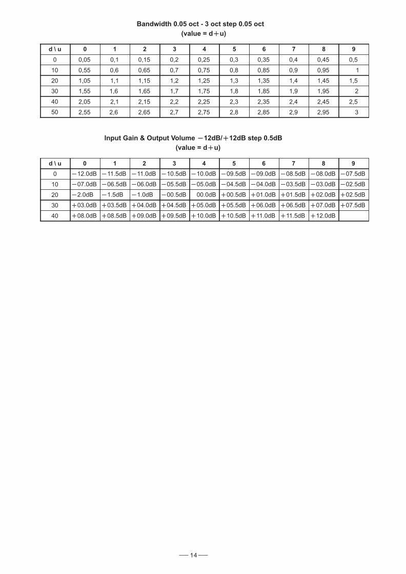
d \ u 0 1 2 3 4 5 6 7 8 9
0 12.0dB 11.5dB 11.0dB 10.5dB 10.0dB 09.5dB 09.0dB 08.5dB 08.0dB 07.5dB
10 07.0dB 06.5dB 06.0dB 05.5dB 05.0dB 04.5dB 04.0dB 03.5dB 03.0dB 02.5dB
20 2.0dB 1.5dB 1.0dB 00.5dB 00.0dB 00.5dB 01.0dB 01.5dB 02.0dB 02.5dB
30 03.0dB 03.5dB 04.0dB 04.5dB 05.0dB 05.5dB 06.0dB 06.5dB 07.0dB 07.5dB
40 08.0dB 08.5dB 09.0dB 09.5dB 10.0dB 10.5dB 11.0dB 11.5dB 12.0dB
Input Gain & Output Volume 12dB/ 12dB step 0.5dB
(value = d u)
Bandwidth 0.05 oct - 3 oct step 0.05 oct
(value = d u)
d \ u 0 1 2 3 4 5 6 7 8 9
0 0,05 0,1 0,15 0,2 0,25 0,3 0,35 0,4 0,45 0,5
10 0,55 0,6 0,65 0,7 0,75 0,8 0,85 0,9 0,95 1
20 1,05 1,1 1,15 1,2 1,25 1,3 1,35 1,4 1,45 1,5
30 1,55 1,6 1,65 1,7 1,75 1,8 1,85 1,9 1,95 2
40 2,05 2,1 2,15 2,2 2,25 2,3 2,35 2,4 2,45 2,5
50 2,55 2,6 2,65 2,7 2,75 2,8 2,85 2,9 2,95 3

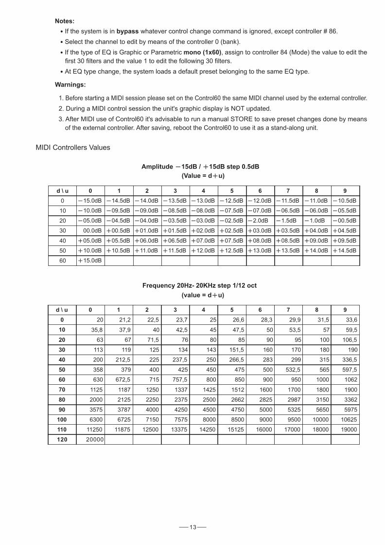
MIDI Controllers Values
d \ u 0 1 2 3 4 5 6 7 8 9
0 15.0dB 14.5dB 14.0dB 13.5dB 13.0dB 12.5dB 12.0dB 11.5dB 11.0dB 10.5dB
10 10.0dB 09.5dB 09.0dB 08.5dB 08.0dB 07.5dB 07.0dB 06.5dB 06.0dB 05.5dB
20 05.0dB 04.5dB 04.0dB 03.5dB 03.0dB 02.5dB 2.0dB 1.5dB 1.0dB 00.5dB
30 00.0dB 00.5dB 01.0dB 01.5dB 02.0dB 02.5dB 03.0dB 03.5dB 04.0dB 04.5dB
40 05.0dB 05.5dB 06.0dB 06.5dB 07.0dB 07.5dB 08.0dB 08.5dB 09.0dB 09.5dB
50 10.0dB 10.5dB 11.0dB 11.5dB 12.0dB 12.5dB 13.0dB 13.5dB 14.0dB 14.5dB
60 15.0dB
Amplitude 15dB / 15dB step 0.5dB
(Value = d u)
Frequency 20Hz- 20KHz step 1/12 oct
(value = d u)
d \ u 0 1 2 3 4 5 6 7 8 9
0 20 21,2 22,5 23,7 25 26,6 28,3 29,9 31,5 33,6
10 35,8 37,9 40 42,5 45 47,5 50 53,5 57 59,5
20 63 67 71,5 76 80 85 90 95 100 106,5
30 113 119 125 134 143 151,5 160 170 180 190
40 200 212,5 225 237,5 250 266,5 283 299 315 336,5
50 358 379 400 425 450 475 500 532,5 565 597,5
60 630 672,5 715 757,5 800 850 900 950 1000 1062
70 1125 1187 1250 1337 1425 1512 1600 1700 1800 1900
80 2000 2125 2250 2375 2500 2662 2825 2987 3150 3362
90 3575 3787 4000 4250 4500 4750 5000 5325 5650 5975
100 6300 6725 7150 7575 8000 8500 9000 9500 10000 10625
110 11250 11875 12500 13375 14250 15125 16000 17000 18000 19000
120 20000
13
1. INTRODUCTION
Purchasing LTO CONTROL60, you purchase a very powerful equalizer, easy to use and contain in very efficienta
single unit rack package.
Our new CONTROL60 is a versatile and very powerful parametric/graphic PRE-EQ. It is based on 2 extremely
powerful high speed 24 32-bit DSPs and very high quality 20-bit A/D and 24-bit D/A converters, thepreserving
pureness of analogue sound in your digital applications. It can be operated in 6 different modes:
Graphic 2 30 Dual Mono 1/3 oct(GR.D.M)
Graphic 2 30 Stereo 1/3 oct(GR.ST)
Graphic 1 60 Mono 1/6 oct(GR.Mono )
Parametric 2 30 Dual Mono(PAR.D.M)
Parametric 2 30 Stereo (PAR.ST)
Parametric 1 60 Mono (PAR.Mono)
allowing the user to obtain the desired sound and timbre out of the musical signals easily.
These algorithms are fully dual mono/stereo algorithms and use very powerful high precision and symmetrical
filters, designed for professional use, able to modify the sound color improving the over sound quality withoutall
introducing any loss or distortion.
4
2. FEATURE LIST
Robust and Compact Design
Digital Stereo Equalizer with 24/32-bit High-Speed DSP Processor
Very High-Quality BurrBrown 20-bit A/D and 24 D/A Converters for Pure and Clean Audio Quality
Open Architecture for Easy Software Updates
MPU Control
2 30 or 1 60 Band Parametric Equalizer
Windows Editor for Easy to Use and Powerful Pc Based MIDI Remote Control
SMT Design for Greater Reliability
Optimized Signal Path to Provide Superior Sound
Manufactured Under QS9000, VDA6.1 Quality System
3. CONTROL ELEMENTS
3.1 The Front Panel
1.Power Switch with LED
2.Channel key with LED
3.Flat key
4.Bypass key LEDwith
5.Utility key LEDwith
6.VU meter key LEDwith
7.AUX key LEDwith
8.HP/LP key with LED
9.Edit key with LED
10.Dial Control knob
11.Enter key
12.Esc key
18 17 15 14 12 9 8 7 6
5 4 3 216 13 11
1
10
Easy to Operate Front Panel Controls and Display
Notes:
If the system is in whatever control change command is ignored, except controller # 86.bypass
Select the channel to edit by means of the controller 0 (bank).
If the type of EQ is Graphic or Parametric , assign to controller 84 (Mode) the value to edit themono (1x60)
first 30 filters and the value 1 to edit the following 30 filters.
At EQ type change, the system loads a default preset belonging to the same EQ type.
Warnings:
1. Before starting a MIDI session please set on the Control60 the same MIDI channel used by the external controller.
2. During a MIDI control session the unit's graphic display is NOT updated.
3. After MIDI use of Control60 it's advisable to run a manual STORE to save preset changes done by means
of the external controller. After saving, reboot the Control60 to use it as a stand-along unit.
ON
OFF
POWER
UP
LEFT RIGHT
DOWN
ENTER
ESC
UTILITY
EDIT
BYPASS
HP/LP
FLAT
AUX
CHANNEL
VU METER
CONTROL6030 30 Band
Digital Equalizer
RLTO
-18
-24
-30
-6
-12
CLIP
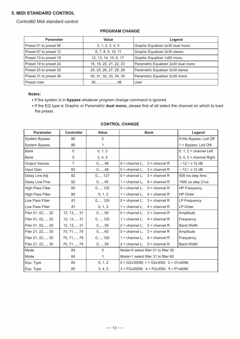
PROGRAM CHANGE
Parameter Value Legend
Preset 01 to preset 06 0, 1, 2, 3, 4, 5 Graphic Equalizer 2x30 dual mono
Preset 07 to preset 12 6, 7, 8, 9, 10, 11 Graphic Equalizer 2x30 stereo
Preset 13 to preset 18 12, 13, 14, 15, 6, 17 Graphic Equalizer 1x60 mono
Preset 19 to preset 24 18, 19, 20, 21, 22, 23 Parametric Equalizer 2x30 dual mono
Preset 25 to preset 30 24, 25, 26, 27, 28, 29 Parametric Equalizer 2x30 stereo
Preset 31 to preset 36 30, 31, 32, 33, 34, 35 Parametric Equalizer 2x30 mono
Preset User 36,..................., 98 User
Notes:
If the system is in whatever program change command is ignored.bypass
If the EQ type is Graphic or Parametric , please first af all select the channel on which to loaddual mono
the preset.
CONTROL CHANGE
5. MIDI STANDARD CONTROL
Control60 Midi standard control
Parameter Controller Value Bank Legend
System Bypass
System Bypass
86
86
0
1
0=No Bypass; Led Off
1 = Bypass; Led ON
Bank
Bank
0
0
0, 1, 2
3, 4, 5
0, 1, 2 = channel Left
3, 4, 5 = channel Right
Output Volume 7 0,..., 48 0 = channel L; 3 = channel R 12 / 12 dB
Input Gain 83 0,..., 48 0 = channel L; 3 = channel R 12 / 12 dB
Delay Line Adj
Delay Line Fine
82
82
0,..., 127
0,..., 95
0 = channel L; 3 = channel R
1 = channel L; 4 = channel R
508 ms step 4ms
1995 us step 21us
High Pass Filter
High Pass Filter
80
80
0,..., 120
0, 1, 2
0 = channel L; 3 = channel R
1 = channel L; 4 = channel R
HP Frequency
HP Order
Low Pass Filter
Low Pass Filter
81
81
0,..., 120
0, 1, 2
0 = channel L; 3 = channel R
1 = channel L; 4 = channel R
LP Frequency
LP Order
Filer 01, 02,..., 20
Filer 01, 02,..., 20
Filer 01, 02,..., 20
12, 13,..., 31
12, 13,..., 31
12, 13,..., 31
0,..., 60
0,..., 120
0,..., 59
0 = channel L; 3 = channel R
1 = channel L; 4 = channel R
2 = channel L; 5 = channel R
Amplitude
Frequency
Band Width
Filer 21, 22,..., 30
Filer 21, 22,..., 30
Filer 21, 22,..., 30
70, 71,..., 79
70, 71,..., 79
70, 71,..., 79
0,..., 60
0,..., 120
0,..., 59
0 = channel L; 3 = channel R
1 = channel L; 4 = channel R
2 = channel L; 5 = channel R
Amplitude
Frequency
Band Width
Mode
Mode
84
84
0
1
Mode=0 select filter 01 to filter 30
Mode=1 select filter 31 to filter 60
Equ. Type
Equ. Type
85
85
0, 1, 2
3, 4, 5
0 = G2x30DM; 1 = G2x30St; 2 = G1x60M;
3 = P2x30DM; 4 = P2x30St; 5 = P1x60M;
12
Power Switch With LED (1)
Turns the apparatus on and off. Press the SW, the power LED inside the SW will turn on.
Dial Control Knob (10)
Used only to change editable values.
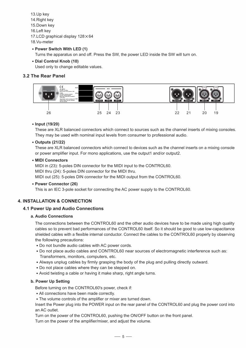
3.2 The Rear Panel
Input (19/20)
These are XLR balanced connectors which connect to sources such as the channel inserts of mixing consoles.
They may be used with nominal input levels from consumer to professional audio.
Outputs (21/22)
These are XLR balanced connectors which connect to devices such as the channel inserts on a mixing console
or power amplifier input. For mono applications, use the output1 and/or output2.
MIDI Connectors
MIDI in (23): 5-poles DIN connector for the MIDI input to the CONTROL60.
MIDI thru (24): 5-poles DIN connector for the MIDI thru.
MIDI out (25): 5-poles DIN connector for the MIDI output from the CONTROL60.
Power Connector (26)
This is an IEC 3-pole socket for connecting the AC power supply to the CONTROL60.
4. INSTALLATION & CONNECTION
4.1 Power Up and Audio Connections
a. Audio Connections
b. Power Up Setting
The connections between the CONTROL60 and the other audio devices have to be made using high quality
cables so to prevent bad performances of the CONTROL60 itself. So it should be good to use low-capacitance
shielded cables with a flexible internal conductor. Connect the cables to the CONTROL60 properly by observing
the following precautions:
Do not bundle audio cables with AC power cords.
Do not place audio cables and CONTROL60 near sources of electromagnetic interference such as:
Transformers, monitors, computers, etc.
Always unplug cables by firmly grasping the body of the plug and pulling directly outward.
Do not place cables where they can be stepped on.
Before turning on the CONTROL60's power, check if:
All connections have been made correctly.
The volume controls of the amplifier or mixer are turned down.
Insert the Power plug into the POWER input on the rear panel of the CONTROL60 and plug the power cord into
an AC outlet.
Turn on the power of the CONTROL60, pushing the ON/OFF button on the front panel.
Turn on the power of the amplifier/mixer, and adjust the volume.
13.Up key
14.Right key
15.Down key
16.Left key
17.LCD graphical display 128 64
18.Vu-meter
INPUT1INPUT2OUTPUT1OUTPUT2INPUTTHRUOUTPUT
MIDIAC INPUT95-240V 60-50HzRated Power Consumption 15W
FUSE:210-240V: T250mAL 250VAC95-120V: 500mA 250VACREPLACE FUSE WITH CORRECTTYPE ONLY
Apparaten skall anslutas tilljordat uttag nar den anslutstill ett natverk
25 24 23 22 21 20 1926
5
PUSH
2 13
NEW TIDE
PUSH
2 13
NEW TIDE
Avoid twisting a cable or having it make sharp, right angle turns.
SERIAL
MODEL
CODE
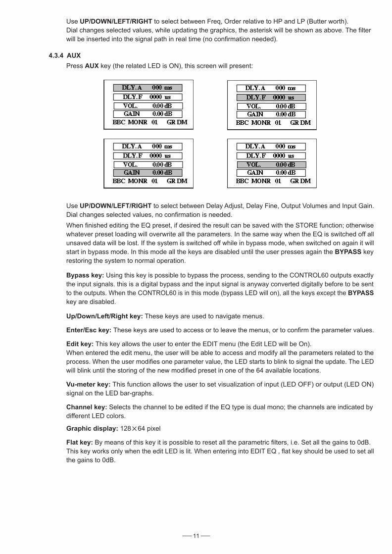
4.3.4 AUX
Press key (the related LED is ON), this screen will present:AUX
Up/Down/Left/Right key: These keys are used to navigate menus.
Enter/Esc key: These keys are used to access or to leave the menus, or to confirm the parameter values.
Graphic display: 128 64 pixel
11
a. Standard Use
The CONTROL60 may be placed almost anywhere: on a table, on top of an amp, next to a mixing console. If it will
be on furniture, check the rubber feet provided to the bottom of the unit. Make sure to place the CONTROL60 away
from other audio equipment that may induce fields, and away from the signal wiring.
It is possible that CONTROL60 may pick up noise fields generated by other equipment such as large power amplifiers;
in this case, move the CONTROL60 until the noise goes away.
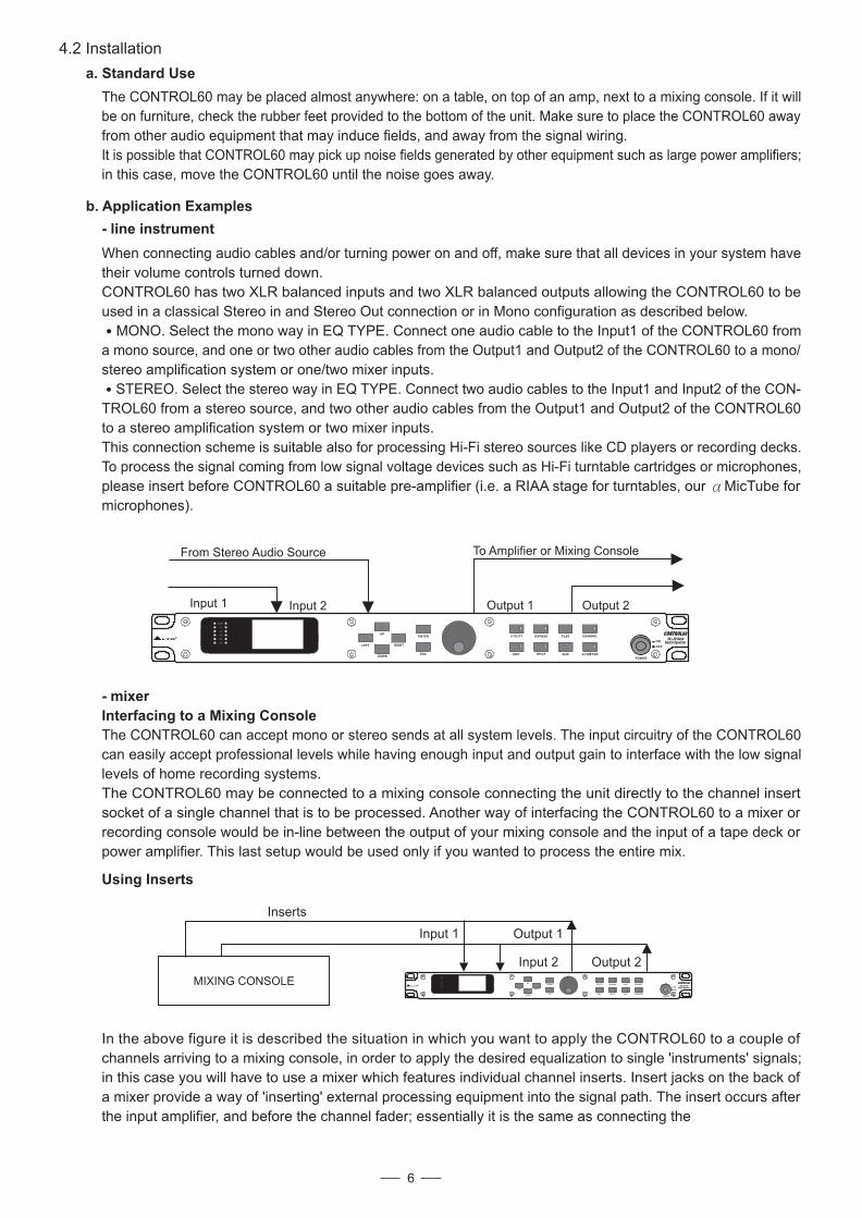
b. Application Examples
- line instrument
To Amplifier or Mixing Console
Output 2Output 1
From Stereo Audio Source
Input 2Input 1
- mixer
Interfacing to a Mixing Console
4.2 Installation
6
ON
OFF
POWER
UP
LEFT RIGHT
DOWN
ENTER
ESC
UTILITY
EDIT
BYPASS
HP/LP
FLAT
AUX
CHANNEL
VU METER
CONTROL6030 30 Band
Digital Equalizer
RLTO
-18
-24
-30
-6
-12
CLIP
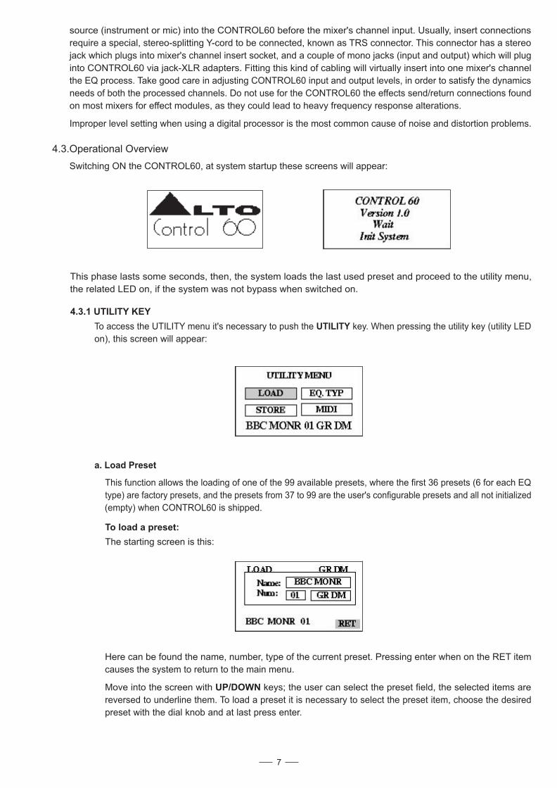
Using Inserts
MIXING CONSOLE
Input 1 Output 1
Input 2 Output 2
Inserts
When connecting audio cables and/or turning power on and off, make sure that all devices in your system have
their volume controls turned down.
CONTROL60 has two XLR balanced inputs and two XLR balanced outputs allowing the CONTROL60 to be
used in a classical Stereo in and Stereo Out connection or in Mono configuration as described below.
MONO. Select the mono way in EQ TYPE. Connect one audio cable to the of the CONTROL60 fromInput1
a mono source, and one or two other audio cables from the Output1 and Output2 of the CONTROL60 to a mono/
stereo amplification system or one/two mixer inputs.
STEREO. Select the stereo way in EQ TYPE. Connect two audio cables to the Input1 and Input2 of the CON-
TROL60 from a stereo source, and two other audio cables from the Output1 and Output2 of the CONTROL60
to a stereo amplification system or two mixer inputs.
This connection scheme is suitable also for processing Hi-Fi stereo sources like CD players or recording decks.
To process the signal coming from low signal voltage devices such as Hi-Fi turntable cartridges or microphones,
please insert before CONTROL60 a suitable pre-amplifier (i.e. a RIAA stage for turntables, our MicTube for
microphones).
The CONTROL60 can accept mono or stereo sends at all system levels. The input circuitry of the CONTROL60
can easily accept professional levels while having enough input and output gain to interface with the low signal
levels of home recording systems.
The CONTROL60 may be connected to a mixing console connecting the unit directly to the channel insert
socket of a single channel that is to be processed. Another way of interfacing the CONTROL60 to a mixer or
recording console would be in-line between the output of your mixing console and the input of a tape deck or
power amplifier. This last setup would be used only if you wanted to process the entire mix.
Use to select between Freq, Order relative to HP and LP (Butter worth).
Dial changes selected values, while updating the graphics, the asterisk will be shown as above. The filter
will be inserted into the signal path in real time (no confirmation needed).
UP/DOWN/LEFT/RIGHT
Use to select between Delay Adjust, Delay Fine, Output Volumes and Input Gain.UP/DOWN/LEFT/RIGHT
Dial changes selected values, no confirmation is needed.
When finished editing the EQ preset, if desired the result can be saved with the STORE function; otherwise
whatever preset loading will overwrite all the parameters. In the same way when the EQ is switched off all
unsaved data will be lost. If the system is switched off while in bypass mode, when switched on again it will
start in bypass mode. In this mode all the keys are disabled until the user presses again the keyBYPASS
restoring the system to normal operation.
Bypass key: Using this key is possible to bypass the process, sending to the CONTROL60 outputs exactly
the input signals. this is a digital bypass and the input signal is anyway converted digitally before to be sent
to the outputs. When the CONTROL60 is in this mode (bypass LED will on), all the keys except the BYPASS
key are disabled.
Edit key: This key allows the user to enter the EDIT menu (the Edit LED will be On).
When entered the edit menu, the user will be able to access and modify all the parameters related to the
process. When the user modifies one parameter value, the LED starts to blink to signal the update. The LED
will blink until the storing of the new modified preset in one of the 64 available locations.
Flat key: By means of this key it is possible to reset all the parametric filters, i.e. Set all the gains to 0dB.
This key works only when the edit LED is lit. When entering into EDIT EQ , flat key should be used to set all
the gains to 0dB.
Channel key: Selects the channel to be edited if the EQ type is dual mono; the channels are indicated by
different LED colors.
Vu-meter key: This function allows the user to set visualization of input (LED OFF) or output (LED ON)
signal on the LED bar-graphs.
In the above figure it is described the situation in which you want to apply the CONTROL60 to a couple of
channels arriving to a mixing console, in order to apply the desired equalization to single 'instruments' signals;
in this case you will have to use a mixer which features individual channel inserts. Insert jacks on the back of
a mixer provide a way of 'inserting' external processing equipment into the signal path. The insert occurs after
the input amplifier, and before the channel fader; essentially it is the same as connecting the
ON
OFF
POWER
UP
LEFT RIGHT
DOWN
ENTER
ESC
UTILITY
EDIT
BYPASS
HP/LP
FLAT
AUX
CHANNEL
VU METER
CONTROL6030 30 Band
Digital Equalizer
RLTO
-18
-24
-30
-6
-12
CLIP
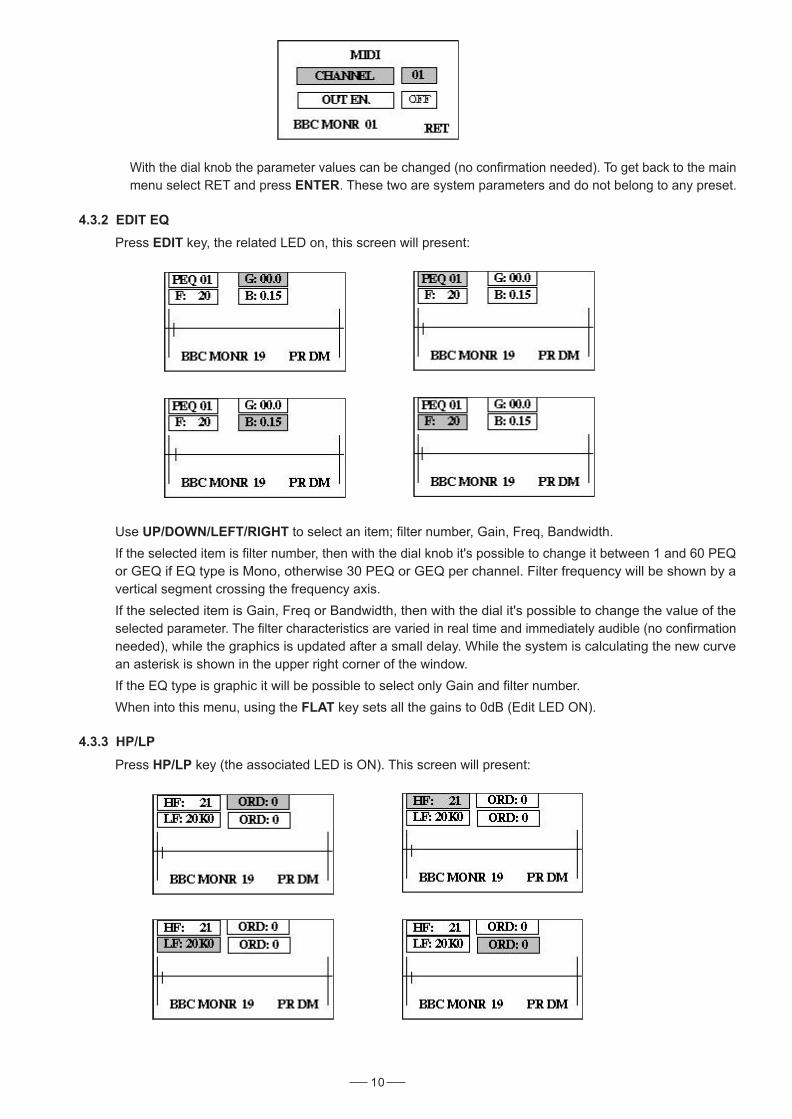
With the dial knob the parameter values can be changed (no confirmation needed). To get back to the main
menu select RET and press . These two are system parameters and do not belong to any preset.ENTER
4.3.2 EDIT EQ
Press key, the related LED on, this screen will present:EDIT
Use to select an item; filter number, Gain, Freq, Bandwidth.UP/DOWN/LEFT/RIGHT
If the selected item is filter number, then with the dial knob it's possible to change it between 1 and 60 PEQ
or GEQ if EQ type is Mono, otherwise 30 PEQ or GEQ per channel. Filter frequency will be shown by a
vertical segment crossing the frequency axis.
If the selected item is Gain, Freq or Bandwidth, then with the dial it's possible to change the value of the
selected parameter. The filter characteristics are varied in real time and immediately audible (no confirmation
needed), while the graphics is updated after a small delay. While the system is calculating the new curve
an asterisk is shown in the upper right corner of the window.
If the EQ type is graphic it will be possible to select only Gain and filter number.
When into this menu, using the key sets all the gains to 0dB (Edit LED ON).FLAT
10
4.3.3 HP/LP
Press key (the associated LED is ON). This screen will present:HP/LP
This function allows the loading of one of the 99 available presets, where the first 36 presets (6 for each EQ
type) are factory presets, and the presets from configurable presets and all not initialized37 to 99 are the user's
(empty) when CONTROL60 is shipped.
4.3.Operational Overview
Switching ON the CONTROL60, at system startup these screens will appear:
This phase lasts some seconds, then, the system loads the last used preset and proceed to the utility menu,
the related LED on, if the system was not bypass when switched on.
4.3.1 UTILITY KEY
To access the UTILITY menu it's necessary to push the key. When pressing the utility key LEDUTILITY (utility
on), this screen will appear:
To load a preset:
The starting screen is this:
7
a. Load Preset
Here can be found the name, number, type of the current preset. Pressing enter when on the RET item
causes the system to return to the main menu.
Move into the screen with keys; the user can select the preset field, the selected itemsUP/DOWN are
reversed to underline them. To load a preset it is necessary to select the preset item, choose the desired
preset with the dial knob and at last press enter.
source (instrument or mic) into the CONTROL60 before the mixer's channel input. Usually, insert connections
require a special, stereo-splitting Y-cord to be connected, known as TRS connector. This connector has a stereo
jack which plugs into mixer's channel insert socket, and a couple of mono jacks (input and output) which will plug
into CONTROL60 via jack-XLR adapters. Fitting this kind of cabling will virtually insert into one mixer's channel
the EQ process. Take good care in adjusting CONTROL60 input and output levels, in order to satisfy the dynamics
needs of both the processed channels. Do not use for the CONTROL60 the effects send/return connections found
on most mixers for effect modules, as they could lead to heavy frequency response alterations.
Improper level setting when using a digital processor is the most common cause of noise and distortion problems.
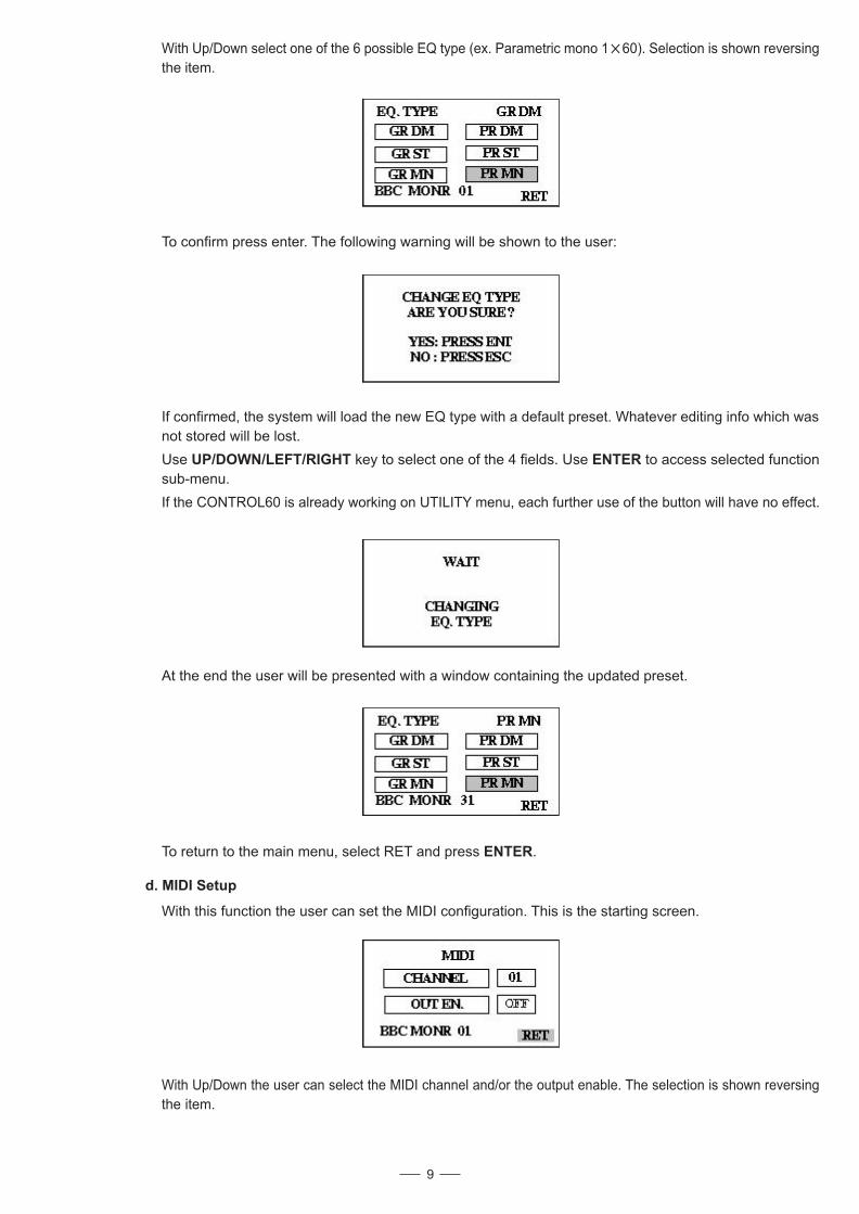
With Up/Down select one of the 6 possible EQ type (ex. Parametric mono 1 60). Selection is shown reversing
the item.
To confirm press enter. The following warning will be shown to the user:
At the end the user will be presented with a window containing the updated preset.
To return to the main menu, select RET and press .ENTER
9
With this function the user can set the MIDI configuration. This is the starting screen.
With Up/Down the user can select the MIDI channel and/or the output enable. The selection is shown reversing
the item.
d. MIDI Setup
8
b. Store Preset
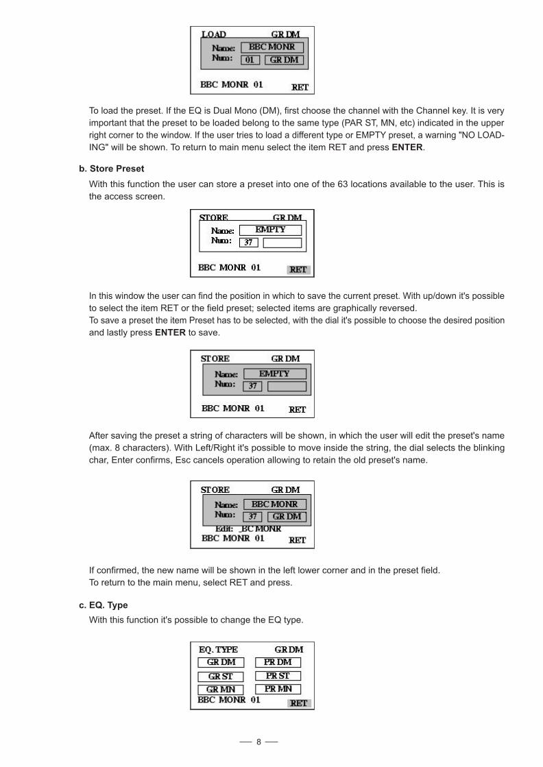
If confirmed, the new name will be shown in the left lower corner and in the preset field.
To return to the main menu, select RET and press.
With this function it's possible to change the EQ type.
c. EQ. Type
To load the preset. If the EQ is Dual Mono (DM), first choose the channel with the Channel key. It is very
important that the preset to be loaded belong to the same type (PAR ST, MN, etc) indicated in the upper
right corner to the window. If the user tries to load a different type or EMPTY preset, a warning "NO LOAD-
ING" will be shown. To return to main menu select the item RET and press .ENTER
With this function the user can store a preset into one of the cations available to the user. This is63 lo
the access screen.
In this window the user can find the position in which to save the current preset. With up/down it's possible
to select the item RET or the field preset; selected items are graphically reversed.
To save a preset the item Preset has to be selected, with the dial it's possible to choose the desired position
and lastly press to save.ENTER
After saving the preset a string of characters will be shown, in which the user will edit the preset's name
(max. 8 characters). With Left/Right it's possible to move inside the string, the dial selects the blinking
char, Enter confirms, Esc cancels operation allowing to retain the old preset's name.
If confirmed, the system will load the new EQ type with a default preset. Whatever editing info which was
not stored will be lost.
Use key to select one of the 4 fields. Use to access selected functionUP/DOWN/LEFT/RIGHT ENTER
sub-menu.
If the CONTROL60 is already working on UTILITY menu, each further use of the button will have no effect.
With Up/Down select one of the 6 possible EQ type (ex. Parametric mono 1 60). Selection is shown reversing
the item.
To confirm press enter. The following warning will be shown to the user:
At the end the user will be presented with a window containing the updated preset.
To return to the main menu, select RET and press .ENTER
9
With this function the user can set the MIDI configuration. This is the starting screen.
With Up/Down the user can select the MIDI channel and/or the output enable. The selection is shown reversing
the item.
d. MIDI Setup
8
b. Store Preset
If confirmed, the new name will be shown in the left lower corner and in the preset field.
To return to the main menu, select RET and press.
With this function it's possible to change the EQ type.
c. EQ. Type
To load the preset. If the EQ is Dual Mono (DM), first choose the channel with the Channel key. It is very
important that the preset to be loaded belong to the same type (PAR ST, MN, etc) indicated in the upper
right corner to the window. If the user tries to load a different type or EMPTY preset, a warning "NO LOAD-
ING" will be shown. To return to main menu select the item RET and press .ENTER
With this function the user can store a preset into one of the cations available to the user. This is63 lo
the access screen.
In this window the user can find the position in which to save the current preset. With up/down it's possible
to select the item RET or the field preset; selected items are graphically reversed.
To save a preset the item Preset has to be selected, with the dial it's possible to choose the desired position
and lastly press to save.ENTER
After saving the preset a string of characters will be shown, in which the user will edit the preset's name
(max. 8 characters). With Left/Right it's possible to move inside the string, the dial selects the blinking
char, Enter confirms, Esc cancels operation allowing to retain the old preset's name.
If confirmed, the system will load the new EQ type with a default preset. Whatever editing info which was
not stored will be lost.
Use key to select one of the 4 fields. Use to access selected functionUP/DOWN/LEFT/RIGHT ENTER
sub-menu.
If the CONTROL60 is already working on UTILITY menu, each further use of the button will have no effect.
With the dial knob the parameter values can be changed (no confirmation needed). To get back to the main
menu select RET and press . These two are system parameters and do not belong to any preset.ENTER
4.3.2 EDIT EQ
Press key, the related LED on, this screen will present:EDIT
Use to select an item; filter number, Gain, Freq, Bandwidth.UP/DOWN/LEFT/RIGHT
If the selected item is filter number, then with the dial knob it's possible to change it between 1 and 60 PEQ
or GEQ if EQ type is Mono, otherwise 30 PEQ or GEQ per channel. Filter frequency will be shown by a
vertical segment crossing the frequency axis.
If the selected item is Gain, Freq or Bandwidth, then with the dial it's possible to change the value of the
selected parameter. The filter characteristics are varied in real time and immediately audible (no confirmation
needed), while the graphics is updated after a small delay. While the system is calculating the new curve
an asterisk is shown in the upper right corner of the window.
If the EQ type is graphic it will be possible to select only Gain and filter number.
When into this menu, using the key sets all the gains to 0dB (Edit LED ON).FLAT
10
4.3.3 HP/LP
Press key (the associated LED is ON). This screen will present:HP/LP
This function allows the loading of one of the 99 available presets, where the first 36 presets (6 for each EQ
type) are factory presets, and the presets from configurable presets and all not initialized37 to 99 are the user's
(empty) when CONTROL60 is shipped.
4.3.Operational Overview
Switching ON the CONTROL60, at system startup these screens will appear:
This phase lasts some seconds, then, the system loads the last used preset and proceed to the utility menu,
the related LED on, if the system was not bypass when switched on.
4.3.1 UTILITY KEY
To access the UTILITY menu it's necessary to push the key. When pressing the utility key LEDUTILITY (utility
on), this screen will appear:
To load a preset:
The starting screen is this:
7
a. Load Preset
Here can be found the name, number, type of the current preset. Pressing enter when on the RET item
causes the system to return to the main menu.
Move into the screen with keys; the user can select the preset field, the selected itemsUP/DOWN are
reversed to underline them. To load a preset it is necessary to select the preset item, choose the desired
preset with the dial knob and at last press enter.
source (instrument or mic) into the CONTROL60 before the mixer's channel input. Usually, insert connections
require a special, stereo-splitting Y-cord to be connected, known as TRS connector. This connector has a stereo
jack which plugs into mixer's channel insert socket, and a couple of mono jacks (input and output) which will plug
into CONTROL60 via jack-XLR adapters. Fitting this kind of cabling will virtually insert into one mixer's channel
the EQ process. Take good care in adjusting CONTROL60 input and output levels, in order to satisfy the dynamics
needs of both the processed channels. Do not use for the CONTROL60 the effects send/return connections found
on most mixers for effect modules, as they could lead to heavy frequency response alterations.
Improper level setting when using a digital processor is the most common cause of noise and distortion problems.
4.3.4 AUX
Press key (the related LED is ON), this screen will present:AUX
Up/Down/Left/Right key: These keys are used to navigate menus.
Enter/Esc key: These keys are used to access or to leave the menus, or to confirm the parameter values.
Graphic display: 128 64 pixel
11
a. Standard Use
The CONTROL60 may be placed almost anywhere: on a table, on top of an amp, next to a mixing console. If it will
be on furniture, check the rubber feet provided to the bottom of the unit. Make sure to place the CONTROL60 away
from other audio equipment that may induce fields, and away from the signal wiring.
It is possible that CONTROL60 may pick up noise fields generated by other equipment such as large power amplifiers;
in this case, move the CONTROL60 until the noise goes away.
b. Application Examples
- line instrument
To Amplifier or Mixing Console
Output 2Output 1
From Stereo Audio Source
Input 2Input 1
- mixer
Interfacing to a Mixing Console
4.2 Installation
6
ON
OFF
POWER
UP
LEFT RIGHT
DOWN
ENTER
ESC
UTILITY
EDIT
BYPASS
HP/LP
FLAT
AUX
CHANNEL
VU METER
CONTROL6030 30 Band
Digital Equalizer
RLTO
-18
-24
-30
-6
-12
CLIP
Using Inserts
MIXING CONSOLE
Input 1 Output 1
Input 2 Output 2
Inserts
When connecting audio cables and/or turning power on and off, make sure that all devices in your system have
their volume controls turned down.
CONTROL60 has two XLR balanced inputs and two XLR balanced outputs allowing the CONTROL60 to be
used in a classical Stereo in and Stereo Out connection or in Mono configuration as described below.
MONO. Select the mono way in EQ TYPE. Connect one audio cable to the of the CONTROL60 fromInput1
a mono source, and one or two other audio cables from the Output1 and Output2 of the CONTROL60 to a mono/
stereo amplification system or one/two mixer inputs.
STEREO. Select the stereo way in EQ TYPE. Connect two audio cables to the Input1 and Input2 of the CON-
TROL60 from a stereo source, and two other audio cables from the Output1 and Output2 of the CONTROL60
to a stereo amplification system or two mixer inputs.
This connection scheme is suitable also for processing Hi-Fi stereo sources like CD players or recording decks.
To process the signal coming from low signal voltage devices such as Hi-Fi turntable cartridges or microphones,
please insert before CONTROL60 a suitable pre-amplifier (i.e. a RIAA stage for turntables, our MicTube for
microphones).
The CONTROL60 can accept mono or stereo sends at all system levels. The input circuitry of the CONTROL60
can easily accept professional levels while having enough input and output gain to interface with the low signal
levels of home recording systems.
The CONTROL60 may be connected to a mixing console connecting the unit directly to the channel insert
socket of a single channel that is to be processed. Another way of interfacing the CONTROL60 to a mixer or
recording console would be in-line between the output of your mixing console and the input of a tape deck or
power amplifier. This last setup would be used only if you wanted to process the entire mix.
Use to select between Freq, Order relative to HP and LP (Butter worth).
Dial changes selected values, while updating the graphics, the asterisk will be shown as above. The filter
will be inserted into the signal path in real time (no confirmation needed).
UP/DOWN/LEFT/RIGHT
Use to select between Delay Adjust, Delay Fine, Output Volumes and Input Gain.UP/DOWN/LEFT/RIGHT
Dial changes selected values, no confirmation is needed.
When finished editing the EQ preset, if desired the result can be saved with the STORE function; otherwise
whatever preset loading will overwrite all the parameters. In the same way when the EQ is switched off all
unsaved data will be lost. If the system is switched off while in bypass mode, when switched on again it will
start in bypass mode. In this mode all the keys are disabled until the user presses again the keyBYPASS
restoring the system to normal operation.
Bypass key: Using this key is possible to bypass the process, sending to the CONTROL60 outputs exactly
the input signals. this is a digital bypass and the input signal is anyway converted digitally before to be sent
to the outputs. When the CONTROL60 is in this mode (bypass LED will on), all the keys except the BYPASS
key are disabled.
Edit key: This key allows the user to enter the EDIT menu (the Edit LED will be On).
When entered the edit menu, the user will be able to access and modify all the parameters related to the
process. When the user modifies one parameter value, the LED starts to blink to signal the update. The LED
will blink until the storing of the new modified preset in one of the 64 available locations.
Flat key: By means of this key it is possible to reset all the parametric filters, i.e. Set all the gains to 0dB.
This key works only when the edit LED is lit. When entering into EDIT EQ , flat key should be used to set all
the gains to 0dB.
Channel key: Selects the channel to be edited if the EQ type is dual mono; the channels are indicated by
different LED colors.
Vu-meter key: This function allows the user to set visualization of input (LED OFF) or output (LED ON)
signal on the LED bar-graphs.
In the above figure it is described the situation in which you want to apply the CONTROL60 to a couple of
channels arriving to a mixing console, in order to apply the desired equalization to single 'instruments' signals;
in this case you will have to use a mixer which features individual channel inserts. Insert jacks on the back of
a mixer provide a way of 'inserting' external processing equipment into the signal path. The insert occurs after
the input amplifier, and before the channel fader; essentially it is the same as connecting the
ON
OFF
POWER
UP
LEFT RIGHT
DOWN
ENTER
ESC
UTILITY
EDIT
BYPASS
HP/LP
FLAT
AUX
CHANNEL
VU METER
CONTROL6030 30 Band
Digital Equalizer
RLTO
-18
-24
-30
-6
-12
CLIP
PROGRAM CHANGE
Parameter Value Legend
Preset 01 to preset 06 0, 1, 2, 3, 4, 5 Graphic Equalizer 2x30 dual mono
Preset 07 to preset 12 6, 7, 8, 9, 10, 11 Graphic Equalizer 2x30 stereo
Preset 13 to preset 18 12, 13, 14, 15, 6, 17 Graphic Equalizer 1x60 mono
Preset 19 to preset 24 18, 19, 20, 21, 22, 23 Parametric Equalizer 2x30 dual mono
Preset 25 to preset 30 24, 25, 26, 27, 28, 29 Parametric Equalizer 2x30 stereo
Preset 31 to preset 36 30, 31, 32, 33, 34, 35 Parametric Equalizer 2x30 mono
Preset User 36,..................., 98 User
Notes:
If the system is in whatever program change command is ignored.bypass
If the EQ type is Graphic or Parametric , please first af all select the channel on which to loaddual mono
the preset.
CONTROL CHANGE
5. MIDI STANDARD CONTROL
Control60 Midi standard control
Parameter Controller Value Bank Legend
System Bypass
System Bypass
86
86
0
1
0=No Bypass; Led Off
1 = Bypass; Led ON
Bank
Bank
0
0
0, 1, 2
3, 4, 5
0, 1, 2 = channel Left
3, 4, 5 = channel Right
Output Volume 7 0,..., 48 0 = channel L; 3 = channel R 12 / 12 dB
Input Gain 83 0,..., 48 0 = channel L; 3 = channel R 12 / 12 dB
Delay Line Adj
Delay Line Fine
82
82
0,..., 127
0,..., 95
0 = channel L; 3 = channel R
1 = channel L; 4 = channel R
508 ms step 4ms
1995 us step 21us
High Pass Filter
High Pass Filter
80
80
0,..., 120
0, 1, 2
0 = channel L; 3 = channel R
1 = channel L; 4 = channel R
HP Frequency
HP Order
Low Pass Filter
Low Pass Filter
81
81
0,..., 120
0, 1, 2
0 = channel L; 3 = channel R
1 = channel L; 4 = channel R
LP Frequency
LP Order
Filer 01, 02,..., 20
Filer 01, 02,..., 20
Filer 01, 02,..., 20
12, 13,..., 31
12, 13,..., 31
12, 13,..., 31
0,..., 60
0,..., 120
0,..., 59
0 = channel L; 3 = channel R
1 = channel L; 4 = channel R
2 = channel L; 5 = channel R
Amplitude
Frequency
Band Width
Filer 21, 22,..., 30
Filer 21, 22,..., 30
Filer 21, 22,..., 30
70, 71,..., 79
70, 71,..., 79
70, 71,..., 79
0,..., 60
0,..., 120
0,..., 59
0 = channel L; 3 = channel R
1 = channel L; 4 = channel R
2 = channel L; 5 = channel R
Amplitude
Frequency
Band Width
Mode
Mode
84
84
0
1
Mode=0 select filter 01 to filter 30
Mode=1 select filter 31 to filter 60
Equ. Type
Equ. Type
85
85
0, 1, 2
3, 4, 5
0 = G2x30DM; 1 = G2x30St; 2 = G1x60M;
3 = P2x30DM; 4 = P2x30St; 5 = P1x60M;
12
Power Switch With LED (1)
Turns the apparatus on and off. Press the SW, the power LED inside the SW will turn on.
Dial Control Knob (10)
Used only to change editable values.
3.2 The Rear Panel
Input (19/20)
These are XLR balanced connectors which connect to sources such as the channel inserts of mixing consoles.
They may be used with nominal input levels from consumer to professional audio.
Outputs (21/22)
These are XLR balanced connectors which connect to devices such as the channel inserts on a mixing console
or power amplifier input. For mono applications, use the output1 and/or output2.
MIDI Connectors
MIDI in (23): 5-poles DIN connector for the MIDI input to the CONTROL60.
MIDI thru (24): 5-poles DIN connector for the MIDI thru.
MIDI out (25): 5-poles DIN connector for the MIDI output from the CONTROL60.
Power Connector (26)
This is an IEC 3-pole socket for connecting the AC power supply to the CONTROL60.
4. INSTALLATION & CONNECTION
4.1 Power Up and Audio Connections
a. Audio Connections
b. Power Up Setting
The connections between the CONTROL60 and the other audio devices have to be made using high quality
cables so to prevent bad performances of the CONTROL60 itself. So it should be good to use low-capacitance
shielded cables with a flexible internal conductor. Connect the cables to the CONTROL60 properly by observing
the following precautions:
Do not bundle audio cables with AC power cords.
Do not place audio cables and CONTROL60 near sources of electromagnetic interference such as:
Transformers, monitors, computers, etc.
Always unplug cables by firmly grasping the body of the plug and pulling directly outward.
Do not place cables where they can be stepped on.
Before turning on the CONTROL60's power, check if:
All connections have been made correctly.
The volume controls of the amplifier or mixer are turned down.
Insert the Power plug into the POWER input on the rear panel of the CONTROL60 and plug the power cord into
an AC outlet.
Turn on the power of the CONTROL60, pushing the ON/OFF button on the front panel.
Turn on the power of the amplifier/mixer, and adjust the volume.
13.Up key
14.Right key
15.Down key
16.Left key
17.LCD graphical display 128 64
18.Vu-meter
INPUT1INPUT2OUTPUT1OUTPUT2INPUTTHRUOUTPUT
MIDIAC INPUT95-240V 60-50HzRated Power Consumption 15W
FUSE:210-240V: T250mAL 250VAC95-120V: 500mA 250VACREPLACE FUSE WITH CORRECTTYPE ONLY
Apparaten skall anslutas tilljordat uttag nar den anslutstill ett natverk
25 24 23 22 21 20 1926
5
PUSH
2 13
NEW TIDE
PUSH
2 13
NEW TIDE
Avoid twisting a cable or having it make sharp, right angle turns.
SERIAL
MODEL
CODE
MIDI Controllers Values
d \ u 0 1 2 3 4 5 6 7 8 9
0 15.0dB 14.5dB 14.0dB 13.5dB 13.0dB 12.5dB 12.0dB 11.5dB 11.0dB 10.5dB
10 10.0dB 09.5dB 09.0dB 08.5dB 08.0dB 07.5dB 07.0dB 06.5dB 06.0dB 05.5dB
20 05.0dB 04.5dB 04.0dB 03.5dB 03.0dB 02.5dB 2.0dB 1.5dB 1.0dB 00.5dB
30 00.0dB 00.5dB 01.0dB 01.5dB 02.0dB 02.5dB 03.0dB 03.5dB 04.0dB 04.5dB
40 05.0dB 05.5dB 06.0dB 06.5dB 07.0dB 07.5dB 08.0dB 08.5dB 09.0dB 09.5dB
50 10.0dB 10.5dB 11.0dB 11.5dB 12.0dB 12.5dB 13.0dB 13.5dB 14.0dB 14.5dB
60 15.0dB
Amplitude 15dB / 15dB step 0.5dB
(Value = d u)
Frequency 20Hz- 20KHz step 1/12 oct
(value = d u)
d \ u 0 1 2 3 4 5 6 7 8 9
0 20 21,2 22,5 23,7 25 26,6 28,3 29,9 31,5 33,6
10 35,8 37,9 40 42,5 45 47,5 50 53,5 57 59,5
20 63 67 71,5 76 80 85 90 95 100 106,5
30 113 119 125 134 143 151,5 160 170 180 190
40 200 212,5 225 237,5 250 266,5 283 299 315 336,5
50 358 379 400 425 450 475 500 532,5 565 597,5
60 630 672,5 715 757,5 800 850 900 950 1000 1062
70 1125 1187 1250 1337 1425 1512 1600 1700 1800 1900
80 2000 2125 2250 2375 2500 2662 2825 2987 3150 3362
90 3575 3787 4000 4250 4500 4750 5000 5325 5650 5975
100 6300 6725 7150 7575 8000 8500 9000 9500 10000 10625
110 11250 11875 12500 13375 14250 15125 16000 17000 18000 19000
120 20000
13
1. INTRODUCTION
Purchasing LTO CONTROL60, you purchase a very powerful equalizer, easy to use and contain in very efficienta
single unit rack package.
Our new CONTROL60 is a versatile and very powerful parametric/graphic PRE-EQ. It is based on 2 extremely
powerful high speed 24 32-bit DSPs and very high quality 20-bit A/D and 24-bit D/A converters, thepreserving
pureness of analogue sound in your digital applications. It can be operated in 6 different modes:
Graphic 2 30 Dual Mono 1/3 oct(GR.D.M)
Graphic 2 30 Stereo 1/3 oct(GR.ST)
Graphic 1 60 Mono 1/6 oct(GR.Mono )
Parametric 2 30 Dual Mono(PAR.D.M)
Parametric 2 30 Stereo (PAR.ST)
Parametric 1 60 Mono (PAR.Mono)
allowing the user to obtain the desired sound and timbre out of the musical signals easily.
These algorithms are fully dual mono/stereo algorithms and use very powerful high precision and symmetrical
filters, designed for professional use, able to modify the sound color improving the over sound quality withoutall
introducing any loss or distortion.
4
2. FEATURE LIST
Robust and Compact Design
Digital Stereo Equalizer with 24/32-bit High-Speed DSP Processor
Very High-Quality BurrBrown 20-bit A/D and 24 D/A Converters for Pure and Clean Audio Quality
Open Architecture for Easy Software Updates
MPU Control
2 30 or 1 60 Band Parametric Equalizer
Windows Editor for Easy to Use and Powerful Pc Based MIDI Remote Control
SMT Design for Greater Reliability
Optimized Signal Path to Provide Superior Sound
Manufactured Under QS9000, VDA6.1 Quality System
3. CONTROL ELEMENTS
3.1 The Front Panel
1.Power Switch with LED
2.Channel key with LED
3.Flat key
4.Bypass key LEDwith
5.Utility key LEDwith
6.VU meter key LEDwith
7.AUX key LEDwith
8.HP/LP key with LED
9.Edit key with LED
10.Dial Control knob
11.Enter key
12.Esc key
18 17 15 14 12 9 8 7 6
5 4 3 216 13 11
1
10
Easy to Operate Front Panel Controls and Display
Notes:
If the system is in whatever control change command is ignored, except controller # 86.bypass
Select the channel to edit by means of the controller 0 (bank).
If the type of EQ is Graphic or Parametric , assign to controller 84 (Mode) the value to edit themono (1x60)
first 30 filters and the value 1 to edit the following 30 filters.
At EQ type change, the system loads a default preset belonging to the same EQ type.
Warnings:
1. Before starting a MIDI session please set on the Control60 the same MIDI channel used by the external controller.
2. During a MIDI control session the unit's graphic display is NOT updated.
3. After MIDI use of Control60 it's advisable to run a manual STORE to save preset changes done by means
of the external controller. After saving, reboot the Control60 to use it as a stand-along unit.
ON
OFF
POWER
UP
LEFT RIGHT
DOWN
ENTER
ESC
UTILITY
EDIT
BYPASS
HP/LP
FLAT
AUX
CHANNEL
VU METER
CONTROL6030 30 Band
Digital Equalizer
RLTO
-18
-24
-30
-6
-12
CLIP
14
TABLE OF CONTENTS
1. INTRODUCTION .......................................................................................... ..................................4........
2. FEATURE LIST ......................................................................................................................................4
3. CONTROL ELEMENTS ............................................................................. .............................................4
3.1 The Front Panel
3.2 The Rear Panel
4. INSTALLATION & CONNECTION ............................................................... .................................5.........
4.1 Power Up and Audio Connections
4.2 Installation
4.3 Operational Overview
5. MIDI STANDARD CONTROL ............................................................................ ..................................12
a. Audio Connections
b.Power Up Setting
a. Standard Use
b. Application Examples
3
4.3.1 UTILITY KEY
a. Load Preset
c. EQ. Type
b. Store Preset
d. MIDI Setup
4.3.2 EDIT EQ
4.3.3 HP/LP
4.3.4 AUX
7. WARRANTY ........... ................................................................................. ..............................................16
6. TECHNICAL SPECIFICATIONS ............................................................................ ...............................15
d \ u 0 1 2 3 4 5 6 7 8 9
0 12.0dB 11.5dB 11.0dB 10.5dB 10.0dB 09.5dB 09.0dB 08.5dB 08.0dB 07.5dB
10 07.0dB 06.5dB 06.0dB 05.5dB 05.0dB 04.5dB 04.0dB 03.5dB 03.0dB 02.5dB
20 2.0dB 1.5dB 1.0dB 00.5dB 00.0dB 00.5dB 01.0dB 01.5dB 02.0dB 02.5dB
30 03.0dB 03.5dB 04.0dB 04.5dB 05.0dB 05.5dB 06.0dB 06.5dB 07.0dB 07.5dB
40 08.0dB 08.5dB 09.0dB 09.5dB 10.0dB 10.5dB 11.0dB 11.5dB 12.0dB
Input Gain & Output Volume 12dB/ 12dB step 0.5dB
(value = d u)
Bandwidth 0.05 oct - 3 oct step 0.05 oct
(value = d u)
d \ u 0 1 2 3 4 5 6 7 8 9
0 0,05 0,1 0,15 0,2 0,25 0,3 0,35 0,4 0,45 0,5
10 0,55 0,6 0,65 0,7 0,75 0,8 0,85 0,9 0,95 1
20 1,05 1,1 1,15 1,2 1,25 1,3 1,35 1,4 1,45 1,5
30 1,55 1,6 1,65 1,7 1,75 1,8 1,85 1,9 1,95 2
40 2,05 2,1 2,15 2,2 2,25 2,3 2,35 2,4 2,45 2,5
50 2,55 2,6 2,65 2,7 2,75 2,8 2,85 2,9 2,95 3

Band Pass Filters High pass Butterworth
Low pass Butterworth
Freq
Freq
20Hz 20KHz step 1/12 oct
Slope
Slope
AUX Section Delay line Up to 512 ms min step 21us
Digital input gain /+12dB step 0.5dB
Digital output volume /+12dB step 0.5dB
Analog Input Section Inputs 2 XLR F electronically balanced
Input Impedance >40 KohmsMax. Input Level
2 XLR M electronically balanced
<200 Ohms
+12dBv
20Hz 20KHz
>99 dB
0.01 1KHz 3 dBFSSampling Frequency
Conversion Input 20 bits Sigma-Delta
Conversion Output 24 bits Sigma-Delta
Analog Output Section Outputs
Output Impedance
Max. Output Level
Digital/Analog Interface Amplitude Response
Signal to Noise Ratio
THD+N
46.875 KHz
+12dBv
Memory Factory preset 36 (6 for each EQ type)
User preset 63
MIDI Section Connections Input/output/thru
Sockets 5 poles DIN(female)
mode PhotocoupledPower Supply Connector type 3 pole IEC, grounded
Type Servo controlled, switching
AC Input 95 240V~60 50Hz
Rated power consumption 15W
fuse 210 240V: T250mAL 250VAC95 120V: 500mAL 250VAC
User Interface Graphic Display 128 64 dotKeyboard 14 user keys/8 LEDsVu meter 2 6 LEDs
Physical Size Standard 19"rack mounting
Dimensions 483(W) 232.5(D) 44(H)mm(19" 9.3" 1.7")weight 3.5Kg(7.72lb)
6.TECHNICAL SPECIFICATIONS
Parametric Filters Gain /+15dB step 0.5dB
Freq 20Hz 20KHz step 1/12 oct
Bandwidth 0.05oct 3oct step 0.05oct
Bypass, 1 ord ( 6dB/oct), 2 ord ( 12dB/oct)st nd
20Hz 20KHz Step 1/12 oct
Bypass, 1 ord ( 6dB/oct), 2 ord ( 12dB/octstnd
15
Dear Customer:
PREFACE
Thanks for choosing LTO CONTROL60 and thanks for choosing one of the results of LTO AUDIO TEAM job and
researches.
For our LTO AUDIO TEAM, music and sound are more than a job...are first of all passion and let us say our
obsession!
We have been designing professional audio products for a long time in cooperation with some of the major brands
in the world in the audio field.
The LTO line presents unparalleled analogue and digital products made by Musicians for Musicians in our R&D
centers in Italy, Netherlands, United Kingdom and Taiwan. The core of our digital audio products is a sophisticated
DSP (Digital Sound Processor) and a large range of state of the art algorithms which have been developed by our
Software Team for the last 7 years.
Because we are convinced you are the most important member of LTO AUDIO TEAM and the one confirming the
quality of our job, we would like to share with you our work and our dreams, paying attention to your suggestions
and your comments.
Following this idea we create our products and we will create the new ones! From our side, we guarantee you and
we will guarantee you also in future the best quality, the best fruits of our continuous researches and the best prices.
Our LTO CONTROL60 is the result of many hours of listening and tests involving common people, area experts,
musicians and technicians.
The result of this effort is a DSP hi-performance equalizer that can be used in applications as musical performances,
installation and sound reinforcement.
Besides we offer to you a number of factory EQ curves that we collected and transformed in presets now available
in our small, efficient and easy to use LTO CONTROL60.
Nothing else to add, but that we would like to thank all the people that made the LTO CONTROL60 a reality available
to our customers, and thank our designers and all the LTO staff, people who make possible the realization of products
containing our idea of music and sound and are ready to support you, our customers, in the best way, conscious
that you are our best richness.
Thank you very much
LTO AUDIO TEAM
2
7. WARRANTY
1. WARRANTY REGISTRATION CARD
To obtain Warranty Service, the buyer should first fill out and return the enclosed Warranty Registration Card within
10 days of the Purchase Date.
All the information presented in this Warranty Registration Card gives the manufacturer a better understanding of
the sales status, so as to purport a more effective and efficient after-sales warranty service.
Please fill out all the information carefully and genuinely, miswriting or absence of this card will void your warranty
service.
2. RETURN NOTICE
2.1 In case of return for any warranty service, please make sure that the product is well packed in its original shipping
carton, and it can protect your unit from any other extra damage.
2.2 Please provide a copy of your sales receipt or other proof of purchase with the returned machine, and give detail
information about your return address and contact telephone number.
2.3 A brief description of the defect will be appreciated.
2.4 Please prepay all the costs involved in the return shipping, handling and insurance.
3. TERMS AND CONDITIONS
3.1 warrants that this product will be free from any defects in materials and/or workmanship for a periodLTO
of 1 year from the purchase date if you have completed the Warranty Registration Card in time.
3.3 During the warranty service, may repair or replace this product at its own option at no charge to you forLTO
parts or for labor in accordance with the right side of this limited warranty.
3.4 This warranty does not apply to the damages to this product that occurred as the following conditions:
Normal tear and wear.
Instead of operating in accordance with the user's manual thoroughly, any abuse or misuse of this product.
The product has been altered or modified in any way.
Damage which may have been caused either directly or indirectly by another product / force / etc.
Abnormal service or repairing by anyone other than the qualified personnel or technician.
And in such cases, all the expenses will be charged to the buyer.
3.5 In no event shall be liable for any incidental or consequential damages. Some states do not allow the exclu-LTO
sion or limitation of incidental or consequential damages, so the above exclusion or limitation may not apply to you.
3.6 This warranty gives you the specific rights, and these rights are compatible with the state laws, you may also
have other statutory rights that may vary from state to state.
3.2 The warranty service is only available to the original consumer, who purchased this product directly from the
retail dealer, and it can not be transferred.
16
SAFETY RELATED SYMBOLS
CAUTION
RISK OF ELECTRIC SHOCKDO NOT OPEN
This symbol, wherever used, alerts you to the pre-
sence of un-insulated and dangerous voltages with-
in the product enclosure. These are voltages that
may be sufficient to constitute the risk of electric
shock or death.
Protective Ground Terminal
AC mains (Alternating Current)
Hazardous Live Terminal
ON: Denotes the product is turned on.
This symbol, wherever used, alerts you to impo-
rtant operating and maintenance instructions.
Please read.
OFF: Denotes the product is turned off.
WARNING
Describes precautions that should be observed to
prevent the possibility of death or injury to the user.
CAUTION
Describes precautions that should be observed to
prevent damage to the product.
Protective Ground
Operating Conditions
IMPORTANT SAFETY INSTRUCTIONS
Cleaning
Servicing
Power Cord and Plug
the recommended fuse type as indicated in this
manual. Do not short-circuit the fuse holder. Before
replacing the fuse, make sure that the product is
OFF and disconnected from the AC outlet.
Before turning the product ON, make sure that it is
connected to Ground. This is to prevent the risk of
electric shock.
Never cut internal or external Ground wires. Likewise,
never remove Ground wiring from the Protective
Ground Terminal.
Always install in accordance with the manufacturer's
instructions.
To avoid the risk of electric shock and damage, do
not subject this product to any liquid/rain or moisture.
Do not use this product when in close proximity to
water.
Do not install this product near any direct heat source.
Do not block areas of ventilation. Failure to do so
could result in fire.
Keep product away from naked flames.
Read these instructions
Follow all instructions
Keep these instructions. Do not discard.
Heed all warnings.
Only use attachments/accessories specified by the
manufacturer.
Do not tamper with the power cord or plug. These are
designed for your safety.
Do not remove Ground connections!
If the plug does not fit your AC outlet seek advice from
a qualified electrician.
Protect the power cord and plug from any physical
stress to avoid risk of electric shock.
Do not place heavy objects on the power cord. This
could cause electric shock or fire.
When required, either blow off dust from the product
or use a dry cloth.
Do not use any solvents such as Benzol or Alcohol.
For safety, keep product clean and free from dust.
Refer all servicing to qualified service personnel only.
Do not perform any servicing other than those instruc-
tions contained within the User's Manual.
Fuse
To prevent fire and damage to the product, use only
No user serviceable parts inside.
Power Supply
Ensure that the mains source voltage (AC outlet)
matches the voltage rating of the product. Failure
to do so could result in damage to the product and
possibly the user.
Unplug the product before electrical storms occur
and when unused for long periods of time to reduce
the risk of electric shock or fire.
External Connection
Always use proper ready-made insulated mains
cabling (power cord). Failure to do so could result
in shock/death or fire. If in doubt, seek advice from
a registered electrician.
Do Not Remove Any Covers
Within the product are areas where high voltages
may present. To reduce the risk of electric shock do
not remove any covers unless the AC mains power
cord is removed.
Covers should be removed by qualified service
personnel only.
WARNING
1
Disposing of this product should not be
placed in municipal waste and should be
Separate collection.

CONTROL6030+30 Band
Digital Equalizer
User's Manual
NF01202-2.3
LTOR
www.altoproaudio.com
Version 2.3 September 2005
English
No. 1, Lane 17, Sec. 2, Han Shi West Road, Taichung 40151 Taiwanhttp://www.altoproaudio.com Tel: 886-4-22313737
email: [email protected] Fax: 886-4-22346757
c
All rights reserved to ALTO. All features and content might be changedwithout prior notice. Any photocopy, translation, or reproduction of part of this
manual without written permission is forbidden. Copyright 2005 SEIKAKU GROUP
SE KAKU TECHNICAL GROUP LIMITEDI