2018 rf & microwave · stop band attenuation Ë 60db pass band freq. dc-1810 & 2060-5000...
TRANSCRIPT
2018 RF & MICROWAVE
RF Custom design & Manufacture
Filters Aviation & Defense Filters………………………… Broadband BP Filters ………………...……………… DECT Filters ………………………………………….… FM & UMTS & GSM Filters ……………………….. IF Covert Filters ……………………………………….. LTE Notch Filters……………………………………… LTE Digital Broadcasting Filters………………..… Satellite & Mobile Filters ………………………….. Suspended Substrate Stripline Filters ………… TV Channel Filters ………………………………….... WLAN, Wi-Fi & WiMax Filters …………………… Duplexers TETRA Cavity Duplexers ………………………….… Helix Cavity Duplexers …………………………..… LTE800 & GSM900 Low PIM Diplexers………… GSM1800 & UMTS & GMS900……………………. 5.8G Coaxial Duplexer……………………………….. Mobile Radio Quadriplexer ……………………….. SMD Filters ……………………………………………… SMD Duplexers ……………………………………..… SMD Multiplexers ……………………………………. Dielectric Filters , Dup & Resonators ……….… TE Dielectric Resonators …………………………… Power Splitters & Couplers.……………………… Isolator & Circulator …………..……………………… Amplifier ……………………………………………...… Attenuators & Dummy Loads ………………….… DC Blocks & Surge Protectors …………………… Antenna …………………………………………………. Ceramic Filters………………………………….……… Crystal Filters…………………………………………… Variable Coils (DIP)………………………………..…. Variable Coils (SMD)………………………………… Molded Coils (DIP & SMD)…………………………
1 2 3 4 4 5 6 7 8 9 10 11 11 11 12 12 12 13 13 14 15 16 17-18 19-20 21 22 22 23 24 25 26 27 27 2018 Copyright © by TEMSTRON, All Rights Reserved
8F-1, No. 51, Sec. 1, Minsheng E. Rd., Taipei 104 , Taiwan
T:+886-2-2565-2500 F: +886-2-2551-5250 E-mail: [email protected]
2018 Copyright © by TEMSTRON, All Rights Reserved
Aviation & Defense Filters
1
Pass Band Frequency
Range
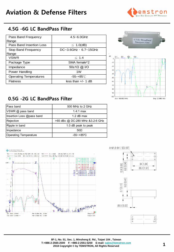
4.5~6.0GHz
Pass Band Insertion Loss ≦ 1.0(dB)
Stop Band Frequency
Range
DC~3.6GHz,6.7~15GHz
VSWR ≦ 1.4
Package Type SMA female*2
Impedance 50±1Ω @ l/O
Power Handling 1W
Operating Temperatures -55-+85℃
Flatness less than +/- 1 dB
Pass band 500 MHz to 2 GHz
VSWR @ pass band 1.4:1 max
Insertion Loss @pass band 1.2 dB max
Rejection >65 dBc @ DC-280 MHz &3.2-6 GHz
Ripple in band 1.0 dB peak to peak
Impedance 50Ω
Operating Temperature -55~+85℃
4.5G -6G LC BandPass Filter
0.5G -2G LC BandPass Filter
Broadband BP Filters
2
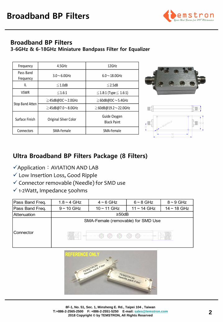
Ultra Broadband BP Filters Package (8 Filters)
8F-1, No. 51, Sec. 1, Minsheng E. Rd., Taipei 104 , Taiwan
T:+886-2-2565-2500 F: +886-2-2551-5250 E-mail: [email protected]
2018 Copyright © by TEMSTRON, All Rights Reserved
Broadband BP Filters 3-6GHz & 6-18GHz Miniature Bandpass Filter for Equalizer
Frequency 4.5GHz 12GHz
Pass Band
Frequency3.0~6.0GHz 6.0~18.0GHz
IL ≦1.0dB ≦2.5dB
VSWR ≦1.6:1 ≦1.8:1 (Type≦ 1.6:1)
≧45dB@DC~2.0GHz ≧60dB@DC~5.4GHz
≧[email protected]~8.0GHz ≧[email protected]~22.0GHz
Surface Finish Original Silver ColorGuide Oxygen
Black Paint
Connectors SMA-Female SMA-Female
Stop Band Atten
Pass Band Freq. 1.8~4 GHz 4~6 GHz 6~8 GHz 8~9 GHz
Pass Band Freq. 9~10 GHz 10~11 GHz 11~14 GHz 14~18 GHz
Attenuation ≥50dB
SMA-Female (removable) for SMD Use
Connector
Application:AVIATION AND LAB
Low Insertion Loss, Good Ripple
Connector removable (Needle) for SMD use
1-2Watt, Impedance 50ohms
3
DECT Filtersand
8F-1, No. 51, Sec. 1, Minsheng E. Rd., Taipei 104 , Taiwan
T:+886-2-2565-2500 F: +886-2-2551-5250 E-mail: [email protected]
2018 Copyright © by TEMSTRON, All Rights Reserved
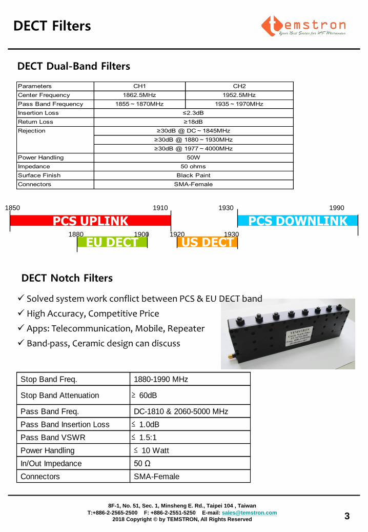
1850 1910 1930 1990
PCS UPLINK PCS DOWNLINK
EU DECT US DECT 1880 1900 1920 1930
Parameters CH1 CH2
Center Frequency 1862.5MHz 1952.5MHz
Pass Band Frequency 1855~1870MHz 1935~1970MHz
Insertion Loss
Return Loss
Power Handling
Impedance
Surface Finish
Connectors
Black Paint
SMA-Female
≤2.3dB
≥18dB
Rejection ≥30dB @ DC~1845MHz
≥30dB @ 1880~1930MHz
≥30dB @ 1977~4000MHz
50W
50 ohms
DECT Dual-Band Filters
DECT Notch Filters
Solved system work conflict between PCS & EU DECT band
High Accuracy, Competitive Price
Apps: Telecommunication, Mobile, Repeater
Band-pass, Ceramic design can discuss
Stop Band Freq. 1880-1990 MHz
Stop Band Attenuation ≥ 60dB
Pass Band Freq. DC-1810 & 2060-5000 MHz
Pass Band Insertion Loss ≤ 1.0dB
Pass Band VSWR ≤ 1.5:1
Power Handling ≤ 10 Watt
In/Out Impedance 50 Ω
Connectors SMA-Female
4
FM & UMTS & GSM Filters
IF Covert Filter
and
8F-1, No. 51, Sec. 1, Minsheng E. Rd., Taipei 104 , Taiwan
T:+886-2-2565-2500 F: +886-2-2551-5250 E-mail: [email protected]
2018 Copyright © by TEMSTRON, All Rights Reserved
Band-Pass FM Band UMTS Band GSM Band
Pass Band 88-108MHz 1920-2170MHz 880-960MHz
Insertion Loss 2.2dB 2.0dB 2.0dB
Rejection>30dB @20M-78M
>30dB @115M-3000M
>40dB @20M-1820M
>40dB @2270M-3000M
>30dB @20M-845M
>30dB @995M-3000M
Band-Stop FM Band UMTS Band GSM Band
Stop Band 88-108MHz 1920-2170MHz 880-960MHz
Stop Band Loss >30dB >25dB >30dB
Pass Band Loss<2dB @20M-78M
<2dB @115M-1800M
<2dB @20M-1820M
<2dB @2270M-3000M
<2dB @20M-845M
<2dB @995M-2000M
Power
Impedance
Connector
> 1Watt
50 ohm
Input/Output: SMA-Female
FM & UMTS & GSM Filters
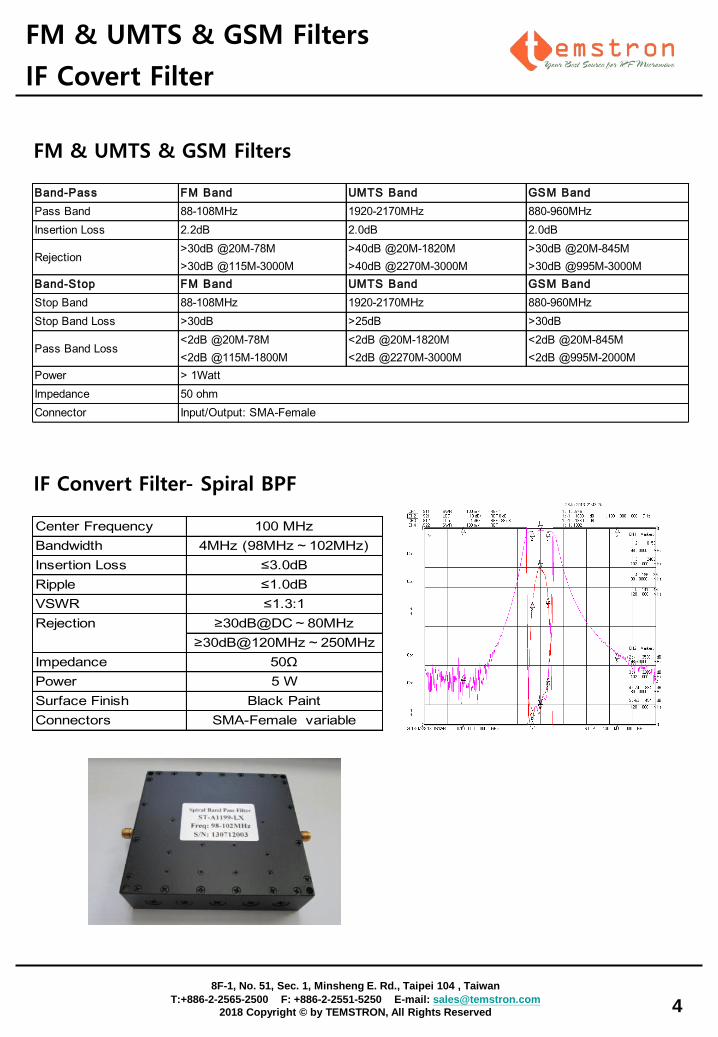
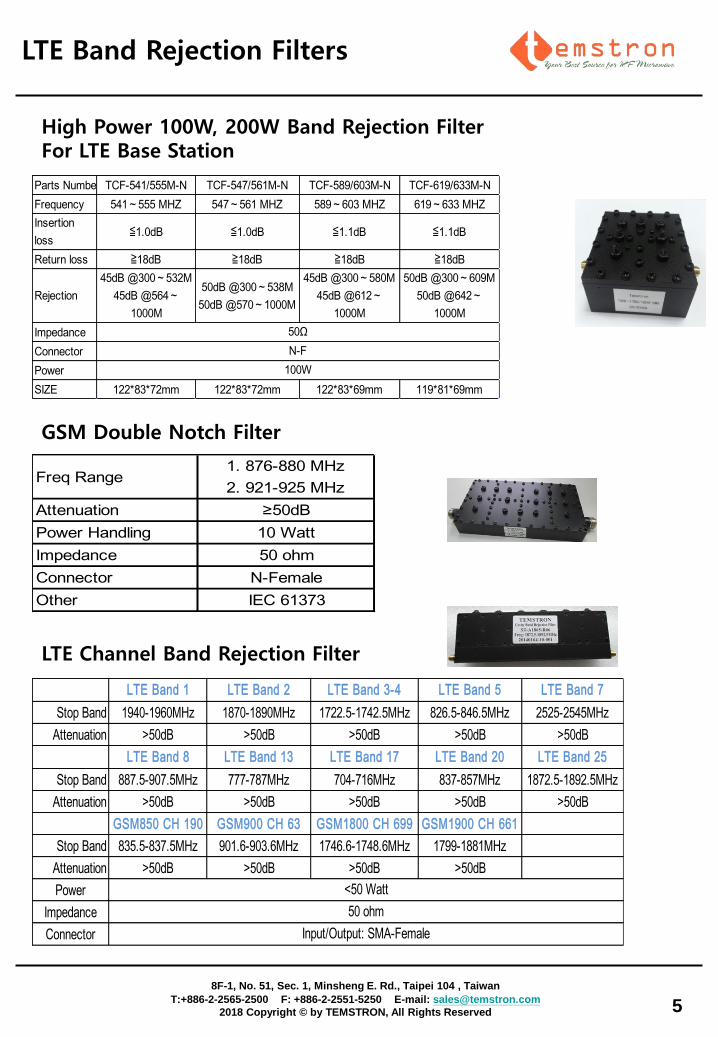
IF Convert Filter- Spiral BPF
Center Frequency 100 MHz
Bandwidth 4MHz (98MHz~102MHz)
Insertion Loss ≤3.0dB
Ripple ≤1.0dB
VSWR ≤1.3:1
≥30dB@DC~80MHz
≥30dB@120MHz~250MHz
Impedance 50Ω
Power 5 W
Surface Finish Black Paint
Connectors SMA-Female variable
Rejection
LTE Channel Band Rejection Filter
LTE Band Rejection Filters and
5
8F-1, No. 51, Sec. 1, Minsheng E. Rd., Taipei 104 , Taiwan
T:+886-2-2565-2500 F: +886-2-2551-5250 E-mail: [email protected]
2018 Copyright © by TEMSTRON, All Rights Reserved
LTE Band 1 LTE Band 2 LTE Band 3-4 LTE Band 5 LTE Band 7
Stop Band 1940-1960MHz 1870-1890MHz 1722.5-1742.5MHz 826.5-846.5MHz 2525-2545MHz
Attenuation >50dB >50dB >50dB >50dB >50dB
LTE Band 8 LTE Band 13 LTE Band 17 LTE Band 20 LTE Band 25
Stop Band 887.5-907.5MHz 777-787MHz 704-716MHz 837-857MHz 1872.5-1892.5MHz
Attenuation >50dB >50dB >50dB >50dB >50dB
GSM850 CH 190 GSM900 CH 63 GSM1800 CH 699 GSM1900 CH 661
Stop Band 835.5-837.5MHz 901.6-903.6MHz 1746.6-1748.6MHz 1799-1881MHz
Attenuation >50dB >50dB >50dB >50dB
Power
Impedance
Connector
<50 Watt
50 ohm
Input/Output: SMA-Female
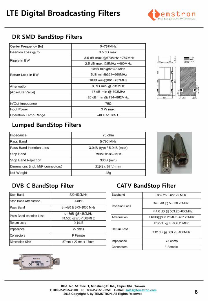
High Power 100W, 200W Band Rejection Filter For LTE Base Station
Parts Number TCF-541/555M-N TCF-547/561M-N TCF-589/603M-N TCF-619/633M-N
Frequency 541~555 MHZ 547~561 MHZ 589~603 MHZ 619~633 MHZ
Insertion
loss≦1.0dB ≦1.0dB ≦1.1dB ≦1.1dB
Return loss ≧18dB ≧18dB ≧18dB ≧18dB
Rejection
45dB @300~532M
45dB @564~
1000M
50dB @300~538M
50dB @570~1000M
45dB @300~580M
45dB @612~
1000M
50dB @300~609M
50dB @642~
1000M
Impedance
Connector
Power
SIZE 122*83*72mm 122*83*72mm 122*83*69mm 119*81*69mm
100W
50Ω
N-F
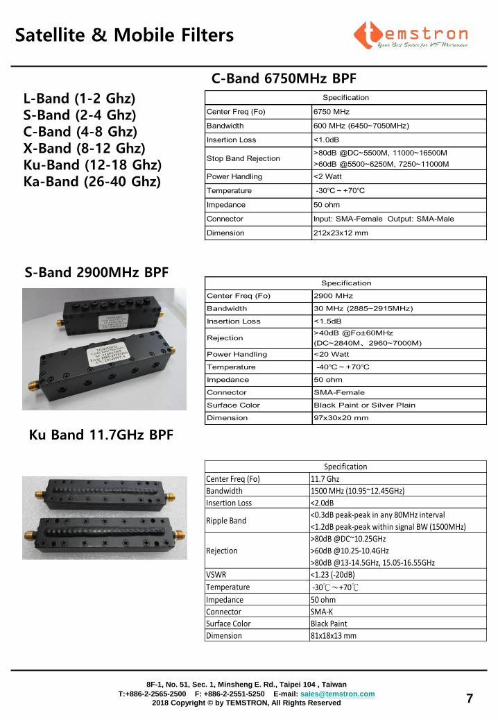
GSM Double Notch Filter
Freq Range1. 876-880 MHz
2. 921-925 MHz
Attenuation ≥50dB
Power Handling 10 Watt
Impedance 50 ohm
Connector N-Female
Other IEC 61373
6
LTE Digital Broadcasting Filters
8F-1, No. 51, Sec. 1, Minsheng E. Rd., Taipei 104 , Taiwan
T:+886-2-2565-2500 F: +886-2-2551-5250 E-mail: [email protected]
2018 Copyright © by TEMSTRON, All Rights Reserved
Stop Band 522~530MHz
Stop Band Attenuation ≥40dB
Pass Band 5~480 & 573~1000 MHz
Pass Band Insertion Loss≤1.5dB @5~480MHz
≤1.5dB @573~1000MHz
Return Loss ≥14dB
Impedance 75 ohms
Connectors F Female
Dimension Size 87mm x 27mm x 17mm
Impedance 75 ohm
Pass Band 5-790 MHz
Pass Band Insertion Loss 3.0dB (typ) / 5.0dB (max)
Stop Band 799MHz-862MHz
Stop Band Rejection 30dB (min)
Dimensions (incl. M/F connectors) 21(¢) x 57(L) mm
Net Weight 48g
Center Frequency [fo] 5~787MHz
Insertion Loss @ fo 3.5 dB max.
3.5 dB max.@670MHz ~787MHz
2.5 dB max.@5MHz ~460MHz
10dB min@5~320MHz
5dB min@321~660MHz
10dB min@661~787MHz
Attenuation 8 dB min @ 791MHz
[Absolute Value] 17 dB min @ 793MHz
20 dB min @ 794~862MHz
In/Out Impedance 75Ω
Input Power 3 W max.
Operation Temp Range -40 C to +85 C
Ripple in BW
Return Loss in BW
DR SMD BandStop Filters
DVB-C BandStop Filter CATV BandStop Filter
Lumped BandStop Filters
Stopband 352.25~487.25 MHz
≤4.0 dB @ 5~336.25MHz
≤ 4.0 dB @ 503.25~860MHz
Attenuation ≥[email protected]~487.25MHz
≥12 dB @ 5~336.25MHz
≥12 dB @ 503.25~860MHz
Impedance 75 ohms
Connectors F Female
Insertion Loss
Return Loss
Satellite & Mobile Filters Civil and
7
Center Freq (Fo) 6750 MHz
Bandwidth 600 MHz (6450~7050MHz)
Insertion Loss <1.0dB
Stop Band Rejection>80dB @DC~5500M, 11000~16500M
>60dB @5500~6250M, 7250~11000M
Power Handling <2 Watt
Temperature -30℃~+70℃
Impedance 50 ohm
Connector Input: SMA-Female Output: SMA-Male
Dimension 212x23x12 mm
Specification
C-Band 6750MHz BPF
Center Freq (Fo) 2900 MHz
Bandwidth 30 MHz (2885~2915MHz)
Insertion Loss <1.5dB
Rejection>40dB @Fo±60MHz
(DC~2840M、2960~7000M)
Power Handling <20 Watt
Temperature -40℃~+70℃
Impedance 50 ohm
Connector SMA-Female
Surface Color Black Paint or Silver Plain
Dimension 97x30x20 mm
Specification
S-Band 2900MHz BPF
L-Band (1-2 Ghz) S-Band (2-4 Ghz) C-Band (4-8 Ghz) X-Band (8-12 Ghz) Ku-Band (12-18 Ghz) Ka-Band (26-40 Ghz)
Center Freq (Fo) 11.7 Ghz
Bandwidth 1500 MHz (10.95~12.45GHz)
Insertion Loss <2.0dB
Ripple Band<0.3dB peak-peak in any 80MHz interval
<1.2dB peak-peak within signal BW (1500MHz)
Rejection
>80dB @DC~10.25GHz
>60dB @10.25-10.4GHz
>80dB @13-14.5GHz, 15.05-16.55GHz
VSWR <1.23 (-20dB)
Temperature -30℃~+70℃
Impedance 50 ohm
Connector SMA-K
Surface Color Black Paint
Dimension 81x18x13 mm
Specification
Ku Band 11.7GHz BPF
8F-1, No. 51, Sec. 1, Minsheng E. Rd., Taipei 104 , Taiwan
T:+886-2-2565-2500 F: +886-2-2551-5250 E-mail: [email protected]
2018 Copyright © by TEMSTRON, All Rights Reserved

Model3dB
Cut off(GHz)
1dB
Pass Band(GHz)
Insertion
Loss(dB)VSWR
Stop Band Rejection
(dB@GHz)
Power
Handling(W)Connectors
Size
LxWxH(mm)
TA0138-HS 1 1.1~4 ≤1.0 ≤2.0 ≥45@DC~0.85 (Type50) 15 SMA-F 71x40x10
TA0139-HS 2 2.2~12 ≤1.0 ≤2.0 ≥45@DC~1.7 (Type50) 15 SMA-F 38x34x10
TA0140-HS 3 3.3~12 ≤1.0 ≤2.0 ≥45@DC~2.55 (Type50) 15 SMA-F 35x31x10
TA0141-HS 4 4.4~12 ≤1.0 ≤2.0 ≥45@DC~3.4 (Type50) 15 SMA-F 34x25x10
TS-A0107-HS 5 5.5~16 ≤1.0 ≤2.0 ≥45@DC~4.25 (Type50) 15 SMA-F 26x25x10
TA0072-HS 6 6.6~18 ≤1.0 ≤2.0 ≥45@DC~5.1 (Type50) 15 SMA-F 29x28x10
TA0142-HS 7 7.7~18 ≤1.0 ≤2.0 ≥45@DC~5.95 (Type50) 15 SMA-F 29x23x10
TA0143-HS 8 8.8~18 ≤1.0 ≤2.0 ≥45@DC~6.8 (Type50) 15 SMA-F 23x25x10
TA0144-HS 9 9.9~18 ≤1.0 ≤2.0 ≥45@DC~7.65 (Type50) 15 SMA-F 25x24x10
TA0145-HS 10 11~18 ≤1.0 ≤2.0 ≥45@DC~8.5 (Type50) 15 SMA-F 25x23x10
TA0146-HS 11 12.1~18 ≤1.0 ≤2.0 ≥45@DC~9.35 (Type50) 15 SMA-F 24x22x10
TA0147-HS 12 13.2~18 ≤1.0 ≤2.0 ≥45@DC~10.2 (Type50) 15 SMA-F 24x21x10
TA0034-HS ---- 2~18 ≤1.0 ≤2.0 ≥50@DC~1.5 (Type60) 15 SMA-F 44x17x10
TA0223-HS ---- 3~18 ≤1.0 ≤2.0 ≥65@DC~2 (Type70) 15 SMA-F 31x17x10
TA0225-HS ---- 4~18 ≤1.0 ≤2.0 ≥40@DC~3 (Type45) 15 SMA-F 28x17x10
TA0074-HS ---- 1.5~13 ≤1.0 ≤2.0 ≥50@DC~1 (Type65) 15 SMA-F 53x20x10
TA0233-HS ---- 4~18 ≤1.0 ≤2.0 ≥40@DC~2.5 15 SMA-F 22x17x10
High Pass Filter Series
Low Pass Filter Series
Model
3dB
Cut off(GHz)
1dB
Pass Band(GHz)
Insertion
Loss(dB) VSWR
Stop Band Rejection
(dB@GHz)
Power
Handling(W) Connectors
Size
LxWxH(mm)
TA0148-LS 1 DC~0.9 ≤1.0 ≤2.0 ≥[email protected]~4 (Type50) 15 SMA-F 120x41x10
TA0098-LS 2 DC~1.8 ≤1.0 ≤2.0 ≥[email protected]~6 (Type50) 15 SMA-F 53x36x10
TA0106-LS 3 DC~2.7 ≤1.0 ≤2.0 ≥[email protected]~8 (Type50) 15 SMA-F 41x34x10
TA0149-LS 4 DC~3.6 ≤1.0 ≤2.0 ≥[email protected]~10 (Type50) 15 SMA-F 39x27x10
TA0150-LS 5 DC~4.5 ≤1.0 ≤2.0 ≥[email protected]~12 (Type50) 15 SMA-F 35x24x10
TA0137-LS 6 DC~5.4 ≤1.0 ≤2.0 ≥[email protected]~14 (Type50) 15 SMA-F 35x22x10
TA0151-LS 7 DC~6.3 ≤1.0 ≤2.0 ≥45@8~15 (Type50) 15 SMA-F 33x22x10
TA0152-LS 8 DC~7.2 ≤1.0 ≤2.0 ≥[email protected]~16 (Type50) 15 SMA-F 33x21x10
TA0079-LS 9 DC~8.1 ≤1.0 ≤2.0 ≥[email protected]~16.5 (Type50) 15 SMA-F 25x19x10
TA0153-LS 10 DC~9 ≤1.0 ≤2.0 ≥[email protected]~17 (Type50) 15 SMA-F 24x18.5x10
TA0154-LS 11 DC~9.9 ≤1.0 ≤2.0 ≥[email protected]~17.5 (Type50) 15 SMA-F 23x18.5x10
TA0155-LS 12 DC~10.8 ≤1.0 ≤2.0 ≥[email protected]~18 (Type50) 15 SMA-F 20x18x10
TA0229-LS 13 DC~11.7 ≤1.0 ≤2.0 ≥45@15~19 (Type50) 15 SMA-F 20x17.5x10
TA0224-LS 14 DC~12.6 ≤1.0 ≤2.0 ≥[email protected]~20 (Type50) 15 SMA-F 19x17.5x10
TA0173-LS ---- DC~2 ≤1.0 ≤2.0 ≥[email protected]~13 (Type55) 15 SMA-F 83x35x10
TA0071-LS ---- DC~2.75 ≤1.6 ≤1.7 ≥40@3~8.5 (Type45) 15 SMA-F 59x39x10
Suspended Substrate Stripline Filters
8
8F-1, No. 51, Sec. 1, Minsheng E. Rd., Taipei 104 , Taiwan
T:+886-2-2565-2500 F: +886-2-2551-5250 E-mail: [email protected]
2018 Copyright © by TEMSTRON, All Rights Reserved
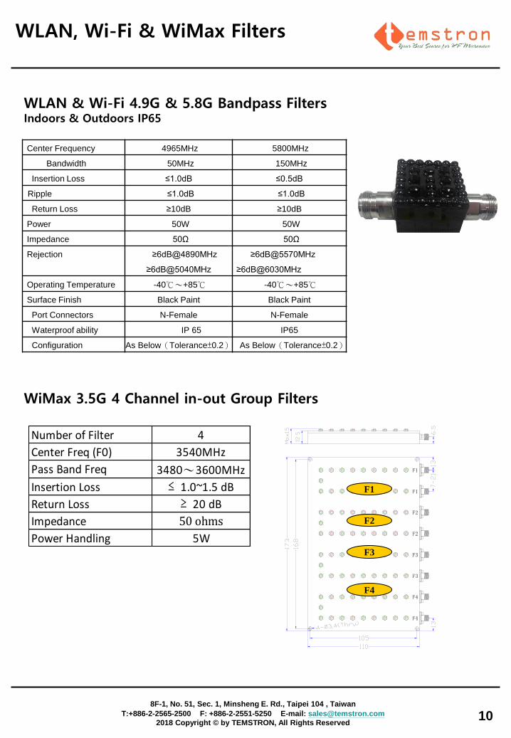
Satellite & D-TV (ch1-12) Channel BP Filters
Channel Pass Band Channel Pass Band
CH1 30-40 MHz CH7 108-157 MHz
CH2 40-50 MHz CH8 147-230 MHz
CH3 50-60 MHz CH9 220-290 MHz
CH4 60-70 MHz CH10 280-345 MHz
CH5 70-80 MHz CH11 335-405 MHz
CH6 80-88 MHz CH12 395-512 MHz
IL
Ripple
VSWR
Rejection
Power
I/O PORT
Dimension
VHF-FM K-WNW
I Watt
50 ohm Feed
39*10.5*8 mm
≦ 4.0 dB
≦ 1.2 dB
≦ 1.5 : 1
≧ -40dB
TV Channel Filters
9
8F-1, No. 51, Sec. 1, Minsheng E. Rd., Taipei 104 , Taiwan
T:+886-2-2565-2500 F: +886-2-2551-5250 E-mail: [email protected]
2018 Copyright © by TEMSTRON, All Rights Reserved
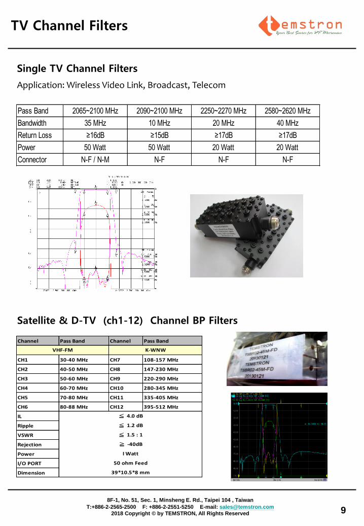
Pass Band 2065~2100 MHz 2090~2100 MHz 2250~2270 MHz 2580~2620 MHz
Bandwidth 35 MHz 10 MHz 20 MHz 40 MHz
Return Loss ≥16dB ≥15dB ≥17dB ≥17dB
Power 50 Watt 50 Watt 20 Watt 20 Watt
Connector N-F / N-M N-F N-F N-F
Application: Wireless Video Link, Broadcast, Telecom
Single TV Channel Filters
WLAN, Wi-Fi & WiMax Filters
10
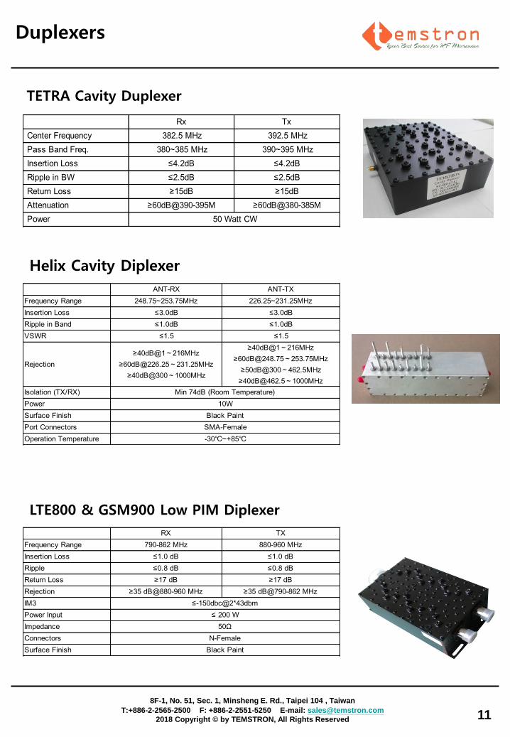
Center Frequency 4965MHz 5800MHz
Bandwidth 50MHz 150MHz
Insertion Loss ≤1.0dB ≤0.5dB
Ripple ≤1.0dB ≤1.0dB
Return Loss ≥10dB ≥10dB
Power 50W 50W
Impedance 50Ω 50Ω
Rejection ≥6dB@4890MHz
≥6dB@5040MHz
≥6dB@5570MHz
≥6dB@6030MHz
Operating Temperature -40℃~+85℃ -40℃~+85℃
Surface Finish Black Paint Black Paint
Port Connectors N-Female N-Female
Waterproof ability IP 65 IP65
Configuration As Below(Tolerance±0.2) As Below(Tolerance±0.2)
WLAN & Wi-Fi 4.9G & 5.8G Bandpass Filters Indoors & Outdoors IP65
8F-1, No. 51, Sec. 1, Minsheng E. Rd., Taipei 104 , Taiwan
T:+886-2-2565-2500 F: +886-2-2551-5250 E-mail: [email protected]
2018 Copyright © by TEMSTRON, All Rights Reserved
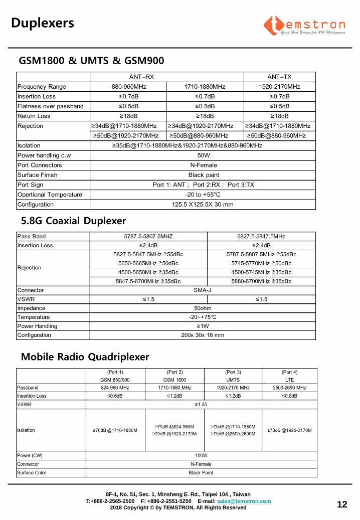
WiMax 3.5G 4 Channel in-out Group Filters
Number of Filter 4
Center Freq (F0) 3540MHz
Pass Band Freq 3480~3600MHz
Insertion Loss ≤ 1.0~1.5 dB
Return Loss ≥ 20 dB
Impedance 50 ohms
Power Handling 5W
F1
F1
F2
F2
F3
F3
F4
F4
F1
F2
F3
F4
Duplexers
11
LTE800 & GSM900 Low PIM Diplexer
Rx Tx
Center Frequency 382.5 MHz 392.5 MHz
Pass Band Freq. 380~385 MHz 390~395 MHz
Insertion Loss ≤4.2dB ≤4.2dB
Ripple in BW ≤2.5dB ≤2.5dB
Return Loss ≥15dB ≥15dB
Attenuation ≥60dB@390-395M ≥60dB@380-385M
Power 50 Watt CW
TETRA Cavity Duplexer
ANT-RX ANT-TX
Frequency Range 248.75~253.75MHz 226.25~231.25MHz
Insertion Loss ≤3.0dB ≤3.0dB
Ripple in Band ≤1.0dB ≤1.0dB
VSWR ≤1.5 ≤1.5
Rejection
≥40dB@1~216MHz
≥[email protected]~231.25MHz
≥40dB@300~1000MHz
≥40dB@1~216MHz
≥[email protected]~253.75MHz
≥50dB@300~462.5MHz
≥[email protected]~1000MHz
Isolation (TX/RX)
Power
Surface Finish
Port Connectors
Operation Temperature -30℃~+85℃
Min 74dB (Room Temperature)
10W
Black Paint
SMA-Female
Helix Cavity Diplexer
8F-1, No. 51, Sec. 1, Minsheng E. Rd., Taipei 104 , Taiwan
T:+886-2-2565-2500 F: +886-2-2551-5250 E-mail: [email protected]
2018 Copyright © by TEMSTRON, All Rights Reserved
RX TX
Frequency Range 790-862 MHz 880-960 MHz
Insertion Loss ≤1.0 dB ≤1.0 dB
Ripple ≤0.8 dB ≤0.8 dB
Return Loss ≥17 dB ≥17 dB
Rejection ≥35 dB@880-960 MHz ≥35 dB@790-862 MHz
IM3
Power Input
Impedance
Connectors
Surface Finish Black Paint
≤-150dbc@2*43dbm
≤ 200 W
50Ω
N-Female
Duplexers
12
8F-1, No. 51, Sec. 1, Minsheng E. Rd., Taipei 104 , Taiwan
T:+886-2-2565-2500 F: +886-2-2551-5250 E-mail: [email protected]
2018 Copyright © by TEMSTRON, All Rights Reserved
ANT--TX
Frequency Range 880-960MHz 1710-1880MHz 1920-2170MHz
Insertion Loss ≤0.7dB ≤0.7dB ≤0.7dB
Flatness over passband ≤0.5dB ≤0.5dB ≤0.5dB
Return Loss ≥18dB ≥18dB ≥18dB
≥34dB@1710-1880MHz ≥34dB@1920-2170MHz ≥34dB@1710-1880MHz
≥50dB@1920-2170MHz ≥50dB@880-960MHz ≥50dB@880-960MHz
Isolation
Power handling c.w
Port Connectors
Surface Finish
Port Sign
Opertional Temperature
Configuration
Port 1: ANT ; Port 2:RX ; Port 3:TX
-20 to +55°C
125.5 X125.5X 30 mm
ANT--RX
Rejection
≥35dB@1710-1880MHz&1920-2170MHz&880-960MHz
50W
N-Female
Black paint
GSM1800 & UMTS & GSM900
Pass Band 5787.5-5807.5MHZ 5827.5-5847.5MHz
Insertion Loss ≤2.4dB ≤2.4dB
5827.5-5847.5MHz ≧55dBc 5787.5-5807.5MHz ≧55dBc
5650-5665MHz ≧50dBc 5745-5770MHz ≧50dBc
4500-5650MHz ≧35dBc 4500-5745MHz ≧35dBc
5847.5-6700MHz ≧35dBc 5880-6700MHz ≧35dBc
Connector
VSWR ≤1.5 ≤1.5
Impedance
Temperature
Power Handling
Configuration
SMA-J
50ohm
-20~+75℃
≥1W
200x 30x 16 mm
Rejection
5.8G Coaxial Duplexer
(Port 1)
GSM 850/900
(Port 2)
GSM 1800
(Port 3)
UMTS
(Port 4)
LTE
Passband 824-960 MHz 1710-1880 MHz 1920-2170 MHz 2500-2690 MHz
Insertion Loss ≤0.6dB ≤1.2dB ≤1.2dB ≤0.8dB
VSWR
Isolation ≥70dB @1710-1880M≥70dB @824-960M
≥70dB @1920-2170M
≥70dB @1710-1880M
≥70dB @2500-2690M≥70dB @1920-2170M
Power (CW)
Connector
Surface Color
≤1.35
100W
N-Female
Black Paint
Mobile Radio Quadriplexer
13
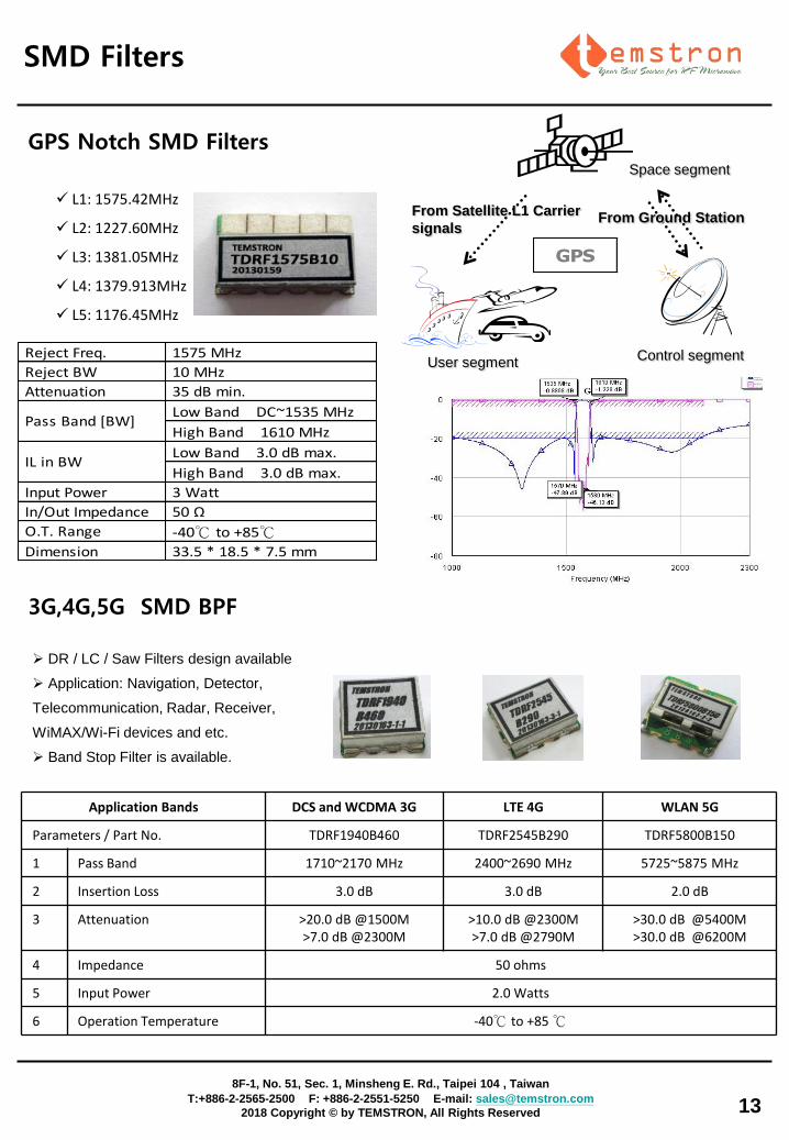
Reject Freq. 1575 MHz
Reject BW 10 MHz
Attenuation 35 dB min.
Low Band DC~1535 MHz
High Band 1610 MHz
Low Band 3.0 dB max.
High Band 3.0 dB max.
Input Power 3 Watt
In/Out Impedance 50 Ω
O.T. Range -40℃ to +85℃
Dimension 33.5 * 18.5 * 7.5 mm
IL in BW
Pass Band [BW]
L1: 1575.42MHz
L2: 1227.60MHz
L3: 1381.05MHz
L4: 1379.913MHz
L5: 1176.45MHz
Space segment
Control segment User segment
From Ground Station From Satellite L1 Carrier
signals
GPS
SMD Filters
DR / LC / Saw Filters design available
Application: Navigation, Detector,
Telecommunication, Radar, Receiver,
WiMAX/Wi-Fi devices and etc.
Band Stop Filter is available.
Application Bands DCS and WCDMA 3G LTE 4G WLAN 5G
Parameters / Part No. TDRF1940B460 TDRF2545B290 TDRF5800B150
1 Pass Band 1710~2170 MHz 2400~2690 MHz 5725~5875 MHz
2 Insertion Loss 3.0 dB 3.0 dB 2.0 dB
3 Attenuation >20.0 dB @1500M >7.0 dB @2300M
>10.0 dB @2300M >7.0 dB @2790M
>30.0 dB @5400M >30.0 dB @6200M
4 Impedance 50 ohms
5 Input Power 2.0 Watts
6 Operation Temperature -40℃ to +85 ℃
3G,4G,5G SMD BPF
GPS Notch SMD Filters
8F-1, No. 51, Sec. 1, Minsheng E. Rd., Taipei 104 , Taiwan
T:+886-2-2565-2500 F: +886-2-2551-5250 E-mail: [email protected]
2018 Copyright © by TEMSTRON, All Rights Reserved
14
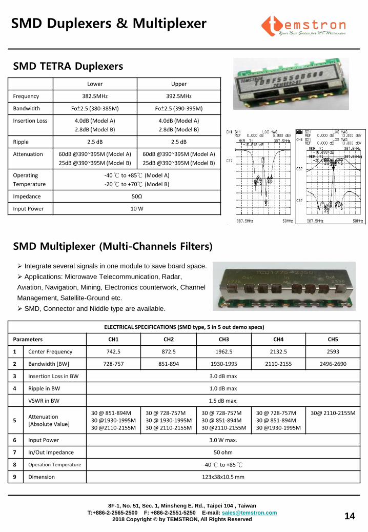
Integrate several signals in one module to save board space.
Applications: Microwave Telecommunication, Radar,
Aviation, Navigation, Mining, Electronics counterwork, Channel
Management, Satellite-Ground etc.
SMD, Connector and Niddle type are available.
ELECTRICAL SPECIFICATIONS (SMD type, 5 in 5 out demo specs)
Parameters CH1 CH2 CH3 CH4 CH5
1 Center Frequency 742.5 872.5 1962.5 2132.5 2593
2 Bandwidth [BW] 728-757 851-894 1930-1995 2110-2155 2496-2690
3 Insertion Loss in BW 3.0 dB max
4 Ripple in BW 1.0 dB max
VSWR in BW 1.5 dB max.
5 Attenuation [Absolute Value]
30 @ 851-894M 30 @1930-1995M 30 @2110-2155M
30 @ 728-757M 30 @ 1930-1995M 30 @ 2110-2155M
30 @ 728-757M 30 @ 851-894M 30 @2110-2155M
30 @ 728-757M 30 @ 851-894M 30 @1930-1995M
30@ 2110-2155M
6 Input Power 3.0 W max.
7 In/Out Impedance 50 ohm
8 Operation Temperature -40 ℃ to +85 ℃
9 Dimension 123x38x10.5 mm
SMD Multiplexer (Multi-Channels Filters)
Lower Upper
Frequency 382.5MHz 392.5MHz
Bandwidth Fo±2.5 (380-385M) Fo±2.5 (390-395M)
Insertion Loss 4.0dB (Model A)
2.8dB (Model B)
4.0dB (Model A)
2.8dB (Model B)
Ripple 2.5 dB 2.5 dB
Attenuation 60dB @390~395M (Model A)
25dB @390~395M (Model B)
60dB @390~395M (Model A)
25dB @390~395M (Model B)
Operating
Temperature
-40 ℃ to +85℃ (Model A)
-20 ℃ to +70℃ (Model B)
Impedance 50Ω
Input Power 10 W
SMD Duplexers & Multiplexer
SMD TETRA Duplexers
8F-1, No. 51, Sec. 1, Minsheng E. Rd., Taipei 104 , Taiwan
T:+886-2-2565-2500 F: +886-2-2551-5250 E-mail: [email protected]
2018 Copyright © by TEMSTRON, All Rights Reserved
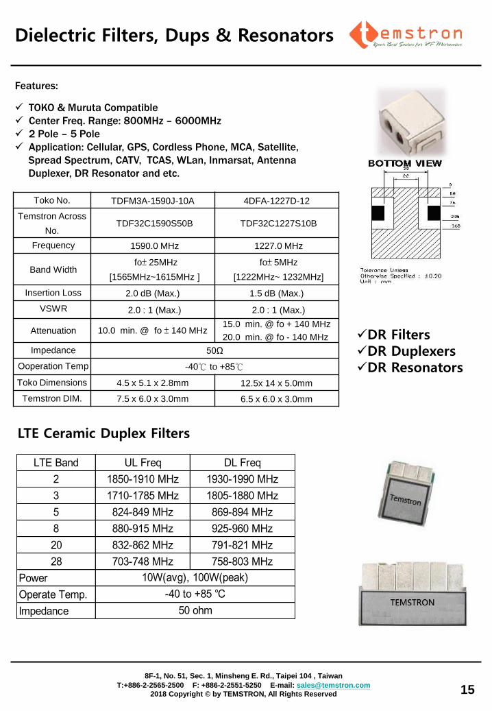
Features:
TOKO & Muruta Compatible
Center Freq. Range: 800MHz – 6000MHz
2 Pole – 5 Pole
Application: Cellular, GPS, Cordless Phone, MCA, Satellite,
Spread Spectrum, CATV, TCAS, WLan, Inmarsat, Antenna
Duplexer, DR Resonator and etc.
Toko No. TDFM3A-1590J-10A 4DFA-1227D-12
Temstron Across
No. TDF32C1590S50B TDF32C1227S10B
Frequency 1590.0 MHz 1227.0 MHz
Band Width fo± 25MHz
[1565MHz~1615MHz ]
fo± 5MHz
[1222MHz~ 1232MHz]
Insertion Loss 2.0 dB (Max.) 1.5 dB (Max.)
VSWR 2.0 : 1 (Max.) 2.0 : 1 (Max.)
Attenuation 10.0 min. @ fo ± 140 MHz 15.0 min. @ fo + 140 MHz
20.0 min. @ fo - 140 MHz
Impedance 50Ω
Ooperation Temp -40℃ to +85℃
Toko Dimensions 4.5 x 5.1 x 2.8mm 12.5x 14 x 5.0mm
Temstron DIM. 7.5 x 6.0 x 3.0mm 6.5 x 6.0 x 3.0mm
DR Filters DR Duplexers DR Resonators
Dielectric Filters, Dups & Resonators
15
8F-1, No. 51, Sec. 1, Minsheng E. Rd., Taipei 104 , Taiwan
T:+886-2-2565-2500 F: +886-2-2551-5250 E-mail: [email protected]
2018 Copyright © by TEMSTRON, All Rights Reserved
LTE Band UL Freq DL Freq
2 1850-1910 MHz 1930-1990 MHz
3 1710-1785 MHz 1805-1880 MHz
5 824-849 MHz 869-894 MHz
8 880-915 MHz 925-960 MHz
20 832-862 MHz 791-821 MHz
28 703-748 MHz 758-803 MHz
Power
Operate Temp.
Impedance 50 ohm
10W(avg), 100W(peak)
-40 to +85 ℃
LTE Ceramic Duplex Filters
16
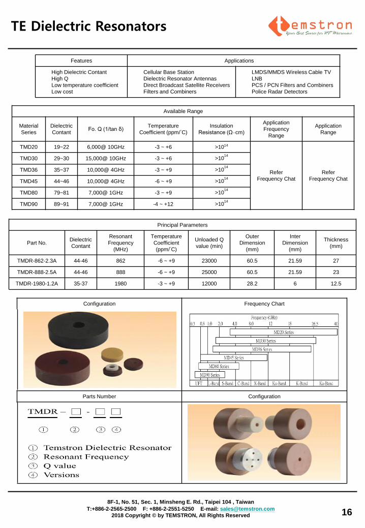
Features Applications
High Dielectric Contant
High Q
Low temperature coefficient
Low cost
Cellular Base Station
Dielectric Resonator Antennas
Direct Broadcast Satellite Receivers
Filters and Combiners
LMDS/MMDS Wireless Cable TV
LNB
PCS / PCN Filters and Combiners
Police Radar Detectors
Configuration Frequency Chart
Parts Number Configuration
Available Range
Material
Series
Dielectric
Contant Fo. Q (1/tan δ)
Temperature
Coefficient (ppm/°C)
Insulation
Resistance (Ω–cm)
Application
Frequency
Range
Application
Range
TMD20 19~22 6,000@ 10GHz -3 ~ +6 >1014
Refer
Frequency Chat
Refer
Frequency Chat
TMD30 29~30 15,000@ 10GHz -3 ~ +6 >1014
TMD36 35~37 10,000@ 4GHz -3 ~ +9 >1014
TMD45 44~46 10,000@ 4GHz -6 ~ +9 >1014
TMD80 79~81 7,000@ 1GHz -3 ~ +9 >1014
TMD90 89~91 7,000@ 1GHz -4 ~ +12 >1014
Principal Parameters
Part No. Dielectric
Contant
Resonant
Frequency
(MHz)
Temperature
Coefficient
(ppm/°C)
Unloaded Q
value (min)
Outer
Dimension
(mm)
Inter
Dimension
(mm)
Thickness
(mm)
TMDR-862-2.3A 44-46 862 -6 ~ +9 23000 60.5 21.59 27
TMDR-888-2.5A 44-46 888 -6 ~ +9 25000 60.5 21.59 23
TMDR-1980-1.2A 35-37 1980 -3 ~ +9 12000 28.2 6 12.5
TE Dielectric Resonators
8F-1, No. 51, Sec. 1, Minsheng E. Rd., Taipei 104 , Taiwan
T:+886-2-2565-2500 F: +886-2-2551-5250 E-mail: [email protected]
2018 Copyright © by TEMSTRON, All Rights Reserved
17
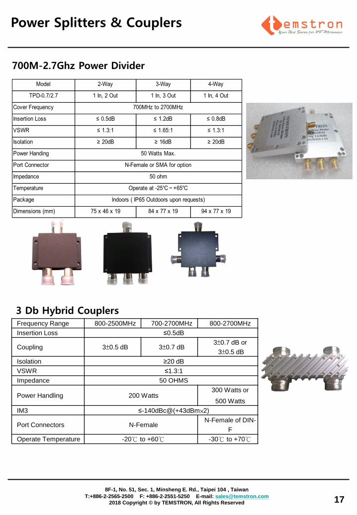
700M-2.7Ghz Power Divider
Power Splitters & Couplers
Model 2-Way 3-Way 4-Way
TPD-0.7/2.7 1 In, 2 Out 1 In, 3 Out 1 In, 4 Out
Cover Frequency
Insertion Loss ≤ 0.5dB ≤ 1.2dB ≤ 0.8dB
VSWR ≤ 1.3:1 ≤ 1.65:1 ≤ 1.3:1
Isolation ≥ 20dB ≥ 16dB ≥ 20dB
Power Handing
Port Connector
Impedance
Temperature
Package
Dimensions (mm) 75 x 46 x 19 84 x 77 x 19 94 x 77 x 19
50 ohm
Indoors ( IP65 Outdoors upon requests)
50 Watts Max.
700MHz to 2700MHz
N-Female or SMA for option
Operate at -25℃~+65℃
8F-1, No. 51, Sec. 1, Minsheng E. Rd., Taipei 104 , Taiwan
T:+886-2-2565-2500 F: +886-2-2551-5250 E-mail: [email protected]
2018 Copyright © by TEMSTRON, All Rights Reserved
Frequency Range 800-2500MHz 700-2700MHz 800-2700MHz
Insertion Loss ≤0.5dB
Coupling 3±0.5 dB 3±0.7 dB 3±0.7 dB or
3±0.5 dB
Isolation ≥20 dB
VSWR ≤1.3:1
Impedance 50 OHMS
Power Handling 200 Watts 300 Watts or
500 Watts
IM3 ≤-140dBc@(+43dBm×2)
Port Connectors N-Female N-Female of DIN-
F
Operate Temperature -20℃ to +60℃ -30℃ to +70℃
3 Db Hybrid Couplers
18
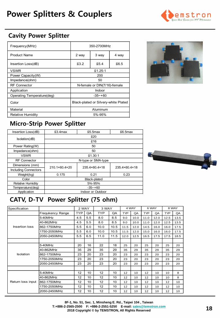
Cavity Power Splitter
Insertion Loss(dB) ≦3.4max ≦5.5max ≦6.5max
Power Rating(W)
Impedance(ohm)
VSWR
RF Connector
Dimensions (mm)
Including Connectors
Weight(kg) 0.175 0.21 0.23
Color
Relative Humidity
Temperature(deg)
Application
235.4×60.4×18 235.4×60.4×18
Isolation(dB)≧20
≧16
-35~+60
Indoor or Outdoor
50
50
≦1.30:1
N-type or SMA-type
Black-plated
5%-95%
210.1×60.4×20
Micro-Strip Power Splitter
Power Splitters & Couplers
Frequency(MHz)
Product Name 2 way 3 way 4 way
Insertion Loss(dB) ≦3.2 ≦5.4 ≦6.5
VSWR
Power Capacity(W)
Impedance(ohm)
RF Connector
Application
Operating Temperature(deg)
Color
Material
Relative Humidity
350-2700MHz
≦1.25:1
200
50
N-female or DIN(7/16)-female
Indoor
-35~+60
Black-plated or Silvery-white Plated
Aluminum
5%-95%
CATV, D-TV Power Splitter (75 ohm)
Specification
Frequkency Range TYP QA TYP QA TYP QA TYP QA TYP QA
5-40MHz 4.5 5.5 8.0 8.5 9.0 10.0 11.0 12.0 12.5 13.5
40-862MHz 4.5 5.5 8.0 8.5 9.0 10.0 11.0 12.0 12.5 13.5
862-1750MHz 5.5 6.0 10.0 10.5 11.5 12.0 14.5 16.0 16.0 17.5
1750-2050MHz 5.5 6.0 10.0 10.5 11.5 12.0 15.0 16.0 16.0 17.5
2050-2450MHz 5.5 6.5 11.0 11.5 12.0 12.5 16.5 17.5 17.5 18.5
5-40MHz 20 16 22 18 25 20 25 20 25 20
40-862MHz 35 29 35 29 35 29 35 29 35 29
862-1750MHz 23 20 23 20 23 20 23 20 23 20
1750-2050MHz 23 20 23 20 23 20 23 20 23 20
2050-2450MHz 23 20 23 20 23 20 23 20 23 20
5-40MHz 12 10 12 10 12 10 12 10 10 8
40-862MHz 12 10 12 10 12 10 12 10 10 8
862-1750MHz 12 10 12 10 12 10 12 10 12 10
1750-2050MHz 12 10 12 10 12 10 12 10 12 10
2050-2450MHz 12 10 12 10 12 10 12 10 12 10
4 WAY
SPLITTER
6 WAY
SPLITTER
8 WAY
SPLITTER
Insertion loss
2 WAY 3 WAY
Isolation
Return loss input
8F-1, No. 51, Sec. 1, Minsheng E. Rd., Taipei 104 , Taiwan
T:+886-2-2565-2500 F: +886-2-2551-5250 E-mail: [email protected]
2018 Copyright © by TEMSTRON, All Rights Reserved
Drop-in & SMD CIRCULATOR
19
8F-1, No. 51, Sec. 1, Minsheng E. Rd., Taipei 104 , Taiwan
T:+886-2-2565-2500 F: +886-2-2551-5250 E-mail: [email protected]
2018 Copyright © by TEMSTRON, All Rights Reserved
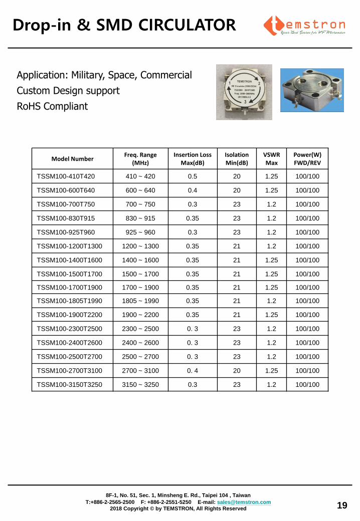
Application: Military, Space, Commercial
Custom Design support
RoHS Compliant
Model Number Freq. Range
(MHz) Insertion Loss
Max(dB) Isolation Min(dB)
VSWR Max
Power(W) FWD/REV
TSSM100-410T420 410 ~ 420 0.5 20 1.25 100/100
TSSM100-600T640 600 ~ 640 0.4 20 1.25 100/100
TSSM100-700T750 700 ~ 750 0.3 23 1.2 100/100
TSSM100-830T915 830 ~ 915 0.35 23 1.2 100/100
TSSM100-925T960 925 ~ 960 0.3 23 1.2 100/100
TSSM100-1200T1300 1200 ~ 1300 0.35 21 1.2 100/100
TSSM100-1400T1600 1400 ~ 1600 0.35 21 1.25 100/100
TSSM100-1500T1700 1500 ~ 1700 0.35 21 1.25 100/100
TSSM100-1700T1900 1700 ~ 1900 0.35 21 1.25 100/100
TSSM100-1805T1990 1805 ~ 1990 0.35 21 1.2 100/100
TSSM100-1900T2200 1900 ~ 2200 0.35 21 1.25 100/100
TSSM100-2300T2500 2300 ~ 2500 0. 3 23 1.2 100/100
TSSM100-2400T2600 2400 ~ 2600 0. 3 23 1.2 100/100
TSSM100-2500T2700 2500 ~ 2700 0. 3 23 1.2 100/100
TSSM100-2700T3100 2700 ~ 3100 0. 4 20 1.25 100/100
TSSM100-3150T3250 3150 ~ 3250 0.3 23 1.2 100/100
Drop-in & SMD ISOLATOR
20
8F-1, No. 51, Sec. 1, Minsheng E. Rd., Taipei 104 , Taiwan
T:+886-2-2565-2500 F: +886-2-2551-5250 E-mail: [email protected]
2018 Copyright © by TEMSTRON, All Rights Reserved
Model Number Freq. Range
(MHz) Insertion Loss
Max(dB) Isolation Min(dB)
VSWR Max
Power(W) FWD/REV
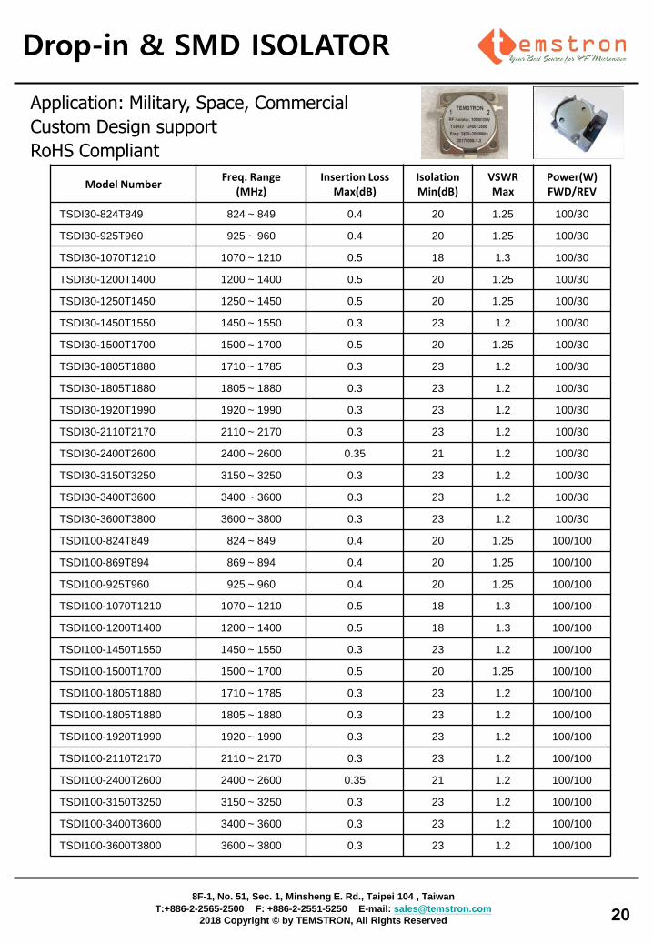
TSDI30-824T849 824 ~ 849 0.4 20 1.25 100/30
TSDI30-925T960 925 ~ 960 0.4 20 1.25 100/30
TSDI30-1070T1210 1070 ~ 1210 0.5 18 1.3 100/30
TSDI30-1200T1400 1200 ~ 1400 0.5 20 1.25 100/30
TSDI30-1250T1450 1250 ~ 1450 0.5 20 1.25 100/30
TSDI30-1450T1550 1450 ~ 1550 0.3 23 1.2 100/30
TSDI30-1500T1700 1500 ~ 1700 0.5 20 1.25 100/30
TSDI30-1805T1880 1710 ~ 1785 0.3 23 1.2 100/30
TSDI30-1805T1880 1805 ~ 1880 0.3 23 1.2 100/30
TSDI30-1920T1990 1920 ~ 1990 0.3 23 1.2 100/30
TSDI30-2110T2170 2110 ~ 2170 0.3 23 1.2 100/30
TSDI30-2400T2600 2400 ~ 2600 0.35 21 1.2 100/30
TSDI30-3150T3250 3150 ~ 3250 0.3 23 1.2 100/30
TSDI30-3400T3600 3400 ~ 3600 0.3 23 1.2 100/30
TSDI30-3600T3800 3600 ~ 3800 0.3 23 1.2 100/30
TSDI100-824T849 824 ~ 849 0.4 20 1.25 100/100
TSDI100-869T894 869 ~ 894 0.4 20 1.25 100/100
TSDI100-925T960 925 ~ 960 0.4 20 1.25 100/100
TSDI100-1070T1210 1070 ~ 1210 0.5 18 1.3 100/100
TSDI100-1200T1400 1200 ~ 1400 0.5 18 1.3 100/100
TSDI100-1450T1550 1450 ~ 1550 0.3 23 1.2 100/100
TSDI100-1500T1700 1500 ~ 1700 0.5 20 1.25 100/100
TSDI100-1805T1880 1710 ~ 1785 0.3 23 1.2 100/100
TSDI100-1805T1880 1805 ~ 1880 0.3 23 1.2 100/100
TSDI100-1920T1990 1920 ~ 1990 0.3 23 1.2 100/100
TSDI100-2110T2170 2110 ~ 2170 0.3 23 1.2 100/100
TSDI100-2400T2600 2400 ~ 2600 0.35 21 1.2 100/100
TSDI100-3150T3250 3150 ~ 3250 0.3 23 1.2 100/100
TSDI100-3400T3600 3400 ~ 3600 0.3 23 1.2 100/100
TSDI100-3600T3800 3600 ~ 3800 0.3 23 1.2 100/100
Application: Military, Space, Commercial
Custom Design support
RoHS Compliant
Amplifiers
21
8F-1, No. 51, Sec. 1, Minsheng E. Rd., Taipei 104 , Taiwan
T:+886-2-2565-2500 F: +886-2-2551-5250 E-mail: [email protected]
2018 Copyright © by TEMSTRON, All Rights Reserved
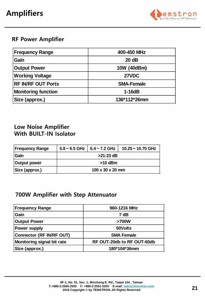
Low Noise Amplifier With BUILT-IN Isolator
Frequency Range 5.8~6.5 GHz 6.4~7.2 GHz 10.25~10.70 GHz
Gain
Output power
Size (approx.)
>21-23 dB
>10 dBm
100 x 30 x 20 mm
Frequency Range 400-450 MHz
Gain 20 dB
Output Power 10W (40dBm)
Working Voltage 27VDC
RF IN/RF OUT Ports SMA-Female
Monitoring function 1-16dB
Size (approx.) 136*112*26mm
RF Power Amplifier
Frequency Range 960-1216 MHz
Gain 7 dB
Output Power >700W
Power supply 50Volts
Connector (RF IN/RF OUT) SMA Female
Monitoring signal bit rate RF OUT-20db to RF OUT-60db
Size (approx.) 180*104*36mm
700W Amplifier with Step Attenuator
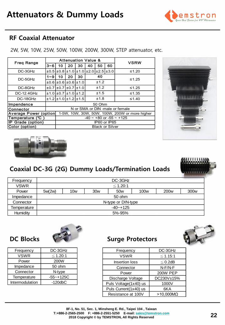
3~6 10 20 30 40 50 60
DC-3GHz ±0.5 ±0.8 ±1.0 ±1.0 ±2.0 ±2.5 ±3.0 ≤1.20
1~9 10 20 30
±0.6 ±0.6 ±0.6 ±1.0
DC-8GHz ±0.7 ±0.7 ±0.7 ±1.0 ≤1.25
DC-12.4GHz ±1.0 ±0.7 ±1.0 ±1.2 ≤1.35
DC-18GHz ±1.2 ±1.0 ±1.2 ±1.5 ≤1.40
Impendence
Connector
Temperature (℃ )
50 Ohm
1-5W, 10W, 30W, 50W, 100W, 200W or more higher
-40 ~ +80 or -55 ~ +125
±1.2
±1.2
±1.5
±1.8
N or SMA or DIN -male or female
Average Power (opt ion)
IP Grade (opt ion)
Color (opt ion)
IP60 or IP65
Black or Silver
At tenuat ion Value &Freq Range VSRW
40DC-5GHz ≤1.25
Attenuators & Dummy Loads
Coaxial DC-3G (2G) Dummy Loads/Termination Loads
Frequency
VSWR
Power 5w(2w) 10w 30w 50w 100w 200w 300w
Impedance
Connector
Temperature
Humidity
-40~+125
5%-95%
DC-3GHz
≦1.20:1
50 ohm
N-type or DIN-type
22
RF Coaxial Attenuator
8F-1, No. 51, Sec. 1, Minsheng E. Rd., Taipei 104 , Taiwan
T:+886-2-2565-2500 F: +886-2-2551-5250 E-mail: [email protected]
2018 Copyright © by TEMSTRON, All Rights Reserved
2W, 5W, 10W, 25W, 50W, 100W, 200W, 300W, STEP attenuator, etc.
DC Blocks Surge Protectors
Frequency DC-3GHz
VSWR ≦1.20:1
Power 200W
Impedance 50 ohm
Connector N-type
Temperature -55~+125C
Intermodulation -120dbC
Frequency DC-3GHz
VSWR ≦1.15:1
Insertion loss ≦0.2dB
Connector N-F/N-F
Power 200W PEP
Discharge Voltage DC230V±15%
Puls Voltage(1x40) us 1000V
Puls Current(1x40) us 6KA
Resistance at 100V >10,000MΩ
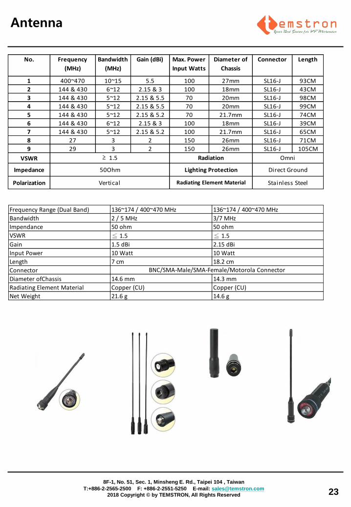
No. Frequency
(MHz)
Bandwidth
(MHz)
Gain (dBi) Max. Power
Input Watts
Diameter of
Chassis
Connector Length
1 400~470 10~15 5.5 100 27mm SL16-J 93CM
2 144 & 430 6~12 2.15 & 3 100 18mm SL16-J 43CM
3 144 & 430 5~12 2.15 & 5.5 70 20mm SL16-J 98CM
4 144 & 430 5~12 2.15 & 5.5 70 20mm SL16-J 99CM
5 144 & 430 5~12 2.15 & 5.2 70 21.7mm SL16-J 74CM
6 144 & 430 6~12 2.15 & 3 100 18mm SL16-J 39CM
7 144 & 430 5~12 2.15 & 5.2 100 21.7mm SL16-J 65CM
8 27 3 2 150 26mm SL16-J 71CM
9 29 3 2 150 26mm SL16-J 105CM
VSWR
Impedance
Polarization
50Ohm
Vertical
Omni
Direct Ground
Stainless Steel
Radiation
Lighting Protection
Radiating Element Material
≥ 1.5
Antenna
23
8F-1, No. 51, Sec. 1, Minsheng E. Rd., Taipei 104 , Taiwan
T:+886-2-2565-2500 F: +886-2-2551-5250 E-mail: [email protected]
2018 Copyright © by TEMSTRON, All Rights Reserved
Frequency Range (Dual Band) 136~174 / 400~470 MHz 136~174 / 400~470 MHz
Bandwidth 2 / 5 MHz 3/7 MHz
Impendance 50 ohm 50 ohm
VSWR ≦ 1.5 ≦ 1.5
Gain 1.5 dBi 2.15 dBi
Input Power 10 Watt 10 Watt
Length 7 cm 18.2 cm
Connector
Diameter ofChassis 14.6 mm 14.3 mm
Radiating Element Material Copper (CU) Copper (CU)
Net Weight 21.6 g 14.6 g
BNC/SMA-Male/SMA-Female/Motorola Connector
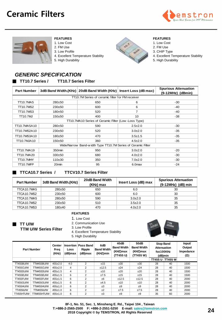
Ceramic Filters
■ TT10.7 Series / TT10.7 Series Filter
FEATURES
1. Low Cost
2. FM Use
3. Low Profile
4. Excellent Temperature Stability
5. High Durability
GENERIC SPECIFICATION
Part Number 3dB Band Width.(KHz) 20dB Band Width (KHz) Insert Loss (dB max)Spurious Attenuation
(9-12MHz) (dBmin)
TT10.7MA5 280±50 650 6 -30
TT10.7MS2 230±50 600 6 -40
TT10.7MS3 180±50 520 7 -40
TT10.7MJ 150±50 400 10 -38
TT10.7MA5A10 280±50 590 2.5±2.0 -30
TT10.7MS2A10 230±50 520 3.0±2.0 -35
TT10.7MS3A10 180±50 470 3.5±1.5 -35
TT10.7MJA10 150±50 360 4.5±2.0 -35
TT10.7MA19 350min 950 3.0±2.0 -20
TT10.7MA20 330±50 680 4.0±2.0 -30
TT10.7MHY 110±30 350 7.0±2.0 -30
TT10.7MFP 20min 95 6.0max -24
TT10.7M Series of ceramic f ilter for FM receiver
TT10.7MA10 Series of Ceramic Filter (Low -Loss Type)
Wide/Narrow Band-w idth Type TT10.7M Series of Ceramic Filter
24
■ TTCA10.7 Series / TTCV10.7 Series Filter
Part Number 3dB Band Width.(KHz)20dB Band Width
(KHz) maxInsert Loss (dB) max
Spurious Attenuation
(9-12MHz) (dB) min
TTCA10.7MA5 280±50 650 6.0 30
TTCA10.7MS2 230±50 600 6.0 30
TTCA10.7MA5 280±50 590 3.0±2.0 35
TTCA10.7MS2 230±50 510 3.5±2.0 35
TTCA10.7MS3 180±40 470 4.0±2.0 35
Center
Freq
(KHz)
Insertion
Loss
(dB)max
Pass Band
Ripple
(dB)max
6dB
Band Width
(KHZ)min
40dB
Band Width
(KHZ)max
(TT455 U)
50dB
Band Width
(KHZ)max
(TT455 W)
Input/
Output
Impedance
(Ω)
TT455 U TT455 W
TT455BU/W TTM455BU/W 455±2.0 4.0 2 ±15 ±30 ±30 28 40 1500
TT455CU/W TTM455CU/W 455±2.0 4 2 ±12.5 ±24 ±24 28 40 1500
TT455DU/W TTM455DU/W 455±1.5 4 2 ±10 ±20 ±20 28 40 1500
TT455EU/W TTM455EU/W 455±1.5 6 2 ±7.5 ±15 ±15 28 40 1500
TT455FU/W TTM455FU/W 455±1.5 6 2 ±6 ±12.5 ±12.5 28 40 2000
TT455GU/W TTM455GU/W 455±1.5 6 2 ±4.5 ±10 ±10 28 40 2000
TT455HU/W TTM455HU/W 455±1.0 6 2 ±3 ±9 ±9 28 40 2000
TT455IU/W TTM455IU/W 455±1.0 6 2 ±2 ±7.5 ±7.5 28 40 2000
TT455HTU/W TTM455HTU/W 455±1.0 6 2 ±3 ±9 ±9 35 60 2000
Part Number
Stop Band
Attenuation
fo±100KHz
(dB)min
■ TT U/W
TTM U/W Series Filter
FEATURES
1. Low Cost
2. Communication Use
3. Low Profile
4. Excellent Temperature Stability
5. High Durability
FEATURES
1. Low Cost
2. FM Use
3. CHIP Type
4. Excellent Temperature Stability
5. High Durability
8F-1, No. 51, Sec. 1, Minsheng E. Rd., Taipei 104 , Taiwan
T:+886-2-2565-2500 F: +886-2-2551-5250 E-mail: [email protected]
2018 Copyright © by TEMSTRON, All Rights Reserved
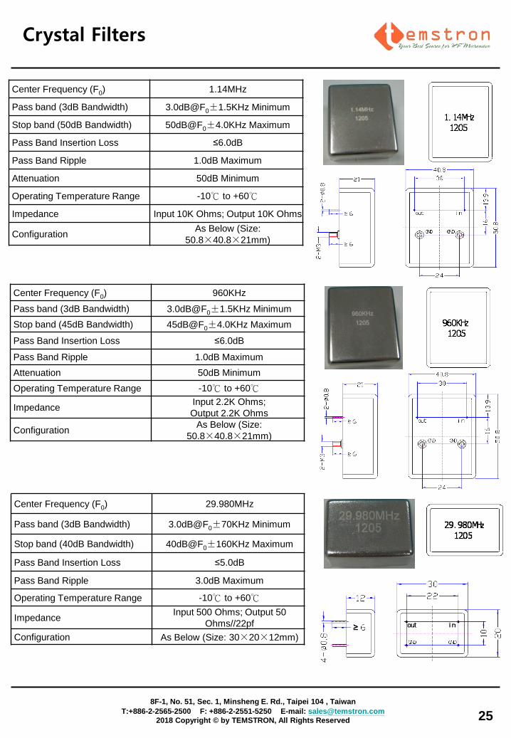
Crystal Filters
Center Frequency (F0) 1.14MHz
Pass band (3dB Bandwidth) 3.0dB@F0± 1.5KHz Minimum
Stop band (50dB Bandwidth) 50dB@F0± 4.0KHz Maximum
Pass Band Insertion Loss ≤6.0dB
Pass Band Ripple 1.0dB Maximum
Attenuation 50dB Minimum
Operating Temperature Range -10℃ to +60℃
Impedance Input 10K Ohms; Output 10K Ohms
Configuration As Below (Size:
50.8× 40.8× 21mm)
Center Frequency (F0) 960KHz
Pass band (3dB Bandwidth) 3.0dB@F0± 1.5KHz Minimum
Stop band (45dB Bandwidth) 45dB@F0± 4.0KHz Maximum
Pass Band Insertion Loss ≤6.0dB
Pass Band Ripple 1.0dB Maximum
Attenuation 50dB Minimum
Operating Temperature Range -10℃ to +60℃
Impedance Input 2.2K Ohms;
Output 2.2K Ohms
Configuration As Below (Size:
50.8× 40.8× 21mm)
Center Frequency (F0) 29.980MHz
Pass band (3dB Bandwidth) 3.0dB@F0± 70KHz Minimum
Stop band (40dB Bandwidth) 40dB@F0± 160KHz Maximum
Pass Band Insertion Loss ≤5.0dB
Pass Band Ripple 3.0dB Maximum
Operating Temperature Range -10℃ to +60℃
Impedance Input 500 Ohms; Output 50
Ohms//22pf
Configuration As Below (Size: 30× 20× 12mm)
25
8F-1, No. 51, Sec. 1, Minsheng E. Rd., Taipei 104 , Taiwan
T:+886-2-2565-2500 F: +886-2-2551-5250 E-mail: [email protected]
2018 Copyright © by TEMSTRON, All Rights Reserved
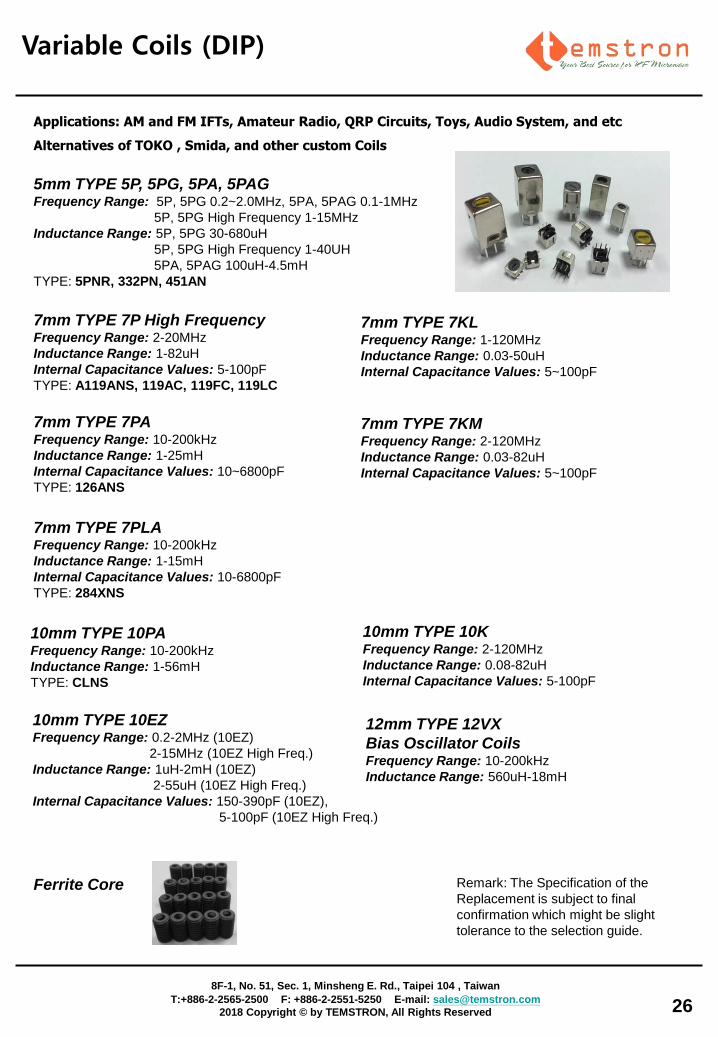
Variable Coils (DIP)
7mm TYPE 7P High Frequency Frequency Range: 2-20MHz
Inductance Range: 1-82uH
Internal Capacitance Values: 5-100pF
TYPE: A119ANS, 119AC, 119FC, 119LC
Remark: The Specification of the
Replacement is subject to final
confirmation which might be slight
tolerance to the selection guide.
26
8F-1, No. 51, Sec. 1, Minsheng E. Rd., Taipei 104 , Taiwan
T:+886-2-2565-2500 F: +886-2-2551-5250 E-mail: [email protected]
2018 Copyright © by TEMSTRON, All Rights Reserved
7mm TYPE 7PA Frequency Range: 10-200kHz
Inductance Range: 1-25mH
Internal Capacitance Values: 10~6800pF
TYPE: 126ANS
7mm TYPE 7PLA Frequency Range: 10-200kHz
Inductance Range: 1-15mH
Internal Capacitance Values: 10-6800pF
TYPE: 284XNS
10mm TYPE 10PA Frequency Range: 10-200kHz
Inductance Range: 1-56mH
TYPE: CLNS
5mm TYPE 5P, 5PG, 5PA, 5PAG Frequency Range: 5P, 5PG 0.2~2.0MHz, 5PA, 5PAG 0.1-1MHz
5P, 5PG High Frequency 1-15MHz
Inductance Range: 5P, 5PG 30-680uH
5P, 5PG High Frequency 1-40UH
5PA, 5PAG 100uH-4.5mH
TYPE: 5PNR, 332PN, 451AN
10mm TYPE 10EZ Frequency Range: 0.2-2MHz (10EZ)
2-15MHz (10EZ High Freq.)
Inductance Range: 1uH-2mH (10EZ)
2-55uH (10EZ High Freq.)
Internal Capacitance Values: 150-390pF (10EZ),
5-100pF (10EZ High Freq.)
Applications: AM and FM IFTs, Amateur Radio, QRP Circuits, Toys, Audio System, and etc
Alternatives of TOKO , Smida, and other custom Coils
Ferrite Core
10mm TYPE 10K Frequency Range: 2-120MHz
Inductance Range: 0.08-82uH
Internal Capacitance Values: 5-100pF
12mm TYPE 12VX
Bias Oscillator Coils Frequency Range: 10-200kHz
Inductance Range: 560uH-18mH
7mm TYPE 7KL Frequency Range: 1-120MHz
Inductance Range: 0.03-50uH
Internal Capacitance Values: 5~100pF
7mm TYPE 7KM Frequency Range: 2-120MHz
Inductance Range: 0.03-82uH
Internal Capacitance Values: 5~100pF
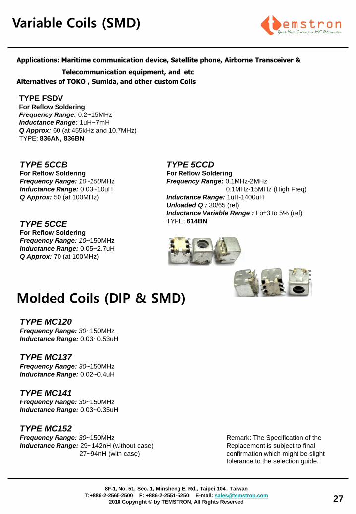
Variable Coils (SMD)
TYPE FSDV For Reflow Soldering
Frequency Range: 0.2~15MHz
Inductance Range: 1uH~7mH
Q Approx: 60 (at 455kHz and 10.7MHz)
TYPE: 836AN, 836BN
27
TYPE 5CCB For Reflow Soldering
Frequency Range: 10~150MHz
Inductance Range: 0.03~10uH
Q Approx: 50 (at 100MHz)
TYPE 5CCE For Reflow Soldering
Frequency Range: 10~150MHz
Inductance Range: 0.05~2.7uH
Q Approx: 70 (at 100MHz)
TYPE 5CCD For Reflow Soldering
Frequency Range: 0.1MHz-2MHz
0.1MHz-15MHz (High Freq)
Inductance Range: 1uH-1400uH
Unloaded Q : 30/65 (ref)
Inductance Variable Range : Lo±3 to 5% (ref)
TYPE: 614BN
Applications: Maritime communication device, Satellite phone, Airborne Transceiver &
Telecommunication equipment, and etc
Alternatives of TOKO , Sumida, and other custom Coils
Molded Coils (DIP & SMD)
TYPE MC120 Frequency Range: 30~150MHz
Inductance Range: 0.03~0.53uH
TYPE MC141 Frequency Range: 30~150MHz
Inductance Range: 0.03~0.35uH
TYPE MC152 Frequency Range: 30~150MHz
Inductance Range: 29~142nH (without case)
27~94nH (with case)
TYPE MC137 Frequency Range: 30~150MHz
Inductance Range: 0.02~0.4uH
Remark: The Specification of the
Replacement is subject to final
confirmation which might be slight
tolerance to the selection guide.
8F-1, No. 51, Sec. 1, Minsheng E. Rd., Taipei 104 , Taiwan
T:+886-2-2565-2500 F: +886-2-2551-5250 E-mail: [email protected]
2018 Copyright © by TEMSTRON, All Rights Reserved