300 and 350 series ball valve - spx flow · 300 and 350 series ball valve manual and pneumatic...
TRANSCRIPT

FPO
INSTRUCTION MANUAL
300 and 350 Series Ball ValveMANUAL AND PNEUMATIC ACTUATORS
FORM NO.: 95-03097 REVISION: 01/2017 READ AND UNDERSTAND THIS MANUAL PRIOR TO OPERATING OR SERVICING THIS PRODUCT.
Information contained in this manual is subject to change without notice and does not represent a commitment on the part of SPX FLOW, Inc. No part of this manual may be reproduced or transmitted in any form or by any means, electronic or mechanical, including photocopying and recording, for any purpose, without the express written per-mission of SPX FLOW, Inc.
Copyright © 2017 SPX FLOW, Inc.All Rights Reserved.
Revision Date: 01/2017
Publication: 95-03097
SPX FLOW, Inc.611 Sugar Creek Road
Delavan, WI 53115 USA
Tel: (800) 252-5200 or (262) 728-1900Fax: (800) 252-5012 or (262) 728-4904
E-mail: [email protected] site: www.spxflow.com

01/2017 95-03097 Page 3
Waukesha Cherry-Burrell Table of Contents
Warranty ....................................................................................................................4Shipping Damage or Loss ....................................................................................................... 4Warranty Claim ........................................................................................................................ 4
Safety ........................................................................................................................5Care of Stainless Steel ............................................................................................6
Stainless Steel Corrosion ........................................................................................................ 6Elastomer Seal Replacement Following Passivation ............................................................... 6
Introduction ..............................................................................................................7General Information ................................................................................................................. 7Factory Inspection ................................................................................................................... 7Models and Specifications ....................................................................................................... 7Equipment Serial Number ....................................................................................................... 7Operating Parameters ............................................................................................................. 7
Temperature Range .................................................................................................... 7Pressure Range .......................................................................................................... 7
Installation ................................................................................................................8Air Supply ................................................................................................................................ 8Pipeline Support ...................................................................................................................... 8Installing buttweld end ball valves ........................................................................................... 8
Maintenance .............................................................................................................9Maintenance Intervals ............................................................................................................. 9Inspection ................................................................................................................................ 9Lubrication ............................................................................................................................... 9300 Series 2-Way Ball Valve Disassembly ............................................................................ 10300 Series 2-Way Ball Valve Assembly ................................................................................. 11300 Series 2-Way Ball Valve Actuator Assembly .................................................................. 12
Mounting a Rack & Pinion actuator on the 300 Series 2-Way Manual Ball Valve .... 12Mounting a Linear actuator on the 300 Series 2-Way Manual Ball Valve ................. 13
350 Series 3-Way Ball Valve Disassembly ............................................................................ 14350 Series 3-Way Ball Valve Assembly ................................................................................. 15350 Series 3-Way Ball Valve Actuator Assembly .................................................................. 16
Mounting an actuator on the 350 Series 3-Way Manual Ball Valve .......................... 16Air/Spring Rack & Pinion actuator factory setting
orientations with no air on the valve ............................................................ 17Parts Lists ...............................................................................................................18
300 Series 2-Way Ball Valve with Manual Handle ................................................................. 18300 Series 2-Way Ball Valve with Rack and Pinion Actuator ................................................ 20300 Series 2-Way Ball Valve with Linear Actuator ................................................................ 21350 Series 3-Way Ball Valve with Manual Handle ................................................................. 22Replacement Kits - 350 Series 3-Way Ball Valve with Manual Handle ................................. 24350 Series 3-Way Ball Valve with Rack and Pinion Actuator ................................................ 25

Warranty Waukesha Cherry-Burrell Brand 300 and 350 Series Ball Valves
Page 4 95-03097 01/2017
Warranty
LIMITED WARRANTY: Unless otherwise negotiated at the time of sale, SPX FLOW US, LLC (SPX FLOW) goods, auxiliaries and parts thereof are warranted to the original purchaser against defective workmanship and material for a period of twelve (12) months from date of installation or eighteen (18) months from date of shipment from factory, whichever expires first. If the goods or services do not conform to the warranty stated above, then as Buyer's sole remedy, SPX FLOW shall, at SPX FLOW's option, either repair or replace the defective goods or re-perform defective services. Third party goods furnished by SPX FLOW will be repaired or replaced as Buyer's sole remedy, but only to the extent provided in and honored by the original manufacturer's warranty. Unless otherwise agreed to in writing, SPX FLOW shall not be liable for breach of warranty or otherwise in any manner whatsoever for: (i) normal wear and tear; (ii) corrosion, abrasion or erosion; (iii) any good or services which, following delivery or performance by SPX FLOW, has been subjected to accident, abuse, misapplication, improper repair, alteration, improper installation or maintenance, neglect, or excessive operating con-ditions; (iv) defects resulting from Buyer's specifications or designs or those of Buyer's contractors or subcontractors other than SPX FLOW; or (v) defects resulting from the manufacture, distribution, promotion or sale of Buyer's products.
THE WARRANTIES CONTAINED HEREIN ARE THE SOLE AND EXCLUSIVE WARRANTIES AVAILABLE TO BUYER AND SPX FLOW HEREBY DISCLAIMS ANY OTHER WARRANTIES, EXPRESS OR IMPLIED, INCLUDING WITHOUT LIMITATION THE IMPLIED WARRANTIES OF MERCHANTABILITY AND FITNESS FOR A PARTICULAR PURPOSE. THE FOREGOING REPAIR, REPLACEMENT AND RE-PERFORMANCE OBLIGA-TIONS STATE SPX FLOW'S ENTIRE AND EXCLUSIVE LIABIL-ITY AND BUYER'S EXCLUSIVE REMEDY FOR ANY CLAIM IN CONNECTION WITH THE SALE AND FURNISHING OF SER-VICES, GOODS OR PARTS, THEIR DESIGN, SUITABILITY FOR USE, INSTALLATION OR OPERATIONS.
Shipping Damage or Loss If equipment is damaged or lost in transit, file a claim at once with the delivering carrier. The carrier has a signed Bill of Lading acknowledging that the shipment has been received from SPX FLOW in good condition. SPX FLOW is not responsible for the collection of claims or replacement of materials due to transit shortage or damages.
Warranty Claim Warranty claims must have a Returned Material Authorization (RMA) from the Seller or returns will not be accepted. Contact 800-252-5200 or 262-728-1900.
Claims for shortages or other errors must be made in writing to Seller within ten (10) days after delivery. This does not include transit shortage or damages. Failure to give such notice shall constitute acceptance and waiver of all such claims by Buyer.

Waukesha Cherry-Burrell Brand 300 and 350 Series Ball Valves Safety
01/2017 95-03097 Page 5
SafetyREAD AND UNDERSTAND THIS MANUAL PRIOR TO INSTALLING, OPERATING OR SERVICING THIS EQUIPMENT
SPX FLOW recommends users of our equipment and designs follow the latest Industrial Safety Standards. At a minimum, these should include the industrial safety requirements established by:
1. Occupational Safety and Health Administration (OSHA), Title 29 of the CFR Section 1910.212- General Requirements for all Machines
2. National Fire Protection Association, ANSI/NFPA 79 ANSI/NFPA 79- Electrical Standards for Industrial Machinery
3. National Electrical Code, ANSI/NFPA 70 ANSI/NFPA 70- National Electrical Code ANSI/NFPA 70E- Electrical Safety Requirement for Employee Workplaces
4. American National Standards Institute, Section B11
Attention: Servicing energized industrial equipment can be hazardous. Severe injury or death can result from electrical shock, burn, or unintended actuation of controlled equipment. Recommended practice is to discon-nect and lockout industrial equipment from power sources, and release stored energy, if present. Refer to the National Fire Protection Association Standard No. NFPA70E, Part II and (as applicable) OSHA rules for Con-trol of Hazardous Energy Sources (Lockout-Tagout) and OSHA Electrical Safety Related Work Practices, including procedural requirements for:
• Lockout-tagout
• Personnel qualifications and training requirements
• When it is not feasible to de-energize and lockout-tagout electrical circuits and equipment before working on or near exposed circuit parts
Locking and Interlocking Devices: These devices should be checked for proper working condition and capa-bility of performing their intended functions. Make replacements only with the original manufacturer’s renewal parts or kits. Adjust or repair in accordance with the manufacturer’s instructions.
Periodic Inspection: Industrial equipment should be inspected periodically. Inspection intervals should be based on environmental and operating conditions and adjusted as indicated by experience. At a minimum, an initial inspection within 3 to 4 months after installation is recommended. Inspection of the electrical control sys-tems should meet the recommendations as specified in the National Electrical Manufacturers Association (NEMA) Standard No. ICS 1.3, Preventative Maintenance of Industrial Control and Systems Equipment, for the general guidelines for setting-up a periodic maintenance program.
Replacement Equipment: Use only replacement parts and devices recommended by the manufacturer to maintain the integrity of the equipment. Make sure the parts are properly matched to the equipment series, model, serial number, and revision level of the equipment.
Warnings and cautions are provided in this manual to help avoid serious injury and/or possible damage to equipment:
DANGER: marked with a stop sign. Immediate hazards which WILL result in severe personal injury or death.
WARNING: marked with a warning triangle. Hazards or unsafe practices which COULD result in severe personal injury or death.
CAUTION: marked with a warning triangle. Hazards or unsafe practices which COULD result in minor personal injury or product or property damage.

Care of Stainless Steel Waukesha Cherry-Burrell Brand 300 and 350 Series Ball Valves
Page 6 95-03097 01/2017
Care of Stainless Steel
Stainless Steel Corrosion
Corrosion resistance is greatest when a layer of oxide film is formed on the surface of stainless steel. If film is disturbed or destroyed, stainless steel becomes much less resistant to corrosion and may rust, pit or crack.
Corrosion pitting, rusting and stress cracks may occur due to chemical attack. Use only cleaning chemicals specified by a reputable chemical manufacturer for use with 300 series stainless steel. Do not use exces-sive concentrations, temperatures or exposure times. Avoid contact with highly corrosive acids such as hydrofluoric, hydrochloric or sulfuric. Also avoid prolonged contact with chloride-containing chemicals, especially in presence of acid. If chlorine-based sanitizers are used, such as sodium hypochlorite (bleach), do not exceed concentrations of 150 ppm available chlorine, do not exceed contact time of 20 minutes, and do not exceed temperatures of 104°F (40°C).
Corrosion discoloration, deposits or pitting may occur under product deposits or under gaskets. Keep surfaces clean, including those under gaskets or in grooves or tight corners. Clean immediately after use. Do not allow equipment to set idle, exposed to air with accumulated foreign material on the surface.
Corrosion pitting may occur when stray electrical currents come in contact with moist stainless steel. Ensure all electrical devices connected to the equipment are correctly grounded.
Elastomer Seal Replacement Following Passivation
Passivation chemicals can damage product contact areas of this equip-ment. Elastomers (rubber components) are most likely to be affected. Always inspect all elastomer seals after passivation is completed. Replace any seals showing signs of chemical attack. Indications may include swelling, cracks, loss of elasticity or any other noticeable changes when compared with new components.

Waukesha Cherry-Burrell Brand 300 and 350 Series Ball Valves Introduction
01/2017 95-03097 Page 7
Introduction
General Information Information in this manual should be read by all personnel involved in installation, setup, operation and maintenance.
Always use installation tools and lubricants recommended by SPX FLOW. SPX FLOW products are subject to intensive inter-mediate and final leakage and functional tests.
Factory Inspection Each Waukesha Cherry-Burrell brand valve is shipped com-pletely assembled, lubricated and ready for use.
Models and Specifications The Waukesha Cherry-Burrell brand 300 Series 2-Way Ball Valve is available with a manual handle, rack and pinion actuator, or lin-ear actuator.
The Waukesha Cherry-Burrell brand 350 Series 3-Way Ball Valve is available with a manual handle or rack and pinion actuator.
Materials
• Ball and Body: 3166L Stainless Steel
• Seat: PTFE
Equipment Serial Number For Waukesha Cherry-Burrell brand valves with actuators, the valves are identified by a serial number found on the label on the actuator cylinder. Valves with a manual handle are not labeled with a serial number.
Operating Parameters Temperature Range
• 300 Series 2-Way Ball Valve: 0° to 300°F (-17° to 148°C)
• 350 Series 3-Way Ball Valve: 0° to 350°F (-17° to 175°C)
Solenoid valves may not be used in the control module in room environments below 32°F (0°C) and over 140°F (60°C), as func-tion cannot be guaranteed.
Pressure Range
Valve Type Valve Size Operating Pressure:
300 Series 2-Way
1/2” - 3/4" up to 1300 psi (90 bar)
1” – 1 1/2" up to 1100 psi (76 bar)
2’’ – 4’’ up to 900 psi (62 bar)
350 Series 3-Way
1/2” - 2” up to 1000 psi (69 bar)
2 1/2” - 4” up to 800 psi (55 bar)
Installation Waukesha Cherry-Burrell Brand 300 and 350 Series Ball Valves
Page 8 95-03097 01/2017
Installation
Air Supply Install the valves using dry, filtered air. Lubrication is not required. If using lubricated air, refer to the solenoid manufacturer’s specifi-cations.
The air supply requirements are as follows:
• Linear Actuator: 87 psi (6 bar) minimum; 145 psi (10 bar) maximum.
• Rack & Pinion Actuator: 40 psi (3 bar) minimum; 120 psi (8 bar) maximum.
Pipeline Support
Figure 1 - Pipeline Support
C G
D
E
F
VA100-048
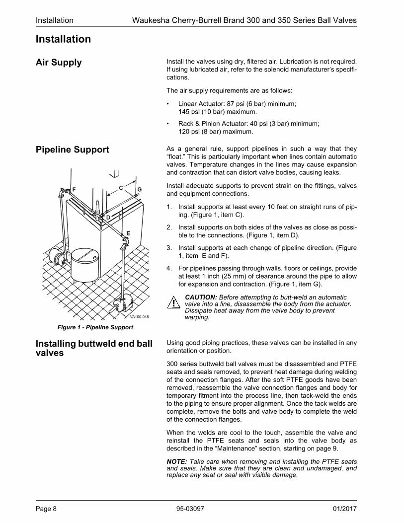
As a general rule, support pipelines in such a way that they “float.” This is particularly important when lines contain automatic valves. Temperature changes in the lines may cause expansion and contraction that can distort valve bodies, causing leaks.
Install adequate supports to prevent strain on the fittings, valves and equipment connections.
1. Install supports at least every 10 feet on straight runs of pip-ing. (Figure 1, item C).
2. Install supports on both sides of the valves as close as possi-ble to the connections. (Figure 1, item D).
3. Install supports at each change of pipeline direction. (Figure 1, item E and F).
4. For pipelines passing through walls, floors or ceilings, provide at least 1 inch (25 mm) of clearance around the pipe to allow for expansion and contraction. (Figure 1, item G).
CAUTION: Before attempting to butt-weld an automatic valve into a line, disassemble the body from the actuator. Dissipate heat away from the valve body to prevent warping.
Installing buttweld end ball valves
Using good piping practices, these valves can be installed in any orientation or position.
300 series buttweld ball valves must be disassembled and PTFE seats and seals removed, to prevent heat damage during welding of the connection flanges. After the soft PTFE goods have been removed, reassemble the valve connection flanges and body for temporary fitment into the process line, then tack-weld the ends to the piping to ensure proper alignment. Once the tack welds are complete, remove the bolts and valve body to complete the weld of the connection flanges.
When the welds are cool to the touch, assemble the valve and reinstall the PTFE seats and seals into the valve body as described in the “Maintenance” section, starting on page 9.
NOTE: Take care when removing and installing the PTFE seats and seals. Make sure that they are clean and undamaged, and replace any seat or seal with visible damage.

Waukesha Cherry-Burrell Brand 300 and 350 Series Ball Valves Maintenance
Maintenance
Maintenance Intervals Maintain adequate stock of replacement parts. See the items listed under "Replacement Kits" on page 19 for 300 Series 2-Way Ball Valves, and page 23 for 350 Series 3-Way Ball Valves.
Maintenance intervals should be determined by the user and spe-cific application, based on the following conditions:
• Daily operation period
• Switching frequency
• Application parameters, such as temperature, pressure, and flow
• Product type
Inspection Inspect the following on a regular basis:
• Valve body gaskets and ball seats
• Pneumatic connections:
• Air pressure at supply connection
• Air lines for kinks and leaks
• Threaded connections for tight fit
• Clean air filter at regular intervals
• Electrical connections secure on control module:
• Wire connections tight on terminal strip
• Electrical connections to control module
• Threaded strain relief for tight fit.
Lubrication No lubrication is required other as than noted in the disassembly and assembly procedures. (Use food grade non-petroleum (sili-cone) grease on seals and o-rings.)
Apply Bostik Never-Seez® White Food Grade with PTFE or equivalent to all bolts and threaded stem parts.
01/2017 95-03097 Page 9

Maintenance Waukesha Cherry-Burrell Brand 300 and 350 Series Ball Valves
300 Series 2-Way Ball Valve Disassembly
Figure 2 - 300-Series 2-Way Ball Valve
14
2
2
10
3
9
13 8
15
11
7
3 VA100-745a
54
6
16
1
1
17
1. Remove the nut and washer (Figure 2, items 9 and 10) and slide off the manual handle (item 11).
2. Place the handle (item 11) back on the stem (item 13) and turn the handle to close the valve.
3. Remove the handle (item 11) and gland hex nut (item 8), then tip the valve upside down to retrieve the stem packing (item 15).
4. Remove the bolt nuts and washers (items 16 and 17). Pull off the flange tail pieces (item 1).
5. Rotate and push the ball (item 5) toward the ball seats (item 3), creating some movement on the seats. Once one of the ball seats (item 3) moves out of the valve body (item 4), press the ball seat out of the valve body with your fingers.
6. The ball (item 5) should now fall out of the body. Push the remaining ball seat (item 3) out of the valve from the open end.
7. Push the stem (item 13) down from the top into the valve, and remove it with the thrust washer (item 14).
8. The valve is now fully disassembled.
Table 1: Callouts for Figure 2
1. Tail Piece2. Gasket3. Ball Seat4. Body5. Ball Seat6. Bolt7. Stopper Pin8. Gland9. Washer10. Nut11. Handle13. Stem14. Thrust Washer15. Stem Packing16. Bolt Nut17. Bolt Washer
Page 10 95-03097 01/2017

Waukesha Cherry-Burrell Brand 300 and 350 Series Ball Valves Maintenance
300 Series 2-Way Ball Valve Assembly
1. See Figure 2 on page 10. Slide the thrust washer (item 14) over the stem (item 13). Holding the stem threads up, guide the stem from inside the body (item 4) up through the center hole. Turn the stem to align the key along the flow direction.
2. Drop the stem packing washers (item 15), then the gland hex nut (item 8) onto the stem from the top. Hand-tighten the gland hex nut (item 8) while making sure the stem key remains in position.
3. Slide the ball (item 5) into the valve, making sure the slot on the ball centers on the stem key. Press one ball seat (item 3) into the body. Place the Teflon™ gasket (item 2) on the body (item 4).
4. Align the first valve flange tail piece (item 1) with the bolt holes of the valve body, on the same side that the ball seat (item 3) was inserted in step 3.
5. Flip the sub assembly over, placing the clamp face of the first flange tail piece (item 1) down on a flat surface. Slide the opposite side ball seat (item 3) into the valve body. Place the Teflon™ gasket (item 2) on the body (item 4).
6. Align the opposite valve flange tail piece (item 1) with the bolt holes of the valve body (item 4). Slide the bolts (item 6) through the top valve flange to the bottom flange. Hand-tighten the washers and nuts (items 17 and 16) onto the bolts (item 6).
7. Tighten down the gland hex nut (item 8) and bolts (item 6). See Table 2.
8. Drop the handle (item 11) down onto the stem. Thread in the stopper pin (item 7) onto the mounting pad of valve. Drop the washer (item 9) on the stem over the handle, then thread the hex nut (item 10) onto the stem (item 13).
9. Turn the handle and inspect the ball to ensure the proper open and close positions. The handle should hit the stopper pin (item 7) in fully open and fully closed positions.
NOTE: To install the appropriate actuator for this valve, see pages 12 and 13.
Table 2: Torque Values for 300 Series Ball Valve Assembly
SizeStem Glandin-lb (n-m)
Body Boltsin-lb (n-m)
1/2" 80 (9.04) 100 (11.30)
3/4" 80 (9.04) 110 (12.43)
1" 100 (11.30) 120 (13.56)
1 1/2" 250 (28.25) 270 (30.51)
2" 250 (28.25) 280 (31.64)
2 1/2" 300 (33.90) 390 (44.06)
3" 500 (56.49) 560 (63.27)
4" 700 (79.09) 750 (84.74)
01/2017 95-03097 Page 11

Maintenance Waukesha Cherry-Burrell Brand 300 and 350 Series Ball Valves
300 Series 2-Way Ball Valve Actuator Assembly
Figure 3 - Mount Rack & Pinion Actuator
2
1
13
7
5
VA100-756
Mounting a Rack & Pinion actuator on the 300 Series 2-Way Manual Ball Valve
1. Per the instructions in step 1 on page 10, remove the handle nut and handle from the ball valve.
2. See Figure 3. Determine the actuator and valve shaft orienta-tion, then slide the coupling adapter (item 1) onto the valve shaft (item 13).
3. Attach the mounting bracket (item 2) to the mounting pad (item 7) of the valve with hex bolts and flat and lock washers.
4. Insert the square end of the coupling adapter (item 1) into the actuator (item 5), then bolt the actuator on the mounting bracket (item 2) with hex bolts and flat and lock washers. See page 20 for parts lists, including bolts and washers.
NOTE: A double square actuator insert may be required between the coupling adapter and the actuator. See parts list on page 20.
Page 12 95-03097 01/2017

Waukesha Cherry-Burrell Brand 300 and 350 Series Ball Valves Maintenance
Mounting a Linear actuator on the 300 Series 2-Way Manual Ball Valve
1. Per the instructions in step 1 on page 10, remove the handle nut and handle from the ball valve.
2. See Figure 4. Determine the actuator and valve shaft orienta-tion, then slide the coupling adapter (item 1) onto the valve shaft (item 13).
3. Attach the mounting bracket (item 2) to the mounting pad (item 7) of the valve with hex bolts and flat and lock washers.
4. Insert the actuator stem (item 8) into the coupling adapter (item 1), then bolt the actuator on the mounting bracket (item 2) with hex bolts. See page 21 for parts lists, including bolts and washers.
Figure 4 - Mount Linear Actuator
2
1
VA100-754
13
7
8
5
01/2017 95-03097 Page 13

Maintenance Waukesha Cherry-Burrell Brand 300 and 350 Series Ball Valves
350 Series 3-Way Ball Valve Disassembly
Figure 5 - 350-Series 3-Way Ball Valve
1
2
3
4
3
5
6
7
8
9
10
12
11
19
16
1813
20
21
14
15
17
VA100-750a
Table 3: Callouts for Figure 5
1. Handle2. Handle Nut3. Bevel Washer4. Lock Nut5. Stainless Ring6. Female Bevel Washer7. Double Bevel Washer8. Bevel Washer9. Teflon™ Ring10. Stem O-Ring11. Stem 12. Stop Pin13. Ball Seat #214. Ball15. Gasket16. No Flow Cap17. Ferrule Cap18. Seat Cap19. Ball Seat #120. Bolt with Lock Washer21. Valve Body
1. Remove the handle nut (item 2) and slide off the manual han-dle (item 1).
2. Using a socket wrench, remove the lock nut (item 4), then tip the valve upside down to retrieve the bevel washer (item 3) and stainless ring (item 5).
3. Remove bolts and washers (items 20) from all 4 sides. Remove the no flow cap (item 16) and ferrule caps (item 17).
4. Rotate and push the ball (item 14) towards the ball seats (items 13 and 19), creating some movement on the seats.
5. Once one of the ball seats moves out of the valve body (item 21), press the ball seat out of the valve body with your fin-gers. Continue this for all four ball seats.
NOTE: Note: Ball seat #1 (item 19) does not have to be completely removed to extract the ball.
6. Once the two ball seats (item 13) have been removed and opposite ball seats (item 19) have been slid out of the way, remove the ball from the body.
7. From the top, push the stem (item 11) down into the body of the valve. The stem o-ring and Teflon™ ring (items 9 and 10) will remain on the stem.
8. The valve is now fully disassembled.
NOTE: For part numbers and a larger image of Figure 5, see page 22.
Page 14 95-03097 01/2017

Waukesha Cherry-Burrell Brand 300 and 350 Series Ball Valves Maintenance
350 Series 3-Way Ball Valve Assembly
Please refer to Figure 5 on page 14.
1. With the Teflon™ ring and stem O-ring (items 9 and 10) installed on the stem (item 11), insert the stem through the inside of the body through the gland port, facing the exposed threads away from the product contact area. Orient the stem inside the body so that the pin and ball default to the pre-ferred direction of flow when assembly is complete.
2. Over the threaded portion of the stem, install the bevel washer (item 8), followed by the double bevel washer, and the female bevel washer (items 7 and 6), so that they fit down into the gland.
3. Next install the stainless ring (item 5) followed by (qty. 2) bevel washers (item 3), followed with the lock nut (item 4). Finger-tighten the lock nut.
4. Position the ball (item 14) in the valve body so the groove on the top of the ball and the stem (item 11) have a loose fit.
5. With the ball in the valve body, insert (qty. 2) of ball seat # 1 (item 19) until it is flush with the housing (item 21) and holds the ball (item 14) in position.
6. Next install (qty. 2) ball seat # 2 and (qty. 2) gaskets (items 13 and 15), so that the large gussets of ball seats # 2 slide into the body and mate with ball seat # 1 (item 19). The smaller gusset should be oriented on top to provide clear-ance for the stem (item 11).
7. Prior to installation of the back plate (item 16), install the seat cap (item 18) into the ball seat # 2 (item 13), located where the back plate (item 16) will be installed.
8. Starting with the back plate (item 16), install the bolts and lock washers finger-tight, followed by the other 3 connection covers (item 17).
9. Tighten down the gland lock nut (item 4) to the specified torque value (see Table 4). Then tighten the body bolts on all connection covers (item 15) and back plate (item 16).
10. Install the bevel washer (item 3), handle (item 1), and handle nut (item 2), and tighten.
NOTE: (To install the appropriate actuator for this valve, see “Mounting an actuator on the 350 Series 3-Way Manual Ball Valve” on page 16.)
Table 4: Torque Values for 350 Series Ball Valve Assembly
SizeStem Glandin-lb (n-m)
Body Boltsin-lb (n-m)
1/2" 40 (4.52) 80 (9.04)
3/4" 40 (4.52) 80 (9.04)
1" 50 (5.65) 100 (11.30)
1 1/2" 125 (14.12) 280 (31.64)
2" 125 (14.12) 400 (45.19)
2 1/2" 200 (22.60) 400 (45.19)
3" 200 (22.60) 580 (65.53)
4" 250 (28.25) 800 (90.39)
01/2017 95-03097 Page 15

Maintenance Waukesha Cherry-Burrell Brand 300 and 350 Series Ball Valves
350 Series 3-Way Ball Valve Actuator Assembly
Figure 6 - Remove Handle
2
1
VA100-753a
Mounting an actuator on the 350 Series 3-Way Manual Ball Valve
1. See Figure 6. Remove the handle nut (item 2), then remove the handle (item 1) from the ball valve.
2. Determine the actuator and valve shaft orientation.
3. See Figure 7. Place the actuator on the mounting pad (item 7), then bolt on the actuator with hex bolts and flat and lock washers. See page 25 for parts lists, including bolts and washers.
NOTE: A double square actuator insert may be required between the coupling adapter and the actuator. See parts list on page 25.
Figure 7 - Bolt on Actuator
VA100-753b
7
Page 16 95-03097 01/2017

Waukesha Cherry-Burrell Brand 300 and 350 Series Ball Valves Maintenance
Air/Spring Rack & Pinion actuator factory setting orientations with no air on the valve
L-Port Valves
Normally Open (NO)
VA100-758
Normally Closed (NC)
VA100-757
T-Port Valves
Normally Open (NO)
VA100-759
Normally Closed (NC)
VA100-757
01/2017 95-03097 Page 17

Parts Lists Waukesha Cherry-Burrell Brand 300 and 350 Series Ball Valves
Parts Lists
300 Series 2-Way Ball Valve with Manual Handle
* included in Repair Kit
Components not identified in the illustration above are not available individually. See "Complete (Assembled) Valve with Handle" part numbers, below.
Valve size Part Number
1/2" 2500000EKIT3/4" 2500000FKIT1" 25000001KIT
1 1/2" 25000002KIT2" 25000003KIT
2 1/2" 25000004KIT3" 25000005KIT4" 25000006KIT
PL5027-CH172
Repair Kits
Kit includes items 2, 3, 14, and 15(marked with *)
Valve size S-Line Buttweld
1/2" WBV30000001 WBV30000002
3/4" WBV30000003 WBV30000004
1" WBV30000005 WBV30000006
1 1/2" WBV30000007 WBV30000008
2" WBV30000009 WBV30000010
2 1/2" WBV30000011 WBV30000012
3" WBV30000013 WBV300000144" WBV30000015 WBV30000016
PL5027-CH173
Complete (Assembled) Valve with Handle
14*
2*
2*
10
3*
9
13 8
15*
11
7
3* VA100-745
Page 18 95-03097 01/2017

Waukesha Cherry-Burrell Brand 300 and 350 Series Ball Valves Parts Lists
1/2" 3/4" 1" 1 1/2"
* 2 2 Gasket
* 3 2 Ball Seat 7 1 Stopper Pin 07RP2395050 8 1 Gland 07RP2384025 250PN081520 9 1 Washer 07RP2396050 10 1 Nut 07RP2397050 11 1 Handle 250000100H 250000300H 13 1 Stem 07RP2366015 07RP2366020 07RP2366025 250L073STEM
* 14 1 Thrust Washer
* 15 2 Stem Packing
2" 3 1/2" 3" 4"
* 2 2 Gasket * 3 2 Ball Seat
7 1 Stopper Pin 07RP2395050 07RP2395100 8 1 Gland 250PN081520 250GLAND604 9 1 Washer 07RP2396050 07RP2396100 10 1 Nut 07RP2397050 07RP2397100 11 1 Handle 250000300H 250000600H 13 1 Stem 250L073STEM 250L076STEM
* 14 1 Thrust Washer * 15 2 Stem Packing
PL5027-CH170* included in Repair Kit
Components not identified in the illustration are not available individually.
Item # Qty. Part Description Note
Item # Qty. Part DescriptionValve Size
Note
250000F00H
07RP2395025
See Repair KitSee Repair Kit
See Repair KitSee Repair Kit
See Repair KitSee Repair Kit
Valve Size
07RP2384020 07RP2396025 07RP2397025
See Repair KitSee Repair Kit
07RP2395080 07RP2384080 07RP2396080 07RP2397080 250000500H
250L075STEM
Part Description Part NumberValve Handle, 1/2" & 3/4" 132964+Valve Handle, 1" 132965+Valve Handle, 1-1/2" & 2" 132966+Valve Handle 2-1/2" & 3" 132967+Valve Handle 4" 132968+
PL5027-CH171
Manual Handle Kit
Kit includes items 7, 9, 10, & 11.
300 Series 2-Way Ball Valve with Manual Handle
01/2017 95-03097 Page 19

Parts Lists Waukesha Cherry-Burrell Brand 300 and 350 Series Ball Valves
300 Series 2-Way Ball Valve with Rack and Pinion Actuator
NOTE: For item 6, see page 18.
5
3, 3a, 3b
4, 4a,4b
2
1
6
VA100-748
Item # Part Description 1/2" 3/4" 1" 1 1/2" 2" 2 1/2" 3" 4"1 Coupling Adapter 130541+ 130544+2 Mounting Bracket 130537+
3Valve Side Bolts (4 pieces)
3/8''-16 x 1.0''(P/N 30-30)
3aValve Side Flat Washers (4 pieces)
3/8''(P/N 43-30)
3bValve Side Lock Washers (4 pieces)
3/8''(P/N 43-28)
4Actuator Side Bolts (4 pieces)
M8-1.0 x 16mm(P/N 30-633)
4aActuator Side Flat Washers (4 pieces)
5/16'' (P/N 43-14)
4bActuator Side Lock Washers (4 pieces)
5/16'' (P/N 43-15)
Actuator (Air/Air) 130552+ 130555+
Actuator (Air/Spring)130546+
(Insert 14M11)130548+
(Insert 22M17)130549+
(Insert 27M17)130550+
(Insert 27M22)
6 Manual Valve
PL5027-CH175
130540+ 130542+130536+ 130538+
130543+130539+
130554+
5
130551+
3/8'' (P/N 43-30)
M5-0.8 x 12mm (P/N 130813+)
5/16''-18 x .75''(P/N 30-151)
10-24 x .50" (P/N 130811+)
1/4''-20 x .625''(P/N 30-181)
3/8'' (P/N 43-28)
5/16'' (P/N 43-14)
M6-1.0 x 12mm (P/N 130814+)
1/4'' (P/N 43-27)
M10-1.5 x 20mm (130815+)
#10 (P/N 43-21)
#10 WIDE (P/N 130812+)
1/4''(P/N 43-27)
See note below
130553+
130545+ (Insert 11M9)
130547+ (Insert 17M14)
1/4''(P/N 43-22)
#10 WIDE (P/N 130812+)
5/16''(P/N 43-15)
#10 (P/N 43-21)
1/4'' (P/N 43-22)
Page 20 95-03097 01/2017

Waukesha Cherry-Burrell Brand 300 and 350 Series Ball Valves Parts Lists
300 Series 2-Way Ball Valve with Linear Actuator
NOTE: For item 6, see page 18.
VA100-749
5
3, 3a, 3b
4
2
16
Item # Part Description 1/2" 3/4" 1" 1 1/2" 2" 2 1/2" 3" 4"1 Coupling Adapter 130499+ 130503+2 Mounting Bracket 130495+
3Valve Side Bolts (4 pieces)
3/8''-16 x 1.0''(P/N 30-30)
3aValve Side Flat Washers (4 pieces)
3/8'' (P/N 43-30)
3bValve Side Lock Washers (4 pieces)
3/8'' (P/N 43-28)
4Actuator Side Bolts (2 pieces)Actuator (Air/Air) for control unitActuator (Air/Spring) for control unitActuator (Air/Air)Actuator (Air/Spring)
6 Manual Valve
PL5027-CH174
1/4'' (P/N 43-27)
5/16''-18 x .50''(P/N 30-163)
5/16'' (P/N 43-14)
130501+
#10 (P/N 43-21) 1/4'' (P/N 43-22) 5/16'' (P/N 43-15)
H328358
H328353
H328361H328355
See note below
130497+
H328360H203917
10-24 x .50" (P/N 130811+)
M10 x 14mm (P/N 130810+)
5
H328357
130498+130494+
130500+130496+
H203918
#10 WIDE (P/N 130812+)
M8 x 12mm (P/N 130809+)
1/4''-20 x .625''(P/N 30-181)
01/2017 95-03097 Page 21

Parts Lists Waukesha Cherry-Burrell Brand 300 and 350 Series Ball Valves
350 Series 3-Way Ball Valve with Manual Handle
1
2
3
4
3
5
6
7
8
9
10
12
11
19
16
1813
15
VA100-750aVA100-750ab
Complete (Assembled) Valve with Handle
Size Style S-LineL-Port WBV35000001T-Port WBV35000002L-Port WBV35000003T-Port WBV35000004L-Port WBV35000005T-Port WBV35000006L-Port WBV35000007T-Port WBV35000008L-Port WBV35000009T-Port WBV35000010L-Port WBV35000011T-Port WBV35000012L-Port WBV35000013T-Port WBV35000014L-Port WBV35000015T-Port WBV35000016
PL5027-CH180
2 1/2"
3"
4"
1/2"
3/4"
1"
1 1/2"
2"
VA100-751
T-Port L-Port
Part Description Part NumberValve Handle, 1/2" & 3/4" 132969+Valve Handle, 1" 132970+Valve Handle, 1-1/2" & 2" 132971+Valve Handle, 2-1/2" 132972+Valve Handle, 3" & 4" 132973+
PL5027-CH182
Manual Handle Kit
Kit includes items 1, 2, 3 & 12.
Page 22 95-03097 01/2017

Waukesha Cherry-Burrell Brand 300 and 350 Series Ball Valves Parts Lists
350 Series 3-Way Ball Valve with Manual Handle
* Included in Replacement Kit1. Items 9, 10, and 11 are inside the valve body when assembled.2. Components not identified in the illustration are not available individually. See "Complete (Assembled) Valve with Han-
dle" part numbers list on page 22.3. For replacement kits, see page 24.
1/2" 3/4" 1" 1 1/2"
1 1 Handle 131675+ 131675+ 131676+ 131677+
2 1 Handle Nut 07RP24114025 07RP24114050
3 3 Bevel Washer 07RP24124025 07RP241240504 1 Lock Nut 07RP24134025 07RP241340505 1 Stainless Ring 07RP24144025 07RP24144050
* 6 1 Female Bevel Washer
* 7 1 Double Bevel Washer
* 8 1 Bevel Washer
* 9 1 Teflon™ Ring 1
* 10 1 Stem O-Ring 1L-Style Stem 07RP24096015 07RP24096020 07RP24096025 07RP24096050 1T-Style Stem 07RP24096515 07RP24096520 07RP24096525 07RP24096550
12 1 Stop Pin 07RP24154050
* 13 2 Ball Seat # 2
* 15 2 Gasket
* 18 1 Seat Cap* 19 2 Ball Seat # 1
2" 3 1/2" 3" 4"
1 1 Handle 131677+ 130618+ 130619+ 130619+ 2 1 Handle Nut 07RP24114050 07RP24114065 3 3 Bevel Washer 07RP24124050 07RP24124065
4 1 Lock Nut 07RP24134050 07RP241340655 1 Stainless Ring 07RP24144050 07RP24144065
* 6 1 Female Bevel Washer* 7 1 Double Bevel Washer* 8 1 Bevel Washer* 9 1 Teflon™ Ring 1* 10 1 Stem O-Ring 1
L-Style Stem 07RP24096050 07RP24096065 1T-Style Stem 07RP24096550 07RP24096565
12 1 Stop Pin 07RP24154050 07RP24154065* 13 2 Ball Seat # 2* 15 2 Gasket* 18 1 Seat Cap* 19 2 Ball Seat # 1
PL5027-CH178
11 1
See Replacement KitSee Replacement KitSee Replacement KitSee Replacement KitSee Replacement Kit
See Replacement Kit
See Replacement KitSee Replacement KitSee Replacement KitSee Replacement Kit
11 1
07RP2411402007RP2412402007RP2413402007RP24144020
07RP24154025
07RP24114100
See Replacement KitSee Replacement KitSee Replacement Kit
See Replacement Kit
Part DescriptionValve Size
07RP2413410007RP24144100
Note
See Replacement Kit
See Replacement Kit
07RP24124100
See Replacement KitSee Replacement Kit
Note
07RP2409610007RP2409660007RP24154100
Item # Qty. Part DescriptionValve Size
Item # Qty.
01/2017 95-03097 Page 23
Parts Lists Waukesha Cherry-Burrell Brand 300 and 350 Series Ball Valves
Old Style (pre-May 2015)
New Style (starting May 2015)
1/2" 350000EKIT 350000EKIT-13/4" 350000FKIT 350000FKIT-11" 3500001KIT 3500001KIT-1
1 1/2" 3500002KIT 3500002KIT-12" 3500003KIT 3500003KIT-1
2 1/2" 3500004KIT 3500004KIT-13" 3500005KIT 3500005KIT-14" 3500006KIT 3500006KIT-1
PL5027-CH179
Replacement KitsPart Number
Valve size
Replacement Kits - 350 Series 3-Way Ball Valve with Manual Handle
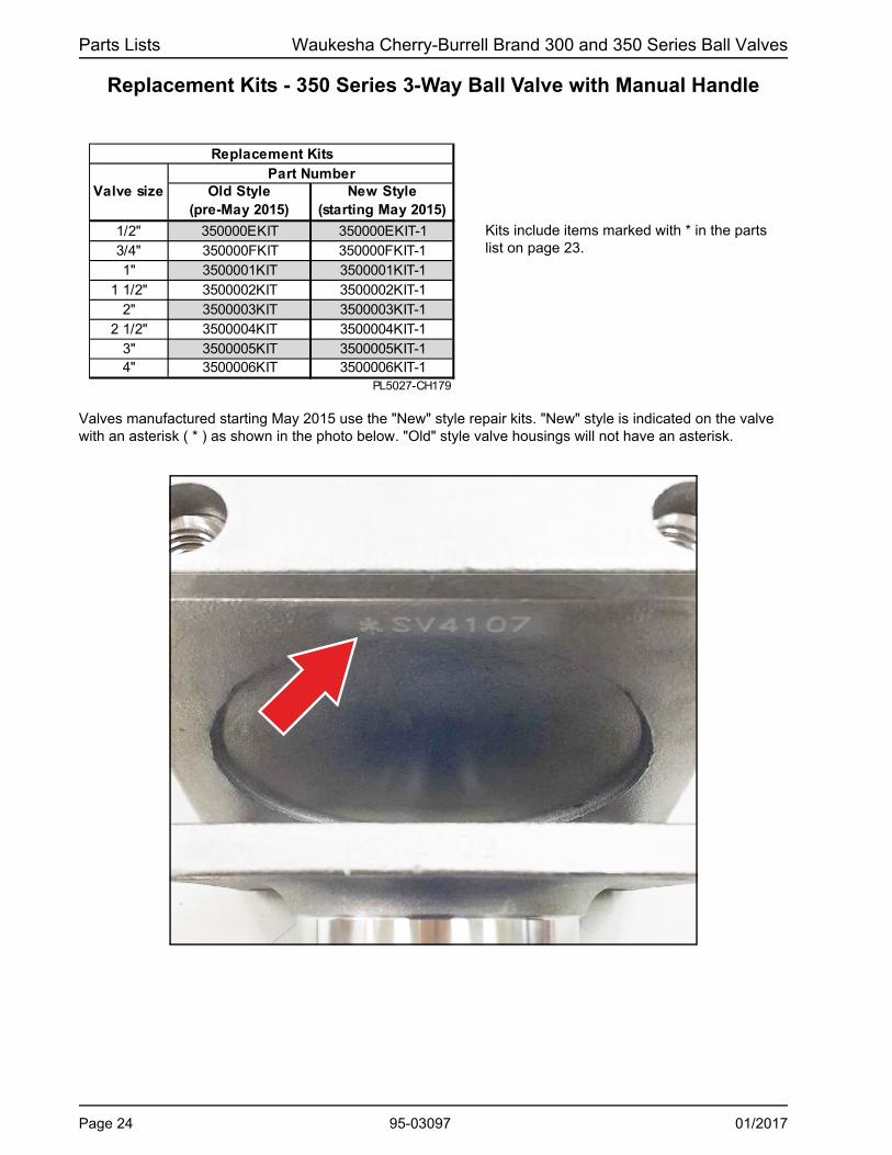
Valves manufactured starting May 2015 use the "New" style repair kits. "New" style is indicated on the valve with an asterisk ( * ) as shown in the photo below. "Old" style valve housings will not have an asterisk.
Kits include items marked with * in the parts list on page 23.
Page 24 95-03097 01/2017

Waukesha Cherry-Burrell Brand 300 and 350 Series Ball Valves Parts Lists
350 Series 3-Way Ball Valve with Rack and Pinion Actuator
NOTE: For item 6, see page 23.
5
3, 3a, 3b
6
VA100-752
Item # Part Description 1/2" 3/4" 1" 1 1/2" 2" 2 1/2" 3" 4"3 Bolts (4 pieces)3a Flat Washers (4 pieces)3b Lock Washers (4 pieces)
Actuator (Air/Air) 130552+ 130554+
Actuator (Air/Spring)130545+
(no insert)130547+
(no insert)6 Manual Valve
PL5027-CH181
5130551+ 130553+
130548+ (no insert)
M5-0.8 x 12mm (P/N 130813+)#10 WIDE (P/N 130812+)
M8-1.0 x 16mm (P/N 30-633)5/16'' (P/N 43-14)
130555+
See note below
#10 (P/N 43-21) 5/16'' (P/N 43-15)
130545+ (Insert 11M9)
130547+ (Insert 17M14)
01/2017 95-03097 Page 25

Parts Lists Waukesha Cherry-Burrell Brand 300 and 350 Series Ball Valves
Notes
Page 26 95-03097 01/2017

300 and 350 Series Ball ValveMANUAL AND PNEUMATIC ACTUATORS
SPX FLOW
611 Sugar Creek Road
Delavan, WI 53115
P: (262) 728-1900 or (800) 252-5200
F: (262) 728-4904 or (800) 252-5012
SPX FLOW, Inc. reserves the right to incorporate our latest design and material
changes without notice or obligation.
Design features, materials of construction and dimensional data, as described in
this bulletin, are provided for your information only and should not be relied upon
unless confirmed in writing.
Please contact your local sales representative for product availability in your
region. For more information visit www.spxflow.com.
The green “>” is a trademark of SPX FLOW, Inc.
ISSUED: 01/2017
COPYRIGHT © 2017 SPX FLOW, Inc.