3 the new schwelgern coke plant - · pdf file3 the new schwelgern coke plant ... coke oven gas...
TRANSCRIPT

3
The new Schwelgern coke plant
CP
300/
1000
e 01
/201
2 Th
ysse
nKru
pp U
hde/
TK
prin
tmed
ia/P
rinte
d in
Ger
man
y
ThyssenKrupp Uhde

Table of contents
22
Company profile 3
Key plant and production data 4
The “Schwelgern Story” 6 - 7
The Coke-Oven Batteries 8 - 9
Innovative Environmental Protection at the Battery 10 - 11
Coke Stabilisation Quenching / CSQ 12 - 13
Gas Treatment 14 - 17
Automation 18 - 19

Uhde’s head office
Dortmund, Germany
33
1. Company profile
With its highly specialised workforce of more than 4,800 employees and its international network of subsidiaries and branch offices, Uhde, a Dortmund-based engineering contractor, has to date successfully completed over 2,000 projects throughout the world.
Uhde’s international reputation has been built on the successful application of its motto Engineering with ideas to yield cost-effective high-tech solutions for its customers. The ever-increasing demands placed upon process and application technology in the fields of chemical processing, energy and environmental protection are met through a combination of specialist know-how, comprehensive service packages, top-quality engineering and impeccable punctuality.

4
Key plant and production data
Number of ovens 2 batteries of 70 ovens each
Oven type Compound oven designed for
heating with lean gas and rich gass
Heating system Twin-flue oven with air supply
in three stages
Coking time 25 h
Chamber dimensions - Length 20.80 m
(hot) - Height 8.34 m
- Width 0.59 m
Stack height 150 m
Machine sets 2
Oven cycles per day 135
Coal throughput 10,600 tpd (wet)
Coke production 2.64 million tpy
Coke oven gas 155,000 m3/h (STP)
Crude tar 130,000 tpy
Crude benzene (BTX) 26,000 tpy
Liquid sulphur 9,000 tpy

5
Key plant and production data
6
The “Schwelgern Story”
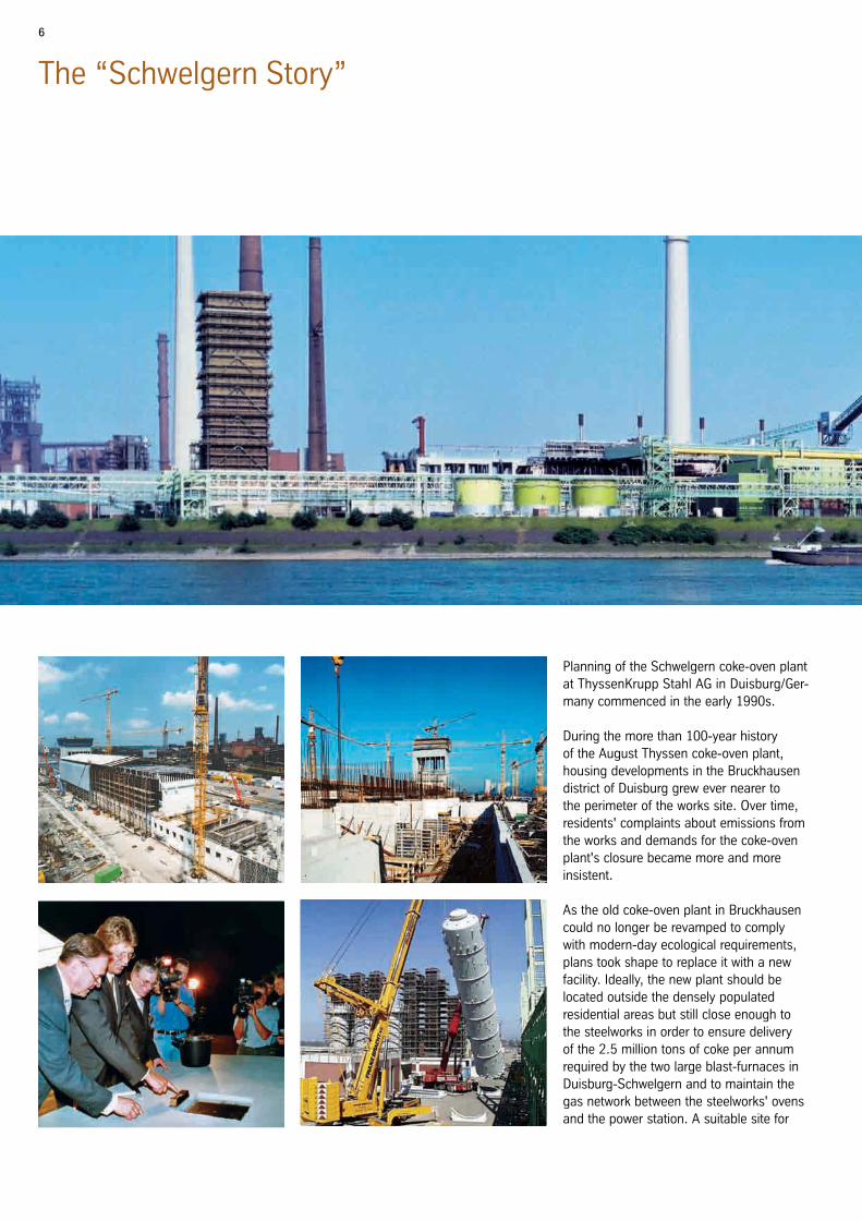
Planning of the Schwelgern coke-oven plant at ThyssenKrupp Stahl AG in Duisburg/Ger- many commenced in the early 1990s.
During the more than 100-year history of the August Thyssen coke-oven plant, housing developments in the Bruckhausen district of Duisburg grew ever nearer to the perimeter of the works site. Over time, residents' complaints about emissions from the works and demands for the coke-oven plant's closure became more and more insistent.
As the old coke-oven plant in Bruckhausen could no longer be revamped to comply with modern-day ecological requirements, plans took shape to replace it with a new facility. Ideally, the new plant should be located outside the densely populated residential areas but still close enough to the steelworks in order to ensure delivery of the 2.5 million tons of coke per annum required by the two large blast-furnaces in Duisburg-Schwelgern and to maintain the gas network between the steelworks' ovens and the power station. A suitable site for

7
the new coke-oven plant was found on the peninsula between the Schwelgern harbour and the River Rhine.
Uhde engineers were involved in the design of the Schwelgern coke-oven plant from the start. Beginning in 1996, they drew up the technical concepts on the basis of their own modern technologies for coke ovens and gas treatment plants, and compiled the neces-sary license application documents and the safety analysis.
In November 1998 the license for the pro-ject was granted, and the detail engineering commenced immediately afterwards. When the engineering phase was in full swing there were as many as 200 engineers at Uhde alone engaged in implementing the design concepts. More than 12,000 engi-neering documents were produced with the aid of state-of-the-art equipment during the 3-year engineering phase.
Within three years of the official ground-breaking in March 2000 and the laying of the foundation stone in July 2000, the
world's most modern, environmentally-friendly and, in terms of its dimensions, unique coke-oven plant took shape on the basis of engineering performed by Uhde.
Commissionin of the plant started on December 20th 2002 by heating battery 2 under the watchful eyes of our experienced technical crew. As each individual function module and plant section came on stream it justified the technical concepts selected for the plant and confirmed the successful handling of the project by the parties con-cerned, whose team spirit was exceptional. The first coke was pushed on battery 2 on March 13th 2003, some 6 weeks earlier than planned, and on battery 1 on May 21st 2003, 3 months ahead of schedule.
Using the most modern environmentally-friendly technologies and the highest pos-sible level of automation, the Schwelgern coke-oven plant achieves a production ca- pacity of 2.64 million tons of coke per an- num and 155,000 m3 coke-oven gas per hour, setting new standards world-wide.
The main milestones
09.11.1998 First notice of approval for the
construction of the Schwelgern
coke-oven plant
30.03.2000 Official groundbreaking
06.07.2000 Laying of the foundation stone
28.05.2001 Start of refractory construction
01.10.2001 Start of mechanical assembly
20.12.2002 Heating start-up
13.03.2003 First coke
8
The Coke-Oven Batteries
The challenge
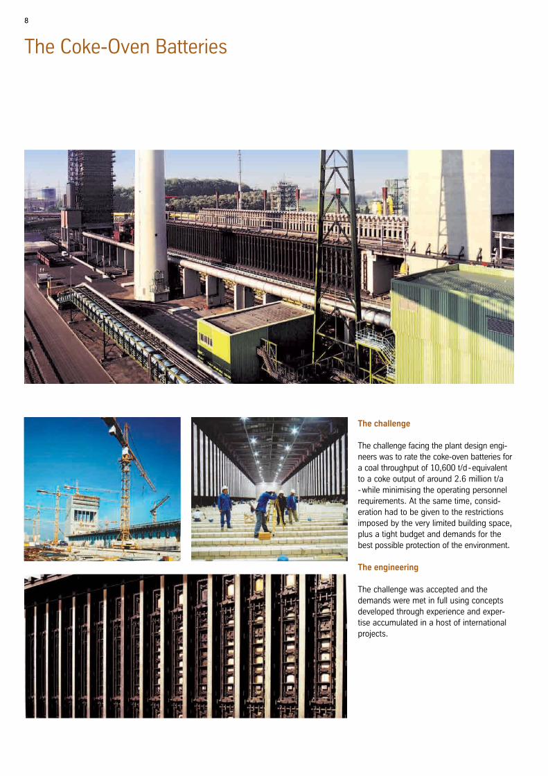
The challenge facing the plant design engi-neers was to rate the coke-oven batteries for a coal throughput of 10,600 t/d - equivalent to a coke output of around 2.6 million t/a - while minimising the operating personnel requirements. At the same time, consid-eration had to be given to the restrictions imposed by the very limited building space, plus a tight budget and demands for the best possible protection of the environment.
The engineering
The challenge was accepted and the demands were met in full using concepts developed through experience and exper-tise accumulated in a host of international projects.

9
The results
We are proud that our engineering work has resulted in a major contribution to the successful construction of a coking plant with the world's largest coke oven batter-ies. The following features are particularly noteworthy:
The large dimensions of the oven chambers allow the specified coal throughput to be achieved by only two batteries of 70 ovens each, for which relatively little space is re-quired. The necessary charging and coke-pushing operations are performed with only one set of oven servicing machines.
The well-proven CONTROLPRESS® bracing system guarantees the required pre-stress-ing and gas-tightness of the refractory walls of the very tall ovens under all operating conditions.
The batteries were heated up using spe-cially designed blower burners which can be operated over a wide control range and which ensure uniform, controlled heating of each battery refractory block.
Careful selection of suitable materials and equipment allowed the project to stay withinthe budget without detracting from the qual-ity standards required for the safe operation of the plant.
COKe TRANSFeR CAR
COKe SIDe
BATTeRy
PUSHeR SIDe
QUeNCH CAR
COKe WHARF
COAL CHARGING CAR
PUSHeR MACHINe
BATTeRy CROSS-SeCTION

10
Innovative environmental Protection at the Battery
Heating system
The heating system for low-NOx combus-
tion, which was specially designed for these large ovens, is equipped with a 3-stage air supply system. About half the combustion air enters the bottom of the heating zone through the air duct, while the other half enters the heating zone through two air ports positioned at different levels in the binder wall. The regenerator chambers are divided longitudinally in order to permit individual control of the bottom air and wall air flows. This results in an optimum vertical temperature distribution over the heating walls while reducing the NO
X content of the
exhaust gas to a very low level.
Single-chamber pressure control
The innovative PROven® system for single-chamber pressure control allows the pres-sure in each individual oven chamber to be adjusted as a function of the actual raw gas generation rate, providing the opti-mum pressure level for the given coking condition. The gas collecting main itself is operated under suction, and the pneumati-cally actuated PROven® valve controls the back-pressure in the chamber. The control system is based on the adjustment of the water level inside the PROven® valve, providing a variation of the valve port area through which the raw gas flows.
A low chamber pressure is set at the begin-ning of the coking time so that the large raw gas quantities generated in this phase are discharged without highgas pressures on the oven doors. Door and oven top emis-sions are thus prevented almost entirely.
As coking proceeds, the chamber pres-sure is gradually increased in step with the reduction in the gas generation rate inside the oven. When the gas output approaches the end of the coking process, the pressure in the oven is raised to the point where no air can be drawn in at the doors. This pro-tects the refractory walls from combustion in the end zone of the chambers, thus pro-longing the service life of the ovens.
Charging-gas aspiration
The PROven® system also ensures that the charging gases are retained within the raw gas system because the standpipes and, consequently, the oven chambers are under suction when charging takes place. Coke oven doors with an efficient sealing system and water-sealed standpipe lids are further safety measures for preventing battery emissions.

11
Pressure measurement line
Pressure controller
Pneumatic cylinder
Control valve
Fix Cup-valve: ∆H~∆P
NH3-water
Standpipe
Oven roof
Gas collecting space
GC-main
PROven® arrangement
schematic
12
Coke Stabilisation Quenching / CSQ
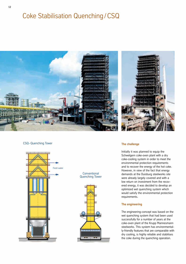
Conventional Quenching Tower
CSQ - Quenching Tower
Fresh water
The challenge
Initially it was planned to equip the Schwelgern coke-oven plant with a dry coke-cooling system in order to meet the environmental protection requirements and to recover the energy of the hot coke. However, in view of the fact that energy demands at the Duisburg steelworks site were already largely covered and with a low return on investment from the recov-ered energy, it was decided to develop an optimized wet quenching system which would satisfy the environmental protection requirements.
The engineering
The engineering-concept was based on the wet quenching system that had been used successfully for a number of years at the coke-oven plant of the Krupp Mannesmann steelworks. This system has environmental-ly-friendly features that are comparable with dry cooling, is highly reliable and stabilises the coke during the quenching operation.

13
The results
Thus the CSQ wet quenching system was developed, which is accepted as being equivalent to a dry coke-cooling system even in terms of Germany's very strict environmental protection regulations. This system consists of the following functional units:
The major portion of the quenching water is fed into the hot coke bed from below in the CSQ quenching car. The mixture of steam and water that develops in the area of contact quickly cools the coke and propels it upwards. When the coke drops again, the fine particles are separated from the coarse grain and the coke is stabilised. The formation of gaseous emissions is greatly reduced by the high cooling rate. In fact, these emissions are lower in the CSQ process than in a dry cooling system.
The CSQ quenching tower is approximately 70 m tall and has two levels of specially configured fin-shaped baffle separators for the removal of dust. The ascending vapours are also scrubbed with water and partly condensed. Particulate emissions are thus largely prevented and are lower than with a dry cooling system.
Recycled quenching water is cleaned in the quenching water settling tank. The coke breeze sediment is recycled as sintering coke.
The CSQ system, which was implemented for the first time in its complete form at the Schwelgern coke-oven plant, represents an efficient wet quenching process that pro-vides a high level of environmental perfor-mance for a relatively low investment.
CSQ quenching car

14
Gas Treatment
Clean COG
Crude COG
Crude Tar
Steam
Solids
Waste Water
Sulphur
Crude Benzene
Primary Cooling
E-FilterGas-
ExhausterH
2S/NH
3-
ScrubbingBTX-
Scrubbing
H2S/NH
3-
Desorption
Claus-Plant
BTX- Desorption
Gas Flare
Tar & Liquor Treatment
Coal Water Filter
Flushing Liquor
15
The challenge
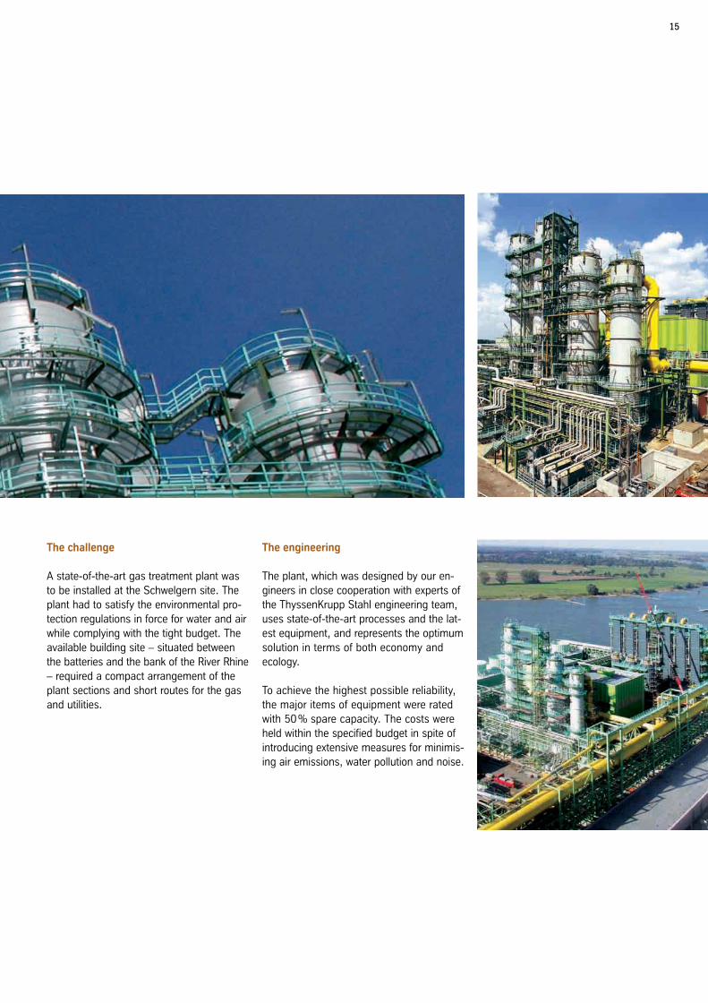
A state-of-the-art gas treatment plant was to be installed at the Schwelgern site. The plant had to satisfy the environmental pro-tection regulations in force for water and air while complying with the tight budget. The available building site – situated between the batteries and the bank of the River Rhine – required a compact arrangement of the plant sections and short routes for the gas and utilities.
The engineering
The plant, which was designed by our en-gineers in close cooperation with experts of the ThyssenKrupp Stahl engineering team, uses state-of-the-art processes and the lat-est equipment, and represents the optimum solution in terms of both economy and ecology.
To achieve the highest possible reliability, the major items of equipment were rated with 50 % spare capacity. The costs were held within the specified budget in spite of introducing extensive measures for minimis-ing air emissions, water pollution and noise.

16
Gas Treatment
The major processes
The gas pre-cooling system consists of six horizontal-tube primary coolers, four of which are in operation and two on stand-by. The raw gas from the batteries is cooled in the prima-ry coolers to approximately 24 °C. Hot water is withdrawn from the uppermost cooling stage for heating purposes. The tar content of the gas is reduced to less than 10 g/m3 (STP) by three electrostatic precipitators, two of which are in operation and one on stand-by. The gas is then compressed in the gas exhausters to a pressure of 175 mbar. One exhauster is steam-driven, the second is driven by an electric motor and the third is a standby unit provided with both types of drive.
In the tar and liquor system the condensate separated from the gas stream before it enters the pre-coolers is processed and
decanted into raw tar and water. The raw tar with a water content of less than 3% is a saleable product and is pumped to the tar tanks for intermediate storage. Solids are removed from the tar by centrifuging and are recycled to the coking coal. The surplus ammonia liquor is fed to the H
2S / NH
3 strip-
ping system for further treatment.
The gas compressed in the exhausters is cleaned in the gas scrubbers to the degree necessary for its subsequent use. The gas desulphurising system is based on the CYCLASULF® process.
In this process, which was developed by Uhde engineers, the H
2S content is reduced
to < 0.5 g/m3 (STP) and the NH3 content to
< 0.02 g/m3 (STP). The vapours stripped
in the desorption columns are processed in a COMBICLAUS® unit to produce liquid sulphur, with the ammonia being simultane-ously decomposed into its constituents N
2
and H2. The residual gases are recycled to
the raw gas mains, resulting in no emis-sions whatsoever. To fully satisfy environ-mental protection requirements, a stand-by COMBICLAUS® unit is provided.
The final scrubbing stage is the BTX scrubber where the benzene, toluene and xylene are removed from the gas to a residual content of less than 8 g/m3 (STP). At the same time, the naphthalene content is reduced to below 0.1 g/m3 (STP). After treatment in these puri-fication steps, the coke-oven gas is a valuable and environmentally friendly fuel which is exported into the steelworks gas network.

17

18
Automation
The challenge
To be able to operate the Schwelgern coke-oven plant at optimum efficiency, it was to be equipped with the latest state-of-the-art automation technology. The aim of automat-ing the process sequences was to facilitate long-term modifications required to meet environmental protection requirements.
The engineering
Uhde has been successfully engaged in the automation of coke-oven plants since 1980. The automation systems are always tailored to the customer's specific requirements, and the Schwelgern coke-oven plant is no exception. The modular design of the auto-mation systems favours this approach.
The results
To meet the challenge, the following system structure was evolved under the umbrella of the COKEMASTER® automation architec-ture:
The AutoThermTM measuring system uses its six infrared sensor heads to measure the surface temperatures of the two heat-ing walls at three different levels during each coke-pushing operation. In other words, the heating walls are thermally scanned enabling an exact overview to be obtained of the temperature distribution in each heating wall. The aim is to keep the temperature distribution in the heating walls as uniform as possible and to detect any changes.
The ManuThermTM system is an infrared pyrometer with integral data memory for taking manual measurements at the heat-ing flues. Its main job is to measure heating flue temperatures when no AutothermTM measurements are available, for instance when no coke-pushing is taking place for operational reasons. Also, detailed spot measurements can be taken where heating problems have been detected by AutoThermTM. These temperature measure-ments are fed into the computer system and can be used for further calculations and evaluations.
The BatControlTM system calculates the amount of heat required for the battery,
ManuThermTM
Heating flue temperatures
Heating flue temperatures
Oven wall temperatures
Pushing forces
Operator station
control roomCoordination PCL for oven machines
Handheld pyrometer
Pusher machineCoke
transfer car
Coal quench
car
Coal charging
car
PushSchedTM
Scheduling of oven machines
Scheduling of oven machines
AutoThermTM
Oven wall temperatures
RamForceTM
Pushing forces
BatControlTM
Heat quantity control
DCS
Process data
Heat quantity control
Level 2 process computer/batteryAutomation system
for battery operation
MainControlTM
SimuGasTM
GasControlTM
PushSchedTM
AutoThermTM
ManuThermTM
SimuCokeTM
BatControlTM
CokeControlTM
CoalControlTM
COKEmASTEr®
19
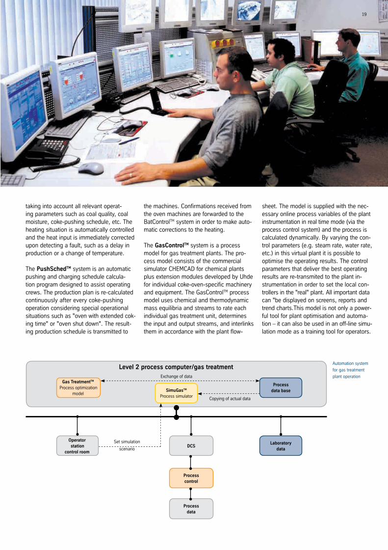
taking into account all relevant operat-ing parameters such as coal quality, coal moisture, coke-pushing schedule, etc. The heating situation is automatically controlled and the heat input is immediately corrected upon detecting a fault, such as a delay in production or a change of temperature.
The PushSchedTM system is an automatic pushing and charging schedule calcula-tion program designed to assist operating crews. The production plan is re-calculated continuously after every coke-pushing operation considering special operational situations such as "oven with extended cok-ing time" or "oven shut down". The result-ing production schedule is transmitted to
the machines. Confirmations received from the oven machines are forwarded to the BatControlTM system in order to make auto-matic corrections to the heating.
The GasControlTM system is a process model for gas treatment plants. The pro-cess model consists of the commercial simulator CHeMCAD for chemical plants plus extension modules developed by Uhde for individual coke-oven-specific machinery and equipment. The GasControlTM process model uses chemical and thermodynamic mass equilibria and streams to rate each individual gas treatment unit, determines the input and output streams, and interlinks them in accordance with the plant flow-
sheet. The model is supplied with the nec-essary online process variables of the plant instrumentation in real time mode (via the process control system) and the process is calculated dynamically. By varying the con-trol parameters (e.g. steam rate, water rate, etc.) in this virtual plant it is possible to optimise the operating results. The control parameters that deliver the best operating results are re-transmited to the plant in- strumentation in order to set the local con- trollers in the "real" plant. All important data can "be displayed on screens, reports and trend charts.This model is not only a power- ful tool for plant optimisation and automa-tion – it can also be used in an off-line simu- lation mode as a training tool for operators.
Operator station
control room
Process data base
Copying of actual data
Set simulation
scenario
exchange of data
Laboratory data
SimuGasTM
Process simulator
Gas TreatmentTM
Process optimization model
DCS
Process data
Process control
Level 2 process computer/gas treatmentAutomation system
for gas treatment
plant operation

2
CP
300/
1500
e 01
/201
2 Th
ysse
nKru
pp U
hde/
TK
prin
tmed
ia/P
rinte
d in
Ger
man
y
ThyssenKrupp Uhde
Friedrich-Uhde-Strasse 15
44141 Dortmund, Germany
Tel.: +49 231 5 47-0 · Fax: +49 231 5 47-30 32 · www.uhde.eu