3-point stepper control with pid 3step - siemens ag & tools answers for industry. cover 3-point...
TRANSCRIPT

Applications & Tools
Answers for industry.
Cover
3-Point Stepper Control with PID 3Step
SIMATIC S7-1500
Application Description May 2013

2 3-point stepper control with PID 3Step
1.0 , Entry ID: 68011827
Cop
yrig
ht
Sie
men
s AG
201
3 Al
l rig
hts
rese
rved
Siemens Industry Online Support This entry is taken from Siemens Industry Online Support. The following link takes you directly to the download page of this document: http://support.automation.siemens.com/WW/view/en/68011827 Caution The functions and solutions described in this article confine themselves to the realization of the automation task predominantly. Please take into account furthermore that corresponding protective measures have to be taken up in the context of Industrial Security when connecting your equipment to other parts of the plant, the enterprise network or the Internet. Further information can be found under the Entry ID 50203404. http://support.automation.siemens.com/WW/view/en/50203404

3-point stepper control with PID 3Step 1.0 , Entry ID: 68011827 3
Cop
yrig
ht
Sie
men
s AG
201
3 Al
l rig
hts
rese
rved
s
SIMATIC S7-1500 3-point stepper control with PID 3Step PID_3Step Technology Object
Task 1
Solution 2
Basics 3
Function Mechanisms of this Application
4
Startup of the Application 5
Operating the Application 6
Internet Links 7
History 8
Warranty and Liability
4 3-point stepper control with PID 3Step
1.0 , Entry ID: 68011827
Cop
yrig
ht
Sie
men
s AG
201
3 Al
l rig
hts
rese
rved
Warranty and Liability
Note The Application Examples are not binding and do not claim to be complete regarding the circuits shown, equipping and any eventuality. The Application Examples do not represent customer-specific solutions. They are only intended to provide support for typical applications. You are responsible for ensuring that the described products are used correctly. These application examples do not relieve you of the responsibility to use safe practices in application, installation, operation and maintenance. When using these Application Examples, you recognize that we cannot be made liable for any damage/claims beyond the liability clause described. We reserve the right to make changes to these Application Examples at any time without prior notice. If there are any deviations between the recommendations provided in these application examples and other Siemens publications – e.g. Catalogs – the contents of the other documents have priority.
We do not accept any liability for the information contained in this document.
Any claims against us – based on whatever legal reason – resulting from the use of the examples, information, programs, engineering and performance data etc., described in this Application Example shall be excluded. Such an exclusion shall not apply in the case of mandatory liability, e.g. under the German Product Liability Act (“Produkthaftungsgesetz”), in case of intent, gross negligence, or injury of life, body or health, guarantee for the quality of a product, fraudulent concealment of a deficiency or breach of a condition which goes to the root of the contract (“wesentliche Vertragspflichten”). The damages for a breach of a substantial contractual obligation are, however, limited to the foreseeable damage, typical for the type of contract, except in the event of intent or gross negligence or injury to life, body or health. The above provisions do not imply a change of the burden of proof to your detriment. Any form of duplication or distribution of these Application Examples or excerpts hereof is prohibited without the expressed consent of Siemens Industry Sector.

Preface
3-point stepper control with PID 3Step 1.0 , Entry ID: 68011827 5
Cop
yrig
ht
Sie
men
s AG
201
3 Al
l rig
hts
rese
rved
Preface Objective of the application
The application on hand uses the example of a mixer to illustrate the application of the integrated 3-point stepper control of the S7-1500 automation system.
Core topics of this application The following main points are discussed in this application: • Configuring the 3-point stepper controller • Programming the 3-point stepper controller • Commissioning the 3-point stepper controller • Operating the 3-point stepper controller via a control panel
Advantage The application of the (TO) PID_3Step technology object has many advantages. • PID control
– Simple programming with configurable blocks. – Simple commissioning through automatic calculation of the control
parameters for optimal control quality and clear signal monitoring with trace function. Additional support by automatic transition time measurement of the actuator.
• Integrated PID control Specialized stepper controller for integrated actuators (e.g. valves).
• Auto tuning Innovative auto tuning with two different tuning methods for automatic calculation of the control parameters: pretuning and fine tuning during runtime.
The same advantages also apply for the PID_Compact (controller for continuous controlled systems).
Benefits • No additional hardware and software required. • Time saving due to simple automatic control parameter optimization for optimal
control quality (PID controller).

Table of Contents
6 3-point stepper control with PID 3Step
1.0 , Entry ID: 68011827
Cop
yrig
ht
Sie
men
s AG
201
3 Al
l rig
hts
rese
rved
Table of Contents Warranty and Liability ................................................................................................. 4
Preface .......................................................................................................................... 5 Table of Contents ......................................................................................................... 6
1 Task ..................................................................................................................... 7
1.1 Overview............................................................................................... 7 2 Solution............................................................................................................... 8
2.1 Solution overview ................................................................................. 8 2.2 Description of the core functionality ................................................... 11 2.3 Hardware and software components used......................................... 13
3 Basics ............................................................................................................... 15
4 Function Mechanisms of this Application .................................................... 16
4.1 Main [OB1] ......................................................................................... 17 4.1.1 HMI [FC7] ........................................................................................... 17 4.1.2 Simulation_Main [FC1] ....................................................................... 17 4.2 Cyclic interrupt [OB30] ....................................................................... 18 4.2.1 Switch [FC4] ....................................................................................... 19
Scale_Int2Real [FC3] ......................................................................... 20 4.2.2 PID_3Step [FB1131] .......................................................................... 21 4.2.3 Simulation_OB30 [FC2] ...................................................................... 23
VALVE [FB101] .................................................................................. 23 Scale_Real2Real [FC6] ...................................................................... 25 PROC_C [FB100] ............................................................................... 26 Scale_ Real2Int [FC5] ........................................................................ 27
5 Startup of the Application ............................................................................... 29
5.1 Hardware adaptation .......................................................................... 29 5.1.1 Input signal ......................................................................................... 29 5.1.2 Output signal ...................................................................................... 29 5.2 Configuration instructions ................................................................... 31 5.3 Commissioning the 3-point stepper controller .................................... 37 5.4 HMI project part .................................................................................. 40
6 Operating the Application ............................................................................... 43
6.1 Overview of the application-specific screens ..................................... 44 6.1.1 Start screen ........................................................................................ 44 6.1.2 Support description ............................................................................ 44 6.1.3 Overview screen ................................................................................. 45 6.1.4 Operating screen ................................................................................ 46 6.1.5 System functions ................................................................................ 47 6.2 Overview of application-specific screens ........................................... 48 6.2.1 Mixer tap ............................................................................................. 49 6.2.2 Trend view .......................................................................................... 52 6.2.3 Tuning................................................................................................. 53 6.2.4 Monitoring ........................................................................................... 55 6.2.5 Configuration ...................................................................................... 56 6.2.6 Simulation ........................................................................................... 57
7 Internet Links ................................................................................................... 58
8 History............................................................................................................... 58
1 Task
3-point stepper control with PID 3Step 1.0 , Entry ID: 68011827 7
Cop
yrig
ht
Sie
men
s AG
201
3 Al
l rig
hts
rese
rved
1 Task 1.1 Overview
Introduction The "PID_3Step" controller block shall control the valve of a mixer tap according to a desired given temperature.
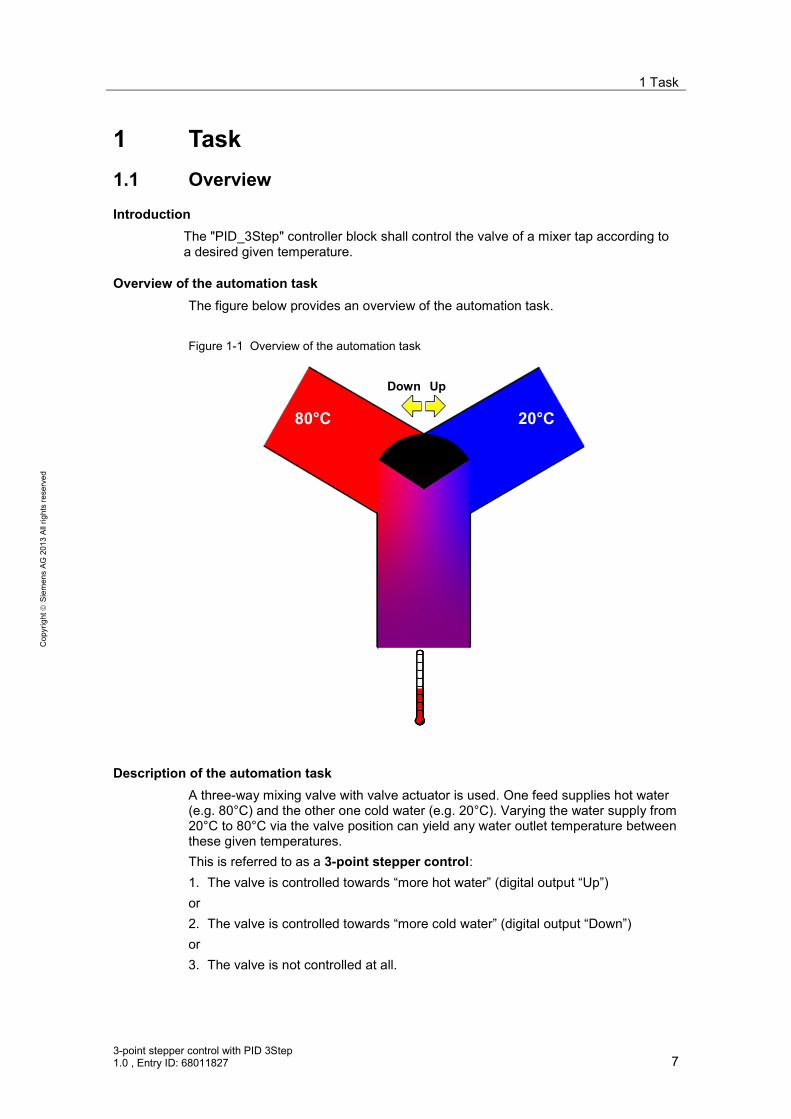
Overview of the automation task The figure below provides an overview of the automation task. Figure 1-1 Overview of the automation task
80°C 20°C
UpDown
Description of the automation task A three-way mixing valve with valve actuator is used. One feed supplies hot water (e.g. 80°C) and the other one cold water (e.g. 20°C). Varying the water supply from 20°C to 80°C via the valve position can yield any water outlet temperature between these given temperatures. This is referred to as a 3-point stepper control: 1. The valve is controlled towards “more hot water” (digital output “Up”) or 2. The valve is controlled towards “more cold water” (digital output “Down”) or 3. The valve is not controlled at all.

2 Solution
8 3-point stepper control with PID 3Step
1.0 , Entry ID: 68011827
Cop
yrig
ht
Sie
men
s AG
201
3 Al
l rig
hts
rese
rved
2 Solution 2.1 Solution overview
For SIMATIC S7-1500, the development environment STEP 7 V12 provides the “PID_3Step” 3-point stepper control block. This instruction was especially developed for controlling valves or actuators with integrated behavior. It offers a simple and quick configuration and commissioning of your 3-point stepper control application.
Schematic layout The following figure displays the most important components of the solution: Figure 2-1 Overview of the overall solution
UpDown
High LimitLow Limit
Process value
Feedback
KTP1000 Basic PN
CPU 1211C
Within a control loop (here the mixer tap), the “PID_3Step” technology object continuously detects the measured actual value (the “Process value” temperature) and compares this value with the setpoint value (given via the TP1500 Comfort). From the resulting control deviation, PID_3Step calculates an output value which enables the actual value to reach the setpoint value as quickly and stable as possible. The output value is converted into the digital control of the valve (“Up”/“Down”).

2 Solution
3-point stepper control with PID 3Step 1.0 , Entry ID: 68011827 9
Cop
yrig
ht
Sie
men
s AG
201
3 Al
l rig
hts
rese
rved
The output value of the PID controller is composed of the following fractions: • P fraction
The P fraction of the output value rises proportionally to the control deviation. • I fraction
The I fraction of the output value rises as long as the control deviation is balanced.
• D-fraction The D-fraction rises with increasing modification speed of the control deviation. The actual value is adapted to the setpoint value as quickly as possible. If the modification speed of the control deviation decreases again, the D-fraction also decreases.
• Derivative time lag coefficient The effect of the D fraction is delayed by the derivative time lag coefficient. Derivative time lag = Derivative time x Derivative time lag coefficient – 0.0: the D fraction is only effective for one cycle, hence, it is virtually
ineffective – 0.5: in practice, this value has proven itself for controlled systems with a
dominating time constant. – > 1.0: the larger the coefficient, the more the effect of the D fraction is
delayed • Weighting of the P fraction
You can weaken the P fraction for setpoint value changes. Values from 0.0 to 1.0 are sensible – 1.0: P fraction fully effective at a setpoint value change – 0.0: P fraction not effective at a setpoint value change When changing the actual value, the P fraction is always fully effective.
• Weighting of the D fraction You can weaken the D fraction for setpoint value changes. Values from 0.0 to 1.0 are sensible – 1.0: D fraction fully effective at a setpoint value change – 0.0: D fraction not effective at a setpoint value change When changing the actual value, the D fraction is always fully effective.
• PID algorithm scan time Since the controlled system requires a certain time to react to a changed output value, it is sensible to not calculate the output value for each cycle. The PID algorithm scan time is the time between two output value calculations: It is determined during the optimization and rounded to a multiple of the scan time of the PID_3Step scan time. All other functions of PID_3Step are performed each time it is called up.
• Deadband width The dead band suppresses the noise fraction in the steady controller state. The deadband width specifies the size of the deadband. At a deadband width of 0.0 the dead band is switched off.
The “PID_3Step” instruction automatically calculates the P, I, and D parameters for your controlled system during pretuning. The parameters can be further optimized via fine tuning. You need not determine the parameters manually.

2 Solution
10 3-point stepper control with PID 3Step
1.0 , Entry ID: 68011827
Cop
yrig
ht
Sie
men
s AG
201
3 Al
l rig
hts
rese
rved
The 3-point stepper control is configured as follows: • without end position feedback or valve position feedback • with end position feedback of the valve only (Low & High Limit) • with valve position feedback only (Feedback) • with end position and valve position feedback
Note For more information on PID_3Step and PID_Compact refer to the Online Help of the TIA Portal.

2 Solution
3-point stepper control with PID 3Step 1.0 , Entry ID: 68011827 11
Cop
yrig
ht
Sie
men
s AG
201
3 Al
l rig
hts
rese
rved
2.2 Description of the core functionality
The core functionality of the application lies in the operation of the “PID_3Step” 3-point stepper controller via an HMI.
Overview and description of the user interface Figure 2-2 Overview and description of the user interface
Mixer tap Trend view Tuning
Monitoring Configuration Simulation
The operation of the application consists of the following 6 pictures: • Mixer tap • Trend view • Tuning • Monitoring • Configuration • Simulation The operation of the screens is described in greater detail in chapter 6.

2 Solution
12 3-point stepper control with PID 3Step
1.0 , Entry ID: 68011827
Cop
yrig
ht
Sie
men
s AG
201
3 Al
l rig
hts
rese
rved
Advantages of this solution The application enables you to use any configuration options and startup features via a TP1500 Comfort operator panel or via the HMI simulation integrated in WinCC V12 Basic. This application offers you the following advantages: • Switching between automatic and manual mode • Transition time measurement of the valve • Visualization of the valve position • Trend curves of setpoint, actual value and manipulated variable • Switching between the real controlled system and the simulation • Disturbance variable control in simulation mode • Specifying the behavior in the case of errors and their simulation • Specifying the dead band width for energy saving operation • Manually specified control parameter and automatic tuning • Online monitoring of the “PID_3Step” controller block • Modifying the configuration during runtime
Delimitation This application gives you an overview of the “PID_3Step” technology object for operating a 3-point stepper controller via SIMATIC S7-1500 CPU. You can adopt the application example to adjust your 3-point stepper control conveniently via TP1500 Comfort and adapt it to your automation task. The application was tested via the simulation of the controlled system. For the actual operation, the application example must be adapted to your used valve with actuator and temperature sensors used: • Digital control in 2 directions or analog control? • Required voltage and output for the control? • Signal properties when feeding back the valve position or recorded end
positions? • Signal properties of the used temperature sensor? The application is no substitute for the configuration screen of the PID_3Step wizard, since it defines the default values in the instance data block which are decisive for the restart after a power failure. Apart from the “PID_3Step” control block, STEP 7 V12 also provides the “PID_Compact” for the SIMATIC S7-1500. This is a universally usable PID controller for continuous controlled systems. It also contains the advantages of automatic tuning, as well as the operating modes automatic and manual. According to the template of this application example, an HMI user interface can also be designed for the “PID_Compact”.
Required knowledge Basic knowledge of control engineering and STEP 7 programming is assumed.

2 Solution
3-point stepper control with PID 3Step 1.0 , Entry ID: 68011827 13
Cop
yrig
ht
Sie
men
s AG
201
3 Al
l rig
hts
rese
rved
2.3 Hardware and software components used
The application was set up with the following components:
Hardware components Table 2-1
Component No. Order number Note
SIMATIC HMI TP1500 Comfort
1 6AV6647-0AF11-3AX0 Optional (can also be simulated via WinCC V12)
DI 32 1 6ES7 521-1BL00-0AB0 DQ 32 1 6ES7 522-1BL00-0AB0 AI 8 1 6ES7 531-7KF00-0AB0 AQ 4 1 6ES7 532-5HD00-0AB0 optional POWER SUPPLY DC28W
1 6ES7 505-0KA00-0AB0
CPU S7-1516 3PN/DP 1 6ES7516-3AN00-0AB0
or alternatively a CPU S7-1511 or S7-1513
Three-way mixing valve with actuator motor and control for 2 directions
1 Valve manufacturer Optional with digital end position feedback or analog valve position feedback (0 to 10V)
Temperature sensors protection class: IPX8 (permanent submersion) measuring range: 0 to 100°C
1 Electrical goods retailer Executable as analog signal encoder, thermocouple or resistivity thermometer
Programming unit 1 With Ethernet connector Ethernet line TP CORD RJ45/RJ45 2M
3 6XV1870-3QH20
Miniature circuit breaker 1 5SX2116-6 1 pole B, 16A S7-1500 mounting rail 482 mm
1 6ES7 590-1AE80-0AA0
2 Solution
14 3-point stepper control with PID 3Step
1.0 , Entry ID: 68011827
Cop
yrig
ht
Sie
men
s AG
201
3 Al
l rig
hts
rese
rved
Standard software components Table 2-2
Component No. Order number Note
SIMATIC STEP 7 V12 1 6ES7822-1A.02-.. SIMATIC WinCC V12 1 6AV210.-....2-0
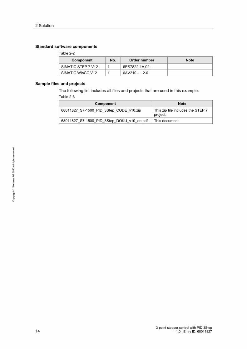
Sample files and projects The following list includes all files and projects that are used in this example. Table 2-3
Component Note
68011827_S7-1500_PID_3Step_CODE_v10.zip This zip file includes the STEP 7 project.
68011827_S7-1500_PID_3Step_DOKU_v10_en.pdf This document

3 Basics
3-point stepper control with PID 3Step 1.0 , Entry ID: 68011827 15
Cop
yrig
ht
Sie
men
s AG
201
3 Al
l rig
hts
rese
rved
3 Basics Overview of data management
Figure 3-1 shows an overview of the data management of the “PID_3Step” controller. • For the PID Control technology objects start values are created for the PID
parameters. The start values can be edited. • During the download into the CPU, the offline project is first stored in the load
memory. • For the operating status transitions NETWORK ON Startup and for STOP
Startup the variables of global data blocks, instance data blocks and technology objects are initialized with your start values. Retentive tags receive their actual values secured in the retentive memory.
• Tuning the PID parameters affects the actual values in the work memory. • The “Monitoring / control” function also accesses the current values in the main
memory. • Clicking on the “Upload PID parameters” icon loads the tuned PID parameters
into your offline project.
Figure 3-1 Data management overview
Offline Project
Load memory Work memory
Start value
„TO PID_3Step“
S7-1500
Actual value
„TO PID_3Step“
„TO PID_3Step“
InitializationLoad to PG
Monitoring/Modify
Monitoring
Start Tuning
Edit start value
Start value
Load to PLC
Retentive
mem
ory
STOP
RUN

4 Function Mechanisms of this Application
16 3-point stepper control with PID 3Step
1.0 , Entry ID: 68011827
Cop
yrig
ht
Sie
men
s AG
201
3 Al
l rig
hts
rese
rved
4 Function Mechanisms of this Application General overview
Figure 4-1 shows the temporal sequence of block calls in the control unit of the application project. Figure 4-1 Program structure overview
Startup [OB100]
Main[OB1]
Cyclicinterrupt[OB30]
T =100 ms
Simulation_Main[FC1]
Switch[FC4]
Scale_Int2Real[FC3]
Simulation_OB30[FC2]
PID_3Step [FB1131]PID_3Step_1 [DB1]
VALVE [FB101]VALVE_DB [DB2]
Scale_Real2Real[FC6]
PROG_C [FB100]PROG_C_DB [DB3]
Scale_Real2Int[FC5]
Scale_Int2Real[FC3]
HMI[FC7]
The control project part uses the following organization blocks: • Startup [OB100] for initialization • Main [OB1], from where the functions for the HMI transfer are called • Cyclic interrupt [OB30], which calls the 3-point stepper controller cyclically
every 100 milliseconds using the simulation blocks. Instance data bocks and global data blocks are used for the parameter transfer between the functions. Instance data blocks: • PID_3Step_1 [DB1] • VALVE_DB [DB2] • PROG_C_DB [DB3]
Global data blocks: • Tags [DB4] (contains all tags not required for the simulation of the controlled
system) • Simulation_tags [DB4] (contains all tags required for the simulation of the
controlled system).

4 Function Mechanisms of this Application
3-point stepper control with PID 3Step 1.0 , Entry ID: 68011827 17
Cop
yrig
ht
Sie
men
s AG
201
3 Al
l rig
hts
rese
rved
4.1 Main [OB1]
The functions for the HMI transfer are called from the operation block “Main”.
4.1.1 HMI [FC7]
Figure 4-2 Calling the “HMI” function
The “HMI” function defines tags which the TP1500 Comfort requires for the display, such as: • Visibility tags • Synchronization times • Value transfers • Feasibility conditions Further descriptions are available in the network headers.
4.1.2 Simulation_Main [FC1]
Figure 4-3 Call of function “Simulation_Main”
The “Simulation_Main” function defines tags required for the simulation of the controlled system, such as: • disturbance variables • referencing • visibility of simulation tags Further descriptions are available in the network headers.
4 Function Mechanisms of this Application
18 3-point stepper control with PID 3Step
1.0 , Entry ID: 68011827
Cop
yrig
ht
Sie
men
s AG
201
3 Al
l rig
hts
rese
rved
4.2 Cyclic interrupt [OB30]
The actual program (the call of the “PID_3Step” 3-point stepper controller) occurs in the cyclic interrupt OB, since discrete software controls must be called up in a defined time interval for optimizing the controller quality. 100ms were set as a constant time interval for the scan time of OB30.
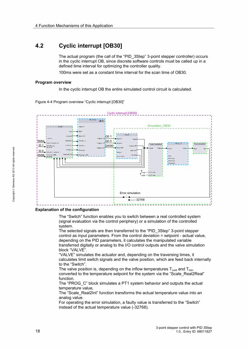
Program overview In the cyclic interrupt OB the entire simulated control circuit is calculated.
Figure 4-4 Program overview “Cyclic interrupt [OB30]”
Q0.1Q0.0QW80
ThotTcold
I0.1
I0.0
IW64
IW66
-32768
Error simulation
Simulation_OB30
Cyclic interrupt [OB30]
Explanation of the configuration The “Switch” function enables you to switch between a real controlled system (signal evaluation via the control periphery) or a simulation of the controlled system. The selected signals are then transferred to the “PID_3Step” 3-point stepper control as input parameters. From the control deviation = setpoint - actual value, depending on the PID parameters, it calculates the manipulated variable transferred digitally or analog to the I/O control outputs and the valve simulation block “VALVE”. “VALVE” simulates the actuator and, depending on the traversing times, it calculates limit switch signals and the valve position, which are feed back internally to the “Switch”. The valve position is, depending on the inflow temperatures Tcold and Thot, converted to the temperature setpoint for the system via the “Scale_Real2Real” function. The “PROG_C” block simulates a PT1 system behavior and outputs the actual temperature value, The “Scale_Real2Int” function transforms the actual temperature value into an analog value. For operating the error simulation, a faulty value is transferred to the “Switch” instead of the actual temperature value (-32768).

4 Function Mechanisms of this Application
3-point stepper control with PID 3Step 1.0 , Entry ID: 68011827 19
Cop
yrig
ht
Sie
men
s AG
201
3 Al
l rig
hts
rese
rved
4.2.1 Switch [FC4]
The “Switch” function is used for switching between the signal evaluation via the control I/O and internally calculated simulated input signals for transfer at the “PID_3Step” 3-point stepper control. Figure 4-5 Calling the “Switch” function
Table 4-1
Name Data type
Description
Input simulate Bool FALSE = input parameter TRUE = internal simulation parameters are transferred to the outputs
Input_PER_physical Int Analog I/O input signal for the actual value Actuator_H_physical Bool Upper limit switch signal of the valve Actuator_L_physical Bool Lower limit switch signal of the valve Feedback_PER_physical Int Analog I/O input signal for the valve position
feedback Output Input Real Process value transfer to PID_3Step
Input_PER Int Analog process value transfer to PID_3Step Actuator_H Bool Transfer of the upper limit switch signal to
PID_3Step Actuator_L Bool Transfer of the lower limit switch signal to
PID_3Step Feedback Real Transfer of the valve position feedback to
PID_3Step Feedback_PER Int Transfer of the analog valve position feedback to
PID_3Step

4 Function Mechanisms of this Application
20 3-point stepper control with PID 3Step
1.0 , Entry ID: 68011827
Cop
yrig
ht
Sie
men
s AG
201
3 Al
l rig
hts
rese
rved
Note Assign all inputs. This also applies if due to your controller configuration you do not need all of the inputs.
The simulated input variables are deliberately not directed outwards, since you only need to adjust the real I/O inputs to its hardware configuration.
For “simulate” = FALSE, the “Input” and “Feedback” parameters are calculated from the analog values “Input_PER” and “Feedback_PER” using the “Scale_Int2Real” function.
Scale_Int2Real [FC3] The “Scale_Int2Real” function in function block “Switch” is used for converting an analog value (data type: Int) into a floating-point number (data type: Real) within predefined limits. Figure 4-6 Calling the “Scale_Int2Real” function
Table 4-2
Name Data type Description
Input Int Int Analog value to be converted Int_max Real Upper limit of the analog value Int_min Real Lower limit of the analog value Real_max Real Upper limit of the floating-point output value Real_min Real Lower limit of the floating-point output value
Output Real Real Floating-point output value

4 Function Mechanisms of this Application
3-point stepper control with PID 3Step 1.0 , Entry ID: 68011827 21
Cop
yrig
ht
Sie
men
s AG
201
3 Al
l rig
hts
rese
rved
Note The specified input limits “Int_max” and “Int_min” are intentionally defined as “Real”, in order to guarantee the compatibility with the specified limits in the instance data block of “PID_3Step”.
4.2.2 PID_3Step [FB1131]
STEP 7 V12 provides the “PID_3Step” technology object with the installation. This function block was especially developed for controlling valves or actuators with integrated behavior. Figure 4-7 Calling function block “PID_3Step”
Table 4-3
Name Data type Description
Input Setpoint Real Internal setpoint value Input Real Actual value in REAL format Input_PER Word Actual value in I/O format Actuator_H Bool Actuator upper end stop Actuator_L Bool Actuator lower end stop Feedback Real External position feedback in REAL format
4 Function Mechanisms of this Application
22 3-point stepper control with PID 3Step
1.0 , Entry ID: 68011827
Cop
yrig
ht
Sie
men
s AG
201
3 Al
l rig
hts
rese
rved
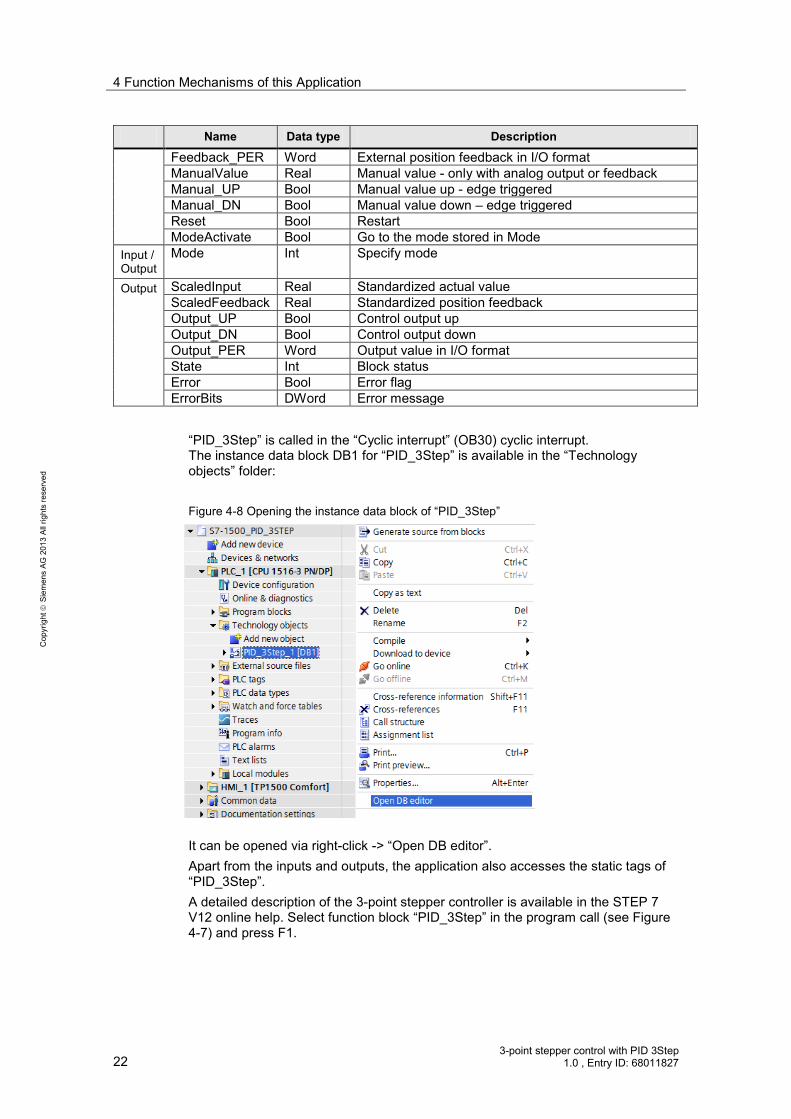
Name Data type Description
Feedback_PER Word External position feedback in I/O format ManualValue Real Manual value - only with analog output or feedback Manual_UP Bool Manual value up - edge triggered Manual_DN Bool Manual value down – edge triggered Reset Bool Restart ModeActivate Bool Go to the mode stored in Mode
Input / Output
Mode Int Specify mode
Output ScaledInput Real Standardized actual value ScaledFeedback Real Standardized position feedback Output_UP Bool Control output up Output_DN Bool Control output down Output_PER Word Output value in I/O format State Int Block status Error Bool Error flag ErrorBits DWord Error message
“PID_3Step” is called in the “Cyclic interrupt” (OB30) cyclic interrupt. The instance data block DB1 for “PID_3Step” is available in the “Technology objects” folder: Figure 4-8 Opening the instance data block of “PID_3Step”
It can be opened via right-click -> “Open DB editor”. Apart from the inputs and outputs, the application also accesses the static tags of “PID_3Step”. A detailed description of the 3-point stepper controller is available in the STEP 7 V12 online help. Select function block “PID_3Step” in the program call (see Figure 4-7) and press F1.

4 Function Mechanisms of this Application
3-point stepper control with PID 3Step 1.0 , Entry ID: 68011827 23
Cop
yrig
ht
Sie
men
s AG
201
3 Al
l rig
hts
rese
rved
4.2.3 Simulation_OB30 [FC2]
All functions are called from the “Simulation_ OB30” function required for the simulation of the controlled system: • VALVE [FB101] • Scale_Real2Real [FC6] • PROC_C [FB100] • Scale_ Real2Int [FC5] The “Simulation_OB30” is called in the same cyclic interrupt as the 3-point stepper controller “PID_3Step”. For more information, please refer to the following description. Figure 4-9 Call of function “Simulation_OB30”
VALVE [FB101] The “VALVE” function block simulates the actuator and, depending on the traversing time, it calculates the valve position and sets the limit switch signals Depending on the “PER_on” input setting, the valve position is calculated from the digital control signals “InputUP” and “InputDN” or from the analog manipulated variable “Input_PER” of the “PID_3Step” 3-point stepper controller. The limits for converting the valve position between analog value and floating-point number are adopted from the instance data block of “PID_3Step”. The specified input limits “PER_max” and “PER_min” are intentionally defined as “Real”, in order to guarantee the compatibility with the specified limits in the instance data block of “PID_3Step”. When activating the “Reset” input, the calculation of the valve position starts at the lower end position.

4 Function Mechanisms of this Application
24 3-point stepper control with PID 3Step
1.0 , Entry ID: 68011827
Cop
yrig
ht
Sie
men
s AG
201
3 Al
l rig
hts
rese
rved
Figure 4-10 Calling function block “VALVE_DB”
Table 4-4
Name Data type Description
Input InputUP Bool Control signal “Open valve” InputDN Bool Control signal “Close valve” Input_PER Int Analog manipulated variable of PID_3Step PER_on Bool Selection switch, whether InputUP/InputDN or Input_PER
is used (Input_PER is used for TRUE) PER_max Real Upper limit of the analog value of the valve position PER_min Real Lower limit of the analog value of the valve position Real_max Real Upper limit of the converted floating-point value for the
valve position Real_min Real Lower limit of the converted floating-point value for the
valve position

4 Function Mechanisms of this Application
3-point stepper control with PID 3Step 1.0 , Entry ID: 68011827 25
Cop
yrig
ht
Sie
men
s AG
201
3 Al
l rig
hts
rese
rved
Name Data type Description
TransitTime Real Traversing time of the value between the end positions Cycle Real Call interval of the cyclic interrupt Reset Bool Input for the reset
Output Output Real Calculated valve position (within the “Real_min” and “Real_max” limits)
Output_PER Int Calculated analog valve position (within the “PER_min” and “PER_max” limits)
HighLimit Bool Simulated upper valve end position LowLimit Bool Simulated lower valve end position
Scale_Real2Real [FC6] The “Scale_Real2Real” function is used for converting a floating-point number (data type: Real) into a different floating-point number (data type: Real) within predefined boundaries. This function is used for converting the simulated valve position in the temperature setpoint value as input parameter for the PT1 controlled system simulation. This temperature setpoint value must be converted to the limits of the water feed into the mixer tap. Figure 4-11 Calling the “Scale_Real2Real” function

4 Function Mechanisms of this Application
26 3-point stepper control with PID 3Step
1.0 , Entry ID: 68011827
Cop
yrig
ht
Sie
men
s AG
201
3 Al
l rig
hts
rese
rved
Table 4-5
Name Data type Description
Input Input Real Floating-point value to be converted IN_max Real Upper limit of the floating point input value IN_min Real Lower limit of the floating point input value OUT_max Real Upper limit of the floating point output value OUT_min Real Lower limit of the floating point output value
Output Real Real Foating point output value
PROC_C [FB100] Function block “PROC_C” simulates the continuous behavior of a controlled system PT3. Calculation of the output value is based on the following formula:
OffsetsTimeLagsTimeLagsTimeLag
eDisturbancInputGainOutput ++⋅⋅+⋅⋅+⋅
+⋅=
)13()12()11()(
s = Laplace operator In the application on hand, controlled system simulation block “PROC_C” is designed as controlled system PT1 with a delay time of 10 seconds (“TimeLag2” and “TimeLag3” are disabled). Figure 4-12 Calling function block “PROC_C”

4 Function Mechanisms of this Application
3-point stepper control with PID 3Step 1.0 , Entry ID: 68011827 27
Cop
yrig
ht
Sie
men
s AG
201
3 Al
l rig
hts
rese
rved
Table 4-6
Name Data type Description
Input Input Real Input value of the simulation of the controlled system Disturbance Real Disturbance variable Offset Real Output offset Gain Real Gain factor TimeLag1 Real Delay time 1 (deactivation for TimeLag1=0.0) TimeLag2 Real Delay time 2 (deactivation for TimeLag2=0.0) TimeLag3 Real Delay time 3 (deactivation for TimeLag3=0.0) Cycle Real Call interval of the cyclic interrupt Reset Bool Input for the reset
Output Output Real Calculated output value of the controlled system simulation
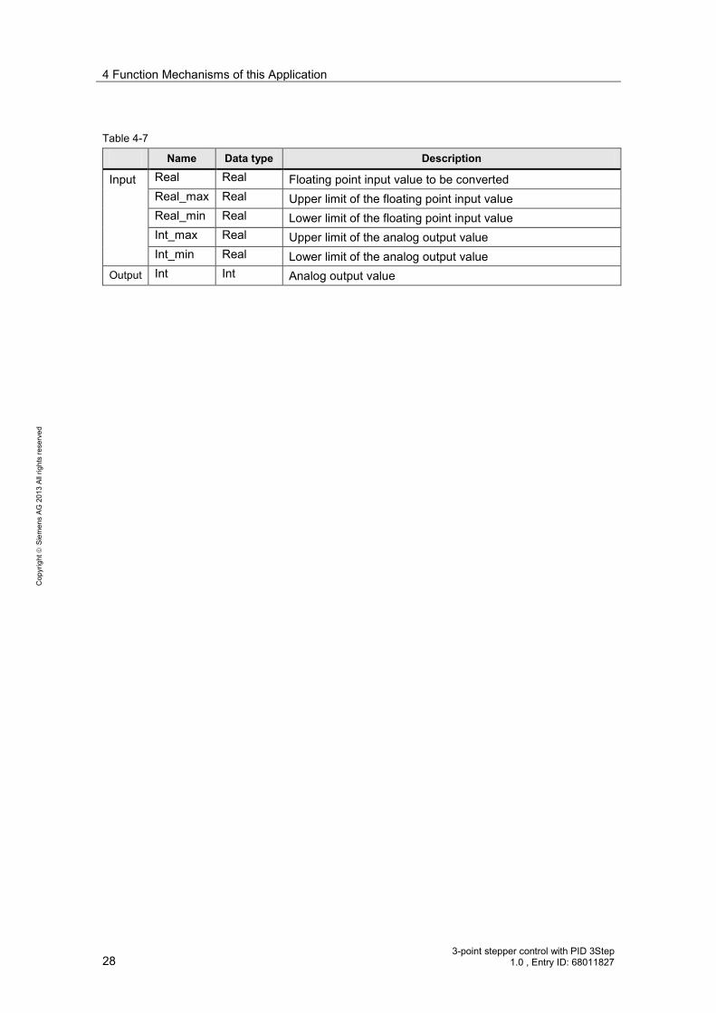
Scale_ Real2Int [FC5] The “Scale_Real2Int” function is used for converting a floating-point number (data type: Real) into an analog value (data type: Int) within predefined boundaries. The specified output limits “Int_max” and “Int_min” are intentionally defined as “Real”, in order to guarantee the compatibility with the specified limits in the instance data block of “PID_3Step”. The conversion of the controlled system output (actual temperature value) into an analog value is necessary to be able to simulate the behavior in the case of an error. For a real controlled system, an error occurs when the actual value sensor fails (e.g. due to wire break). In the simulation this is achieved by overwriting the analog actual value with a value outside the measuring range (-32768) (see Figure 4-4). Figure 4-13 Calling the “Scale_ Real2Int” function
4 Function Mechanisms of this Application
28 3-point stepper control with PID 3Step
1.0 , Entry ID: 68011827
Cop
yrig
ht
Sie
men
s AG
201
3 Al
l rig
hts
rese
rved
Table 4-7
Name Data type Description
Input Real Real Floating point input value to be converted Real_max Real Upper limit of the floating point input value Real_min Real Lower limit of the floating point input value Int_max Real Upper limit of the analog output value Int_min Real Lower limit of the analog output value
Output Int Int Analog output value

5 Startup of the Application
3-point stepper control with PID 3Step 1.0 , Entry ID: 68011827 29
Cop
yrig
ht
Sie
men
s AG
201
3 Al
l rig
hts
rese
rved
5 Startup of the Application 5.1 Hardware adaptation
This application was implemented with a CPU 1516-3 PN/DP. Depending on the design of your selected valve, the hardware configuration of your S7-1500 might need adjustment. The configuration options of S7-1500 for operating the “PID_3Step” 3-point stepper controller are introduced below.
5.1.1 Input signal
The periphery acquires the controlled variable as an analog value. “PID_3Step” offers the conversion of the analog value into the physical unit in the configuration screen. The modules for the analog value acquisition are listed below.
Controlled variable acquisition and valve position feedback Table 5-1
Analog inputs Order number Resolution
AI 8xU/I/RTD/TC ST 6ES7 531-7KF00-0AB0 16 Bit AI 8xU/I/ HS 6ES7 531-7NF10-0AB0 16 Bit
5.1.2 Output signal
“PID_3Step” offers the control of the value via 2 digital outputs (in 2 directions) or via an analog output.
Digital outputs Depending on the power consumption of your digital valve control, you can choose between S7-1500 modules with transistor or relay outputs:
Table 5-2
Digital outputs Order number Current (max.)
Transistor (20.4 to 28.8 V) 6ES7 522-1BL00-0AB0 0.5 A Relay (5 to 250 V) 6ES7 522-5HF00-0AB0 5 A
Analog outputs Table 5-3
Analog inputs Order number Resolution
AI 8xU/I/RTD/TC ST 6ES7 531-7KF00-0AB0 16 Bit AI 8xU/I HS 6ES7 531-7NF10-0AB0 16 Bit
Note Further information on selecting your periphery and its wiring is available in the respective device manuals.

5 Startup of the Application
30 3-point stepper control with PID 3Step
1.0 , Entry ID: 68011827
Cop
yrig
ht
Sie
men
s AG
201
3 Al
l rig
hts
rese
rved
Hardware installation The figure below shows the hardware setup of the application. Figure 5-1 Hardware configuration overview
L1N
DC24V+DC24V-
PE
255.255.255.0Subnet Maske192.168.0.2IP-Adresse
Q0.1 = UpQ0.0 = Down
High Limit = I0.1
Low Limit = I0.0
Process value = AI1
AI2 = Feedback
TP1500 Comfort
CSM 1277 CPU 1211C
Installing hardware Table 5-4
No. Action Comments
1 Adjust the periphery of S7-1500 to the valve you are using. see chapter 5.1 2 Mount all required S7-1500 components on a DIN rail. see chapter 2.3 3 Wire and connect all required components as described in the
respective device manuals.
4 Finally, activate the power supply
5 Startup of the Application
3-point stepper control with PID 3Step 1.0 , Entry ID: 68011827 31
Cop
yrig
ht
Sie
men
s AG
201
3 Al
l rig
hts
rese
rved
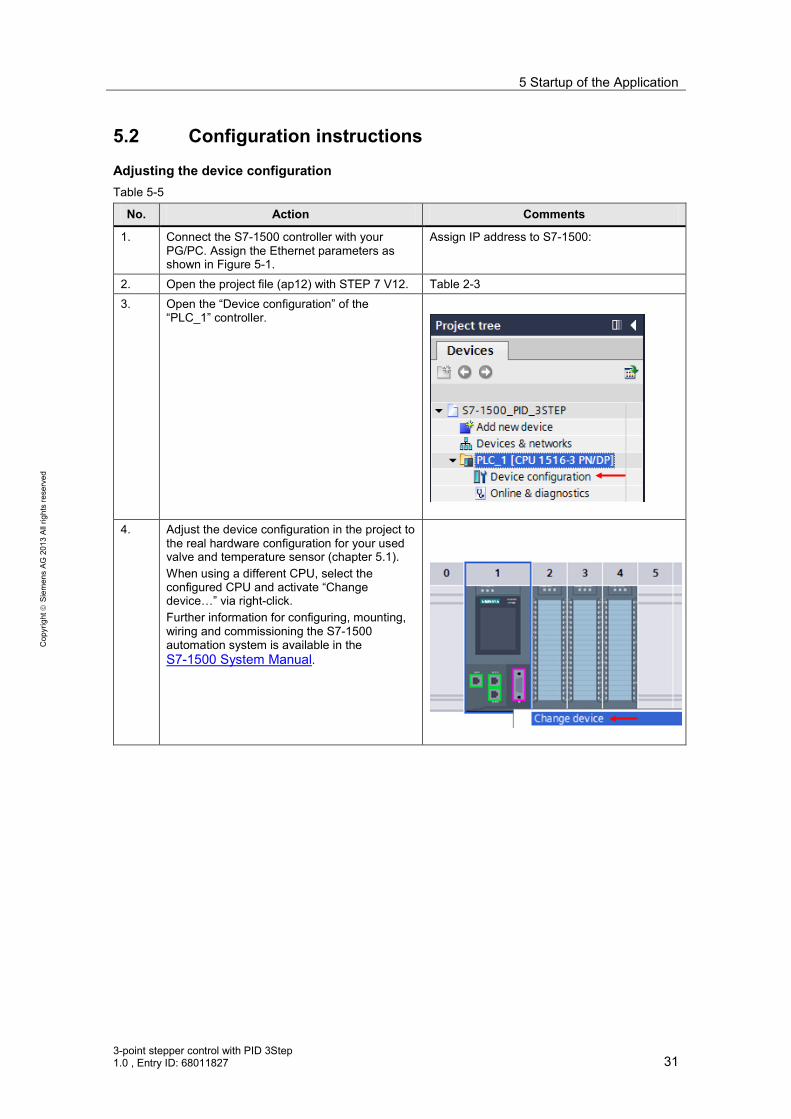
5.2 Configuration instructions
Adjusting the device configuration Table 5-5
No. Action Comments
1. Connect the S7-1500 controller with your PG/PC. Assign the Ethernet parameters as shown in Figure 5-1.
Assign IP address to S7-1500:
2. Open the project file (ap12) with STEP 7 V12. Table 2-3 3. Open the “Device configuration” of the
“PLC_1” controller.
4. Adjust the device configuration in the project to
the real hardware configuration for your used valve and temperature sensor (chapter 5.1). When using a different CPU, select the configured CPU and activate “Change device…” via right-click. Further information for configuring, mounting, wiring and commissioning the S7-1500 automation system is available in the S7-1500 System Manual.

5 Startup of the Application
32 3-point stepper control with PID 3Step
1.0 , Entry ID: 68011827
Cop
yrig
ht
Sie
men
s AG
201
3 Al
l rig
hts
rese
rved
Transferring the I/O addresses Depending on the changed configuration, you transferred the input or output addresses of the added hardware to the program.
This is illustrated at the example of an AI8 x U/I/RTD/TC ST 16 Bit signal board: Table 5-6
No. Action Comments
1. Open the “Device configuration” of the “PLC_1” controller.
2. In the device view of the CPU you select the signal module. Read the input address of the signal module in menu item “I/O addresses”: • “Start address”: 64 • “End address”: 79 The address read via the analog value is “IW64”.

5 Startup of the Application
3-point stepper control with PID 3Step 1.0 , Entry ID: 68011827 33
Cop
yrig
ht
Sie
men
s AG
201
3 Al
l rig
hts
rese
rved
No. Action Comments
3. Open the OB30 “Cyclic interrupt” in the control unit of the project.
4. Since the actual value is read via the signal
board as the temperature, you transfer input word IW64 to the “Input_PER_physical” parameter of the “Switch” function in network 3. Furthermore, you have the option to adjust the • digital input addresses for the end
positions of the valve (Actuator_H_ physical / Actuator_L_ physical)
• analog input address for the feedback signal of the valve position (Feedback_PER_physical)

5 Startup of the Application
34 3-point stepper control with PID 3Step
1.0 , Entry ID: 68011827
Cop
yrig
ht
Sie
men
s AG
201
3 Al
l rig
hts
rese
rved
No. Action Comments
5. If using a valve with analog control you transfer the address of the analog output in network 4. Furthermore, you can also adjust the digital control signals at the I/O: • Output_UP • Output_DN

5 Startup of the Application
3-point stepper control with PID 3Step 1.0 , Entry ID: 68011827 35
Cop
yrig
ht
Sie
men
s AG
201
3 Al
l rig
hts
rese
rved
Configuring the PID controller The configuration of the “PID_3Step” technology object defines the function principle of the 3-point stepper controller. The settings made determine the default values used by the PID controller when restarting after a cold or warm start (e.g. power failure). A more detailed description is available in the TIA Portal V12 online help.
Table 5-7
No. Action Comments
1. Open the configuration editor by selecting “PLC_1 > Technology objects > PID_3Step_1 > Configuration”.
2. Open the “Basic settings”. Here you determine the properties of the valve you are using: • digital or analog control • does the valve provide a feedback of the
valve position • does the valve have digital end position
switches Note: Setting the controller type (here: Temperature) with the unit (here: °C) is only performed for labeling the axis correctly in the Startup wizard.
3. Open the “Process value scaling”:
Here you determine the limits of the process value (Input_PER). Note: please ensure that the correct settings for upper and lower actual value (here: 0 to +100°C), since the controller turns inactive when these limits are violated!

5 Startup of the Application
36 3-point stepper control with PID 3Step
1.0 , Entry ID: 68011827
Cop
yrig
ht
Sie
men
s AG
201
3 Al
l rig
hts
rese
rved
No. Action Comments
4. Open the “Actuator settings”. “Actuator-specific times” If your used valve does not give any position feedback, neither analog nor digital, the “Motor transition time” must be specified here as precisely as possible. For adjusting the actuator inertia you can specify minimal switch ON/OFF times. “Reaction to error” Determine whether the current valve position or a substitute output value as a percentage shall be approached in the case of an error. “Feedback scaling” When using a valve with position feedback (Feedback_PER), you determine the limits here.
5. Open the “Advanced settings”:
“Process value monitoring” Here you can specify warning limits where a respective warning bit will be activated when exceeded or fallen short of. “PID Parameters” If you do not wish to use the self-optimization function, please specify the control parameters manually. These values are written to the instance data block of the “PID_3Step” and adopted as actual values after a cold start (loading project into the controller).
6. Save the project.
Then select the program folder of the S7-1500 and transfer the program to the controller via “Online > Download to device”. Make sure that the LED of the S7-1500 controller indicates the “RUN” status.

5 Startup of the Application
3-point stepper control with PID 3Step 1.0 , Entry ID: 68011827 37
Cop
yrig
ht
Sie
men
s AG
201
3 Al
l rig
hts
rese
rved
Note The CPUs of the S7-1500 series apply changes to DB start values only during the next STOP-RUN transition.
Please consider this behavior when making changes to the data blocks.
5.3 Commissioning the 3-point stepper controller
Configure the 3-point stepper controller in the startup editor for the automatic settings during startup and for the automatic setting during operation. The settings made determine the default values used by the PID controller when restarting after a cold or warm start (e.g. power failure). A more detailed description is available in the TIA Portal V12 online help.
Table 5-8
No. Action Comments
1. Open the Commissioning editor by selecting “PLC_1 > Technology objects > PID_3Step_1 > Commissioning”.
2. Connect the programming device to the CPU by
selecting “PLC_1” and clicking to the “Go online” button.
3. Open the “Transition time” folder in the
Commissioning editor.

5 Startup of the Application
38 3-point stepper control with PID 3Step
1.0 , Entry ID: 68011827
Cop
yrig
ht
Sie
men
s AG
201
3 Al
l rig
hts
rese
rved
No. Action Comments
4. Depending on the “Type of the position feedback” you can measure the transition time of your valve here: • When using the stop signals of the actuator
you can decide whether the “Direction selection” shall be “up-down-up” or “down-up-down”.
• When using the position feedback, you must assign a target position with a distance of at least 50% from the current position feedback.
• Without position feedback, the transition time must be specified as precisely as possible.
Start the transition time measurement.
5. After completion, upload the measured transition time into the project. The measured transition time is written to the instance data block of “PID_3Step” as the start value and restarts with this transition time after a cold or warm start (e.g. power failure).
6. Open the “Tuning” folder in the Commissioning
editor.
7. Start the measurement.
8. Without manual preassignment of the PID parameters (Table 5-7, step 5) the status indicates that tuning has not yet been started, and after the first startup of the CPU the controller is in Disabled (inactive) mode.

5 Startup of the Application
3-point stepper control with PID 3Step 1.0 , Entry ID: 68011827 39
Cop
yrig
ht
Sie
men
s AG
201
3 Al
l rig
hts
rese
rved
No. Action Comments
9. From the inactive state you can only start with “Pretuning”. Selecting “Fine tuning” starts pretuning followed by a fine tuning. Specify a setpoint in central area of the actual value range (e.g. via a monitoring table). Note: The start value of the setpoint value has already been predefined accordingly. Start the pretuning process.
10. After successful pretuning, the controller goes to automatic mode. The determined values can be viewed via “Go to PID parameters”. “Upload PID parameters” writes the determined values as start values into the instance data block of “PID_3Step”.
11. Specify a setpoint in central area of the actual value range (e.g. via a monitoring table). Note: The start value of the setpoint value has already been predefined accordingly. In automatic mode you can now directly start the fine tuning.
12. After the successful fine tuning of the PID parameters, the determined PID parameters can be loaded values into the instance data block of “PID_3Step” as start values.
Note The PID parameters are stored retentively in the instance data block of the “PID_3Step” 3-point stepper controller. During a warm start (restored power) the last processed values remain. The start values are only loaded during cold start (transferring the project in STOP mode).

5 Startup of the Application
40 3-point stepper control with PID 3Step
1.0 , Entry ID: 68011827
Cop
yrig
ht
Sie
men
s AG
201
3 Al
l rig
hts
rese
rved
5.4 HMI project part
Configuring the HMI When using the TP1500 Comfort Panel as operator panel you set the project-specific IP address (see Figure 5-1).
Table 5-9
1. • Select the “Control Panel” button to open the properties of the control panel of the Boot Loader.
2. • Select the “Transfer” button to open the “Transfer Settings” dialog box.
• Activate “Enable Transfer”. • Activate "Remote Control". • Select the “PN/IE” data channel and
adjust its parameters via "Properties...".
3. • Open the "PN_X1" entry. The
“’PN_X1' Settings” dialog box opens. • Select the specific address. • Enter the
– IP address = 192.168.0.04 and the – Subnet Mask= 255.255.255.0 via the screen keyboard.
• Select “OK” to close the dialog box and apply the entries.
5 Startup of the Application
3-point stepper control with PID 3Step 1.0 , Entry ID: 68011827 41
Cop
yrig
ht
Sie
men
s AG
201
3 Al
l rig
hts
rese
rved
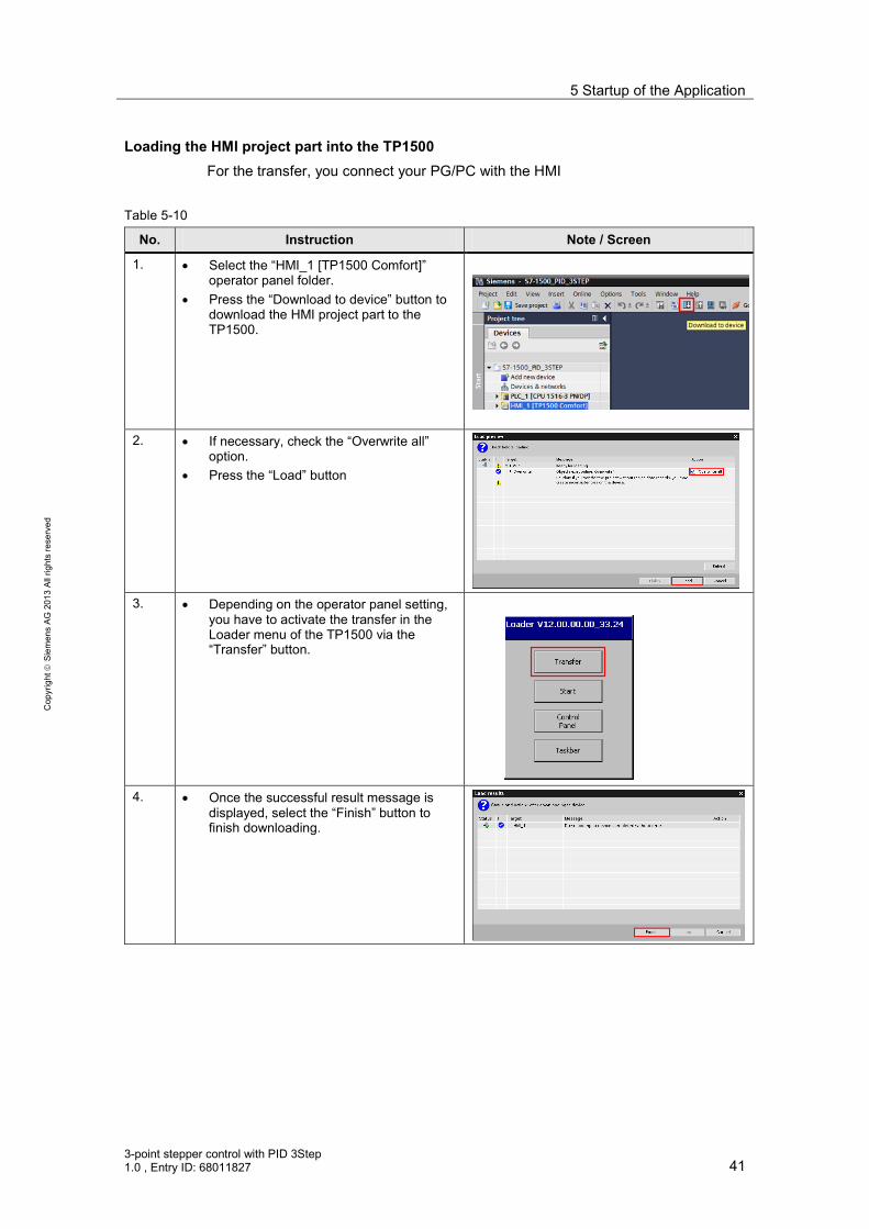
Loading the HMI project part into the TP1500 For the transfer, you connect your PG/PC with the HMI
Table 5-10
No. Instruction Note / Screen
1. • Select the “HMI_1 [TP1500 Comfort]” operator panel folder.
• Press the “Download to device” button to download the HMI project part to the TP1500.
2. • If necessary, check the “Overwrite all”
option. • Press the “Load” button
3. • Depending on the operator panel setting,
you have to activate the transfer in the Loader menu of the TP1500 via the “Transfer” button.
4. • Once the successful result message is
displayed, select the “Finish” button to finish downloading.

5 Startup of the Application
42 3-point stepper control with PID 3Step
1.0 , Entry ID: 68011827
Cop
yrig
ht
Sie
men
s AG
201
3 Al
l rig
hts
rese
rved
Starting PC runtime If the PG/PC is to be used as operator panel, start the PC runtime as follows:
Table 5-11
No. Instruction Note / Screen
1. • Select the “HMI_1 [TP1500 Comfort]” operator panel folder.
• Click the “Start simulation” button.

6 Operating the Application
3-point stepper control with PID 3Step 1.0 , Entry ID: 68011827 43
Cop
yrig
ht
Sie
men
s AG
201
3 Al
l rig
hts
rese
rved
6 Operating the Application Overview
Figure 6-1 Overview - Operating the application
Mixer tap Trend view Tuning
Monitoring Configuration Simulation
StartscreenOverview Support
Operating System-functions
Overview
The user interface consists of 12 screens: • Start screen (Welcome) • Support (Information on the Siemens Industry Online Support) • Overview of application-specific screens:
– Mixer tap – Trend view – Tuning – Monitoring – Configuration – Simulation
• Operation (explanation of the symbol) • System functions of the HMI panel

6 Operating the Application
44 3-point stepper control with PID 3Step
1.0 , Entry ID: 68011827
Cop
yrig
ht
Sie
men
s AG
201
3 Al
l rig
hts
rese
rved
6.1 Overview of the application-specific screens Figure 6-2 Overview of the application-specific screens
StartscreenOverview Support
Operating System-functions
Overview
6.1.1 Start screen
Figure 6-3 Start screen
From the start screen, you get to the: • overview via the “PID_3Step (S7-1500)” button • support information via the “Support” button.
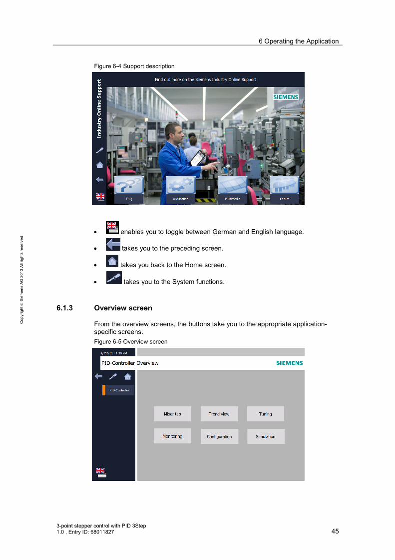
6.1.2 Support description
This support description gives information on the Siemens Industry Online Support.
6 Operating the Application
3-point stepper control with PID 3Step 1.0 , Entry ID: 68011827 45
Cop
yrig
ht
Sie
men
s AG
201
3 Al
l rig
hts
rese
rved
Figure 6-4 Support description
• enables you to toggle between German and English language.
• takes you to the preceding screen.
• takes you back to the Home screen.
• takes you to the System functions.
6.1.3 Overview screen
From the overview screens, the buttons take you to the appropriate application-specific screens. Figure 6-5 Overview screen

6 Operating the Application
46 3-point stepper control with PID 3Step
1.0 , Entry ID: 68011827
Cop
yrig
ht
Sie
men
s AG
201
3 Al
l rig
hts
rese
rved
Figure 6-6 Overview screen
• The header contains the date, the screen title and the local time.
• takes you to the explanation of symbols in the footer.
6.1.4 Operating screen
The Operating screen explains the task of the individual symbols in the footer. Figure 6-7 Operating screen
• takes you to the Home screen (Figure 6-3).
• takes you to the Overview screen (Figure 6-6).
• takes you to the Operating screen (this screen).

6 Operating the Application
3-point stepper control with PID 3Step 1.0 , Entry ID: 68011827 47
Cop
yrig
ht
Sie
men
s AG
201
3 Al
l rig
hts
rese
rved
• takes you to the preceding screen in the order of the application-specific screens (Overview, Mixer tap, Trend view, Tuning, Monitoring, Configuration and Simulation).
• takes you to the last screen called up.
• takes you to the next screen in the list:
• takes you to the System functions (Figure 6-8).
• enables you to toggle between German and English language.
6.1.5 System functions
Figure 6-8 System functions screen
The HMI system function enables you to: • switch on the screen keyboard • call up the Windows Task Manager • calibrate the touch panel • go online and offline • terminate Runtime • go to the transfer mode (where you can make settings in the control panel)
6 Operating the Application
48 3-point stepper control with PID 3Step
1.0 , Entry ID: 68011827
Cop
yrig
ht
Sie
men
s AG
201
3 Al
l rig
hts
rese
rved
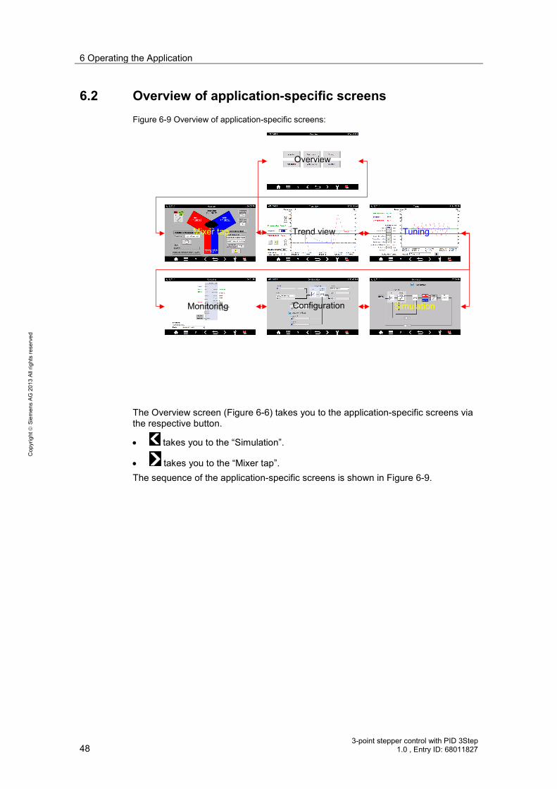
6.2 Overview of application-specific screens Figure 6-9 Overview of application-specific screens:
Mixer tap Trend view Tuning
Monitoring Configuration Simulation
Overview
The Overview screen (Figure 6-6) takes you to the application-specific screens via the respective button.
• takes you to the “Simulation”.
• takes you to the “Mixer tap”. The sequence of the application-specific screens is shown in Figure 6-9.
6 Operating the Application
3-point stepper control with PID 3Step 1.0 , Entry ID: 68011827 49
Cop
yrig
ht
Sie
men
s AG
201
3 Al
l rig
hts
rese
rved
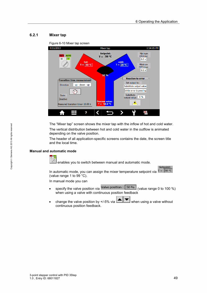
6.2.1 Mixer tap
Figure 6-10 Mixer tap screen
The “Mixer tap” screen shows the mixer tap with the inflow of hot and cold water. The vertical distribution between hot and cold water in the outflow is animated depending on the valve position. The header of all application-specific screens contains the date, the screen title and the local time.
Manual and automatic mode
enables you to switch between manual and automatic mode.
In automatic mode, you can assign the mixer temperature setpoint via (value range 1 to 99 °C). In manual mode you can
• specify the valve position via (value range 0 to 100 %) when using a valve with continuous position feedback
• change the valve position by +/-5% via when using a valve without continuous position feedback.

6 Operating the Application
50 3-point stepper control with PID 3Step
1.0 , Entry ID: 68011827
Cop
yrig
ht
Sie
men
s AG
201
3 Al
l rig
hts
rese
rved
Transition time Depending on the type of the position feedback you can measure the transition time of your valve in automatic mode: • When using the stop signals of the actuator you can choose between the
direction or . • When using the continuous position feedback, the application sets the target
position to
– at current valve position >= 50%
– at current valve position <50% • Without position feedback (stop signals or continuous position feedback), the
transition time must be specified as precisely as possible via
.
With position feedback you start the transition time measurement via .
The following status is displayed: After successful measurement, the measured transition time is displayed:
NOTICE In order to start up with the measured transition time after a power failure, this value must be written to the instance data block of “PID_3Step” as a start value. The commissioning wizard offers this function (Table 5-8 , Step 5).
Actuator switching times For adjustment to possible actuator inertia you can vary
• the (“minimal switch-on time”) and
• the (“minimal switch-off time”).
NOTICE In order to start up with these settings after a power failure, this value must be written to the instance data block of “PID_3Step” as a start value. The configuration wizard offers this function (Table 5-7, Step 4) at the subsequent transmission of the instance data block.

6 Operating the Application
3-point stepper control with PID 3Step 1.0 , Entry ID: 68011827 51
Cop
yrig
ht
Sie
men
s AG
201
3 Al
l rig
hts
rese
rved
Reaction to error Determine whether in case of an error
• the current valve position or
• a substitute output value must be specified via
(value range 0 to 100 %)
– for the duration of the error or
– permanently shall be controlled.
NOTICE In order to save this presetting through a power failure, this value must be written to the instance data block of “PID_3Step” as a start value. The configuration wizard offers this function (Table 5-7, Step 4) at the subsequent transmission of the instance data block.
Controlled system simulation In controlled system simulation • in automatic mode, the behavior can be simulated in the case of an error via
(switching on and off)
• the hot water temperature via in the range between 70 to 90 °C.
• the cold water temperature via in the range between 10 to 30 °C can be varied for disturbance variable control.

6 Operating the Application
52 3-point stepper control with PID 3Step
1.0 , Entry ID: 68011827
Cop
yrig
ht
Sie
men
s AG
201
3 Al
l rig
hts
rese
rved
6.2.2 Trend view
Figure 6-11 Trend view screen
The “Trend view” screen shows the time sequence over 90 seconds.
• the mixing temperature (scale center)
• the actual mixing temperature value (scale left)
• the valve position (scale right)
Manual and automatic mode
enables you to switch between manual and automatic mode. In automatic mode, you can assign the mixer temperature setpoint via
(value range 1 to 99 °C). In manual mode you can
• specify the valve position via (value range 0 to 100 %) when using a valve with continuous position feedback
• change the valve position by +/-5% via when using a valve without continuous position feedback.
Dead band width The dead band suppresses the noise fraction in the steady controller state. Specify
the size of the deadband via . At a deadband width of 0.0 the dead band is switched off. The smaller the deadband width you choose, the more exactly the attempt of the controller to adjust the controller to the actual value is. This higher precision, however, often leads to a more frequent control of the valve.

6 Operating the Application
3-point stepper control with PID 3Step 1.0 , Entry ID: 68011827 53
Cop
yrig
ht
Sie
men
s AG
201
3 Al
l rig
hts
rese
rved
Reaction to error If by default the valve approaches the substitute output value in the case of an error, you specify that value via "Substitute valve position"
.
Controlled system simulation In controlled system simulation operation, the behavior can be simulated in
automatic mode in the case of an error via (switching on and off) The dashed lines represent the inflow temperatures: • the upper one for hot water (range between 70 to 90 °C) and • the bottom one for cold water (range between 10 to 30 °C). In controlled system simulation mode, the respective inflow temperature can be varied
• by +10°C via and
• by -10°C via can be varied for disturbance variable control. When specifying the setpoint above the hot or below the cold water temperature, the simulated actual temperature value is limited by this.
6.2.3 Tuning
Figure 6-12 Tuning screen
The Tuning screen provides the following options • for pretuning from the inactive controller state or • fine tuning from the automatic mode. For pretuning you can chose between the following tuning methods: • Chien, Hrones, Reswick PID • Chien, Hrones, Reswick PI

6 Operating the Application
54 3-point stepper control with PID 3Step
1.0 , Entry ID: 68011827
Cop
yrig
ht
Sie
men
s AG
201
3 Al
l rig
hts
rese
rved
For fine tuning you can chose between the following tuning methods: • PID automatic • PID fast • PID slow • Ziegler-Nichols PID • Ziegler-Nichols PI • Ziegler-Nichols P
Pressing starts the selected tuning method.
Note Enter a setpoint value as close to the central field of the actual value range to avoid cancelling the tuning by reaching the limit.
During tuning, the setpoint is frozen, the tuning status and the percentage progress is displayed. After successful tuning, the determined controller parameters are displayed in the “CtrlParams” column and the controller parameters prior to tuning are moved to the “BackUp” column. The secured “BackUp” parameter set can be loaded back into the controller with
. The current controller parameters (“CtrlParams”) can also be edited manually.
Note The current controller parameter set (“CtrlParams”) is retentive and is also loaded again after power failure. In order to use these parameters for starting after a cold start, they must be written as into the instance DP of “PID_3Step” as a start value. The commissioning wizard offers this function (Table 5-8 , Step 10).
6 Operating the Application
3-point stepper control with PID 3Step 1.0 , Entry ID: 68011827 55
Cop
yrig
ht
Sie
men
s AG
201
3 Al
l rig
hts
rese
rved
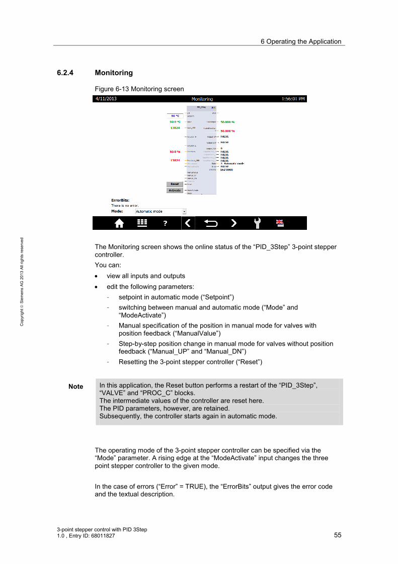
6.2.4 Monitoring
Figure 6-13 Monitoring screen
The Monitoring screen shows the online status of the “PID_3Step” 3-point stepper controller. You can: • view all inputs and outputs • edit the following parameters:
– setpoint in automatic mode (“Setpoint”) – switching between manual and automatic mode (“Mode” and
“ModeActivate”) – Manual specification of the position in manual mode for valves with
position feedback (“ManualValue”) – Step-by-step position change in manual mode for valves without position
feedback (“Manual_UP” and “Manual_DN”) – Resetting the 3-point stepper controller (“Reset”)
Note In this application, the Reset button performs a restart of the “PID_3Step”, “VALVE” and “PROC_C” blocks. The intermediate values of the controller are reset here. The PID parameters, however, are retained. Subsequently, the controller starts again in automatic mode.
The operating mode of the 3-point stepper controller can be specified via the “Mode” parameter. A rising edge at the “ModeActivate” input changes the three point stepper controller to the given mode. In the case of errors (“Error” = TRUE), the “ErrorBits” output gives the error code and the textual description.

6 Operating the Application
56 3-point stepper control with PID 3Step
1.0 , Entry ID: 68011827
Cop
yrig
ht
Sie
men
s AG
201
3 Al
l rig
hts
rese
rved
The occurring error messages are also displayed globally.
Errors must be acknowledged via .
Note A detailed description of the error messages (ErrorBits) is available in the STEP 7 V12 online help.
6.2.5 Configuration
Figure 6-14 Configuration screen
The Configuration screen matches the basic settings of the configuration wizard (Table 5-7, Step 2). Here, you can change the following specifications during runtime: • Actual value input: floating-point number (“Input”) or analog (“Input_PER”) • Position feedback of the valve:
– no feedback (standard) – feedback signal via floating-point number (“Feedback”) – analog feedback signal (“Feedback_PER”)
• Valve provides end stop signals or not • Manipulated variable output: via 2 direction control (“Output (digital)”) or analog
(“Output_PER”) This screen familiarizes with the settings of the 3-point stepper controller and its characteristics (especially for the simulation mode).

6 Operating the Application
3-point stepper control with PID 3Step 1.0 , Entry ID: 68011827 57
Cop
yrig
ht
Sie
men
s AG
201
3 Al
l rig
hts
rese
rved
NOTICE In order to save this configuration through a power failure, these values must be written to the instance data block of “PID_3Step” as a start value. The configuration wizard offers this function (Table 5-7, Step 2) at the subsequent transmission of the instance data block.
6.2.6 Simulation
Figure 6-15 Simulation screen
The Simulation screen enables switching between a real and a simulated control system. The block diagram of the “PID_3Step” 3-point stepper controller is displayed with: • the setpoint specification • the actual value • the valve feedback:
– position feedback – end stop signal “closed” – end stop signal “open”
• the digital valve control signals – Open – Close.
If the simulation is not switched on, the controller receives the signals from the controller I/O (Table 5-6, Step 4).
When the simulation is switched on, the screen shows the block diagram structure as the input signals for the controller are calculated:
The digital valve control signals feed a valve simulation , which supplies the valve feedback.

7 Internet Links
58 3-point stepper control with PID 3Step
1.0 , Entry ID: 68011827
Cop
yrig
ht
Sie
men
s AG
201
3 Al
l rig
hts
rese
rved
The percentage value of the valve position feedback is limited by the hot
and cold water temperature and supplies the setpoint temperature value for the controlled system.
The output of the controlled system simulation block PT1 supplies the actual temperature value.
7 Internet Links This table contains a selection of links on further information. Table 7-1
Topic Title
\1\ SIMATIC S7-1500 Automation System Manual
http://support.automation.siemens.com/WW/view/en/59191792
\2\ Signal Modules Manual http://support.automation.siemens.com/WW/view/en/57251228/133300
\3\ STEP 7 Basic V12.0 System Manual
http://support.automation.siemens.com/WW/view/en/68113678
\4\ This entry http://support.automation.siemens.com/WW/view/en/68011827
8 History Table 8-1
Version Date Modifications
V1.0 04/2013 First version