3. design of structures, components, ap1000 european equipment and … · 2015-06-16 · design of...
TRANSCRIPT

3. Design of Structures, Components, AP1000 European Equipment and Systems Design Control Document
EPS-GW-GL-700 3D-1 Revision 1
APPENDIX 3D
METHODOLOGY FOR QUALIFYING AP1000 SAFETY-RELATED ELECTRICAL AND MECHANICAL EQUIPMENT
Safety-related electrical equipment is tested under the environmental conditions expected to occur in the event of a design basis event. This testing provides a high degree of confidence in the safety-related system performance under the limiting environmental conditions. Qualification criteria were revised by IEEE 323-1974 (Reference 1) and by Regulatory Guide 1.89, which endorses this IEEE standard. The concept of aging was highlighted in IEEE 323-1974, and interpretation of the scope of aging and implementation methods were subsequently developed. 10 CFR 50.49 provides the NRC requirements for qualification of equipment located in potentially harsh environments. Therefore, the guidance provided by IEEE 323-1974 is the evolutionary root of requirements, recommended methods, and qualification procedures described in this appendix.
Specific treatment of seismic qualification, part of the qualification test sequence recommended in IEEE 323-1974, is addressed in IEEE 344-1987 (Reference 2). This appendix bases technical guidance, recommendations, and requirements for seismic qualification on IEEE 344-1987.
The AP1000 Equipment Qualification methodology addresses the expanded scope of IEEE 627-1980 (Reference 3), which encompasses the qualification of Class 1E electrical and safety-related mechanical equipment. IEEE 627 generalizes the principles and technical guidance of IEEE 323 and 344. Compliance with the IEEE 323-1974 and 344-1987 is the specific means of compliance with the intent of IEEE 627-1980 for safety-related electrical and mechanical equipment.
Safety-related electrical and mechanical equipment is typically qualified using analysis, testing, or a combination of these methods. The specific method or methods used depend on the safety-related function of the equipment type to be qualified. Safety-related mechanical equipment, such as tanks and valves, is typically qualified by analysis, with supplementary functional testing when functional operability is demonstrated only through testing, as is the case for active valves. Either testing or testing combined with analysis is the method used for environmental and seismic qualification of safety-related (Class 1E) electrical equipment.
The technical discussions of this appendix follow the format headings of the equipment qualification data packages (EQDPs) to be issued as specific qualification program documentation. This formatting (see Section 3D.7) permits easy cross-reference between the methodology defined in this report and the detailed plans contained in the equipment qualification data packages. Attachment A of this appendix is the format used for the equipment qualification data package.
Attachment B of this appendix, "Aging Evaluation Program," describes methods for addressing potential age-related, common-mode failure mechanisms used in AP1000 equipment qualification programs. The approach conforms with current industry positions and makes maximum use of available data and experience in the evaluation, test, and analysis of aging mechanisms.

3. Design of Structures, Components, AP1000 European Equipment and Systems Design Control Document
EPS-GW-GL-700 3D-2 Revision 1
Attachment C, "Effects of Gamma Radiation Doses Below 104 rads (100 Gy) on the Mechanical Properties of Materials," provides the basis that radiation aging below 104 rads (100 Gy) is not a significant factor in the ability of the equipment to perform properly during a seismic event. For some devices, electrical properties are degraded above 103 rads (10 Gy). Radiation aging for safety-related equipment which is subject to lifetime doses of less than 104 rads (103 rads for certain electrical components) and not subject to a high-energy line break environment is not required to be addressed in AP1000 qualification programs.
Attachment D, "Accelerated Thermal Aging Parameters," describes the methodology employed in calculating the accelerated thermal aging parameters used in this program.
Attachment E, "Seismic Qualification Techniques," discusses available methods for establishing a seismic qualification basis, by either test or analysis, and its application to the qualification of safety-related equipment for the AP1000.
3D.1 Purpose
The basic objectives of qualification of safety-related electrical and mechanical equipment follow:
• To reduce the potential for common cause failures due to specified environmental and seismic events
• To demonstrate that safety-related electrical and mechanical equipment is capable of performing its designated safety-related functions.
This appendix describes the methodology that has been adopted to qualify equipment according to IEEE 627-1980, "IEEE Standard for Design Qualification of Safety System Equipment Used in Nuclear Power Generating Stations." The two standards primarily used to demonstrate compliance with this standard are IEEE 323-1974, "IEEE Standard for Qualifying Class 1E Equipment for Nuclear Power Generating Stations," and IEEE 344-1987, "IEEE Recommended Practice for Seismic Qualification of Class 1E Equipment for Nuclear Power Generating Stations."
3D.2 Scope
The qualification criteria, methods, and environmental conditions described constitute the methodology that is adopted to comply with the standards for the AP1000. This methodology applies to safety-related, seismic Category I electrical and mechanical equipment and is also used for certain monitoring equipment. Seismic Category II equipment is also within the scope of this program. The criteria used for the design of seismic Category II structures, systems, and components are discussed in Section 3.7. Performance during abnormal environmental conditions, while not specifically designated as an industry or a regulatory qualification requirement, is also addressed by this appendix. Performance during normal service conditions is demonstrated by tests and inspections addressed by the equipment specification. Electromagnetic interference (EMI) testing or analysis is not included in the qualification process and is addressed on an individual equipment basis, as necessary.
3. Design of Structures, Components, AP1000 European Equipment and Systems Design Control Document
EPS-GW-GL-700 3D-3 Revision 1
3D.3 Introduction
This appendix identifies qualification methods used for the AP1000 to demonstrate the performance of safety-related electrical and mechanical equipment when subjected to abnormal and accident environmental conditions including loss of ventilation systems, feedline, steamline and main coolant system breaks, and seismic events. This appendix provides the expected conditions for various locations in the AP1000. General requirements for the development of plans/procedures/reports are also provided. Section 3D.4 identifies the various industry and regulatory criteria upon which the program is based. Section 3D.5 defines the design specifications and applicable test environments. Section 3D.6 defines the basis for the qualification method selection. Section 3D.7 outlines the documentation requirements.
3D.4 Qualification Criteria
The environmental requirements considered in the design of safety-related equipment are embodied in GDC 2, "Design Bases for Protection Against Natural Phenomena"; GDC 4, "Environmental and Missile Design Bases"; and GDC 23, "Protection System Failure Modes." GDC 1, "Quality Standards and Records," and Criterion III, "Design Control," Criterion XI, "Test Control," and Criterion XVII, "Quality Assurance Record" of 10 CFR Part 50, Appendix B, "Quality Assurance Criteria for Nuclear Power Plants and Fuel Reprocessing Plants," to require that the environmental design of safety-related equipment is verified, documented, and controlled.
The qualification methods described in this appendix are used to verify the environmental design basis and capability of the safety-related electrical and mechanical equipment supplied for the AP1000. The results of the verification, as well as the design basis for each equipment, is documented in an equipment qualification data package. (See Attachment A for sample format.) Design control, test control, and quality assurance record keeping is performed through the AP1000 Quality Assurance Program. (See Chapter 17.)
3D.4.1 Qualification Guides
IEEE 323-1974 and 344-1987 serve as the basis upon which the AP1000 equipment qualification methodology demonstrates compliance with IEEE 627-1980. NRC regulations stated in 10 CFR 50.49, "Environmental Qualification of Electrical Equipment Important to Safety for Nuclear Power Plants," and NRC guidance provided in Regulatory Guide 1.89, and Regulatory Guide 1.100, endorse IEEE 323-1974 and IEEE 344-1987, respectively. The intent of the more general IEEE 627-1980 is addressed through conformance with IEEE 323 and 344.
3D.4.1.1 IEEE Standards
The following lists additional standards and guides used in developing the methodology:
• IEEE 98-1984, "IEEE Standard for the Preparation of Test Procedures for the Thermal Evaluation of Solid Electrical Insulating Materials"
• IEEE 100-1996, "IEEE Standard Dictionary of Electrical and Electronic Terms"

3. Design of Structures, Components, AP1000 European Equipment and Systems Design Control Document
EPS-GW-GL-700 3D-4 Revision 1
• IEEE 308-1991, "IEEE Standard Criteria for Class 1E Power System for Nuclear Power Generating Stations"
• IEEE 317-1983, "IEEE Standard for Electric Penetration Assemblies in Containment Structure for Nuclear Power Generating Stations"
• IEEE 381-1977, "IEEE Standard Criteria for Type Tests of Class 1E Modules Used in Nuclear Power Generating Stations"
• IEEE 382-1996, "IEEE Standard for Qualification of Actuators for Power-Operated Valve Assemblies with Safety-Related Functions for Nuclear Power Generating Stations"
• IEEE 383-1974, "IEEE Standard for Type Test of Class 1E Electric Cables, Field Splices, and Connections for Nuclear Power Generating Stations"
• IEEE 420-1982, "IEEE Standard Design and Qualification of Class 1E Control Boards, Panels, and Racks Used in Nuclear Powered Generating Stations"
• IEEE 494-1974, "IEEE Standard Method for Identification of Documents Related to Class 1E Equipment and Systems for Nuclear Power Generating Stations"
• IEEE 535-1986, "IEEE Standard for Qualifying Class 1E Lead Storage Batteries for Nuclear Power Generating Stations"
• IEEE 572-1985, "IEEE Standard for Qualification of Class 1E Connection Assemblies for Nuclear Power Generating Stations"
• IEEE 603-1991, "IEEE Standard Criteria for Safety Systems for Nuclear Power Generating Stations"
• IEEE 649-1991, "IEEE Standard for Qualifying Class 1E Motor Control Centers for Nuclear Power Generating Stations"
• IEEE 650-1990, "IEEE Standard for Qualification of Class 1E Static Battery Chargers and Inverters for Nuclear Power Generating Stations"
• IEEE-741-1997, "IEEE Standard Criteria for the Protection of Class 1E Power Systems and Equipment in Nuclear Power Generating Stations"
• ANSI/IEEE C37.98-1987, "IEEE Standard for Seismic Testing of Relays".
3D.4.1.2 NRC Regulatory Guides
In the area of seismic and environmental qualification of safety-related electrical and mechanical equipment, the NRC has issued the following Regulatory Guides:
Regulatory Guide 1.33, "Quality Assurance Program Requirements (Operation)" – The guide endorses ANS and ANSI standards for quality assurance programs, but is considered here

3. Design of Structures, Components, AP1000 European Equipment and Systems Design Control Document
EPS-GW-GL-700 3D-5 Revision 1
specifically for guidance in determining documentation adequacy. Appendix A of the guide, Item 9, "Procedures for Performing Maintenance," addresses procedural and documentation requirements for maintenance of safety-related equipment, preventive maintenance, repair, and replacement. This guide is a source in the development of qualification in the on-going qualification programs discussed in subsection 3D.6.4.
Regulatory Guide 1.61, "Damping Values for Seismic Design of Nuclear Plants" – The guide prescribes acceptable values of damping used in elastic modal dynamic seismic analysis of seismic Category I structures, systems, and components. The AP1000 equipment qualification program is based on Regulatory Guide 1.61 and on values considered to be acceptable based on past NRC acceptances. The safe shutdown earthquake (SSE) damping values used for the qualification of mechanical and electrical equipment are listed in Table 3.7.1-1 of Chapter 3.
Regulatory Guide 1.63, "Electric Penetration Assemblies in Containment Structures for Nuclear Power Plants" – The guide endorses, with certain qualifications, IEEE 317-1983. External circuit protection of electric penetration assemblies should meet the provisions of Section 5.4 of IEEE 741-1986, "Criteria for Protection of Class 1E Power Systems and Equipment in Nuclear Generating Stations, as these are beyond the scope of IEEE 317. The AP1000 design complies with IEEE 741-1997. The AP1000 equipment qualification program employs the recommendations of Regulatory Guide 1.63, Revision 3, in specifying qualification plans as a means of supplementing the guidance of IEEE 317 and 323.
Regulatory Guide 1.73, "Qualification Tests of Electric Valve Operators Installed Inside the Containment of Nuclear Power Plants" – The guide endorses, with certain qualifications, IEEE 382-1972. The AP1000 equipment qualification program employs recommendations of Regulatory Guide 1.73, but gives preference to the guidance of IEEE 382-1996, where it is necessary to supplement the guidance of IEEE 323 or 344 in specifying qualification plans for electric valve operators.
Regulatory Guide 1.89, "Qualification of Class 1E Equipment for Nuclear Power Plants" – The guide provides guidance for conformance with 10 CFR 50.49, and endorses the procedures of IEEE 323-1974 as an acceptable means for qualifying Class 1E equipment. Implicit in the endorsement of IEEE 323 is the reference to seismic qualification methods of IEEE 344 as a part of the qualification test sequence. (See Regulatory Guide 1.100 later in this discussion.) The AP1000 equipment qualification methodology addresses the recommendations of Regulatory Guide 1.89 by the following:
• The recommendations of IEEE 323-1974 are met by the methods discussed in this appendix.
• The radiation source terms used in qualification differ from those of Regulatory Guide 1.89, and are described in Section 3D.5 of this appendix.
• The seismic qualification requirements employ the recommendations of IEEE 344-1987 as described in Attachment E of this appendix.

3. Design of Structures, Components, AP1000 European Equipment and Systems Design Control Document
EPS-GW-GL-700 3D-6 Revision 1
Regulatory Guide 1.92, "Combining Modal Responses and Spatial Components in Seismic Response Analysis" – The guide describes methods and procedures for the following:
• Combining the values of the response of individual modes in a response spectrum modal dynamic analysis to find the representative maximum value of a particular response of interest for each of the three orthogonal seismic spatial components.
• Combining the maximum values (or representative maximum values) of the responses for a given element of a system or item of equipment, determined for each of the three orthogonal spatial components.
The AP1000 equipment qualification program employs methods consistent with the recommendations of Regulatory Guide 1.92 when combining individual modal response values or the response of three independent spatial components in seismic analyses.
Regulatory Guide 1.97, Revision 3, “Instrumentation for Light-Water-Cooled Nuclear Power Plants to Access Plant and Environs Conditions During and Following an Accident.” The guide describes a method acceptable to provide instrumentation to monitor plant variables and systems during and following an accident in a light-water-cooled nuclear power plant. The AP1000 program, identified as the post-accident monitoring instrumentation system (PAMS), provides the capability to monitor plant variables and systems operating status during and following an accident. PAMS includes those instruments provided to indicate system operating status and furnish information regarding the release of radioactive materials.
Regulatory Guide 1.100, "Seismic Qualification of Electrical Equipment for Nuclear Power Plants" – The guide endorses IEEE 344-1987. Regulatory Guide 1.100 particularly notes that IEEE 344-1987 is applied in the qualification of safety-related mechanical equipment, as well as Class 1E electrical equipment. The AP1000 equipment qualification methodology employs the recommendations of Regulatory Guide 1.100, as described in Attachment E of this appendix.
Regulatory Guide 1.122, "Development of Floor Design Response Spectra for Seismic Design of Floor-Supported Equipment or Components" – The guide describes specific methods for developing floor (and other equipment mounting locations) response spectra. Included are specific criteria for the broadening frequency amplitude peaks and smoothing of the frequency amplitude spectrum to incorporate conservatism in the seismic requirements. This is to compensate for other uncertainties of analysis. The AP1000 equipment qualification program employs methods consistent with the recommendations of Regulatory Guide 1.122.
Regulatory Guide 1.131, "Qualification Tests of Electrical Cables, Field Splices, and Connections for Light-Water Cooled Nuclear Power Plants" – The guide endorses IEEE 383-1974. The AP1000 equipment qualification program employs the recommendations of Regulatory Guide 1.131 in specifying the qualification program plans where this guide supplements the guidance of IEEE 383 and to further demonstrate conformance with the guidance of IEEE 323. As neither IEEE 383 nor Regulatory Guide 1.131 specifically addresses considerations for cable field splices and connections, guidance for their qualification is taken from IEEE 572 and Regulatory Guide 1.156.

3. Design of Structures, Components, AP1000 European Equipment and Systems Design Control Document
EPS-GW-GL-700 3D-7 Revision 1
Regulatory Guide 1.156, "Environmental Qualification of Connection Assemblies for Nuclear Power Plants" – The guide endorses IEEE 572-1985. The AP1000 equipment qualification program employs the recommendations of Regulatory Guide 1.156 in specifying the qualification program plans where this guide supplements the guidance of IEEE 572 to demonstrate conformance with the guidance of IEEE 323.
Regulatory Guide 1.158, "Qualification of Safety-Related Lead Storage Batteries for Nuclear Power Plants" – The guide endorses IEEE 535-1986. The AP1000 equipment qualification program employs the recommendations of Regulatory Guide 1.158 in specifying the qualification program plans where this guide supplements the guidance of IEEE 535 to demonstrate conformance with the guidance of IEEE 323.
Regulatory Guide 1.180, “Guidelines for Evaluating Electromagnetic and Radio-Frequency Interference in Safety-Related Instrumentation and Control Systems.” Regulatory Guide 1.180 provides guidance to evaluate electromagnetic and radio-frequency interference in safety-related instrumentation and control systems. The AP1000 equipment qualification program employs methods consistent with the recommendations of Regulatory Guide 1.180, where applicable.
Regulatory Guide 1.183, “Alternate Radiological Source Terms for Evaluating Design Basis Accidents at Nuclear Power Reactor.” The radiation dose rates and integrated doses applicable for AP1000 following a design basis accident are determined based on the criteria of NUREG-1465 and this regulatory guide.
3D.4.2 Definitions
Definitions of terms used in this appendix are contained in the referenced standards and IEEE 100, "The Authoritative Dictionary of IEEE Standard Terms, Seventh Edition." Subsection 3D.4.5 clarifies the definitions of "life" (that is, design, shelf, and qualified life) as used in this methodology. The terms "design life" and "qualified life" have the meanings set forth in IEEE 323 and are used in the context of that standard.
3D.4.3 Mild Versus Harsh Environments
Qualification requirements differ for equipment located in mild and harsh environments.
IEEE 323 defines a mild environment as an environment expected as a result of normal service conditions and the extremes of abnormal service conditions where a safe shutdown earthquake is the only design basis event of consequence or conditions where thresholds of material degradation are reached. The following limits are established as the delimiting environmental parameter values for mild and harsh environments.
Typically a mild environment conforms with the environmental parameter limits of Table 3D.4-1, though others may apply to specific equipment applications or locations.
The scope of 10 CFR 50.49 is limited exclusively to equipment located in a harsh environment. The AP1000 equipment qualification program conforms with the requirements of 10 CFR 50.49 for the qualification of harsh environment equipment. The "radiation-harsh" environment is a significant subset of the harsh environment category. A radiation-harsh environment is defined for

3. Design of Structures, Components, AP1000 European Equipment and Systems Design Control Document
EPS-GW-GL-700 3D-8 Revision 1
equipment designed to operate above certain radiation thresholds where other environmental parameters remain bounded by normal or abnormal conditions. Any equipment that is above 104 rads (100 Gy) gamma (103, 10 Gy for electronics) will be evaluated to determine if a sequential test which includes aging, radiation, and the applicable seismic event is required or if sufficient documentation exists to preclude such a test.
3D.4.4 Test Sequence
Where the test sequence deviates from that recommended by IEEE 323-1974, the deviation is justified. The test sequence employed for a given hardware item is specified in the equipment qualification data package Sections 2.1 and 3.6 (see Attachment A for example). Note that for this reference and subsequent references to Attachment A the information in Attachment A will be completed in accordance with subsection 3.11.5. Clarifications to the IEEE 323-1974 recommended test sequence are discussed in the following:
1. Burn-In Test
For electronic equipment, a burn-in test is completed, before operational testing of the equipment, to eliminate infant failures. The test consists of energizing the equipment for a minimum of 50 hours at nominal voltage and frequency under ambient temperature conditions. Any malfunction observed during these tests are repaired, and the 50-hour burn-in test is repeated for the repaired portion of the equipment.
2. Performance Extremes Test
For equipment where seismic testing has previously been completed employing the recommended methods of IEEE 344-1987, seismic testing is not repeated. Testing of the equipment to demonstrate qualification at performance extremes is separately performed as permitted by IEEE 323-1974, subsection 6.3.2(3). Additional discussion is provided in subsection 3D.6.5.1.
3. Aging Simulation and Testing
For equipment located in a mild environment, aging is addressed as described in subsections 3D.6.3, 3D.6.4, and Attachment B. If there are no known aging mechanisms that significantly degrades the equipment during its service life, it is acceptable to perform seismic testing of unaged equipment. Separate testing or analysis (or both) is provided to demonstrate that the aging of components is not significant during the projected service or qualified life of the equipment.
4. Synergistic Effects
An important consideration in the aging of equipment for harsh environment service is the possible existence of synergistic effects when multiple stress environments are applied simultaneously. This potential is addressed by conservatism inherent in the determination and use of the worst-case aging sequence and conservative accelerated aging parameters.

3. Design of Structures, Components, AP1000 European Equipment and Systems Design Control Document
EPS-GW-GL-700 3D-9 Revision 1
The combination of effects from pressure, temperatures, humidity, and chemistry are addressed by the high-energy line break (HELB) tests. Since the test item is not exposed to radiation during this test, the effects of this parameter are conservatively addressed by subjecting the test items to the required total integrated dose before the high-energy line break. Specifically for instruments, the summing of errors for the irradiation and high-energy line break portions of the test sequence is a means of achieving conservatism.
5. Visual Inspections/Disassembly
The results of post-test visual inspections are not necessarily documented unless problems are discovered. Disassembly is performed only when test results or visual inspections require further investigation.
3D.4.5 Aging
3D.4.5.1 Design Life
The AP1000 equipment qualification program relies on the IEEE 323 definition for design life, particularly its distinction with respect to qualified life.
Instead of determining a qualified life for mild environment equipment for which the seismic event is the exclusive design basis event to be addressed, a design life is determined. Design lives offered in manufacturers' literature are accepted cautiously, particularly where the equipment is typically used for applications outside the nuclear industry.
An application of the design life is substantiated by sound bases in reliability theory and relevant industry standards, or experience data sources within the nuclear industry. Analyses treat the applicability and similarity of the equipment and conditions relevant for the AP1000 safety-related application. These analyses, and documentation of such, conform with guidelines of IEEE standards, as applicable, and with Sections 3D.6 and 3D.7 of this appendix.
3D.4.5.2 Shelf Life
Based on recommended storage environments, the shelf life of an equipment item is not typically a significant portion of the defined qualified life. For example, ambient temperatures during storage are typically less than the operating temperatures assumed for aging calculations. Therefore, as long as equipment is in storage and is not energized (not experiencing self-heating), a reduction in qualified life is not appropriate. However, if storage conditions differ significantly from those recommended or the storage time becomes dramatically extended, the impact to the qualified life is determined by application of the Arrhenius time-temperature relationship.
3D.4.5.3 Qualified Life
A qualified life is established for each item of safety-related equipment that is exposed to a harsh environment based on the conditions postulated at the equipment location with consideration of the equipment operability requirements.

3. Design of Structures, Components, AP1000 European Equipment and Systems Design Control Document
EPS-GW-GL-700 3D-10 Revision 1
The determination of qualified life considers potential aging mechanisms resulting from significant in-service thermal, radiation, and vibration sources, and the effects of operational cycling (mechanical or electrical or both). Generally, all aging mechanisms do not apply to each item of equipment. Relevant aging mechanisms addressed or simulated are determined jointly with the identification of the equipment's critical components, functional modes, and material characteristics, and the assessment of tolerable limits in degradation of the components. An a priori consideration in selecting equipment to qualify is the evaluation of the equipment's inherent capability to survive and operate under the conditions for which it is qualified.
Since past qualification tests have provided a substantial basis for this assessment (indeed, some may provide sufficient basis to preclude any new testing as part of the AP1000 program) specific guidance on each equipment type is not provided here. Application of the lessons of past tests, insights provided in generic industry communications (for example, technical bulletins, NRC Information Notices), and sound judgment in the development of test plans and analysis procedures are addressed in the documentation of qualification for each equipment type, as applicable.
Qualified life is established by the most limiting of the five aging mechanisms. Qualified life may be limited by the tolerable degradation of a single component or material critical to the equipment's capability to perform its safety function. Aging is subject to the requirement for margin. See subsection 3D.4.8 of this appendix.
For some equipment, qualified life is established on the basis of periodic replacement of certain short-lived, age-sensitive components. The user complies with the mandatory replacement practices documented in the equipment qualification data packages (see subsection 3D.7.2.5 and Attachment A, Sections 3.9.3 and 6.1) to affirm the equipment qualified life.
The objective of thermal and irradiation qualified life testing is to simulate, according to the available empirical material data, the degradation effects such that the equipment is in its end-of-life condition before the application of the design basis event conditions testing.
Thermal qualified life is evaluated using the Arrhenius time-temperature relationship. (See more detailed discussions in Attachments B and D of this appendix.) The activation energy is the exclusive material-dependent parameter input into the Arrhenius time-temperature relationship. The activation energy is an empirically determined parameter indicative of the thermal degradation of a physical property of a material (for example, elasticity of silicone rubbers or insulation resistance of cross-linked polyethylene cable insulation). Each material may have more than one physical property that may be subject to thermal degradation over time. Consequently, it may have different activation energies with respect to each property. Thus, the selection of activation energy considers the material property most germane to the safety-related function of the material or component. (Also see subsection 3D.4.5.4.)
Common practice for the evaluation of irradiation-induced degradation is to consider the sum of estimated life and the accident radiation doses before design basis event testing. When testing, the total dose is applied during the radiation aging simulation portion of the qualification test sequences. This is considered conservative because the equipment has accumulated an exposure, or total integrated dose, before the initiation of the seismic and accident environment testing. Further bases for test dose determination are provided in subsection 3D.5.1.2. Sufficient margin

3. Design of Structures, Components, AP1000 European Equipment and Systems Design Control Document
EPS-GW-GL-700 3D-11 Revision 1
must be included in test parameters (see subsection 3D.4.8). The same margins are applied in an analysis of radiation life or design basis event radiation dosage.
The simulation of age also includes the effects of operational cycling, both electrical and mechanical. Generally, these considerations are applied specifically to electromechanical equipment such as valve operators, limit switches, motors, relays, switches, and circuit breakers. Furthermore, the simulation of these effects is waived where existing data demonstrates equipment durability greatly in excess of estimated number of operating cycles for Class 1E service. Analysis or justification is provided for any case where operational cycling is omitted in the test sequence.
It is not practicable to simultaneously simulate the aspects of aging. Development of each test plan considers known synergies and sequences the simulation of the various applicable aging mechanisms with regard for conservatism of the overall effect on the test specimens.
3D.4.5.4 Qualified Life Reevaluation
It may be possible to extend the qualified life of a particular piece of equipment at some future date by comparing the actual in-plant environments and conditions during the equipment's installed life to the values assumed for the AP1000 in establishing the qualified life. For example, the thermal qualified life might be extended by performing an analysis of actual internal or external temperatures (or both) experienced. Continuous temperature monitoring or use of sample devices for testing and trending materials aging may be used. These efforts reveal the conservatism of the original thermal life calculation, which assumes that the maximum value specified for the normal plant operating environment endured at all times.
Although a strict Arrhenius calculation may yield an extended qualified life, care is taken in using this extrapolation because of uncertainties in the methodology. The Arrhenius time-temperature relationship relies on empirically determined activation energies of materials. This parameter has been determined for a number of materials to at least a good approximation for small temperature extrapolations. Extrapolation of the Arrhenius model to time periods of temperature beyond the range of materials test data is questionable and may result in large errors.
Calculated qualified lives based on this methodology should be limited to 20 years unless sound technical bases can be cited. This position is consistent with industry guidelines such as IEEE 98-1984, NUREG/CR-3156 (Reference 4), and EPRI NP-1558 (Reference 5).
3D.4.6 Operability Time
The post-accident operability times specified in Section 1.7.1 of each equipment qualification data package (see Attachment A) are conservatively established based on the safety-related function performed by that equipment for the spectrum of design basis event conditions. These include the following:
• Trip and/or monitoring functions of sensors and instruments • Operability requirements for electromechanical equipment • Duration of required operability for active valves.

3. Design of Structures, Components, AP1000 European Equipment and Systems Design Control Document
EPS-GW-GL-700 3D-12 Revision 1
This evaluation also considers what consequences the failure of the device has on the operator's action or decisions and the mitigation of the event. Table 3D.4-2 lists and explains typical operability times.
For monitoring functions, simulated aging techniques are employed to shorten the test time following a high-energy line break. These also comply with the margin guidelines of subsection 3D.4.8.
Margins for trip function requirements are contained in the high-energy line break envelopes that encompass a full spectrum of break sizes. The defined margins are also justified by the fact that the signal generated by the sensor is locked in by the protection system and does not reset should the sensor fail after completion of its designated trip time requirement.
3D.4.7 Performance Criterion
The basic performance criterion is that the qualification test program demonstrates the capability of the equipment to meet the safety-related performance requirements defined in the equipment qualification data package, Section 1.7, while subjected to the environmental conditions specified in the equipment qualification data package, Section 1.8. Where three or more specimens are tested, failure of one of three may be considered a random failure, subject to an investigation concluding that the observed failure is not indicative of a common-mode occurrence.
For equipment for which aging is addressed by evaluation of appropriate mechanism(s) through a review of available material and component information, the basic acceptance criterion is that the evaluation of test data demonstrates that the effect of aging is minor and does not affect the capability of the aged equipment to perform specified functions.
3D.4.8 Margin
IEEE 323 (Section 6.3.1.5) recommends that margin be applied to the most severe specified service conditions in order to establish the conditions for qualification. This margin is provided in order to account for normal variations in commercial production of equipment and for reasonable errors in defining satisfactory performance. Further guidance for determining the acceptability of margin with respect to application-specific or location-specific requirements is provided by the NRC in NUREG-0588 and Regulatory Guide 1.89, Revision 1. Margins are included in addition to conservatisms applied during the derivation of the local environmental conditions of the equipment, unless the conservatism is quantified and specifically shown to meet or exceed the guidance of IEEE 323, NUREG-0588, and Regulatory Guide 1.97.
Consistent with IEEE 323, margin is incorporated into the specification of the generic qualification parameters by either increasing the test levels, number of test cycles, test duration, or a combination of these options as appropriate. The AP1000 generic qualification parameters are selected to envelop a range of loss of coolant accident and high-energy line break sizes, and equipment locations. Margin in seismic conditions for test and analysis are addressed in subsection 3D4.8.4. The margins available for a specific application may be larger than the generic equipment qualification test objective for seismic events and some events outside containment and are verified on an application-specific basis.

3. Design of Structures, Components, AP1000 European Equipment and Systems Design Control Document
EPS-GW-GL-700 3D-13 Revision 1
In defining qualification parameters, the AP1000 equipment qualification program incorporates margin as described in the following subsections. Table 3D.4-3 lists margin requirements applied.
For generic testing, margin is applied at the time of testing to cover known safety-related applications of the equipment. Generally, this results in a worst-case test that provides substantial margin for applications where lesser environments apply. Application of margin for seismic qualification addresses several cases unique to the qualification approach. (See subsection 3D.4.8.4.)
3D.4.8.1 Normal and Abnormal Extremes
As indicated in Section 7 of IEEE 323, the application of margin is directed at specifying adequate qualification requirements for the most severe service conditions represented by the design basis events (that is, high-energy line break accidents and seismic events). Consequently, the AP1000 equipment qualification methodology does not apply any systematic margin to the normal and abnormal environment parameters in defining the qualification conditions.
For electronic equipment not required to operate in a high-energy line break environment, additional margin is included by requiring that the equipment operate through the conservative normal and abnormal service conditions indicated in Figure 3D.5-1. The environmental parameters at least equal the specified range of service condition parameters. An exception occurs for transmitters where a performance verification is completed at 130°F (54.44°C) on each transmitter to encompass the specified maximum abnormal conditions. For equipment to be qualified to operate in a high-energy line break environment, qualification to the severe high-energy line break conditions demonstrates ample margin for acceptable performance under certain specified normal and abnormal service conditions.
3D.4.8.2 Aging
No specific margin is applied to the time component in deriving appropriate aging parameters, if margin is included in deriving the accelerated aging parameters employed for simulating each applicable aging mechanism.
Margin may be addressed by demonstrating the adequacy of the aging simulated by test through the calculation of time-temperature equivalence (See Attachment B of this appendix) or the comparison of simulated parameters with those applicable to the intended service of the equipment. The installed life of equipment must not exceed the thermal qualified life demonstrated by this calculation. Additionally, the selection and use of the thermal aging parameters both for test and subsequent calculations are subject to criteria, including the following:
• Test temperature must endure for at least 100 hours
• Test temperature must exceed any application temperature (that is, the normal or abnormal environment in which the equipment is to be used, and for which the life is calculated)

3. Design of Structures, Components, AP1000 European Equipment and Systems Design Control Document
EPS-GW-GL-700 3D-14 Revision 1
• Test temperature must be less than state-change temperature for materials critical to the equipment safety-related function or capability to endure the subsequent design basis event testing
• A conservative activation energy is used. Activation energies for materials critical to the equipment safety-related function or capability to endure the subsequent design basis event testing are considered. Materials may have several activation energies, each for a different material property. Relevant material properties are considered.
If margin is not demonstrated through conservatism in the aging parameters or calculation, then a +10 percent time margin is included.
A margin of 10 percent in the other parameters (for example, irradiation, operational cycling) applies to both the aging simulation and the post-accident simulated aging, with few exceptions.
For equipment required by design to perform its safety-related function within a short time period into the design basis event (that is, within seconds or minutes), and having completed its function, subsequent failure is shown not to be detrimental to plant safety, margin by percentage of additional time or equivalent time-temperature is not applied. Margins for trip function requirements are contained in the worst-case high-energy line break envelope. Test parameters are simulated on a real-time basis with the transient condition margins listed in Table 3D.4-3. Trip signals, once generated by the sensors, are locked in by the protection system and do not reset in the event of subsequent sensor failure.
3D.4.8.3 Radiation
An additional 10 percent is added to the calculated total integrated dose in specifying the test requirements.
3D.4.8.4 Seismic Conditions
Required response spectra included in subsection 3.7.2 or other AP1000 program specifications are the conditions to be enveloped. No amplitude margin is added to these conditions. Peak broadening is also discussed in subsection 3.7.2. Seismic qualification by analysis addresses margin requirements by other methods of conservatism while using the same sets of requirements - no amplitude margin is included. For qualification tests, the test facility increases the amplitude of seismic profiles by 10 percent to incorporate margin.
For most applications, considerable margin exists with respect to the acceleration levels employed and the width of the response spectra. Further details are addressed in Attachment E.
3D.4.8.5 High-Energy Line Break Conditions
The envelopes specified for high-energy line breaks are selected to encompass the transients resulting from a spectra of loss of coolant accidents and high-energy line break sizes and locations, and various nodes in the containment. As a consequence, these design envelopes already contain significant margin with respect to any transient corresponding to a single break.

3. Design of Structures, Components, AP1000 European Equipment and Systems Design Control Document
EPS-GW-GL-700 3D-15 Revision 1
The AP1000 equipment qualification methodology requires that the qualification envelopes be derived with a margin of 15°F (-9.44°C) and 10 psi (0.069 MPa) with respect to the design envelopes in Figures 3D.5-2 and 3D.5-3. The margin on dose is identified by comparing the location specific dose requirements and the AP1000 equipment qualification parameters.
The alkalinity of the chemistry is increased by 10 percent with respect to the peak value determined for the AP1000 containment sump conditions.
3D.4.9 Treatment of Failures
The primary purpose of equipment qualification is to reduce the potential for common mode failures due to anticipated environmental and seismic conditions. The redundancy, diversity, and periodic testing of nuclear power plant safety-related equipment are designed to accommodate random failures of individual components.
Where an adequate test sample is available, the failure of one component or device together with a successful test of two identical components or devices indicates a random failure mechanism, subject to an investigation concluding that the observed failure is not common mode. Where insufficient test samples prevent such a conclusion, any failures are investigated to ascertain whether the failure mechanism is of common mode origin. Should a common mode failure mechanism be identified as causing the failure, either a design change is implemented to eliminate the problem or a repeat test completed to demonstrate compliance with the criteria.
For those mild environment equipment items that, through a review of available documentation, are subject to failure during a seismic event due to significant aging mechanisms, the material or component is replaced or monitored through a maintenance/surveillance program.
3D.4.10 Traceability
A system of baseline design documentation is instituted to control the design, procurement, and manufacturing of safety-related products. As part of this quality control program, critical parts are identified and assigned a level of control to reflect the estimate of potential qualification or procurement problems. In addition, levels of quality inspection are also assigned to each part. The baseline design documentation describes the equipment in sufficient detail (drawing number, part number, manufacturer) to establish traceability between equipment shipped and equipment tested in the qualification program.
3D.4.10.1 Auditable Link Document
The purchaser of equipment referencing this program requires an auditable link document that provides a tie between the specific equipment and documentation of qualification reviewed for acceptance under this program. This auditable link document includes one or more of the following sections, as applicable.
3. Design of Structures, Components, AP1000 European Equipment and Systems Design Control Document
EPS-GW-GL-700 3D-16 Revision 1
3D.4.10.1.1 Equipment Link
This documentation certifies that the plant specific equipment is covered by the applicable equipment test reports. This link reflects a comparison of the as-built drawings, baseline design document or other documentation of the tested equipment to the specific equipment.
3D.4.10.1.2 Component Link
This documentation certifies that the components (for example, replacement parts) used in the specific equipment are represented in the applicable test reports or via analysis under a component aging program, such as that described in Attachment B (Subprogram B). This link applies only to equipment whose equipment qualification data package references a component testing program. This link reflects a comparison of the as-built drawings, baseline design document, or other documentation of the specific equipment to the component program listing.
3D.4.10.1.3 Material Link
This documentation certifies that the materials used in the equipment are represented in a materials aging analysis, such as that described in Attachment B, (Subprogram B). This link applies only to equipment whose equipment qualification data package references the materials aging analysis and reflects a comparison of the as-built drawings, baseline design document, or other documentation of the plant specific equipment to the materials aging analysis listing.
3D.4.10.2 Similarity
Where differences exist between items of equipment, analysis may be employed to demonstrate that the test results obtained for one piece of equipment are applicable to a similar piece of equipment. Documentation of this analysis conforms with guidelines in IEEE 323 and 627, and subsection 3D.6.2.1 and Section 3D.7 of this appendix.
3D.5 Design Specifications
The conditions and parameters considered in the environmental and seismic qualification of AP1000 safety-related equipment are separated into three categories: normal, abnormal, and design basis event. Normal conditions are those sets and ranges of plant conditions that are expected to occur regularly and for which plant equipment is expected to perform its safety-related function, as required, on a continuous, steady-state basis. Abnormal conditions refer to the extreme ranges of normal plant conditions for which the equipment is designed to operate for a period of time without any special calibration or maintenance effort. Design basis event conditions refers to environmental parameters to which the equipment may be subjected without impairment of its defined operating characteristics for those conditions.
The following subsections define the basis for the normal, abnormal, design basis event, and post-design basis event environmental conditions specified for the qualification of safety-related equipment in the AP1000 equipment qualification program. (These are cited in Section 1.7 of each equipment qualification data package; See Attachment A.)
3. Design of Structures, Components, AP1000 European Equipment and Systems Design Control Document
EPS-GW-GL-700 3D-17 Revision 1
The service conditions simulated by the test plan are identified in equipment qualification data package Section 3.7. (See subsection 3D.7.4.6 and Attachment A.) In general, the parameters employed are selected to be equal to (normal and abnormal) or have margin (design basis event and post-design basis event) with respect to the specified service conditions of equipment qualification data package, Section 1.7, as recommended by IEEE 323. These conditions are conservatively derived to allow for possible alternative locations of equipment within the plant.
3D.5.1 Normal Operating Conditions
Equipment not subject to high-energy line break environments is qualified for normal and abnormal conditions, as applicable, employing a cyclic test sequence of environmental and electrical extremes. A typical test profile, including voltage and frequency cycling, is shown in Figure 3D.5-1.
3D.5.1.1 Pressure, Temperature, Humidity
The calculated values for temperature, pressure, and humidity during normal operation are specified in Table 3D.5-1 as a function of in-plant location.
3D.5.1.2 Radiation Dose
The normal operating dose rates and consequent 60-year design expectation doses at various locations inside containment are specified in Table 3D.5-2. These values have been derived from theoretical calculations assuming an expected 60 years of continuous operation with a reactor power of 3468 MWth (including 2-percent power uncertainty) and steady-state operating conditions. Equivalent data at various locations outside containment are also specified in Table 3D.5-2.
The total integrated dose employed for testing is a combination of normal and accident doses (where applicable), and is defined to equal or exceed the maximum radiation dose contained in the equipment qualification data package. (See Section 3D.7 and Attachment A.) A margin of 10 percent is included in defining the total integrated doses for testing. Normal operating and accident gamma doses are simulated using a cobalt-60 or spent fuel source. The test dose is applied at a rate approximate to the maximum accident dose rate. Irradiation dose rates less than the maximum are considered where there is significant shielding (greater than two mm of steel) or where the peak in-containment design basis event dose rate is not expected to affect the equipment's electrical performance.
Low radiation dose rates encountered during normal operation for most equipment are not considered critical parameters because of the resultant low total integrated dose (104 to 105 rads, 100 to 1000 Gy) achieved. For equipment not required post-accident, material can be selected based on previous test results. Another test on the completed assembly is not required.
If equipment is located in an environment where the normal total integrated dose exceeds the threshold for radiation damage, then testing is required. For equipment required post-accident, the dose received during normal operation is usually an insignificant part of the total integrated dose, including accident conditions effects. The supposition that a concern over low dose rate effects diminishes as the total integrated dose decreases is supported by Sandia National Laboratories

3. Design of Structures, Components, AP1000 European Equipment and Systems Design Control Document
EPS-GW-GL-700 3D-18 Revision 1
tests (References 6 and 7) on selected materials over a range of dose rates. These studies indicate that reduction in original properties is about the same (and not significant) for dose rates up to a total integrated dose in the megarad range. Although these tests were not performed at dose rates as low as those expected in a nuclear power plant and electrical properties were not evaluated, they do give some indication of the effect of varying the rate.
Based on results of research programs to date and low total integrated dose reached during normal operation, the AP1000 equipment qualification program does not consider degradation due to low dose rate effects to be a significant concern. Therefore, the program does not include any action other than inspecting organic material degradation in the plant through normal maintenance.
3D.5.2 Abnormal Operating Conditions
Abnormal environments are defined to recognize possible plant service abnormalities that lead to short-term changes in environments at various equipment locations.
For equipment located inside containment, several abnormal environment types are considered in subsection 3D.5.2.1. Equipment located outside containment is addressed in subsection 3D.5.2.2.
3D.5.2.1 Abnormal Environments Inside Containment
In the AP1000 equipment qualification program there are multiple events postulated at least once over the 60 year design expectation which cause abnormal environmental conditions in the containment. These are divided into two groups of events, based on peak containment temperatures expected.
Group 1: 150°F (65.56°C) Events
• Loss of a fan cooler • Loss of all ac for up to 2 hours • Pressurizer safety valve open/close during reactor coolant system transient.
Group 2: 250°F (121.11°C) Events • Spurious automatic depressurization system (ADS) actuation • Passive residual heat removal (PRHR) system use (long-term) • Reactor coolant system depressurization via pressurizer safety valve • Small loss of coolant accident.
Table 3D.5-3 presents the conditions associated with each of these abnormal environment events. Plant recovery occurs after each event with varying degrees of time and maintenance efforts. Thus, the conditions resulting from these events are considered in the development of aging test parameters. Event frequency, conditions, and duration are accounted for within the context of the qualified life objective of each equipment type test program.
Submergence of some equipment during certain spurious automatic depressurization system actuation scenarios is addressed by testing. Submergence testing associated with high-energy line
3. Design of Structures, Components, AP1000 European Equipment and Systems Design Control Document
EPS-GW-GL-700 3D-19 Revision 1
break conditions, (subsection 3D.5.5.1.7) envelops the submergence conditions associated with abnormal environments.
3D.5.2.2 Abnormal Environments Outside Containment
Figure 3D.5-1 represents the assumptions made in defining potential abnormal environments due to loss of air-conditioning or ventilation systems.
Table 3D.5-4 defines the abnormal environments as a function of equipment location. The assumed duration of the abnormal conditions specified in Table 3D.5-4 are consistent with operating practices and technical specification limits. For certain plant applications, qualification for abnormal environments is not necessary when equipment is located in environmental zones that do not exceed manufacturer's design limits for equipment operation.
3D.5.3 Seismic Events
See Attachment E.
3D.5.4 Containment Test Environment
Regulatory Guide 1.18 specifies that containment integrity is demonstrated at 1.15 times design pressure. The design pressure of the AP1000 containment is 59 psig (0.407 MPa gauge). Consequently, the maximum pressure specified for the containment test is 59 x 1.15 = 67.85 psig (0.468 MPa gauge). Other environmental parameters (such as temperature and humidity) of the containment test are adequately enveloped by the parameters specified for normal or abnormal plant conditions.
3D.5.5 Design Basis Event Conditions
Performance requirements are specified for those design basis events for which the equipment performs a safety-related function and which have a potential for changing the equipment environment due to increased temperature, pressure, humidity, radiation, or seismic effects. The environmental conditions for each applicable design basis event are summarized in Table 3D.5.5 and are defined in the equipment qualification data package (see Section 1.8 of Attachment A) based on considerations and assumptions described in the following subsections.
3D.5.5.1 High-Energy Line Break Accidents Inside Containment
3D.5.5.1.1 Radiation Environment – Loss of Coolant Accident
The radiation dose rates and integrated doses following a design basis loss-of-coolant accident (LOCA) are determined based on the criteria and guidance provided in NUREG 1465, “Accident Source Terms for Light-Water Nuclear Power Plants – Final Report” (Reference 8), and Regulatory Guide 1.183, “Alternative Radiological Source Terms for Evaluating Design Basis Accidents at Nuclear Power Reactors” (Reference 9). The radiation exposure inside the containment is conservatively estimated by considering the dose in the middle of the AP1000 containment. Radioactive sources are assumed to be uniformly

3. Design of Structures, Components, AP1000 European Equipment and Systems Design Control Document
EPS-GW-GL-700 3D-20 Revision 1
distributed throughout the containment atmosphere, and plate out of non-gaseous activity on containment surfaces is considered. No credit is taken for the shielding provided by internal structures and equipment. Sources are based on the emergency safeguards system core thermal power rating and the following analytical assumptions:
• Power Level (including 2-percent power uncertainty) ............................... 3,468 MWt
• Fraction of total core inventory released to the containment atmosphere:
Noble Gases (Xe, Kr)................................................................................. 1.0 Halogens (I, Br) ......................................................................................... 0.40 Alkali Metals (Cs, Rb) ............................................................................... 0.30 Tellurium Group (Te, Sb, Se) .................................................................... 0.05 Barium, Strontium (Ba, Sr) ........................................................................ 0.02 Noble Metals (Ru, Rh, Pd, Mo, Tc, Co) .................................................... 0.0025 Lanthanides (La, Zr, Nd, Eu, Nb, Pm, Pr, Sm, Y, Cm, Am)...................... 0.0002 Cerium Group (Ce, Pu, Np) ....................................................................... 0.0005
The radionuclide groups and elemental release fractions listed above are consistent with the accident source term information presented in NUREG-1465 and Regulatory Guide 1.183. The timing of the releases are based on NUREG-1465 assumptions. The release scenario assumed in the calculations is described below.
An initial release of activity from the gaps of a number of failed fuel rods at 10 minutes into the accident is considered. The release of 3 percent of the core inventory of the volatile species (defined as noble gases, halogens, and alkali metals) is assumed. An additional release period occurs over the next 30 minutes, that is, from 10 to 40 minutes into the accident. At this point, 5 percent of the total core inventory of volatile species has been considered to be released.
Over the next 1.3 hours, releases associated with an early in-vessel release period are assumed to occur, that is, from 40 minutes to 1.97 hours into the accident. This source term is a time-varying release in which the release rate is assumed to be constant during the duration time. Additional releases during the early in-vessel release period include 95 percent of the noble gases, 35 percent of the halogens, and 25 percent of the alkali metals, as well as the fractions of the tellurium group, barium and strontium, noble metals, lanthanides, and cerium group as listed above.
There is no additional release of activity to the containment atmosphere after the in-vessel release phase. Activity removal by natural mechanisms as described in Chapter 15 subsection 15.6.5.3.2 and Appendix B are considered only during the first 24 hours following the accident. The above source terms are consistent with the guidance provided by the NRC in Regulatory Guide 1.183 for design basis accident (DBA) loss-of-coolant accident (LOCA) evaluations.

3. Design of Structures, Components, AP1000 European Equipment and Systems Design Control Document
EPS-GW-GL-700 3D-21 Revision 1
Based on these assumptions the instantaneous and integrated gamma and beta doses for the containment atmosphere following a loss of coolant accident are shown in Figures 3D.5-2 and 3D.5-3, respectively.
The total integrated dose of radiation employed for testing is a combination of normal and design basis event dose, as applicable. It is defined to equal or exceed the maximum radiation dose contained in the specification (Attachment A, Section 1.8.4.). A margin of 10 percent is included in defining the total integrated dose for testing. Normal operating and design basis event gamma doses are simulated using a cobalt-60 source. The test dose is applied at a rate approximate to the initial phase of the design basis event dose rate shown in Figure 3D.5-2 as modified by shielding effects [typically 0.2 to 0.25 Mr/hr (2.0 to 2.5 mSv/hr)].
Where exposed organic material is evaluated by test for the effect of (accident) beta radiation, a beta source is employed. Or a cobalt-60 or spent fuel source is used to impart the same dose using gamma radiation. When doing beta equivalent testing, the total integrated dose using gamma is conservatively equal to the beta total integrated dose, or the resulting bremsstrahlung is calculated and the test item is exposed to an equivalent gamma dose.
Radiation conditions for loss of coolant accident envelop other scenarios, such as rod ejection.
3D.5.5.1.2 Radiation Environment – Steam Line Break Accident
Sources associated with a steam line break accident are based on the release of reactor coolant system activity, assuming operation with the design basis fuel defect level of 0.25 percent. It is further assumed that an “event-initiated” iodine activity spike occurs, which increases the reactor coolant activity during the accident based on a rate of increase that is 500 times the normal activity appearance rate in the reactor coolant. The activity inventory is instantaneously released into the containment atmosphere. The dose is conservatively estimated by considering the dose rate in the middle of the containment, with no credit for the shielding provided by the internal structures, components, and equipment. The instantaneous and integrated gamma and beta doses for the containment atmosphere following a steam line break are shown in Figures 3D.5-4 and 3D.5-5, respectively.
3D.5.5.1.3 Radiation Environment – Feedline Break
For convenience and simplicity, it is conservatively assumed that the radiation doses resulting from a feedline break are equal to the values specified in Figures 3D.5-4 and 3D.5-5 for a steam line break.
3D.5.5.1.4 Total Integrated Dose Specification
The applicable accident doses specified in equipment qualification data package subsection 1.7.4 of Attachment A, have been derived based upon the time required to perform the specified safety function in the accident environment (Attachment A, subsection 1.6.1) and the dose calculations described previously, subject to the following modifications:

3. Design of Structures, Components, AP1000 European Equipment and Systems Design Control Document
EPS-GW-GL-700 3D-22 Revision 1
• For equipment only required to provide trip or activation functions after accidents involving no release of radioactive material for at least one hour, the radiation dose is based on the normal dose rates (Table 3D.5-2).
3D.5.5.1.5 Temperature/Pressure Environments
The design basis events addressed are the loss of coolant accident, steam line break and feedwater line break. The WGOTHIC code is utilized to calculate the temperature and pressure conditions resulting from these breaks. To retain the option of qualifying equipment for each of these high-energy line break conditions, as applicable, separate environmental containment envelopes are specified for the higher irradiation/lower saturated temperature conditions of the loss of coolant accident (Figures 6.2.1.1-7 and 6.2.1.1-10) as against the lower irradiation/short-term superheated temperature conditions associated with the steam line break (Figures 6.2.1.1-1 and 6.2.1.1-2). To limit the number of basic envelopes, this latter envelope is conservatively employed to define the containment environmental envelope following a feedline break.
Additionally, to facilitate AP1000 generic qualification and testing, the environmental envelopes specified in Figures 6.2.1.1-1, 6.2.1.1-2, 6.2.1.1-7 and 6.2.1.1-10 have been combined to a single high-energy line break profile depicted in Figure 3D.5-8. This combined profile encompasses all locations inside containment on the basis of the containment analyses for the AP1000 design. The profile is used to qualify equipment for any application or location for the AP1000 consistent with the NRC requirements in 10 CFR 50.49 and IEEE 308, 323, 603, and 627 when margin is added and via conformance with IEEE 323 guidelines. Qualification tests to high-energy line break conditions are designed to address the applicable specified environment(s) with a margin of 15°F (-9.44°C) and 10 psi (0.069 MPa). Separate envelopes (Figures 6.2.1.1-1, 6.2.1.1-2, 6.2.1.1-7 and 6.2.1.1-10) with margin are employed, or a combined loss of coolant accident/steam line break/feedwater line break envelope (Figures 3D.5-8 and 3D.5-9) may be employed for in-containment equipment qualification tests. Figures 3D.5-8 and 3D.5-9 do not include margin from IEEE 323-1974, which will be incorporated in the environmental qualification programs. The simulated post-design basis event aging time-temperature profile (Figures 3D.5-8 and 3D.5-9 from 24 hours to test conclusion) is defined consistent with the smallest value of activation energy applicable to the thermal aging sensitive components composing the test equipment or by a demonstrably conservative activation energy, as described in Attachment D.
3D.5.5.1.6 Chemical Environment
The high-energy line break test will include chemical injection during the first 24 hours of the test, to simulate the reactor coolant system fluid. Initial pH is from 4 to 4.5, with the solution consisting primarily of boric acid.
Since there is no caustic containment spray in the AP1000, subsequent adjustments in pH may not be necessary for all tests. Sump solution chemistry is adjusted by release of alkaline chemistry, which will rise to 7.0 to 9.5 within a few hours of containment flooding. These conditions are simulated for submerged equipment.

3. Design of Structures, Components, AP1000 European Equipment and Systems Design Control Document
EPS-GW-GL-700 3D-23 Revision 1
Margin in low pH value is not included, but is addressed by the continued injection through the first 24 hours. Margin in alkaline pH, where adjustment is necessary, is incorporated by a 10 percent increase in alkalinity.
3D.5.5.1.7 Submergence
Performance of equipment in a submerged condition is verified by a test that replicates the actual conditions with appropriate margin.
3D.5.5.2 High-Energy Line Break Accidents Outside Containment
For the majority of equipment located outside containment, the normal operating environment remains unchanged by a high-energy line break accident. As a consequence, qualification for such events is covered by qualification for normal conditions.
A limited amount of equipment located outside containment, near high-energy lines, could be subject to local hostile environmental conditions because of a high-energy line break outside containment. In this case, the equipment is qualified for the conditions resulting from events affecting its location and for which it is required to operate. Figure 3D.5-9 shows the design conditions for equipment that is required to perform throughout postulated events. Figure 3D.5-9 does not include margin from IEEE 323-1974, which will be incorporated in the environmental qualification programs. The maximum pressure for any event outside containment is 6 psig (0.041 MPa).
3D.6 Qualification Methods
The recognized methods available for qualifying safety-related electrical equipment are established in IEEE 323. These are type testing, analysis, on-going qualification, or a combination of these methods. The choice of qualification method for a particular item of equipment is based upon many factors. These factors include practicability, size and complexity of equipment, economics, and availability of previous qualification to earlier standards.
The qualification method employed for each equipment type included under the AP1000 equipment qualification program is identified in the individual equipment qualification data packages whether by test (Attachment A, Section 3.0), analysis (Attachment A, Section 4.0), or by a combination of these methods. The AP1000 equipment qualification program may employ on-going qualification through the use of maintenance and surveillance. Guidance for such an approach is not included in this appendix.
3D.6.1 Type Test
The preferred method of environmental and seismic qualification of safety-related electrical and electromechanical equipment for the AP1000 equipment qualification program is type testing according to the guidelines and requirements of IEEE 323-1974 and 344-1987. Development of type test requirements are discussed in Section 3D.5. Documentation requirements and test plan development are addressed in Section 3D.7.
3. Design of Structures, Components, AP1000 European Equipment and Systems Design Control Document
EPS-GW-GL-700 3D-24 Revision 1
Additionally, qualification based on type tests performed according to IEEE 323 and 344, but not specifically for the AP1000, may be used as a qualification basis. Section 3D.6.5 of this appendix discusses the combination of qualification methods as they apply to the AP1000 equipment qualification program. (See subsection 3D.6.5.1.)
3D.6.2 Analysis
The AP1000 equipment qualification program uses analysis for seismic qualification of equipment if the primary requirement is the demonstration of structural integrity during a seismic event. For equipment that performs an active or dynamic function, seismic qualification by analysis may also be used (See Section E.3 of Attachment E.). However, the similarity between a qualified test unit and an as-supplied unit must be demonstrated unless otherwise justified. Subsection 3.9.2.2 describes the qualification requirements for safety-related mechanical equipment where a fluid pressure boundary is involved. For those mechanical components that are not pressure boundaries, analysis is performed in compliance with the applicable industry design standard. Where age-sensitive materials, such as gaskets and packing, are used in the assembly of mechanical equipment, the aging of these materials is normally evaluated based on an item-by-item review of the aging characteristics of the material. (See subsection 3D.6.2.3.) Requirements for documentation of the analysis are further treated in Section 3D.7.
3D.6.2.1 Similarity
Similarities among manufacturer's models provides several options for extending qualification to equipment without the need for a complete qualification test program.
A model series, such as that for a solenoid valve design, consists of numerous models that are identical in materials of construction and manufacturing process, but have minor variance in size, functional mode, operating voltage, electrical termination type, and mechanical interface sizing. Such variances in most cases have no impact on or relevance to the capability of the various models to perform acceptably under environmental or seismic (or both) qualification test conditions. Furthermore, the design basis document may apply equally to each member of the model series. In such cases, all members of the model series can be qualified by reference to the same testing or analysis.
There may be sufficient similarities between different model series to justify the case for similarity. A documented comparison addressing differences in the design for each, or apparent physical differences between members of each model series, may be sufficient to preclude the testing of one model series based on the testing of the other.
Similarly, different models of a manufacturer's transmitters may be identical in some respects but different in others. The justification of similarity addresses the degree of similarity for critical characteristics. Differences that are not significant to qualification are also addressed for completeness. The mechanical and electrical functional modes and configurations must be the same. The materials of construction may be different, but must demonstrate equivalent performance. Other means of assuring accuracy may be necessary. When the devices are sufficiently similar in all attributes affecting qualification, qualification testing of one item can adequately cover another.

3. Design of Structures, Components, AP1000 European Equipment and Systems Design Control Document
EPS-GW-GL-700 3D-25 Revision 1
3D.6.2.2 Substitution
The objectives are to establish a degree of similarity and equivalence of performance for parts and materials that are different and, ultimately, to preclude the need for testing. For example, a gasket material is changed or a new type of capacitor is used because the original is no longer available, economical, or inadequate. Substitution of parts and materials is acceptable if comparison or analysis supports the conclusion that equipment performance is the same or better as a result. Consideration is given to characteristics of materials and the relative degree to which each is affected (or degraded) by the environmental parameters of qualification.
3D.6.2.3 Analysis of Safety-Related Mechanical Equipment
Environmental qualification of safety-related mechanical equipment is required to preclude common mode failures due to environmental effects of a design basis accident. Requirements are based on GDC 4 and 10 CFR 50, Appendix B. These criteria mandate that safety-related structures, systems, and components be designed to accommodate both normal and accident environmental effects.
3D.6.2.3.1 Equipment Identification
Safety-related mechanical equipment to be qualified is identified through the review of design basis documentation or the requirements of each safety-related fluid system. Only nonmetallic parts or subcomponents within the safety-related mechanical equipment are addressed for the effects of the postulated environments. The principal scope is typically valve "soft parts" that are critical to the valve safety-related function or pressure boundary integrity.
The types of components most frequently encountered in the mechanical equipment evaluations are discussed in subsection 3D.6.2.3.3. Properties of materials that are assessed to provide confidence in safety-related function performance are also identified.
3D.6.2.3.2 Safety-Related Function
Safety-related functions and performance criteria are identified based on system and component classification. Structure, system, and component design basis documentation is reviewed to determine the specific safety functions. Components and subcomponents not involved in the equipment's safety-related function(s) are excluded from the qualification process if it is shown that their failures have no effect on the safety-related functions.
3D.6.2.3.3 Performance Criteria
Comprehensive performance criteria are established to satisfy the fundamental qualification requirements. The criterion for qualification is that the property of the nonmetallic material with regard to its application is not degraded during the specified qualified life to the point that the component is unable to perform its intended safety-related function. Properties for the component types listed in Table 3D.6-1 are discussed as examples.

3. Design of Structures, Components, AP1000 European Equipment and Systems Design Control Document
EPS-GW-GL-700 3D-26 Revision 1
Gaskets and O-Rings
The capability of gaskets and O-rings to keep their shapes determines their ability to maintain pressure boundaries. When an O-ring or gasket loses its dimensional memory, it does not exert the necessary force on the confining surfaces. This could result in leakage. Compression set and elongation are good indicators of the dimensional memory of a material. They also reflect the extent of thermal aging and radiation-induced cross-linking. A compression set of 50 percent is chosen as a conservative end-of-life criterion even though leakage is unlikely to occur until the component takes a compression set of greater than 75 percent. When compression set data is not available for a gasket or O-ring, elongation at break is the material property evaluated because like compression set, it is an indication of dimensional memory and cross-link.
Diaphragms
Diaphragms must remain flexible yet maintain their dimensional memory throughout the estimated mechanical cycles. Retention of elongation or tensile strength is evaluated for radiation and thermal aging.
Diaphragm Support Sheets
The diaphragm support sheet prevents puncture and tearing of the diaphragm. It is not considered critical to the operability of diaphragm valves. The best indication of radiation damage and thermal aging to diaphragm support materials is retention of elongation.
Lubricants
One of the primary functions of oils and greases is to maintain a thin film barrier between moving parts to reduce friction and wear. Irradiation reduces the capability of a lubricant to perform this function by decreasing viscosity in oils and increasing penetration in greases and finally converting lubricants to hard, brittle solids if exposure is severe.
Worm Gears
Worm gears must be capable of transmitting forces without excessive deformation. Flexural strength is the material property chosen to evaluate radiation and thermal aging resistance of worm gears.
3D.6.2.3.4 Identification of Service Conditions
Service conditions are identified for the normal and accident conditions. The general design of equipment permits exemption of environmental parameters such as pressure and humidity. Where critical parts are totally enclosed by metal and not directly exposed to potentially harsh environments, the effects of humidity and chemical spray are not addressed. The degradation of mechanical equipment due to thermal and radiation aging is typically more severe than the possible degradation due to other environments. Since most mechanical equipment interfaces with process fluid, the effect of the fluid on the environmental conditions (temperature, radiation, and chemical) is considered.

3. Design of Structures, Components, AP1000 European Equipment and Systems Design Control Document
EPS-GW-GL-700 3D-27 Revision 1
3D.6.2.3.5 Description of Potential Failure
Where applicable, potential failure modes are identified and assessed for the equipment. Assessment of equipment aging mechanisms is essential to determine if aging has a significant effect on operability. This assessment provides confidence that significant aging mechanisms are unlikely to contribute to common-mode failures adverse to the safety-related function of equipment.
3D.6.2.3.6 Qualification Procedure
The nonmetallic materials identified are evaluated to the normal and accident environmental parameters. The evaluation procedure includes the following steps:
• Identification of the environmental effect on the material properties • Performance of a thermal aging analysis • Determination of the environmental effects on the equipment safety-related function.
These are detailed in the equipment qualification data package of Attachment A, Section 4.Y.
3D.6.2.3.7 Performance Criteria
The nonmetallic subcomponents of the mechanical equipment:
a. are acceptable for the plant environment by exhibiting threshold radiation values above the postulated environmental condition, and
b. are acceptable for the plant environment by exhibiting a maximum service temperature above the maximum postulated environmental, and
c. does exhibit a service life sufficient to survive the accident duration, or
d. instead of a, b, and c, are acceptable for the plant environment by analysis that demonstrates that the safety-related function of the component is not compromised.
The mechanical equipment is considered qualified if subcomponents important to the safety function are acceptable.
Nonmetallic subcomponents not meeting the criteria must have a replacement interval specified to maintain the qualification of the affected equipment. The replacement interval is determined by analysis and documented.
3D.6.2.3.8 Equipment Qualification Maintenance Requirements
The maintenance requirements resulting from the activities described herein are identified. The qualification maintenance requirements are based on the following:
• Qualification evaluation results (for example, periodic replacement of age-susceptible parts before the end of their qualified lives)
3. Design of Structures, Components, AP1000 European Equipment and Systems Design Control Document
EPS-GW-GL-700 3D-28 Revision 1
• Equipment qualification-related maintenance activities derived from the qualification report(s)
• Vendor recommended equipment qualification maintenance. Vendor recommended maintenance is included if it is required in order to maintain qualification.
3D.6.2.3.9 Qualification Documentation
The qualification of the mechanical equipment to the postulated environments is documented in an auditable form. See subsection 3D.7.
3D.6.3 Operating Experience
Qualification by experience is not employed in the AP1000 equipment qualification program as a method of qualification.
3D.6.4 On-Going Qualification
The AP1000 equipment qualification program may employ on-going qualification through special maintenance and surveillance activities. However, this method of qualification is not suitable as a sole means for qualifying equipment for design basis event conditions. On-going qualification, as a method, is used exclusively for safety-related equipment located in a mild environment area. Such use requires supplementary test, or analysis to address equipment operability and performance during and after a seismic design basis event.
Documentation requirements for qualification that includes on-going qualification as a method are developed to conform with NRC guidance provided in Regulatory Guide 1.33, Revision 2.
3D.6.5 Combinations of Methods
Qualification by a combination of the preceding methods may be used under the AP1000 equipment qualification program.
3D.6.5.1 Use of Existing Qualification Reports
Pre-existing qualification programs and documents are used only if the seismic test program satisfies the guidelines of IEEE 344-1987 and the environmental qualification program satisfies the guidelines of IEEE 323-1974.
Qualification test and analysis reports conforming to those IEEE Standards, but not specifically performed to the AP1000 equipment qualification program parameters, may be acceptable as qualification bases. In such cases, supplementary qualification efforts described in subsections 3D.6.2, 3D.6.3, and 3D.6.4 of this appendix may be required to validate acceptability under the AP1000 equipment qualification program. Justifications are documented as analyses, and appear in equipment qualification data package, Section 4.0. (See Attachment A.)

3. Design of Structures, Components, AP1000 European Equipment and Systems Design Control Document
EPS-GW-GL-700 3D-29 Revision 1
3D.6.5.1.1 Aging
Past qualification tests may provide sufficient basis to preclude new aging simulation testing as part of the AP1000 program. Also, simulation of both electrical and mechanical operational cycling may be waived where existing data demonstrates equipment durability greatly in the excess of the estimated number of operating cycles for Class 1E service. Application of past qualification and other tests is considered in the development of test plans and analysis procedures. The bases and justification is provided in qualification documentation for cases where applicable aging parameters are omitted from the test sequence.
3D.6.5.1.2 Seismic
Seismic qualification generally relies on analyses and justification to verify the adequacy or applicability of generic testing to a particular installed configuration of similar equipment. Analytical methods and documentation guidelines of IEEE 344-1987, as supplemented by Regulatory Guide 1.100, Revision 2, address these needs. Attachment E of this appendix provides the AP1000 equipment qualification program requirements regarding seismic qualification.
3D.6.5.1.3 High-Energy Line Break Conditions
Typically, existing qualification tests address conditions of high-energy line break environments occurring inside containment. These are used where it is demonstrated that the qualification envelops the applicable requirements.
3D.7 Documentation
The AP1000 equipment qualification program documentation consists principally of three types of documents:
• "Methodology for Qualifying AP1000 Safety-Related Electrical and Mechanical Equipment" is the generic program "parent" document. It describes the methods and practices employed in the AP1000 equipment qualification program.
• Equipment qualification data packages are "daughter" documents to the methodology. Each is a summary of the qualification program for a specific equipment type (for example, a particular model or design series of a manufacturer, an as-provided system, or a family of equipment tested as a set). The equipment qualification data package defines the qualification program objectives, methods, applicable equipment performance specifications, and the qualification plan. It provides a summary of the results.
• Equipment Qualification Test Reports (EQTRs) are the reports that present specific methods used during the qualification process and the results of that process.
The equipment qualification data packages are developed separate from the parent document. Similarly, the equipment qualification test reports are developed separate from the equipment qualification data packages. Equipment qualification test reports used in the AP1000 equipment qualification program may include existing reports of testing or analysis that comply with the relevant aspects of this methodology. Information necessary to demonstrate the equipment's
3. Design of Structures, Components, AP1000 European Equipment and Systems Design Control Document
EPS-GW-GL-700 3D-30 Revision 1
capability to perform its intended safety-related function(s) while exposed to normal, abnormal, accident, and post-accident environments is provided in or referenced by the equipment qualification data package. If maintenance, refurbishment, or replacement of the equipment is necessary to provide confidence in the equipment's capability to perform its safety function, this information is also included in the equipment qualification data package. Data, in raw form, cited in the equipment qualification data packages or equipment qualification test reports is available for audit for the life of the plant.
3D.7.1 Equipment Qualification Data Package
Attachment A contains sample of the equipment qualification data package format. Each equipment qualification data package consists of the following elements:
Section 1.0 – Specifications Section 2.0 – Qualification Program Section 3.0 – Qualification by Test Section 4.0 – Qualification by Analysis Section 5.0 – Qualification by Experience (Not Used) Section 6.0 – Qualification Program Conclusions Table 1 – Qualification Summary
The following paragraphs discuss the six sections in the equipment qualification data packages.
3D.7.2 Specifications
Section 1.0 of the equipment qualification data packages (Attachment A) contains the performance specification of the equipment. This specification establishes the necessary parameters for which qualification is demonstrated. The basic criterion for qualification is that the safety-related functional requirements defined in Section 1.0 are successfully demonstrated, with margin, under the specified environmental conditions.
The following sections define the bases on which the parameters contained in Section 1.0 are selected.
3D.7.2.1 Equipment Identification
Equipment is identified in Section 1.1 of Attachment A by manufacturer, model or model series, and reference to other documents describing or depicting its construction, configuration, and modifications that are uniquely necessary after manufacture to its application in the AP1000 plant design. Model series (for example, a limit switch design family) and other pertinent details on items making up the equipment type qualified are compiled as a table and referenced from this section.
3D.7.2.2 Installation Requirements
So that the qualification represents the in-plant condition, the method of installation, as specified in Section 1.2 of Attachment A, is in accordance with the supplier's installation instructions. Differences unique to safety-related applications in the AP1000 design are included, with

3. Design of Structures, Components, AP1000 European Equipment and Systems Design Control Document
EPS-GW-GL-700 3D-31 Revision 1
appropriate reference to drawings, technical manual supplements, or mandatory modification packages.
3D.7.2.3 Electrical Requirements
The pertinent electrical requirements are specified (for example, voltage, frequency, load) in this section. Also included is any variation in the defined parameters for which the equipment is to perform its specified functions (Section 1.3 of Attachment A).
3D.7.2.4 Auxiliary Devices
Sometimes the equipment qualified relies upon the operation of auxiliary devices in order to perform the specified safety-related functions. These devices are identified in Section 1.4 of Attachment A. Auxiliary devices include items such as electrical conductor seal assemblies that, in service, become part of the qualified equipment's pressure boundary. The applicable equipment qualification data package for the auxiliary device(s) is specified, if known.
3D.7.2.5 Preventive Maintenance
Preventive maintenance (Section 1.5 of Attachment A) to be performed includes maintenance or periodic activities assumed as part of the qualification program or necessary to support qualification. Only those activities that are required in order to support qualification or the qualified life are specified. The manufacturer's recommended maintenance activities are considered to determine that there is no adverse impact to qualification or the maintenance of qualified life. Likewise, manufacturer's recommendations for maintenance or surveillance activities necessary to support operability are identified, or reference is made to the appropriate technical manual or supplements.
"None" means that maintenance is not essential to qualification or the qualified life of the equipment. However, this should not preclude development of a preventive maintenance program designed to enhance equipment performance and to identify unanticipated equipment degradation as long as such a program does not compromise the qualification status of the equipment. Surveillance activities may also be considered to support a basis for and a possible extension of the qualified life.
3D.7.2.6 Performance Requirements
Section 1.7 of Attachment A contains a tabulation of performance requirements for each safety-related function for which the equipment is qualified. Several such sections or tables may be necessary when the equipment is qualified for applications where the performance requirements vary. Performance requirements are stated regarding the normal and abnormal environmental conditions applicable at the location where the equipment is installed. Similarly, each design basis event and the subsequent post-event period is included in the table.
Margin is not included in the performance requirements except by conservatism in their determination.

3. Design of Structures, Components, AP1000 European Equipment and Systems Design Control Document
EPS-GW-GL-700 3D-32 Revision 1
3D.7.2.7 Environmental Conditions
Within each set of performance requirements, a set of environmental parameters is specified in section 1.8 of Attachment A, also in tabular form. Parameters are based on the equipment location and function and include those addressed in other sections of this appendix.
Margin is not included in the environmental parameters except by conservatism in their determination. The objective is to provide the baseline reference onto which margin is added.
3D.7.3 Qualification Program
An overview of the qualification program and its objective is presented in narrative form in Section 2.0. Attachment A includes a table to be completed as a graphic reference. As it is assumed that tests, analyses, or some combination of the two are the principal methods of qualification, columns are included for each. Other methods, when used, are summarized in brief notes appended to the table.
References to reports of testing, analysis, or other information considered in support of the qualification program are compiled in Section 2.2 of Attachment A. This includes any technical manuals, drawings, and supporting material cited or referenced by text throughout the equipment qualification data package.
3D.7.4 Qualification by Test
Qualification by test is selected as the primary method of qualification for complex equipment not readily amenable to analysis or for equipment required to perform a safety-related function in a high-energy line break environment. The proposed test plan is identified in Section 3.0 of Attachment A. Where supportive analysis is claimed as an integral part of the qualification program, cross reference is provided to Attachment A Section 4.0 for those aspects of the qualification not covered by the test plan. The following sections establish the basis on which the information specified in Section 3.0 is selected.
3D.7.4.1 Specimen Description
The equipment qualified is identified, including the baseline design document number/reference, where applicable, the equipment type, manufacturer and model number, in Section 3.1 of Attachment A. When testing a model series (or equipment families), the representative items tested are clearly identified. The basis of their representation should be included.
Section 3.1 is primarily intended to identify test specimens used in a test supporting the qualification program. But it also discusses the specimens considered for other methods used in the qualification program.
3D.7.4.2 Number Tested
The test program is based upon selectively testing a representative number of components according to type, size, or other appropriate classification, on a prototype basis. The number of

3. Design of Structures, Components, AP1000 European Equipment and Systems Design Control Document
EPS-GW-GL-700 3D-33 Revision 1
items of equipment representative of the equipment type that are tested is defined in Section 3.2 of Attachment A.
3D.7.4.3 Mounting
The method of mounting the equipment for the test is identified in Section 3.3 of Attachment A. The in-plant installation requirements, as specified by the supplier under Section 1.2 of Attachment A, are fully represented.
3D.7.4.4 Connections
The equipment connections necessary to demonstrate safety-related functional operability during testing are identified in Section 3.4 of Attachment A. This includes items that are part of the installed configuration, but are not part of the test apparatus.
Particularly important are items that are included by "practice of good workmanship," such as pipe thread sealant. Another example is the use of electrical connection sealing materials. Where these items are included in the testing, they become factors in the performance of the equipment, especially under aggressive or adverse environmental conditions. Their thermal degradation and sensitivity to irradiation and chemistry environments are considered in the qualification program, both for impact to equipment performance under harsh conditions and for their contribution to equipment qualified life.
3D.7.4.5 Test Sequence
The preferred test sequence specified in Attachment A, Section 3.5 is the one recommended by IEEE 323-1974. The qualification test sequence used is specified in Section 3.6 of Attachment A. Justification for departures or additions to the preferred test sequence are included. Also, any portion of the test sequence that is supplemented by analysis or other methods is identified for completeness.
3D.7.4.6 Simulated Service Conditions
The service conditions simulated by the test plan are identified in Attachment A, Section 3.7. In general, the parameters employed are selected to be equal to (normal and abnormal) or have margin (accident and post-accident) with respect to the specified service conditions of Attachment A, Section 1.8. Criteria for margin is detailed in Section 3D.4.8.
3D.7.4.7 Measured Variables
The parameters measured during the specified test sequence in order to demonstrate qualification for the performance specification (Attachment A, Section 1.0) are individually listed in Attachment A, Section 3.8 of Attachment A. This section is formatted to include parameters relevant to the test environment and the electrical and mechanical characteristics of equipment operation. Other characteristics unique to a particular test or equipment type are included, when applicable.

3. Design of Structures, Components, AP1000 European Equipment and Systems Design Control Document
EPS-GW-GL-700 3D-34 Revision 1
3D.7.4.8 Type Test Summary
Section 3.9 of Attachment A provides a narrative summary of the qualification tests and results. The applicable test reports are provided as references in Attachment A, Section 2.2. Test data is available for audit throughout the operation of the plant.
Each test report referenced by the equipment qualification data package should contain information cited in the preceding section, as well as the following:
• The test facility, location, and a description of the test equipment used. Monitoring equipment should have current calibration traceable to the National Bureau of Standards.
• Test setup and specimen installation details.
• Description of the mounting conditions simulated during the test program and any difference between them and the mounting details shown on the equipment drawings, with qualification of any differences found.
• Description of limitations on the use and mounting of the qualified equipment found as a result of the qualification test program.
• Description of the test method and the justification that the method meets the specification test requirements.
• Description of operational settings used to demonstrate functional operability and any limitation imposed on them.
• Test records (for example, test response spectra, time history; accident transient parameters - temperature, pressure). This includes performance and operability test results, inspection results, and the monitored test and specimen and calibration records of instruments used.
• Record of compliance of test results with the seismic qualification criteria.
• Description of anomalies found during the test program, and their resolution(s).
Potential aging mechanisms resulting from significant in-service thermal, electrical, mechanical, radiation, and vibration sources are identified in subsection 3.9.3 of Attachment A. When aging is addressed as part of the test sequence, the method employed for aging the equipment is indicated and is chosen to conservatively simulate the potential aging effects resulting from the operating cycles and environmental conditions specified in Attachment A, Section 1.0. The methods employed to address each of the potential aging mechanisms are discussed.

3. Design of Structures, Components, AP1000 European Equipment and Systems Design Control Document
EPS-GW-GL-700 3D-35 Revision 1
3D.7.5 Qualification by Analysis
Qualification by this methodology does not rely solely on analyses. Generally, analysis is permitted to support qualification testing or to establish that testing of other sufficiently similar equipment can be cited to establish or extend the qualification of equipment covered by the equipment qualification data package.
The sample format for Section 4.0 of Attachment A is formatted to conform with the recommendations of IEEE 323-1974. Each subsection addresses a particular analysis if more than one is performed to support qualification. Not all subsections identified in the sample format apply to any particular analysis. Documentation of analyses demonstrating or supporting seismic qualification conforms with the guidelines of Attachment E and the recommendations of IEEE 344-1987.
3D.7.6 Qualification by Experience
This method of qualification is not used.
3D.7.7 Qualification Program Conclusions
Section 6.0 of Attachment A summarizes the conclusions of the qualification program, including and addressing methods employed and conditions upon which qualification of the equipment is based. Details regarding each aspect of simulated aging are addressed distinctly, with conclusions as to the life-limiting aspects clearly stated.
Conclusions for each design basis event are summarized. Generally, these are combined as either design basis event seismic and design basis event environmental.
3D.7.8 Combined License Information
Not used.
3D.8 References
1. IEEE-323-1974, "IEEE Standard for Qualifying Class 1E Equipment for Nuclear Power Generating Stations."
2. IEEE-344-1987, "IEEE Recommended Practice for Seismic Qualification of Class 1E Equipment for Nuclear Power Generating Stations."
3. IEEE-627-1980, "IEEE Standard for Design Qualification of Safety System Equipment Used in Nuclear Power Generating Stations."
4. NUREG/CR-3156, "A Survey of the State-of-the-Art in Aging of Electronics with Application to Nuclear Plant Instrumentation."
5. EPRI NP-1558, Project 890-1, "A Review of Equipment Aging Theory and Technology."
3. Design of Structures, Components, AP1000 European Equipment and Systems Design Control Document
EPS-GW-GL-700 3D-36 Revision 1
6. NUREG/CR 2156, "Radiation Thermal Degradation of PE and PVC: Mechanism of Synergism and Dose Rate Effects," Clough and Gillen, June 1981.
7. NUREG/CR 2157, "Occurrence and Implication of Radiation Dose Rate Effects for Material Aging Studies," Clough and Gillen, June 1981.
8. NUREG-1465, "Accident Source Terms for Light-Water Nuclear Power Plants – Final Report," L. Soffer, et al., February 1995.
9. Regulatory Guide 1.183, “Alternative Radiological Source Terms for Evaluating Design Basis Accidents at Nuclear Power Reactors,” July 2000.
Note: See subsection 3D.4.1.1 for other IEEE references.

3. Design of Structures, Components, AP1000 European Equipment and Systems Design Control Document
EPS-GW-GL-700 3D-37 Revision 1
Table 3D.4-1
TYPICAL MILD ENVIRONMENT PARAMETER LIMITS
Parameter Limit Notes
Temperature ≤ 120°F (48.89°C)
Pressure Atmospheric (Nominal)
Humidity 30 – 65% ≤ 95%
(Typical) (Abnormal)
Radiation ≤ 104 rads (100 Gy) gamma ≤ 103 rads (10 Gy) gamma
(IC electronics and microprocessors)
Chemistry None
Submergence None

3. Design of Structures, Components, AP1000 European Equipment and Systems Design Control Document
EPS-GW-GL-700 3D-38 Revision 1
Table 3D.4-2
EQUIPMENT POST-ACCIDENT OPERABILITY TIMES
Equipment Required Post-Accident Operability
Equipment necessary to perform trip functions
5 minutes (Envelops trip time requirements)
Equipment located outside containment, is accessible, and can be repaired, replaced, or recalibrated
2 weeks
Equipment located inside containment that is inaccessible and is required for post-accident monitoring
4 months (This number is based on an acceptable amount of time to be repaired, replaced, or recalibrated, or for an equivalent indication to be obtained.)
Equipment located inside containment, is inaccessible, or cannot be repaired, replaced, recalibrated or equivalent indication cannot be obtained
1 year
Equipment located in a mild environment following an accident
Various (Specific as to function, maximum of 1 year)
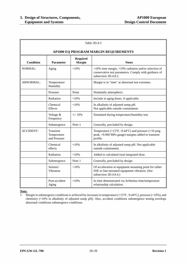
3. Design of Structures, Components, AP1000 European Equipment and Systems Design Control Document
EPS-GW-GL-700 3D-39 Revision 1
Table 3D.4-3
AP1000 EQ PROGRAM MARGIN REQUIREMENTS
Condition Parameter Required Margin Notes
NORMAL: Aging +10% +10% time margin, +10% radiation and/or selection of conservative test parameters. Comply with guidance of subsection 3D.4.8.2.
ABNORMAL: Temperature/ Humidity
Margin is in "time" at abnormal test extremes.
Pressure None Nominally atmospheric.
Radiation +10% Include in aging doses, if applicable.
Chemical Effects
+10% In alkalinity of adjusted sump pH. Not applicable outside containment.
Voltage & Frequency
+/- 10% Simulated during temperature/humidity test.
Submergence Note 1 Generally, precluded by design.
ACCIDENT: Transient Temperature and Pressure
Temperature (+15°F, -9.44°C) and pressure (+10 psig peak, +0.069 MPa gauge) margins added to transient profile.
Chemical effects
+10% In alkalinity of adjusted sump pH. Not applicable outside containment.
Radiation +10% Added to calculated total integrated dose.
Submergence Note 1 Generally, precluded by design.
Seismic/ Vibration
+10% Of acceleration at equipment mounting point for either SSE or line-mounted equipment vibration. (See subsection 3D.4.8.4.)
Post-accident Aging
+10% In time demonstrated via Arrhenius time/temperature relationship calculation.
Note: 1. Margin in submergence conditions is achieved by increases in temperature (+15°F, -9.44°C), pressure (+10%), and
chemistry (+10% in alkalinity of adjusted sump pH). Also, accident conditions submergence testing envelops abnormal conditions submergence conditions.

3. Design of Structures, Components, AP1000 European Equipment and Systems Design Control Document
EPS-GW-GL-700 3D-40 Revision 1
Table 3D.5-1 (Sheet 1 of 3)
NORMAL OPERATING ENVIRONMENTS
(Notes 1 and 2)
Location/Parameter Normal Range Notes
Zone 1 – Containment (Room numbers: 11000 through 11999)
Temperature 50° - 120°F (10° - 48.89°C) Pressure -0.2 - +1.0 psig (-0.001 - +0.007 MPa gauge) Humidity 0 - 100% Radiation see Table 3D.5-2 Chemistry None
Zone 2 - Auxiliary Building - Non-Radiological - I&C, DC Equipment, RCP Switchgear & Battery rooms, etc. (Room numbers: 12101, 12102, 12103, 12104, 12105, 12111, 12112, 12113, 12201, 12202, 12203, 12204, 12205, 12207, 12211, 12212, 12213, 12301, 12302, 12303, 12304, 12305, 12311, 12312, 12313, 12405, 12411, 12412, 12501, and 12505)
Temperature 67 - 73°F (19.44° - 22.78°C) Pressure Slightly positive to slightly negative Humidity 10 - 60% Radiation <103 rads (10 Gy) gamma Chemistry None
Zone 3 - Auxiliary Building - Non-Radiological - Main Control Room (Room number: 12400, 12401)
Temperature 67 - 78°F (19.44° - 25.56°C) Pressure Slightly positive Humidity 25 - 60% Radiation <103 rads (10 Gy) gamma Chemistry None
Zone 4 - Auxiliary Building - Non-Radiological - Accessible (Room numbers: 12321, 12421, 12422, 12423)
Temperature 50 - 105°F (10 - 40.56°C) Pressure Slightly positive Humidity 10 - 60% Radiation <103 rads (10 Gy) gamma Chemistry None

3. Design of Structures, Components, AP1000 European Equipment and Systems Design Control Document
EPS-GW-GL-700 3D-41 Revision 1
Table 3D.5-1 (Sheet 2 of 3)
NORMAL OPERATING ENVIRONMENTS
(Notes 1 and 2)
Location/Parameter Normal Range Notes
Zone 5 - Auxiliary Building - Non-Radiological - MSIV Compartments (Room numbers: 12404, 12406, 12504, 12506)
Temperature 50 - 130°F (10 - 54.44°C) Pressure Atmospheric Humidity 10 - 100% Radiation <103 rads (10 Gy) gamma Chemistry None
Zone 6 - Auxiliary Building - Radiological - Inaccessible (Room numbers: 12154, 12158, 12162, 12163, 12166, 12167, 12171, 12172, 12254, 12255, 12256, 12258, 12262, 12264, 12265, 12354, 12362, 12363, 12365, 12371, 12372, 12373, 12374, 12454, 12462, 12463)
Temperature 50 - 130°F (10 - 54.44°C) Pressure Slightly negative to atmospheric Humidity 10 - 100% Radiation See Table 3D.5-2 Chemistry None
Zone 7 - Auxiliary Building - Radiological - Accessible (Room numbers: 12151, 12152, 12155, 12156, 12161, 12169, 12241, 12242, 12244, 12251, 12252, 12261, 12268, 12271, 12272, 12273, 12274, 12275, 12341, 12351, 12352, 12361, 12451, 12452, 12461, 12551, 12552, 12553, 12554, 12555, 12561)
Temperature 50 - 104°F (10 - 40.00°C) Pressure Atmospheric Humidity 10 - 100% Radiation See Table 3D.5-2 Chemistry None
Zone 8 - Turbine Building (Room numbers: 20300 through 20799)
Temperature 50 - 104°F (10 - 40.00°C) Pressure Atmospheric Humidity 10 - 100% Radiation <103 rads (10 Gy) gamma Chemistry None
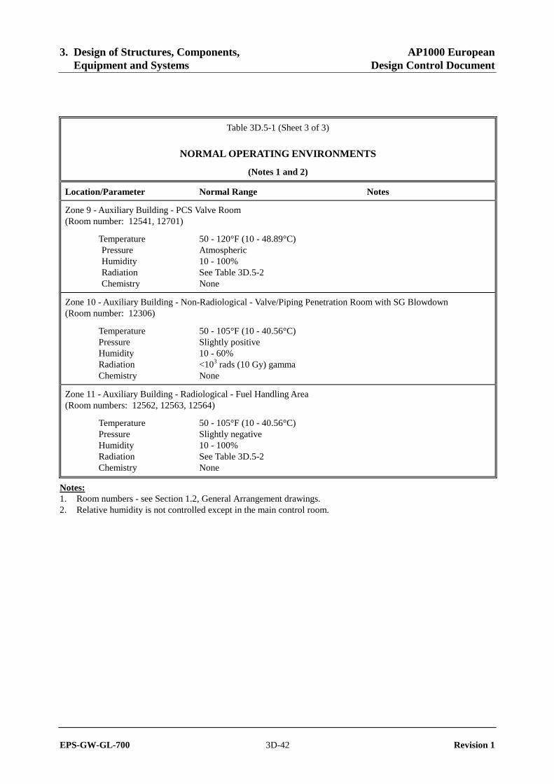
3. Design of Structures, Components, AP1000 European Equipment and Systems Design Control Document
EPS-GW-GL-700 3D-42 Revision 1
Table 3D.5-1 (Sheet 3 of 3)
NORMAL OPERATING ENVIRONMENTS
(Notes 1 and 2)
Location/Parameter Normal Range Notes
Zone 9 - Auxiliary Building - PCS Valve Room (Room number: 12541, 12701)
Temperature 50 - 120°F (10 - 48.89°C) Pressure Atmospheric Humidity 10 - 100% Radiation See Table 3D.5-2 Chemistry None
Zone 10 - Auxiliary Building - Non-Radiological - Valve/Piping Penetration Room with SG Blowdown (Room number: 12306)
Temperature 50 - 105°F (10 - 40.56°C) Pressure Slightly positive Humidity 10 - 60% Radiation <103 rads (10 Gy) gamma Chemistry None
Zone 11 - Auxiliary Building - Radiological - Fuel Handling Area (Room numbers: 12562, 12563, 12564)
Temperature 50 - 105°F (10 - 40.56°C) Pressure Slightly negative Humidity 10 - 100% Radiation See Table 3D.5-2 Chemistry None
Notes: 1. Room numbers - see Section 1.2, General Arrangement drawings. 2. Relative humidity is not controlled except in the main control room.

3. Design of Structures, Components, AP1000 European Equipment and Systems Design Control Document
EPS-GW-GL-700 3D-43 Revision 1
Table 3D.5-2
60-YEAR NORMAL OPERATING DOSES
Location
Gamma Dose Rate, [Rad air hour (Gy air hour)]
60-Year Gamma Dose, [Rads air hour (Gy air hour)]
Inside Containment:
RCS Pipe - Center 1.9x10³ (1.9x10) 1.0x10⁹ (1.0x10⁷)
RCS Pipe - ID 1.1x10³ (1.1x10) 5.7x10⁸ (5.7x10⁶)
RCS Pipe - OD (contact) 7.8x101 (0.78) 4.1x10⁷ (4.1x10⁵)
RCS Pipe - General Area(b) 4.0x101 (0.4) 2.1x10⁷ (2.1x10⁵)
Outside Loop/Compartment Wall <0.1 (<0.001) <5x10⁴ (<5x10²)
Adjacent to Reactor Vessel Wall 4.4x10⁴ (4.4x10²) 2.7x10¹⁰(a) (2.7x10⁸)
Outside Containment:
Penetration Area -- <1x10⁶ (1x10⁴)
Pump Cubicles -- <1x10⁶ (1x10⁴)
Radioactive Waste Area -- <1x10⁶ (1x10⁴)
Radwaste Tank Cubicles -- <1x10⁷ (1x10⁵)
Other General Areas -- <5x10² (5)
Notes: a. 60-year integrated neutron dose for E>1 MeV is 6x10¹⁷ n/cm2 b. 12 inches (304.8 millimeters) from RCS pipe OD
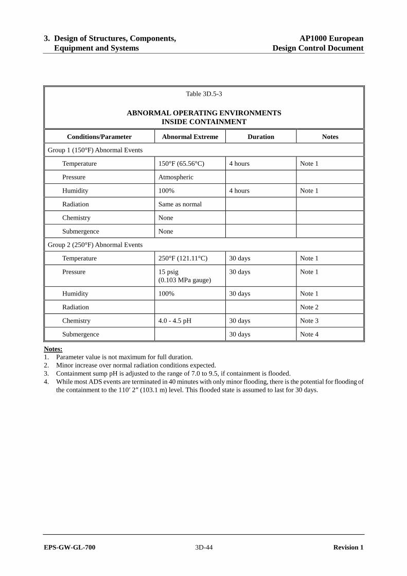
3. Design of Structures, Components, AP1000 European Equipment and Systems Design Control Document
EPS-GW-GL-700 3D-44 Revision 1
Table 3D.5-3
ABNORMAL OPERATING ENVIRONMENTS INSIDE CONTAINMENT
Conditions/Parameter Abnormal Extreme Duration Notes
Group 1 (150°F) Abnormal Events
Temperature 150°F (65.56°C) 4 hours Note 1
Pressure Atmospheric
Humidity 100% 4 hours Note 1
Radiation Same as normal
Chemistry None
Submergence None
Group 2 (250°F) Abnormal Events
Temperature 250°F (121.11°C) 30 days Note 1
Pressure 15 psig (0.103 MPa gauge)
30 days Note 1
Humidity 100% 30 days Note 1
Radiation Note 2
Chemistry 4.0 - 4.5 pH 30 days Note 3
Submergence 30 days Note 4
Notes: 1. Parameter value is not maximum for full duration. 2. Minor increase over normal radiation conditions expected. 3. Containment sump pH is adjusted to the range of 7.0 to 9.5, if containment is flooded. 4. While most ADS events are terminated in 40 minutes with only minor flooding, there is the potential for flooding of
the containment to the 110′ 2″ (103.1 m) level. This flooded state is assumed to last for 30 days.

3. Design of Structures, Components, AP1000 European Equipment and Systems Design Control Document
EPS-GW-GL-700 3D-45 Revision 1
Table 3D.5-4
ABNORMAL OPERATING ENVIRONMENTS OUTSIDE CONTAINMENT
Conditions/Parameter Abnormal Extreme Duration Notes
Zones 4, 5, 6, 7, 8, 9, 10 Same as normal
Zone 2 - Loss of HVAC - (I&C Rooms, DC Equipment Rooms) Note 4
Temperature Figure 3D.5-1 (Sheet 2) 7 days Note 3
Pressure Atmospheric
Humidity 40 - 95% Note 2
Radiation Same as normal
Chemistry None
Submergence None
Zone 3 - Loss of HVAC - (Main Control Room)
Temperature Figure 3D.5-1 (Sheet 1) 7 days
Pressure Atmospheric Note 1
Humidity 60 - 95% Note 2
Radiation Same as normal
Chemistry None
Submergence None
Zone 11 - Loss of AC Power - (Fuel Handling Area)
Temperature 212°F (100.00°C) maximum
Pressure Atmospheric Note 5
Humidity 100%
Chemistry None
Duration 2 weeks
Notes: 1. Main control room air pressure is maintained above a nominal value of atmospheric during accident conditions to
prevent radioactive contaminant entry. 2. Figure 3D.5-1 Sheets 1 and 2 have two curves post-72 hours. The high curve represents the introduction of outside
air that is high temperature, low humidity. The low curve represents the introduction of outside air that is low temperature, high humidity. The EQ Programs will include both of these extremes.
3. Test environments resulting from rooms with equipment supplied by 24- and 72-hour batteries are shown on Sheet 2 for the DC equipment rooms 12203 and 12207 and for the I&C rooms 12302 and 12304. The 24-hour battery is disconnected at 24 hours. The 72-hour battery is not disconnected. Environments resulting from rooms with equipment supplied by 24-hour batteries only, i.e., DC equipment rooms 12201 and 12205 and I&C rooms 12301 and 12305 are enveloped by the environments shown on Sheet 2.
4. Abnormal environments in other rooms within Zone 2 are the same as normal. 5. A relief panel is designed to open when the fuel handling area temperature exceeds 165°F (73.89°C).

3. Design of Structures, Components, AP1000 European Equipment and Systems Design Control Document
EPS-GW-GL-700 3D-46 Revision 1
Table 3D.5-5
ACCIDENT ENVIRONMENTS
(See Table 3D.5-1 for environmental zones)
Zone 1 - Inside Containment
Temperature, pressure and relative humidity See Figures 3D.5-6 and 3D.5-7 Radiation See Figures 3D.5-2 through 3D.5-5
Zones 2, 3, 4, 6, 7, 8, 9, 11
(Same as abnormal - see Table 3D.5-4)
Zones 5 and 10 - Outside Containment
MSIV Compartments
Temperature, pressure and relative humidity See Figure 3D.5-8 Radiation See Figures 3D.5-4 and 3D.5-5
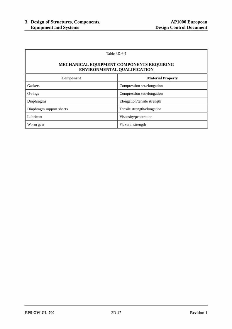
3. Design of Structures, Components, AP1000 European Equipment and Systems Design Control Document
EPS-GW-GL-700 3D-47 Revision 1
Table 3D.6-1
MECHANICAL EQUIPMENT COMPONENTS REQUIRING ENVIRONMENTAL QUALIFICATION
Component Material Property
Gaskets Compression set/elongation
O-rings Compression set/elongation
Diaphragms Elongation/tensile strength
Diaphragm support sheets Tensile strength/elongation
Lubricant Viscosity/penetration
Worm gear Flexural strength

3. Design of Structures, Components, AP1000 European Equipment and Systems Design Control Document
EPS-GW-GL-700 3D-48 Revision 1
Main Control Room
60
65
70
75
80
85
90
95
100
-12 12 36 60 84 108 132 156
Time (hr)
Tem
per
atu
re (
F)
Time: -12 to 0 hrsRelative Humidity: 60%
Time: 0 to 72 hrsRelative Humidity: 60%
Time: 72 to 168 hrsRelative Humidity: 70%
Time: 72 to 168 hrsRelative Humidity: 95%
Figure 3D.5-1 (Sheet 1 of 3)
Typical Abnormal Environmental Test Profile: Main Control Room
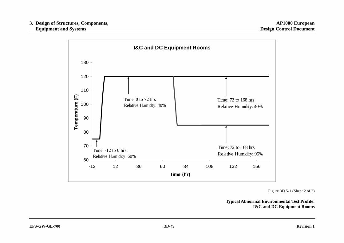
3. Design of Structures, Components, AP1000 European Equipment and Systems Design Control Document
EPS-GW-GL-700 3D-49 Revision 1
I&C and DC Equipment Rooms
60
70
80
90
100
110
120
130
-12 12 36 60 84 108 132 156
Time (hr)
Tem
per
atu
re (
F)
Time: -12 to 0 hrsRelative Humidity: 60%
Time: 0 to 72 hrsRelative Humidty: 40%
Time: 72 to 168 hrsRelative Humidity: 95%
Time: 72 to 168 hrsRelative Humidity: 40%
Figure 3D.5-1 (Sheet 2 of 3)
Typical Abnormal Environmental Test Profile: I&C and DC Equipment Rooms

3. Design of Structures, Components, AP1000 European Equipment and Systems Design Control Document
EPS-GW-GL-700 3D-50 Revision 1
Figure 3D.5-1 (Sheet 3 of 3)
Typical Abnormal Environmental Test Profile: Voltage and Frequency Variations

3. Design of Structures, Components, AP1000 European Equipment and Systems Design Control Document
EPS-GW-GL-700 3D-51 Revision 1
Gamma Dose Rate and Dose in Containment AirFollowing a Design Basis Accident
1.E+03
1.E+04
1.E+05
1.E+06
1.E+07
0.1 1 10 100 1000 10000
Time After Accident, hours
Inst
anta
neo
us
Do
se R
ate,
Rad
s-ai
r/h
ou
r
1.E+05
1.E+06
1.E+07
1.E+08
1.E+09
Inte
gra
ted
Do
se, R
ads-
air
DBA Instantaneous Gamma Dose
DBA Integrated Gamma Dose Rate
Figure 3D.5-2
Gamma Dose and Dose Rate Inside Containment After a LOCA

3. Design of Structures, Components, AP1000 European Equipment and Systems Design Control Document
EPS-GW-GL-700 3D-52 Revision 1
Beta Dose Rate and Dose in Containment AirFollowing a Design Basis Accident
1.E+04
1.E+05
1.E+06
1.E+07
1.E+08
0.1 1 10 100 1000 10000
Time After Accident, hours
Inst
anta
neo
us
Do
se R
ate,
Rad
s-ai
r/h
ou
r
1.E+06
1.E+07
1.E+08
1.E+09
1.E+10
Inte
gra
ted
Do
se, R
ads-
air
DBA - Instanteous Beta Dose Rate
DBA - Integrated Beta Dose
Figure 3D.5-3
Beta Dose and Dose Rate Inside Containment After a LOCA

3. Design of Structures, Components, AP1000 European Equipment and Systems Design Control Document
EPS-GW-GL-700 3D-53 Revision 1
Gamma Dose Rate and Dose Inside Containment Following a Steam Line Break Accident
1.E+00
1.E+01
1.E+02
1.E+03
1.E+04
0.1 1 10 100 1000 10000
Time After Accident, hours
Inst
anta
neo
us
Do
se R
ate,
Rad
s-ai
r/h
ou
r
1.E+02
1.E+03
1.E+04
1.E+05
1.E+06
Inte
gra
ted
Do
se, R
ads-
air
Steam Line Break - Instanteous Gamma Dose Rate
Steam Line Break - Integrated Gamma Dose
Figure 3D.5-4
Gamma Dose and Dose Rate Inside Containment After a Steam Line Break
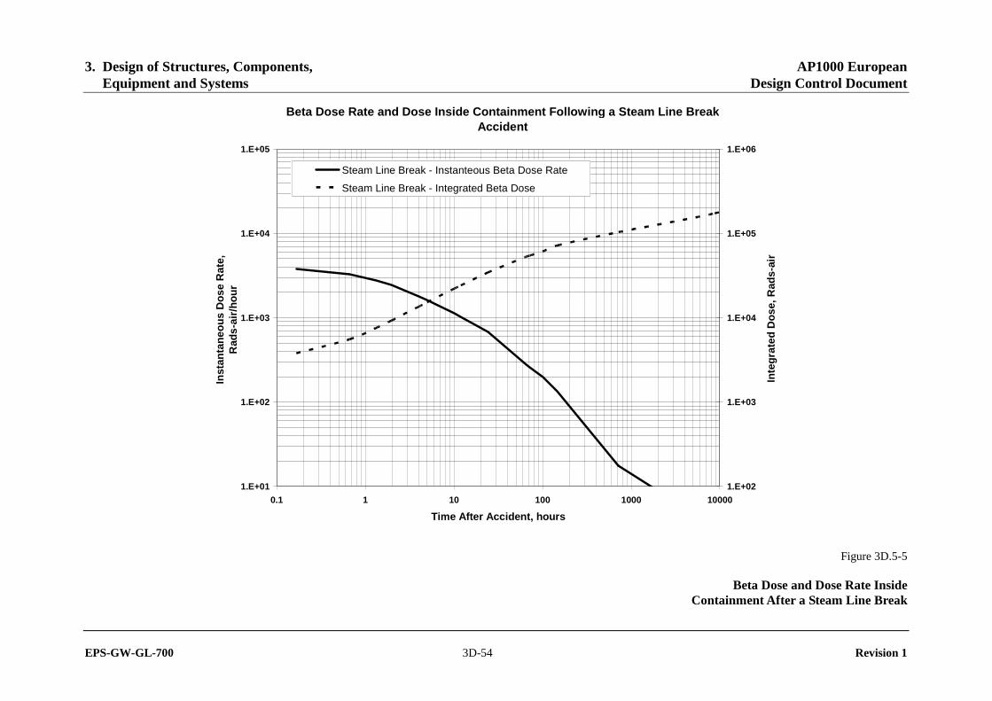
3. Design of Structures, Components, AP1000 European Equipment and Systems Design Control Document
EPS-GW-GL-700 3D-54 Revision 1
Beta Dose Rate and Dose Inside Containment Following a Steam Line Break Accident
1.E+01
1.E+02
1.E+03
1.E+04
1.E+05
0.1 1 10 100 1000 10000
Time After Accident, hours
Inst
anta
neo
us
Do
se R
ate,
Rad
s-ai
r/h
ou
r
1.E+02
1.E+03
1.E+04
1.E+05
1.E+06
Inte
gra
ted
Do
se, R
ads-
air
Steam Line Break - Instanteous Beta Dose Rate
Steam Line Break - Integrated Beta Dose
Figure 3D.5-5
Beta Dose and Dose Rate Inside Containment After a Steam Line Break
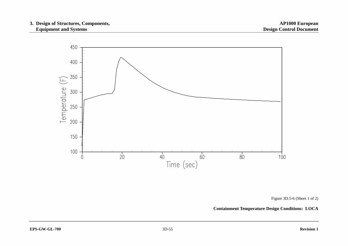
3. Design of Structures, Components, AP1000 European Equipment and Systems Design Control Document
EPS-GW-GL-700 3D-55 Revision 1
Figure 3D.5-6 (Sheet 1 of 2)
Containment Temperature Design Conditions: LOCA

3. Design of Structures, Components, AP1000 European Equipment and Systems Design Control Document
EPS-GW-GL-700 3D-56 Revision 1
Figure 3D.5-6 (Sheet 2 of 2)
Containment Pressure Design Conditions: LOCA

3. Design of Structures, Components, AP1000 European Equipment and Systems Design Control Document
EPS-GW-GL-700 3D-57 Revision 1
Figure 3D.5-7 (Sheet 1 of 2)
Containment Temperature Design Conditions: MSLB

3. Design of Structures, Components, AP1000 European Equipment and Systems Design Control Document
EPS-GW-GL-700 3D-58 Revision 1
Figure 3D.5-7 (Sheet 2 of 2)
Containment Pressure Design Conditions: MSLB

3. Design of Structures, Components, AP1000 European Equipment and Systems Design Control Document
EPS-GW-GL-700 3D-59 Revision 1
AP1000 Containment Temperature Curve
100
150
200
250
300
350
400
450
1 10 100 1000 10000 100000
Time (sec)
Tem
per
atu
re (F
)
MSLB DECLG LOCA DEHLG LOCA
Figure 3D.5-8 (Sheet 1 of 2)
Typical Combined LOCA/SLB/FLB Inside Containment Temperature

3. Design of Structures, Components, AP1000 European Equipment and Systems Design Control Document
EPS-GW-GL-700 3D-60 Revision 1
AP1000 Containment Pressure Curves
0
10
20
30
40
50
60
1 10 100 1000 10000 100000 1000000
Time (sec)
Pre
ssur
e (p
sig
)
MSLB DECLG LOCA DEHLG LOCA
Figure 3D.5-8 (Sheet 2 of 2)
Typical Combined LOCA/SLB/FLB Inside Containment Pressure

3. Design of Structures, Components, AP1000 European Equipment and Systems Design Control Document
EPS-GW-GL-700 3D-61 Revision 1
MSIV Compartment Response to MSLB
100
150
200
250
300
350
400
450
500
0 200 400 600 800 1000 1200 1400 1600
Time (sec)
Tem
per
atu
re (
F)
Figure 3D.5-9 (Sheet 1 of 2)
MSIV Compartment Response to MSLB (Short Term)

3. Design of Structures, Components, AP1000 European Equipment and Systems Design Control Document
EPS-GW-GL-700 3D-62 Revision 1
Long Term Temperature Return to Normal
0
50
100
150
200
250
300
350
1000 6000 11000 16000 21000 26000
Time (sec)
Tem
per
atu
re (F
)
Figure 3D.5-9 (Sheet 2 of 2)
MSIV Compartment Response to MSLB (Long Term)

3. Design of Structures, Components, AP1000 European Equipment and Systems Design Control Document
EPS-GW-GL-700 3D-63 Revision 1
ATTACHMENT A
SAMPLE EQUIPMENT QUALIFICATION DATA PACKAGE (EQDP)
The equipment qualification data package consists of the following elements:
Section 1.0–Specifications Section 2.0–Qualification Program Section 3.0–Qualification by Test Section 4.0–Qualification by Analysis Section 5.0–Qualification by Experience Section 6.0–Qualification Program Conclusions Table 1–Qualification Summary
3. Design of Structures, Components, AP1000 European Equipment and Systems Design Control Document
EPS-GW-GL-700 3D-64 Revision 1
EQDP-_______ Rev. _______ {date issued}
EQUIPMENT QUALIFICATION DATA PACKAGE
Equipment __________________________________________
Manufacturer __________________________________________
Model __________________________________________
Application __________________________________________
Environment: ____ Harsh ____ Mild
Prepared by: __________________________________________ {name}
Reviewed by: __________________________________________ {name}
Approved by: __________________________________________ {name}
This document provides or summarizes the seismic and environmental qualification of the equipment
identified above in accordance with the AP1000 EQ Program Methodology.
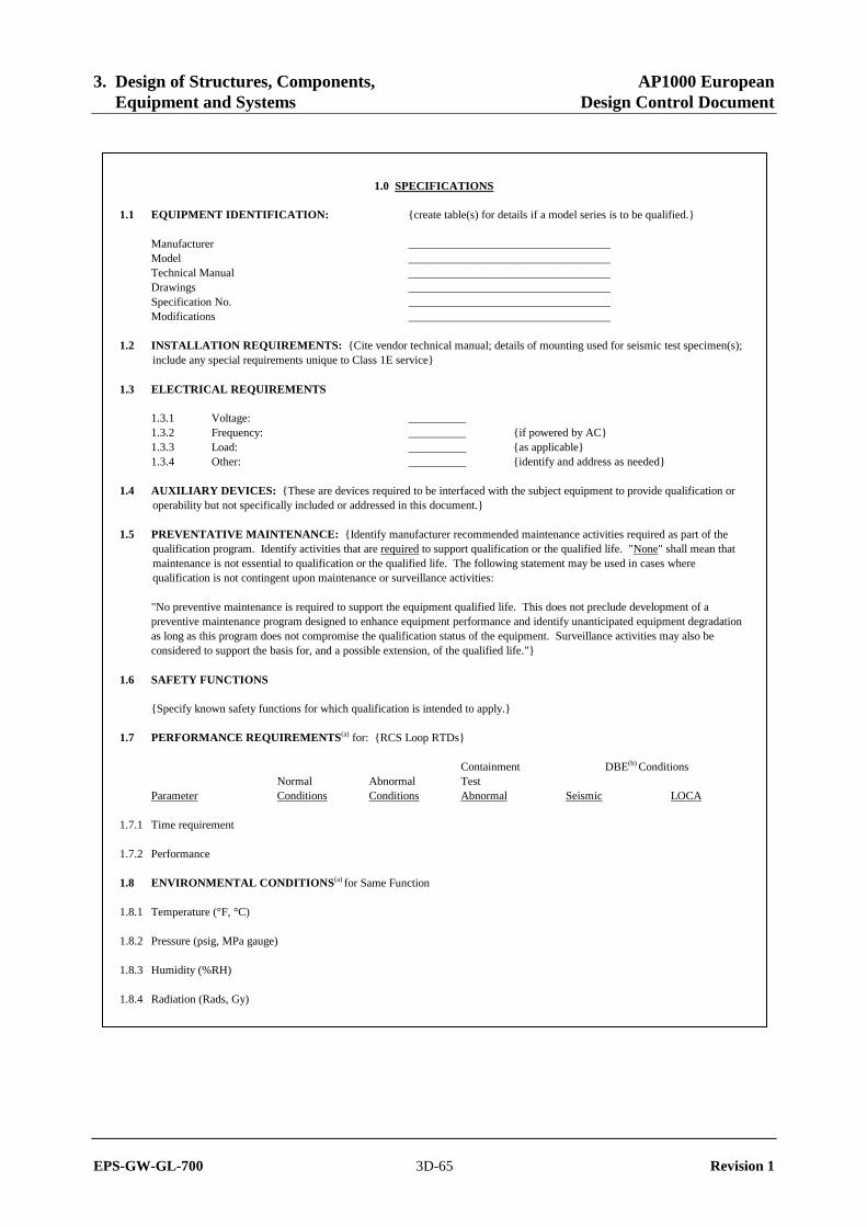
3. Design of Structures, Components, AP1000 European Equipment and Systems Design Control Document
EPS-GW-GL-700 3D-65 Revision 1
1.0 SPECIFICATIONS
1.1 EQUIPMENT IDENTIFICATION: {create table(s) for details if a model series is to be qualified.}
Manufacturer ___________________________________ Model ___________________________________ Technical Manual ___________________________________ Drawings ___________________________________ Specification No. ___________________________________ Modifications ___________________________________
1.2 INSTALLATION REQUIREMENTS: {Cite vendor technical manual; details of mounting used for seismic test specimen(s); include any special requirements unique to Class 1E service}
1.3 ELECTRICAL REQUIREMENTS
1.3.1 Voltage: __________ 1.3.2 Frequency: __________ {if powered by AC} 1.3.3 Load: __________ {as applicable} 1.3.4 Other: __________ {identify and address as needed}
1.4 AUXILIARY DEVICES: {These are devices required to be interfaced with the subject equipment to provide qualification or operability but not specifically included or addressed in this document.}
1.5 PREVENTATIVE MAINTENANCE: {Identify manufacturer recommended maintenance activities required as part of the qualification program. Identify activities that are required to support qualification or the qualified life. "None" shall mean that maintenance is not essential to qualification or the qualified life. The following statement may be used in cases where qualification is not contingent upon maintenance or surveillance activities:
"No preventive maintenance is required to support the equipment qualified life. This does not preclude development of a preventive maintenance program designed to enhance equipment performance and identify unanticipated equipment degradation as long as this program does not compromise the qualification status of the equipment. Surveillance activities may also be considered to support the basis for, and a possible extension, of the qualified life."}
1.6 SAFETY FUNCTIONS
{Specify known safety functions for which qualification is intended to apply.}
1.7 PERFORMANCE REQUIREMENTS(a) for: {RCS Loop RTDs}
Containment DBE(b) Conditions Normal Abnormal Test Parameter Conditions Conditions Abnormal Seismic LOCA
1.7.1 Time requirement
1.7.2 Performance
1.8 ENVIRONMENTAL CONDITIONS(a) for Same Function
1.8.1 Temperature (°F, °C)
1.8.2 Pressure (psig, MPa gauge)
1.8.3 Humidity (%RH)
1.8.4 Radiation (Rads, Gy)

3. Design of Structures, Components, AP1000 European Equipment and Systems Design Control Document
EPS-GW-GL-700 3D-66 Revision 1
1.8.5 Chemicals
1.8.6 Vibration
1.8.7 Acceleration (g)
Notes: a: Test margin is not included in the parameters of this section. b: DBE is the Design Basis Event.
{If more than one set of performance requirements and/or associated environmental conditions are to be specified, replicate these sections in pairs as "1.8 Performance ..." and "1.9 Environment ...", etc.}

3. Design of Structures, Components, AP1000 European Equipment and Systems Design Control Document
EPS-GW-GL-700 3D-67 Revision 1
2.0 QUALIFICATION PROGRAM
2.1 PROGRAM OBJECTIVE
The objective of this qualification program is to demonstrate, employing the recommended practices of Regulatory Guides 1.89 and 1.100 and IEEE 323-1974, 344-1987, {cite others as applicable} capability of the {Equipment description} to perform its/their safety related function(s) described in EQDP Section 1.7 while exposed to the applicable conditions and events defined in EQDP Section 1.8.
{Narrative should introduce an outline of the program plan. Table below to be completed as graphic reference. Table shall not be abbreviated; items must appear and be addressed by direct response.}
2.2 REFERENCES
{List test report(s) and information sources cited in this document}
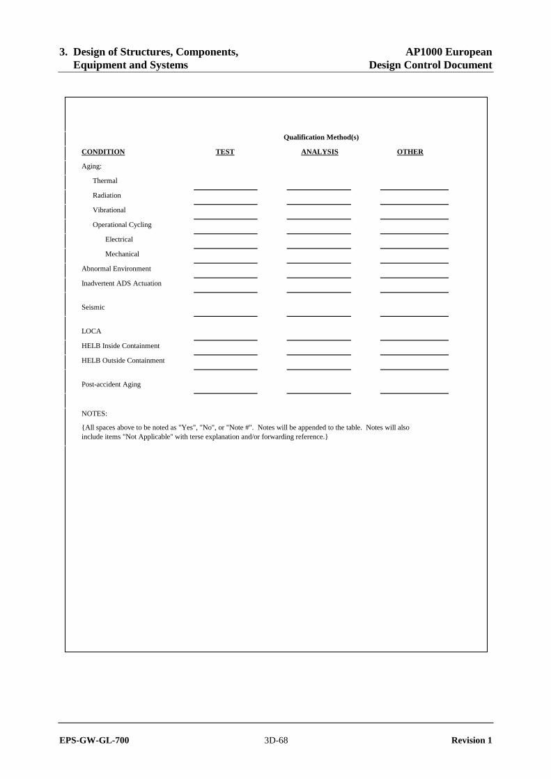
3. Design of Structures, Components, AP1000 European Equipment and Systems Design Control Document
EPS-GW-GL-700 3D-68 Revision 1
Qualification Method(s)
CONDITION TEST ANALYSIS OTHER
Aging:
Thermal
Radiation
Vibrational
Operational Cycling
Electrical
Mechanical
Abnormal Environment
Inadvertent ADS Actuation
Seismic
LOCA
HELB Inside Containment
HELB Outside Containment
Post-accident Aging
NOTES:
{All spaces above to be noted as "Yes", "No", or "Note #". Notes will be appended to the table. Notes will also include items "Not Applicable" with terse explanation and/or forwarding reference.}

3. Design of Structures, Components, AP1000 European Equipment and Systems Design Control Document
EPS-GW-GL-700 3D-69 Revision 1
3.0 QUALIFICATION BY TEST (TEST PLAN AND SUMMARY)
3.1 SPECIMEN DESCRIPTION
{Identify the item or items to be tested}
3.2 NUMBER TESTED
{If more than one type is to be tested, identify how many of each. Subsequent Sections should clarify specifics for each.}
3.3 MOUNTING
{Identify specific seismic mounting details, referencing applicable drawings, instructions, documents. Note existence of differences from manufacturer recommendations}
3.4 CONNECTIONS
{Identify interfaces, both electrical and mechanical, identify any connectors or sealing assemblies used which are not provided with the equipment, or are not covered by this qualification.
3.5 TEST SEQUENCE PREFERRED
This section identifies the preferred test sequences as specified in IEEE 323-1974.
3.5.1 Inspection of Test Item 3.5.2 Operation (Normal Condition) 3.5.3 Operation (Performance Specifications Extremes: Section 1) 3.5.4 Simulated Aging 3.5.5 Vibration/Seismic 3.5.6 Operation (Simulated High Energy Line Break Conditions) 3.5.7 Operation (Simulated Post-HELB Conditions) 3.5.8 Inspection
3.6 TEST SEQUENCE ACTUAL
This section identifies the actual test sequence which constitutes the qualification program for this equipment. A justification for anything other than the preferred sequence is provided.
Test Sequence (from Section 3.5):
{List and explain; provide forwarding references to subsequent subsections as necessary}

3. Design of Structures, Components, AP1000 European Equipment and Systems Design Control Document
EPS-GW-GL-700 3D-70 Revision 1
3.7 SERVICE CONDITIONS TO BE SIMULATED BY TEST(1)
Normal Abnormal Seismic HELB Post-HELB
3.7.1 Temperature (°F, °C)
3.7.2 Pressure (psig, MPa gauge)
3.7.3 Humidity (% RH)
3.7.4 Radiation (Rads, Gy)
3.7.5 Chemicals
3.7.6 Vibration
3.7.7 Seismic (g)
(1) Test parameter margins are included for the worst-case known requirements applicable to the equipment type. Margin for a specific parameter is dependent on the requirements of each application or location for the equipment; these may vary.
(2) Post-accident operability addressed through simulated thermal aging. Temperature and other parameters are selected to envelop the requirements.

3. Design of Structures, Components, AP1000 European Equipment and Systems Design Control Document
EPS-GW-GL-700 3D-71 Revision 1
3.8 MEASURED VARIABLES
This section tabulates the variables and parameters required to be measured during each of the following tests in the qualification test sequence.
Tests: {example} A: Thermal Aging B: Mechanical Cycling C: Irradiation D: Seismic Test E: HELB Test
3.8.1 Category I – Environment Required Not Required
3.8.1.1 Temperature ... ... 3.8.1.2 Pressure ... ... 3.8.1.3 Moisture ... ... 3.8.1.4 Gas Composition ... ... 3.8.1.5 Vibration ... ... 3.8.1.6 Time ... ...
3.8.2 Category II – Input Electrical Characteristics
3.8.2.1 Voltage ... ... 3.8.2.2 Current ... ... 3.8.2.3 Frequency ... ... 3.8.2.4 Power ... ... 3.8.2.5 Other ... ...
3.8.3 Category III – Fluid Characteristics
3.8.3.1 Chemical Composition ... ... 3.8.3.2 Flow Rate ... ... 3.8.3.3 Spray ... ... 3.8.3.4 Temperature ... ...
3.8.4 Category IV – Radiological Features
3.8.4.1 Energy Type ... ... 3.8.4.2 Energy Level ... ... 3.8.4.3 Dose Rate ... ... 3.8.4.4 Integrated Dose ... ...
3.8.5 Category V – Electrical Characteristics
3.8.5.1 Insulation Resistance ... ... 3.8.5.2 Output Voltage ... ... 3.8.5.3 Output Current ... ... 3.8.5.4 Output Power ... ... 3.8.5.5 Response Time ... ... 3.8.5.6 Frequency Characteristics ... ... 3.8.5.7 Simulated Load ... ...

3. Design of Structures, Components, AP1000 European Equipment and Systems Design Control Document
EPS-GW-GL-700 3D-72 Revision 1
Required Not Required
3.8.6 Category VI – Mechanical Characteristics
3.8.6.1 Thrust ... ... 3.8.6.2 Torque ... ... 3.8.6.3 Time ... ... 3.8.6.4 Load Profile ... ...
3.8.7 Category VII – Auxiliary Equipment
3.8.7.1 {as applicable, also see ... ... Section 1.4 of EQDP}

3. Design of Structures, Components, AP1000 European Equipment and Systems Design Control Document
EPS-GW-GL-700 3D-73 Revision 1
3.9 TYPE TEST SUMMARY
3.9.1 Normal Environment Testing
Operation of the {equipment} under normal conditions is demonstrated by {discuss test, checks, et. al. which provide baseline performance data} ... , as reported in Reference .
3.9.2 Abnormal Environment Testing
Operation of the {equipment} under abnormal conditions is demonstrated by {discuss test, checks, et. al. which provide baseline performance data} ... , as reported in Reference .
3.9.3 Aging Simulation Procedure
{Describe the aging mechanisms simulated and the sequence, including justifications as necessary.}
The test units were pre-conditioned to simulate an aged condition prior to subjecting them to the Design Basis Event (DBE) seismic and environmental conditions/simulation. The aged condition was achieved by separate phases of {accelerated thermal aging, thermal cycling, and radiation exposure to a total integrated gamma dose equivalent to a twenty-year normal dose plus the design basis accident dose, and accelerated flow induced and pipe vibration simulation}. Through all the pre-conditioning phases, the {equipment, performance} were monitored to verify {continuous operation}.
3.9.3.1 Design Life: {Also, justification of the bases for a design life goal should be provided, when used in mild-environment programs. Generally inapplicable to harsh-environment programs.}
3.9.3.2 Shelf Life: {Though not typically applicable, state any limitation in life, as well as conditions which may be detrimental if known.}
3.9.3.3 Thermal Aging: The qualified life is years based on an ambient temperature of { °C ( °F) and a °C temperature rise due to }. Calculations are based on a test temperature of , test duration of hours, and an activation of eV (See References x, et al.)}.
3.9.3.4 Radiation Aging: The qualified life is limited by the expected radiation during the -year life and the Design Basis Event. {Subtract accident TID from qualified TID; account for margin, remainder is to be compared to normal/abnormal radiation requirements to yield life limits.}
3.9.3.5 Operating Cycles: {Expected number of electrical and/or mechanical cycles, or numbers of actuations, as applicable. Estimated on the basis of the expected for the design, qualified, installed life of the equipment. Specification may be on a per annum or a per fuel cycle basis. Compare to cycle life data from test.}
3.9.3.6 Vibration Aging: {present bases; refer to test profile and/or Subsection 3.9.4}.
3.9.4 Seismic Tests
The seismic testing reported in Reference x was completed on aged equipment employing {method(s)} in accordance with Regulatory Guide 1.100 and IEEE 344-1987. ... {Summarize equipment condition and/or performance versus the acceptance criteria.} ... Actual margin should be determined for each application/location throughout the plant and verified to meet or exceed the margin requirements.
{Discuss or reference discussion of test anomalies.}
3. Design of Structures, Components, AP1000 European Equipment and Systems Design Control Document
EPS-GW-GL-700 3D-74 Revision 1
3.9.5 High Energy Line Break/Post HELB Simulation
The {equipment} were subjected to the HELB simulation temperature/pressure profile of Figure x. Following the °F (___ °C) temperature peak, the temperature gradually declines to °F (___ °C) and is held at saturated steam conditions for days, simulating a period of Post-HELB operation. The test data and activation energy specified in Subsection 3.9.3.3 can be used to determine margin in post-accident aging for each application/location of the equipment.
{Summarize equipment condition and/or performance versus the criteria}
{Discuss or reference discussion of test anomalies.}

3. Design of Structures, Components, AP1000 European Equipment and Systems Design Control Document
EPS-GW-GL-700 3D-75 Revision 1
4.0 QUALIFICATION BY ANALYSIS
The AP1000 EQ Program does permit qualification solely on the basis of analyses for equipment outside the scope of 10CFR50.49. The following subsections discuss each of the analyses preformed, its test basis and justification, and summarizes conclusions documented in References x; et. al., which provided detailed accounts of each analysis.
{Each subsection will address a particular analysis, if more than one is performed to support qualification.}
4.x (EXAMPLE)
{The purpose and objective will be identified here. Subsections will provide necessary details per the following format.}
4.x.1 {Equipment, Characteristic or Aspect} Analyzed
{A general description of the equipment and its function based on applicable equipment and mounting drawings, and purchase orders.}
4.x.2 Equipment Specification(s)
{The applicable design standards shall be documented including any limitations imposed by the equipment specification. Installation detail considered or represented are to be included.}
4.x.3 Methods and Codes
{Description of analytical methods or techniques, computer program, mathematical model(s) used, and the method(s) of verification}
4.x.4 Acceptance Criteria
{The specific safety function(s), postulated failure modes, or the failure effects to be demonstrated by analysis.}
4.x.5 Model
{Description of mathematical model of equipment or feature analyzed.}
4.x.6 Assumptions and Justifications
{EXAMPLES: Description of the loading conditions to be used. Summary of stresses to be considered.}
4.x.7 Impact to Safety Function
{Summarize analytically established performance characteristics and their acceptability. Discussion and summary of the analytical results which demonstrate equipment structural integrity and, where appropriate, operability. Particular to cabinets, critical deflections should be determined and included in mounting requirements for spacing with respect to other equipment and structures.}
4.x.8 Conclusions
{Descriptive summary, including any conditions imposed on qualification or use; qualified life, limitations, surveillance/maintenance requirements, et. al.} Further discussion of this analysis is presented in Reference x.
4.Y ENVIRONMENTAL QUALIFICATION ANALYSIS FOR {VALVE SOFT PARTS}
{purpose and objective}
4.Y.1 Equipment Identification
{Per Subsection 6.2.3.1}
3. Design of Structures, Components, AP1000 European Equipment and Systems Design Control Document
EPS-GW-GL-700 3D-76 Revision 1
4.Y.2 Component Identification
{Per Subsection 6.2.3.1}
4.Y.3 Safety Related Functions
{Per Subsection 6.2.3.2}
4.Y.4 Component Acceptance Criteria
{Per Subsection 6.2.3.3}
4.Y.5 Service Conditions
{Per Subsection 6.2.3.4}
4.Y.6 Potential Failure Modes
{Per Subsection 6.2.3.5}
4.Y.7 Identify the Environmental Effects on Material Properties
Each non-metallic, including lubricants, is evaluated to determine the effect of the environmental conditions on the material properties. For each non-metallic, a radiation threshold level and maximum service temperature is identified.
The radiation threshold level and the maximum service temperature are identified using materials handbooks, textbooks, government and industry reports, and laboratory data. If the evaluation indicates that the lowest levels may be exceeded for certain equipment, higher levels are identified at which varying degrees of material degradation may occur.
Mechanical equipment is highly resistive to degradation due to elevated humidity levels: therefore, relative humidity is not included as a parameter to be evaluated for environmental qualification. Pressure can be discounted for most equipment types, as there are no foreseen failures due to elevated pressure levels for most mechanical equipment. However, pressure must be addressed in the evaluation.
The susceptibility of the non-metallic material to the chemicals due to the design basis accident and exposure to the process fluid is evaluated. The material information in the chemical handbooks is an acceptable source of qualification documentation.
4.Y.7.1 Perform Thermal Aging Analysis
Aging analysis is performed for organic materials. Mineral-based subcomponents are not considered to be sensitive to thermal aging during the design life of a plant and, therefore, are not analyzed.
Aging in mechanical components is associated with corrosion, erosion, particle deposits and embrittlement. In new construction, corrosion and erosion are considered by providing additional material thickness as a corrosion or erosion allowance above the required design. The other aging phenomena are considered during inservice inspections of operating components in accordance with ASME Code, Section XI. Aging qualification of metallic parts of equipment except for corrosion and erosion is in compliance with ASME Code, Section XI, therefore aging effects on metallic components are not addressed herein.
The non-metallic material analysis for determining the expected qualified thermal life is performed using Arrhenius methodology. The thermal input during the operating time, as explained below, is deducted from the tested thermal aging of the material at service temperature to obtain the qualified life.
The component is evaluated for the specified post-accident operating time. The thermal input from the postulated accident profile (i.e., LOCA/MSLB) for the duration of the specified operating time is compared to the material thermal aging data. The Arrhenius model is used to perform this comparison. The component is evaluated for the maximum post-accident operating time unless a system analysis is performed to justify shorter operating times.

3. Design of Structures, Components, AP1000 European Equipment and Systems Design Control Document
EPS-GW-GL-700 3D-77 Revision 1
Analysis of the non-metallics should also take into account any degradation of the part due to its use in dynamic modes (i.e., moving part).
4.Y.7.2 Evaluate the Environmental Effects on Equipment Safety-Related Function
A conservative initial screening of the non-metallic subcomponents is made by comparison of the material capabilities (threshold radiation level and maximum service temperature) with the maximum postulated environmental conditions. If the threshold radiation values and the maximum service temperatures are above the maximum postulated environmental conditions, and if the material aging analysis demonstrates a service life sufficient to survive the accident duration, then the material is considered acceptable.
Those items which are not shown to be acceptable based on the above comparison are evaluated in further detail regarding:
- extent of material degradation - material properties affected - equipment/subcomponent function - extent of equipment functional degradation - location-specific environmental conditions
4.Y.8 Conclusions
{Per subsection 3D.6.2.3.7}
4.Y.9 EQ Maintenance Requirements
{Per subsection 3D.6.2.3.8}

3. Design of Structures, Components, AP1000 European Equipment and Systems Design Control Document
EPS-GW-GL-700 3D-78 Revision 1
5.0 QUALIFICATION BY EXPERIENCE
This method of qualification is not used.

3. Design of Structures, Components, AP1000 European Equipment and Systems Design Control Document
EPS-GW-GL-700 3D-79 Revision 1
6.0 QUALIFICATION PROGRAM CONCLUSIONS
6.1 AGING
{Discuss specifics and state on limitations or requirements; specifics with respect to:
• Design Life Goal
• Thermal Aging
• Radiation Aging
• Operating Cycles
• Vibration Aging}
6.2 DBE QUALIFICATIONS
6.3 PROGRAM CONCLUSIONS
The qualification of the {equipment} is demonstrated by the completion of the simulated aging and Design Basis Event testing described herein and reported in Reference {1}.
{State any conditions imposed on qualification or qualified life, cite any lessons learned which necessitate future user actions to preserve continued qualification}
{Refer to Table 1}

3. Design of Structures, Components, AP1000 European Equipment and Systems Design Control Document
EPS-GW-GL-700 3D-80 Revision 1
Table 1
QUALIFICATION SUMMARY
SYSTEM {RPS} CATEGORY Category(1) {a} LOCATION {Containment bldg.} STRUCTURE/AREA {Zone Number} EQUIPMENT TYPE {pressure transmitter } MANUFACTURER { } MODEL { }
QUAL ENVIRONMENTAL EXTREMES PARAMETER METHOD(2) QUALIFIED(3) SPECIFIED(4) NOTES
NORMAL
ABNORMAL
QUALIFIED LIFE {5}
SEISMIC {Both} Figure x {Ref; Fig.}
ACCIDENT Figure x {Ref; Fig.} Temperature {Test} °F (°C) Pressure {Test} psig (MPa gauge) Rel. humidity {Test} % Radiation {Both} E+06 R(γ) (Gy) {Both} E+06 R(β) (Gy) Chemistry {Test} {Note 6} Operability {Both} Accuracy {Test} NOTES: 1. Equipment category as per NUREG-0588, Appendix E, Section 2. 2. Qual. Methods are: Test, Analysis, Both (Test & Anal.), or Other. 3. Qualified values are test extremes which include margin. 4. Environmental parameters for the plant location are to be inserted. If more than one applicable, most extreme are to be cited 5. Qualified life estimated on basis of maximum normal temperature of °C ( °F) and a temperature rise of °C ( °F). 6. Chemistry Conditions: {pH and composition}.

3. Design of Structures, Components, AP1000 European Equipment and Systems Design Control Document
EPS-GW-GL-700 3D-81 Revision 1
ATTACHMENT B
AGING EVALUATION PROGRAM
B.1 Introduction
As stated in IEEE 323, aging of Class 1E equipment during normal service is considered as an integral part of the qualification program. The objective is not to address random age-induced failures that occur in-service and are detected by periodic testing and maintenance programs. The objective is to address the concern that some aging mechanisms, when considered in conjunction with the specified design basis events (DBE), may have the potential for common mode failure.
The AP1000 equipment qualification program addresses the aging concern and makes maximum use of available data and experience on aging mechanisms. This approach places primary emphasis on common mode failures due to enveloping design basis events. For example, reasonable assurance against common mode failures being induced because of a loss of heating, ventilation, and air conditioning (HVAC) is provided by adequate design, normal maintenance, and calibration procedures.
B.2 Objectives
The objectives of the aging evaluation program follow:
• To establish, where possible, the effects of the degradation due to aging mechanisms that occur before the occurrence of an accident, when safety-related equipment is called upon to function
• To provide increased confidence that safety-related equipment performs its safety-related function under the specified service condition.
B.3 Basic Approach
The general approach to addressing aging allocates equipment to one of two subprograms (A or B).
• Subprogram A includes electrical equipment required to perform a safety-related function in a high-energy line break (HELB) environment. For this equipment an aging simulation is included as part of the equipment qualification test sequence. The equipment is energized during the aging simulation.
• Subprogram B includes equipment required to mitigate high-energy line breaks but which, due to its location, is isolated from any adverse external environment resulting from the accident. For equipment in Subprogram B the single design basis event capable of producing an adverse environment at the equipment location is the seismic event. Aging, for Subprogram B, is not included in the equipment qualification test sequence. Significant aging mechanisms are determined by evaluation of available test data. Generally, this data is from separate programs conducted to demonstrate that aged components continue to meet manufacturer's performance specifications under applicable seismic design basis event

3. Design of Structures, Components, AP1000 European Equipment and Systems Design Control Document
EPS-GW-GL-700 3D-82 Revision 1
conditions and that seismic testing of unaged equipment is not invalidated by anticipated aging mechanisms.
B.4 Subprogram A
Electrical equipment required to perform a safety-related function in a high-energy line break (such as a loss of coolant accident, feed line break, or steam line break) environment is included in Subprogram A. This subprogram provides for an aging simulation to be included in the equipment's qualification test sequence.
B.4.1 Scope
The typical equipment scope and aging mechanisms applied under Subprogram A are shown in Tables 3D.B-1 and 3D.B-2, respectively. The equipment selected is that Class 1E equipment qualified to operate in a high-energy line break environment. The aging mechanisms discussed next are those to which the equipment may be potentially sensitive in its installed location.
B.4.2 Aging Mechanisms
The aging mechanisms that could potentially affect electrical equipment in Subprogram A are discussed under the following headings:
Time, in conjunction with:
• Operational stresses (current, voltage, operating cycles, Joulean self-heating)
• (External stresses (thermal, vibration, radiation, humidity, seismic).
The aging mechanisms considered potentially significant and to be simulated are identified in Table 3D.B-2 for each item of equipment in Subprogram A. Where applied, the aging mechanisms are simulated as described in the following discussions.
B.4.3 Time
For equipment subject to high-energy line break conditions, the most significant in-service aging mechanisms (that is, radiation and thermal) come into effect during reactor operation. Consequently, it can be assumed that the "aging clock" starts on plant startup.
B.4.4 Operational Stresses
Electrical Cycling
Electrical supplies to safety-related equipment are, in general, highly stable. So aging effects due to supply cycling during service are not anticipated. Where the equipment is anticipated to experience multiple startup and shutdown cycles, the equipment is electrically cycled to simulate the number of anticipated startup and shutdown cycles plus 10 percent.

3. Design of Structures, Components, AP1000 European Equipment and Systems Design Control Document
EPS-GW-GL-700 3D-83 Revision 1
Mechanical Cycling
Aging effects resulting from anticipated mechanical cycling of the equipment are simulated by applying, as a minimum, the number of cycles estimated to occur during the target qualified life plus 10 percent. Mechanical cycling covers such operations as switching and relay actuation.
Joulean Self-Heating
Where the equipment is not aged in a live condition, the aging effects resulting from Joulean self-heating are recognized by employing the equipment operating temperature as the datum temperature for assessing the accelerated thermal aging parameters to be employed.
B.4.5 External Stresses
Thermal Effects
Thermal effects are considered one of the most significant aging mechanisms to address. The equipment is thermally aged to simulate an end-of-qualified-life condition using the Arrhenius model to establish the appropriate conditioning period at elevated temperature. Where data is not available to establish the model parameters for the materials employed, a verifiably conservative value of 0.5 eV (8.011 E-20J) is used for activation energy (Attachment D).
For each piece of equipment an appropriate normal and abnormal operating temperature and an associated time history are determined for inclusion in the Arrhenius model. The equipment temperature is determined by the addition of an appropriate equipment specific ΔT to the external ambient temperature. Attachment D also provides information concerning the determination of appropriate ambient temperatures and time-temperature histories for use in thermal aging evaluation of equipment. Post-accident thermal aging is included by recognizing the higher post-accident ambient temperatures in determining the parameters employed for the post-accident accelerated thermal aging simulation.
In-Service Vibration
The majority of safety-related electrical equipment has a proven history of in-plant service. Thus, it is unlikely that a significant, undetected, failure mechanism exists because of low-level, in-plant vibration. In addition, a simulation of earthquakes smaller than the safe shutdown earthquake (SSE) employed during equipment and component seismic testing give added confidence that this potential aging mechanism is covered (See Attachment E, Section 4.4). For line-mounted equipment, in-service pipe and flow induced vibration may be significant. As a consequence, an additional vibration aging step is included in the aging sequence as indicated for certain items of equipment in Table 3D.B-2. (See Attachment E, Section 5.2.4.)
Radiation
Radiation during normal operation is not considered an aging mechanism for equipment subject to in-service integrated doses less than 104 rads (100 Gy). Research has established that no aging mechanisms are measurable below 104 rads (100 Gy) (Attachment C) for materials and most components supplied in safety-related electrical equipment. Some devices may have performance

3. Design of Structures, Components, AP1000 European Equipment and Systems Design Control Document
EPS-GW-GL-700 3D-84 Revision 1
limitations below 104 rads (100 Gy). For radiation doses in excess of 104 rads (100 Gy), the equipment is irradiated using a gamma (γ) source to a dose equivalent to the estimated dose to be incurred during normal operation for the target qualified life. The estimated doses employed are specified in the equipment qualification data package, Section 1.8.4, and are based on a 100 percent load factor, including appropriate margin. For Subprogram A equipment, the equivalent accident dose is usually applied before design basis event testing.
Humidity
The use of materials significantly affected by humidity is avoided. For equipment subject to high energy line break environments, the aging effects due to humidity during normal operation are judged to be insignificant compared to the effects of the high-temperature steam accident simulation. Therefore, no additional humidity aging simulation is required.
Seismic Aging
The potential aging effects of low-level seismic activity and some low-level, in-plant vibration are addressed by employing a simulation of five earthquakes of 50 percent of the magnitude of a safe shutdown earthquake before seismic testing of the aged equipment.
B.4.6 Synergism
An important consideration in aging is the possible existence of synergistic effects when multiple stress environments are applied simultaneously. The potential for significant synergistic effects is addressed by the conservatisms inherent in using the "worst-case" aging sequence, conservative accelerated aging parameters and conservative, design basis event test levels which provide confidence that any synergistic effects are enveloped.
B.4.7 Design Basis Event Testing
Design basis event testing subsequent to equipment aging is discussed in Appendix 3D as to guidelines for defining high-energy line break environments and seismic conditions. Testing for equipment specific test environments and seismic parameters is discussed in Attachment A, Section 3.0.
B.4.8 Aging Sequence
The aging mechanisms applied to equipment subject to high-energy line break environments are determined by definition of the aging environments at the equipment location and by a subsequent evaluation of the sensitivity of the equipment to these environments. If the sensitivity of the equipment is not known, aging mechanisms are simulated by conservative methods as previously described. Those aging mechanisms that are simulated for typical equipment subject to high-energy line break environments are shown in Table 3D.B-2.
The order in which each of the aging mechanisms is applied is as shown in Table 3D.B-2. This order is considered to be conservative, as no aging mechanism is anticipated to be capable of reducing the impact of the previously applied mechanisms. As an example, thermal aging is applied before radiation aging to preclude the annealing out of radiation-induced defects.
3. Design of Structures, Components, AP1000 European Equipment and Systems Design Control Document
EPS-GW-GL-700 3D-85 Revision 1
Similarly, the effects of mechanical aging are considered more significant when applied to equipment that has already been preaged to address thermal and radiation phenomena.
B.4.9 Performance Criterion
The basic acceptance criterion is that the qualification tests demonstrate the capability of the aged equipment to perform prespecified, safety-related functions consistent with meeting the performance specification of Attachment A, Section 1.7 of the applicable equipment qualification data packages while exposed to the associated environmental conditions defined in Attachment A, Section 1.8.
B.4.10 Failure Treatment
When thermal aging is simulated at an equipment level, a conservative value for the activation energy is assumed for the components composing the equipment. As a consequence, many components are grossly overaged, and failure of some of the components is expected during the aging simulation. When three test units are preaged, in the event of such failure(s), one of the following options is selected.
• when a particular component fails in one of the three test units, the failure is considered random. The failed component is replaced by a new component, and the test is continued
• when a particular component fails in more than one of the three test units, either:
1. the failed components are replaced by new identical components and the aging simulation continued. The claimed qualified life of the unit is consistent with the minimum aging period simulated by at least two of the three units; or
2. the failed components is replaced by identical components specifically aged to the qualified life by assuming for thermal aging a less conservative activation energy specifically determined for the component, or
3. the failed components are replaced by a different type of component which is aged for a period equal to the test units.
When less than three test samples prevent such a conclusion from being reached, any failures are investigated to ascertain whether the failure mechanism is of common mode origin. Should a common mode failure mechanism be identified as having caused the failure, a design change is implemented to eliminate the problem. Supplemental or repeat tests will be completed to demonstrate compliance with the acceptance criteria.
B.5 Subprogram B
Subprogram B includes Class 1E equipment not required to perform a safety related function in a high-energy line break environment. It involves a review of available information to demonstrate the absence of significant in-service aging mechanisms. For equipment allocated to this subprogram, the single design basis event capable of producing an adverse environment at the equipment location is the seismic event. Seismic testing completed on unaged equipment is

3. Design of Structures, Components, AP1000 European Equipment and Systems Design Control Document
EPS-GW-GL-700 3D-86 Revision 1
verified as valid by demonstrating via this subprogram that no available information suggests that aged materials and components would not continue to meet their design specification during a seismic event.
B.5.1 Scope
Subprogram B includes both a review of material analysis and the results of a component testing program for equipment not required to perform a safety-related function in a high-energy line break environment. Equipment is included that is required to mitigate high-energy line breaks but which, because of the equipment location, is isolated from the adverse environment resulting from the accident. Typical equipment allocated to Subprogram B is identified in Table 3D.B-1.
B.5.2 Performance Criteria
Available Material Analysis – For equipment and components for which aging is addressed by evaluation of appropriate mechanisms, the basic performance criterion is that the evaluation of test data demonstrates the effect of aging is minor and does not affect the capability of the aged equipment to perform prespecified functions. This is consistent with meeting the performance specification of Attachment A, Section 1.7 of the applicable equipment qualification data package while exposed to the associated environmental conditions defined in Attachment A, Section 1.8.
Available Component Aging Data – Random component failure or unacceptable performance due to aging is detected by routine maintenance and equipment calibration during service. The objective of Subprogram B is to provide reasonable assurance that a seismic event does not constitute a common mode failure mechanism capable of inducing unacceptable performance characteristics in aged components. Consequently, the single performance criterion for the aging portion of the qualification sequence requires that the component not fail to perform its general function, not that the component meets the original design and procurement specifications.
For the seismic event simulation, the component is considered acceptable if, during and after the simulation, it does not exhibit any temporary or permanent step change in performance characteristics. Failure of one of three components tested is considered a random failure, subject to an investigation concluding the observed failure is not common mode.
B.5.3 Failure Treatment
In the event of failure to demonstrate conformance to criteria, the following options are available for resolution of qualification with respect to age:
• Establish a maintenance and surveillance program
• Replace the materials or components with those constructed of materials of known acceptable characteristics.

3. Design of Structures, Components, AP1000 European Equipment and Systems Design Control Document
EPS-GW-GL-700 3D-87 Revision 1
Table 3D.B-1
TYPICAL CLASS 1E EQUIPMENT SCOPE AND SUBPROGRAM ALLOCATION
Aging Method Equipment
Subprogram A Valve Motor Operators Solenoid Valves Externally Mounted Limit Switches Pressure Transmitter (Group A) Differential Pressure Transmitter (Group A) Resistance Temperature Detectors Neutron Detectors Pressure Sensor Batteries*
Subprogram B Pressure Transmitter (Group B)
Differential Pressure Transmitter (Group B) Main Control Board Switch Modules Recorders (Post-Accident Monitoring) Indicators (Post-Accident Monitoring) Instrument Bus Distribution Panels Instrument Bus Power Supply (Static Inverter) Motor Control Centers Integrated Protection Cabinets (IPC) Engineered Safety Features Actuation Cabinets (ESFAC) Logic Cabinets Reactor Trip Switchgear Reactor Coolant Pump Switchgear
Note: * To comply with R.G. 1.158
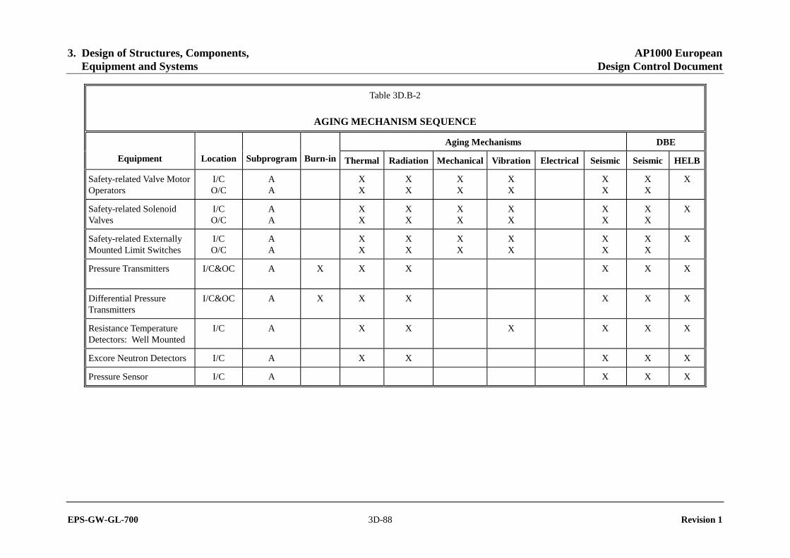
3. Design of Structures, Components, AP1000 European Equipment and Systems Design Control Document
EPS-GW-GL-700 3D-88 Revision 1
Table 3D.B-2
AGING MECHANISM SEQUENCE
Aging Mechanisms DBE
Equipment Location Subprogram Burn-in Thermal Radiation Mechanical Vibration Electrical Seismic Seismic HELB
Safety-related Valve Motor Operators
I/C O/C
A A
X X
X X
X X
X X
X X
X X
X
Safety-related Solenoid Valves
I/C O/C
A A
X X
X X
X X
X X
X X
X X
X
Safety-related Externally Mounted Limit Switches
I/C O/C
A A
X X
X X
X X
X X
X X
X X
X
Pressure Transmitters I/C&OC
A X X X X X X
Differential Pressure Transmitters
I/C&OC A X X X X X X
Resistance Temperature Detectors: Well Mounted
I/C A X X X X X X
Excore Neutron Detectors I/C A X X X X X
Pressure Sensor I/C A X X X

3. Design of Structures, Components, AP1000 European Equipment and Systems Design Control Document
EPS-GW-GL-700 3D-89 Revision 1
ATTACHMENT C
EFFECTS OF GAMMA RADIATION DOSES BELOW 104 RADS (100 GY) ON THE MECHANICAL PROPERTIES OF MATERIALS
C.1 Introduction
One potential common-mode failure mechanism to consider in the qualification of safety-related equipment is gamma radiation. As part of a qualification program, the effect of gamma radiation dose is considered for two purposes: as a component of the high-energy line break environment and as a potential aging mechanism that could reduce the capability of safety-related equipment to perform safety-related functions under design basis event conditions (seismic or high-energy line break).
The scope of this attachment is limited to consideration of the effect of radiation for that substantial portion of equipment that does not experience an adverse change in external environment as a result of a high-energy line break, and for which, therefore, the only gamma radiation concern is an in-service aging mechanism.
This attachment assumes that the equipment contains devices that have been selected for performance through the total integrated dose expected in service. For example, devices such as integrated circuits may have a limit of 1000 rads (10 Gy) established, in which case the following discussion applies for its installed life. The information in this attachment is not adequate to be applied to equipment that must perform its function in a high-energy line break.
The primary purpose of equipment qualification is to reduce the potential for common-cause failures due to environmental effects during the qualified life. Random failures that inevitably occur inservice are accommodated by the redundancy and diversity of the design of safety-related systems. Furthermore, in-service maintenance and testing programs are designed to detect such random failures. The chances of two identical components that perform identical functions failing during the same limited time period in between routine tests considered insignificant because of the following:
• General low failure rate of components used in nuclear equipment • Minor differences in component material or geometric tolerances or both • Minor differences in operating environment.
Therefore, failures that are induced in components by normal background gamma radiation below 104 rads (100 Gy) (103 rads, 10 Gy for some devices) alone are considered to be random. Thus, the only gamma radiation concern addressed for equipment not subject to an adverse high-energy line break environment is the potential for an aging mechanism resulting in a deterioration in component properties such that, when subject to seismic stress, a common-cause failure results. When considering such a failure mode, the aging mechanism of concern is not one that affects the electrical properties of components but one that reduces the mechanical strength and flexibility of components.

3. Design of Structures, Components, AP1000 European Equipment and Systems Design Control Document
EPS-GW-GL-700 3D-90 Revision 1
C.2 Scope
This report summarizes available information concerning the effects of gamma radiation on material mechanical properties. It justifies that for a gamma dose of less than 104 rads (100 Gy) there are no observable radiation effects that impact material mechanical properties. Of the materials investigated, only Teflon TFE is subject to an alteration of mechanical properties for a gamma dose of less than 105 rads (1000 Gy). Information is drawn from several sources listed as references in Section C.5. They include various texts concerning radiation effects and damage and pertinent reports.
C.3 Discussion
The primary effects of gamma photons on materials are ionization, material heating (primarily at high dose rates, which is of negligible significance here), and some displacement damage caused by high-energy photons. Some other types of radiation have effects similar to those induced by gamma radiation. This allows the use of data obtained from exposure of material to an alternate radiation to provide limited information concerning the effects of exposure to gamma radiation.
For example, the primary consequence of fast-neutron bombardment of material is atom displacement. Therefore, if the effect of radiation on a material property is primarily dependent on atom displacement, it is inferred that for an equivalent dose (rads, Gy) of gamma and fast-neutron radiation, data obtained from neutron irradiation provides a conservative estimate of the effect of gamma irradiation in producing displacements.
The same type of inference is drawn for the ionization effect of charged particle (for example, electron, proton, alpha particle) irradiation. Charged particles do not have the penetration capability that gamma or neutron radiations exhibit as a result of extensive interaction between charged particles and atomic charge centers.
Table 3D.C-1 summarizes information derived from the listed references. The information relates to the effect of gamma radiation on material mechanical properties. Table 3D.C-1 presents either the threshold dose (that dose at which an effect on any mechanical property can first be detected) or, the dose that results in the identified effect. This provides a general indication of the susceptibility of material mechanical properties to gamma radiation.
An evaluation of the information available on inorganic materials summarized in Table 3D.C-1 shows that the mechanical damage threshold for gamma radiation is many orders of magnitude greater than 104 rads (100 Gy). For the organic materials listed in Table 3D.C-1, a histogram comparing threshold dose level and frequency of material susceptibility is provided. In instances for which a material threshold dose is not indicated in Table 3D.C-1, a threshold value is assumed which is one order of magnitude lower than the indicated damage dose. Where information is available, referenced documents indicate that the difference between threshold dose and 25 percent damage dose is about a factor of three. Thus, a factor of 10 supplies substantial margin in estimating the threshold dose level. Figure C-1 shows that any indications of mechanical property damage thresholds below 104 rads (100 Gy) would be extremely unusual.
The references listed do not identify the existence of materials whose mechanical properties are deteriorated when exposed to a gamma radiation dose up to 104 rads (100 Gy). So it can be

3. Design of Structures, Components, AP1000 European Equipment and Systems Design Control Document
EPS-GW-GL-700 3D-91 Revision 1
concluded that common-cause failures do not occur in electrical equipment during or after a seismic event as a result of radiation-induced degradation up to 104 rads (100 Gy).
This is supported by NRC documentation available as an attachment to "Guidelines for Evaluating Environmental Qualification of Class 1E Electrical Equipment in Operating Reactors," which provides further justification for the use of 104 rads (100 Gy) as a threshold for mechanical damage. The NRC information appears to be consistent with the information provided in Table 3D.C-1.
C.4 Conclusions
For Class 1E equipment subject to a lifetime gamma dose of up to 104 rads (100 Gy), it is not necessary to address radiation aging for qualification purposes provided that the equipment is not required to perform a safety-related function in a high-energy line break environment.
As previously noted, this appendix does not apply to electrical properties of components in safety-related equipment.
C.5 References
1. Ricketts, L. W., "Fundamentals of Nuclear Hardening of Electronic Equipment," R. G. Krieger Publishing Co., 1986.
2. NASA Tech Brief Vol. 10, No. 5, Item #3, "Response of Dielectrics to Space Radiation," October 1986.
3. IRT Study 4331-006, "Design Guidelines for Transient Radiation Effects on Tactical Army Systems," Harry Diamond Labs, June 12, 1981.
4. Regulatory Guide 1.89, Rev. 1.
5. Hanks, C. L., and Hamman, D. J., "The Effect of Radiation on Electrical Insulating Materials," REIC Report No. 46, Radiation Effects Information Center, Battelle Memorial Institute, Columbus, Ohio, June 1969.
6. Kangilaski, M., "The Effects of Neutron Irradiation on Structural Materials," REIC Report No. 45, Radiation Effects Information Center, Battelle Memorial Institute, Columbus, Ohio, June 1967.
7. Hanks, C. L., and Hamman, D. J., "The Effect of Nuclear Radiation on Capacitors," REIC Report No. 44, Radiation Effects Information Center, Battelle Memorial Institute, Columbus, Ohio, December 1966.
8. Chapin, W. E., Drennan, J. E., and Hamman, D. J., "The Effect of Nuclear Radiation on Transducers," REIC Report No. 43, Radiation Effects Information Center, Battelle Memorial Institute, Columbus, Ohio, October 1966.

3. Design of Structures, Components, AP1000 European Equipment and Systems Design Control Document
EPS-GW-GL-700 3D-92 Revision 1
9. Drennan, J. E., and Hamman, D. J., "Space Radiation Damage to Electronic Components and Materials," REIC Report No. 39, Radiation Effects Information Center, Battelle Memorial Institute, Columbus, Ohio, January 1966.
10. Larin, F., "Radiation Effects in Semiconductor Devices," John Wiley and Sons, New York, 1968.
11. Billington, D. S., and Crawford, J. H., "Radiation Damage in Solids," Princeton University Press, Princeton, New Jersey, 1961.
12. Corbett, J. W., "Electron Radiation Damage in Semiconductors and Metals," Academic Press, New York, 1966.
13. Ricketts, L. W., "Fundamentals of Nuclear Hardening of Electronic Equipment," Wiley-Interscience, New York, 1972.
14. Kircher, J. F., and Bowman, Richard E., "Effect of Radiation on Materials and Components," Reinhold Publishing Corp., New York, 1964.
15. Bolt, R. O., and Carroll, J. G., "Radiation Effects on Organic Materials," Academic Press, New York, 1963.
16. Kaplan, Irvin, "Nuclear Physics," Addison-Wesley, 1962.

3. Design of Structures, Components, AP1000 European Equipment and Systems Design Control Document
EPS-GW-GL-700 3D-93 Revision 1
Table 3D.C-1 (Sheet 1 of 2)
RADIATION-INDUCED DEGRADATION OF MATERIAL MECHANICAL PROPERTIES
Material Mechanical Damage Threshold Dose for Comments
Structural Metals 1019 n/cm2 (fast neutron spectrum) Similar to cold work (1010 rads, 108 Gy)
Inorganic Materials ~1017 n/cm2 (fast neutron spectrum) Borated materials have lower threshold values for neutron irradiation.
Elastomers
Natural Rubber 2x10⁶ rads(C) (2x10⁴ Gy)
Polyurethane Rubber 9x10⁵ rads(C) (9x10³ Gy)
Styrene-Butadiene Rubber 2x10⁶ rads(C) (2x10⁴ Gy)
Nitrile Rubber 7x10⁶ rads(C) (7x10⁴ Gy) Compression set is 25% degraded
Neoprene Rubber 7x10⁶ rads(C) (7x10⁴ Gy)
Hypalon ~107 rads(C) (~105 Gy) Variable
Acrylic Rubber 9x10⁷ rads(C) (9x10⁵ Gy) Variable
Silicone Rubber 107 rads(C) (105 Gy) ~25% damage
Fluorocarbon Rubber 9x10⁷ rads(C) (9x10⁵ Gy) ~25% hardness, 80% elongation
Polysulfate Rubber 108 rads(C) (106 Gy)
Butyl Rubber 107 rads(C) (105 Gy) ~25% damage
One rad (Gy) (C) is the field of radiation that will produce 100 ergs/gm (0.01 J/kg) in carbon.
Plastic
Teflon TFE 1.7x10⁴ rads(C) (1.7x10² Gy)
Kel-F 1.3x10⁶ rads(C) (1.3x10⁴ Gy)
Polyethylene ≥ 107 rads(C) (≥ 105 Gy)
Polystyrene 108 rads (106 Gy)
Mylar 106 rads(C) (104 Gy) Conservative
Polyamide (Nylon) 8.6x10⁵ rads(C) (8.6x10³ Gy)
Diallyl Phthalate 108 rads(C) (106 Gy)
Polypropylene 107 rads(C) (105 Gy)
Polyurethane 7x10⁸ rads(C) (7x10⁶ Gy)
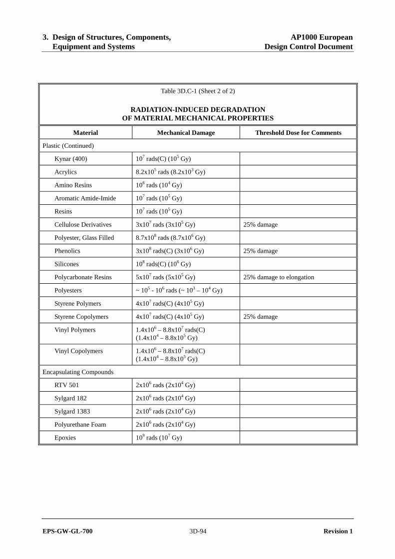
3. Design of Structures, Components, AP1000 European Equipment and Systems Design Control Document
EPS-GW-GL-700 3D-94 Revision 1
Table 3D.C-1 (Sheet 2 of 2)
RADIATION-INDUCED DEGRADATION OF MATERIAL MECHANICAL PROPERTIES
Material Mechanical Damage Threshold Dose for Comments
Plastic (Continued)
Kynar (400) 107 rads(C) (105 Gy)
Acrylics 8.2x10⁵ rads (8.2x10³ Gy)
Amino Resins 106 rads (104 Gy)
Aromatic Amide-Imide 107 rads (105 Gy)
Resins 107 rads (105 Gy)
Cellulose Derivatives 3x10⁷ rads (3x10⁵ Gy) 25% damage
Polyester, Glass Filled 8.7x10⁸ rads (8.7x10⁶ Gy)
Phenolics 3x10⁸ rads(C) (3x10⁶ Gy) 25% damage
Silicones 108 rads(C) (106 Gy)
Polycarbonate Resins 5x10⁷ rads (5x10⁵ Gy) 25% damage to elongation
Polyesters ~ 105 - 106 rads (~ 103 – 104 Gy)
Styrene Polymers 4x10⁷ rads(C) (4x10⁵ Gy)
Styrene Copolymers 4x10⁷ rads(C) (4x10⁵ Gy) 25% damage
Vinyl Polymers 1.4x10⁶ – 8.8x10⁷ rads(C) (1.4x10⁴ – 8.8x10⁵ Gy)
Vinyl Copolymers 1.4x10⁶ – 8.8x10⁷ rads(C) (1.4x10⁴ – 8.8x10⁵ Gy)
Encapsulating Compounds
RTV 501 2x10⁶ rads (2x10⁴ Gy)
Sylgard 182 2x10⁶ rads (2x10⁴ Gy)
Sylgard 1383 2x10⁶ rads (2x10⁴ Gy)
Polyurethane Foam 2x10⁶ rads (2x10⁴ Gy)
Epoxies 109 rads (107 Gy)

3. Design of Structures, Components, AP1000 European Equipment and Systems Design Control Document
EPS-GW-GL-700 3D-95 Revision 1
Figure 3D.C-1
Histogram of Threshold Gamma Dose for Mechanical Damage to Elastomers, Plastics, and Encapsulation Compounds
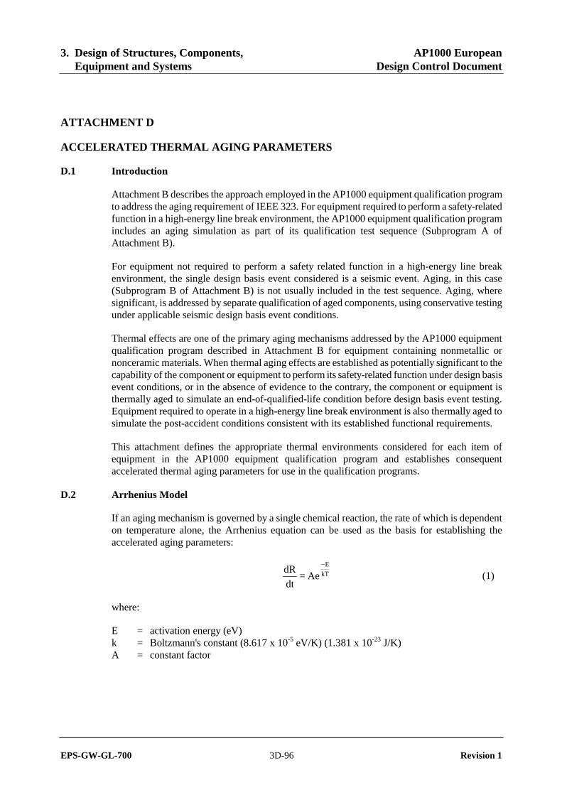
3. Design of Structures, Components, AP1000 European Equipment and Systems Design Control Document
EPS-GW-GL-700 3D-96 Revision 1
ATTACHMENT D
ACCELERATED THERMAL AGING PARAMETERS
D.1 Introduction
Attachment B describes the approach employed in the AP1000 equipment qualification program to address the aging requirement of IEEE 323. For equipment required to perform a safety-related function in a high-energy line break environment, the AP1000 equipment qualification program includes an aging simulation as part of its qualification test sequence (Subprogram A of Attachment B).
For equipment not required to perform a safety related function in a high-energy line break environment, the single design basis event considered is a seismic event. Aging, in this case (Subprogram B of Attachment B) is not usually included in the test sequence. Aging, where significant, is addressed by separate qualification of aged components, using conservative testing under applicable seismic design basis event conditions.
Thermal effects are one of the primary aging mechanisms addressed by the AP1000 equipment qualification program described in Attachment B for equipment containing nonmetallic or nonceramic materials. When thermal aging effects are established as potentially significant to the capability of the component or equipment to perform its safety-related function under design basis event conditions, or in the absence of evidence to the contrary, the component or equipment is thermally aged to simulate an end-of-qualified-life condition before design basis event testing. Equipment required to operate in a high-energy line break environment is also thermally aged to simulate the post-accident conditions consistent with its established functional requirements.
This attachment defines the appropriate thermal environments considered for each item of equipment in the AP1000 equipment qualification program and establishes consequent accelerated thermal aging parameters for use in the qualification programs.
D.2 Arrhenius Model
If an aging mechanism is governed by a single chemical reaction, the rate of which is dependent on temperature alone, the Arrhenius equation can be used as the basis for establishing the accelerated aging parameters:
kT
E
Ae = dt
dR−
(1)
where:
E = activation energy (eV) k = Boltzmann's constant (8.617 x 10⁻⁵ eV/K) (1.381 x 10⁻²³ J/K) A = constant factor
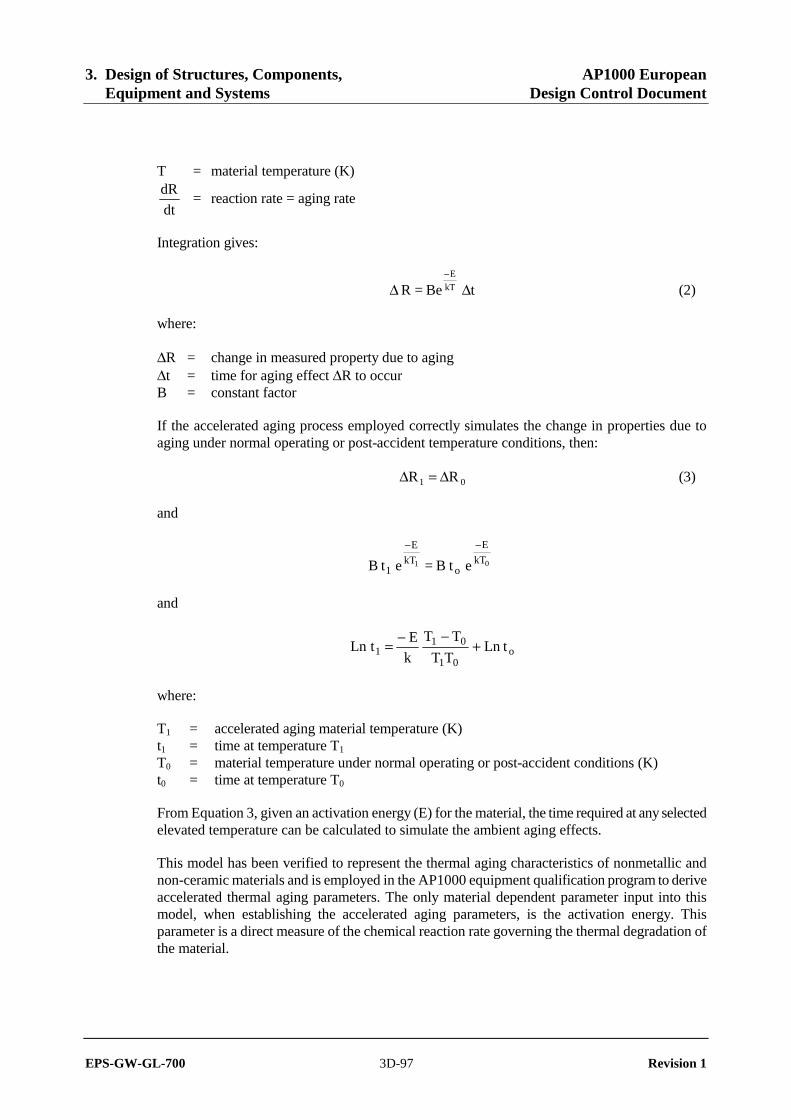
3. Design of Structures, Components, AP1000 European Equipment and Systems Design Control Document
EPS-GW-GL-700 3D-97 Revision 1
T = material temperature (K)
dt
dR = reaction rate = aging rate
Integration gives:
t Be = R kT
E
ΔΔ−
(2)
where:
ΔR = change in measured property due to aging Δt = time for aging effect ΔR to occur B = constant factor
If the accelerated aging process employed correctly simulates the change in properties due to aging under normal operating or post-accident temperature conditions, then:
01 RR Δ=Δ (3)
and
etB = et B 01 kT
E
okT
E
1
−−
and
o01
011 tLn
TT
TT
k
EtLn +
−−=
where:
T1 = accelerated aging material temperature (K) t1 = time at temperature T1 T0 = material temperature under normal operating or post-accident conditions (K) t0 = time at temperature T0
From Equation 3, given an activation energy (E) for the material, the time required at any selected elevated temperature can be calculated to simulate the ambient aging effects.
This model has been verified to represent the thermal aging characteristics of nonmetallic and non-ceramic materials and is employed in the AP1000 equipment qualification program to derive accelerated thermal aging parameters. The only material dependent parameter input into this model, when establishing the accelerated aging parameters, is the activation energy. This parameter is a direct measure of the chemical reaction rate governing the thermal degradation of the material.
3. Design of Structures, Components, AP1000 European Equipment and Systems Design Control Document
EPS-GW-GL-700 3D-98 Revision 1
D.3 Activation Energy
A single material may have more than one physical property that thermally degrades (for example, dielectric strength, flexural strength.) As a consequence, the material exhibits different activation energies with respect to each property. The activation energy selected is the one that reflects the physical property most significant to the safety-related function performed or the stresses applied to the material by the design basis fault(s) considered.
In actual practice, however, rarely is the choice so simple. Electrical components are invariably made up of more than one material. In many cases either the materials employed are not known in any chemical detail but just by a general organic or industrial trade name, or the appropriate activation energy is not known.
Where an activation energy is not available that reflects the material or component as well as the physical property of interest, a single conservative activation energy is used.
A distribution of activation energies (Figure 3D.D-1) was produced by EPRI (Reference 1) based on 170 materials. An independent review of materials used in Westinghouse-supplied equipment is summarized in Table 3D.D-1 and plotted in similar form in Figure 3D.D-2. A statistical analysis indicates that 95 percent of the activation energies exceed about 0.4 eV (6.409 E-20J) from the EPRI data and 0.6 eV (9.613 E-20J) from the Westinghouse data. Based on this information, a value of 0.5 eV (8.011 E-20J) is selected for use throughout this program whenever specific activation energies are not available. Employing a low value of activation energy in deriving the accelerated aging parameters causes materials having a high activation energy to be overaged with respect to the simulated conditions.
D.4 Thermal Aging (Normal/Abnormal Operating Conditions)
This section establishes the methodology employed and derives a typical set of accelerated aging parameters for equipment in various plant locations.
D.4.1 Normal Operation Temperature (T0)
In determining the ambient operating temperature (T0) of the component/material/equipment under investigation, the following is considered:
• External ambient temperature (Ta) • Temperature rise in cabinet/enclosure (Tr) • Self-heating effects (Tj)
where To = Ta + Tr + Tj
D.4.1.1 External Ambient Temperature (Ta)
a) For equipment located in areas supplied by an air-conditioning system, a typical value assumed for (Ta) throughout the qualified life is 68°F (20°C). For air-conditioning systems, two excursions per year to 91°F (33.3°C), each lasting 72 hours, has a negligible additional aging effect.

3. Design of Structures, Components, AP1000 European Equipment and Systems Design Control Document
EPS-GW-GL-700 3D-99 Revision 1
b) For equipment located in areas supplied by a ventilation system, a typical value assumed (Ta) throughout the qualified life is 77°F (25°C). Two excursions per year to 122°F (50°C), each lasting 72 hours, has a negligible additional aging effect.
D.4.1.2 Temperature Rise in Enclosure (Tr)
This temperature rise is estimated based on the heat generated (radiative and conductive) by equipment inside or attached to the enclosure. For example, limit switches may be affected by process heat through the valve. Temperatures measured during test runs may be available. A typical value for temperature rise inside an electronics cabinet is 10°C.
D.4.1.3 Self-Heating Effects (Tj)
For equipment that is energized during most of its life, a self-heating effect is measured or established. If the equipment is energized only for short durations, this effect may be determined to be negligible. Temperature effects due to the solenoid of an energized valve may be significant (over 40°C). In determining junction temperatures of semiconductor devices, known operating parameters along with the thermal impedance are used. If the power dissipation is not known, a 50 percent operating stress is assumed.
D.4.2 Accelerated Aging Temperature (Ti)
Temperatures used for actual accelerated thermal aging tests are determined based on the equipment or component specifications in an attempt to prevent damage from high temperature alone and second-order (non-Arrhenius) effects such as the glass transition temperature of plastics. A maximum of 130°C is typically used for electronic component aging, but this is evaluated on a case basis. If the device is energized during the accelerated aging process, the self-heating effect as determined in the preceding section is added to the oven temperature to determine the total aging temperature (Ti).
D.4.3 Examples of Arrhenius Calculations
D.4.3.1 For a Normally Energized Component Aged Energized – The Self-Heating Effect is Added to Both (To) and (Ti):
Conditions: Ta = 25°C, Tr = 10°C Tj = 25°C, eV = 0.5 (8.011 E-20J), Aging time = ti Oven temperature = 130°C Qualified life goal = 10 years
Therefore To = 25 + 10 + 25 = 60°C = 333K Ti = 130 + 25 + 155°C = 428K
t1 = 10e )333428(
)333428(
K
5.0
×−−
= 1831 hours

3. Design of Structures, Components, AP1000 European Equipment and Systems Design Control Document
EPS-GW-GL-700 3D-100 Revision 1
D.4.3.2 For a Normally De-energized Component Aged Energized – the Self-heating Effect is Added Only to Ti:
Conditions: Ta = 25°C, Tr = 10°C Tj = 25°C, eV = 0.5 (8.011 E-20J), Aging time = t1 Oven temperature = 130°C Qualified life goal = 10 years
Therefore To = 25 + 10 = 35°C = 308K Ti = 130 + 25 + 155°C = 428K
t1 = 10e )308428(
)308428(
K
5.0
×−−
= 445 hours
D.5 Post-Accident Thermal Aging
Most cases, some safety-related postaccident performance capability is specified by the functional requirements. As a consequence, to qualify equipment to IEEE 323, the effects of post-accident thermal aging must be simulated after the high-energy line break test. This section establishes the accelerated thermal aging parameters employed in performing this simulation.
D.5.1 Post-Accident Operating Temperatures
Assuming continuous operation of containment safeguards systems following an accident, the containment environment temperature is reduced to the external ambient temperature well within one year for any postulated high-energy line break. However, to allow for possible variations in plant operations following an accident, the limiting design high-energy line break envelope is assumed to remain constant at 155°F (68°C) between four months and one year. As indicated in Figure 3D.D-3, the limiting design profile post-accident is defined by the LOCA envelope (Figure 3D.5-6) starting at one day.
For safety-related equipment located inside containment, either the self-heating effects of the operating unit, under post-accident conditions, may be insignificant compared to the heat input from the external environment (transmitters, RTDs), or the unit may not be in continuous operation during this phase (valve operators). So it may not be necessary to add a specific temperature increment to account for self-heating of these devices following an accident. The profile reproduced here as Figure 3D.D-3 is then input at T0 into the Arrhenius equation to calculate appropriate accelerated aging parameters for post-accident conditions. However, as noted in Section D.4, if the equipment is energized during the aging simulation period, the self-heating effect is added to both To and Ti.
D.5.2 Accelerated Thermal Aging Parameters for Post-Accident Conditions
The aging temperature most often used for post-accident simulation is 250°F (121°C). This temperature is selected as a maximum for electronic components and is generally used for tests. Using this value and the conservative activation energy of 0.5 eV (8.011 E-20J), the Arrhenius equation is applied to the curve in Figure 3D.D-3 from one day to four months or to one year in
3. Design of Structures, Components, AP1000 European Equipment and Systems Design Control Document
EPS-GW-GL-700 3D-101 Revision 1
small increments of time. The required aging times to simulate these small increments are then summed to yield a total test time of 42 days to simulate four months and about 67 days to simulate one year post-accident operation. Including appropriate margin adds four and seven days respectively to the total test time.
If an activation energy of 0.8 eV (1.282 E-19J) is justified, the Arrhenius equation yields 19 days to simulate four months and 26 days to simulate one year with two days and three days margin to be included in the total test time.
D.6 References
1. EPRI NP-1558, Project 890-1, "A Review of Equipment Aging Theory and Technology," September 1980.

3. Design of Structures, Components, AP1000 European Equipment and Systems Design Control Document
EPS-GW-GL-700 3D-102 Revision 1
Table 3D.D-1 (Sheet 1 of 2)
ACTIVATION ENERGIES FROM WESTINGHOUSE REPORTS
Material Electron
Volts
Melamine-Glass, G5 0.29
Epoxy B-725 0.48
Ester-Glass, GPO-3 0.57
RTV Silicone 0.60
Phenolic-Asbestos, A 0.61
Nylon 33 GF 0.70
Acetal 0.73
Mineral Phenolic 0.74
Silicone Varnish 0.74
Polypropylene 0.81
Polysulfone 0.83
Phenolic-Cotton, C 0.84
Formvar 0.85
Epoxy 0.88
Epoxy Adhesive 0.89
Nylon 0.90
Pressboard 0.91
Kapton 0.93
Silicone 0.94
Phenolic-Asbestos, A 0.94
Cast Epoxy 0.98
Urethane-Nylon 0.99
Phenolic-Glass, G-3 1.01
Polycarbonate 1.01
Phenolic-Paper, X 1.02
Epoxy Wire 1.05
Epoxy-Glass, FR-4 1.05
Varnish Cotton 1.06
PVC 1.08
Ester-Glass, GPO-1 1.09
Cellulose Phenolic 1.10
X-Link Ethylene 1.11
Urethane 1.12
Ester-Glass, GPO-2 1.13
Ester-Nylon 1.14
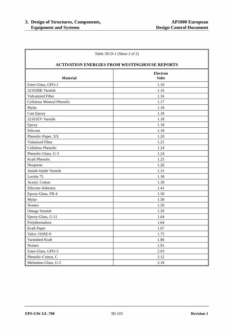
3. Design of Structures, Components, AP1000 European Equipment and Systems Design Control Document
EPS-GW-GL-700 3D-103 Revision 1
Table 3D.D-1 (Sheet 2 of 2)
ACTIVATION ENERGIES FROM WESTINGHOUSE REPORTS
Material Electron
Volts
Ester-Glass, GPO-1 1.16
32102BK Varnish 1.16
Vulcanized Fiber 1.16
Cellulose Mineral Phenolic 1.17
Mylar 1.18
Cast Epoxy 1.18
32101EV Varnish 1.18
Epoxy 1.18
Silicone 1.18
Phenolic-Paper, XX 1.20
Vulanized Fiber 1.21
Cellulose Phenolic 1.24
Phenolic-Glass, G-3 1.24
Kraft Phenolic 1.25
Neoprene 1.26
Amide-Imide Varnish 1.31
Loctite 75 1.38
Acetyl. Cotton 1.39
Silicone-Asbestos 1.41
Epoxy-Glass, FR-4 1.50
Mylar 1.58
Nomex 1.59
Omega Varnish 1.59
Epoxy-Glass, G-11 1.64
Polythermaleze 1.64
Kraft Paper 1.67
Valox 310SE-0 1.75
Varnished Kraft 1.86
Nomex 1.91
Ester-Glass, GPO-3 2.03
Phenolic-Cotton, C 2.12
Melamine-Glass, G-5 2.18

3. Design of Structures, Components, AP1000 European Equipment and Systems Design Control Document
EPS-GW-GL-700 3D-104 Revision 1
Figure 3D.D-1
Frequency Distribution of Activation Energies of Various Components/Materials (EPRI Data)

3. Design of Structures, Components, AP1000 European Equipment and Systems Design Control Document
EPS-GW-GL-700 3D-105 Revision 1
Figure 3D.D-2
Frequency Distribution of Activation Energies of Various Components/Materials (Westinghouse Data)

3. Design of Structures, Components, AP1000 European Equipment and Systems Design Control Document
EPS-GW-GL-700 3D-106 Revision 1
Figure 3D.D-3
Post-Accident Temperature Profile

3. Design of Structures, Components, AP1000 European Equipment and Systems Design Control Document
EPS-GW-GL-700 3D-107 Revision 1
ATTACHMENT E
SEISMIC QUALIFICATION TECHNIQUES
E.1 Purpose
The following is the methodology used to seismically qualify seismic Category I mechanical and electrical equipment for the AP1000 equipment qualification program. Qualification work covered by this appendix meets the applicable requirements of IEEE 344-1987 and 382-1996.
E.2 Definitions
The following are definitions of terms unique to or distinct from common industry usage. (See Section E.4.2.)
E.2.1 1/2 Safe Shutdown Earthquake
The 1/2 safe shutdown earth (SSE) is the earthquake level used during seismic testing to seismically age safety-related equipment before performing safe shutdown earthquake testing.
E.2.2 Seismic Category I Equipment
Seismic Category 1 equipment consists of structures, systems, and components required to withstand the effects of the safe shutdown earthquake and remain structurally intact, leak-tight (in case of pressurized systems), and functional to the extent required to perform their safety-related function.
E.2.3 Seismic Category II Equipment
Seismic Category II equipment is that equipment whose continued function is not required, but whose failure could reduce the functioning of seismic Category I structures, systems, and components to an unacceptable level. Seismic Category II equipment must be capable of maintaining structural integrity so that a seismic event up to and including an SSE would not cause such a failure.
E.2.4 Non-seismic Equipment
Equipment designated as non-seismic does not require seismic qualification.
E.2.5 Active Equipment Equipment that must perform a mechanical or electrical operation during or after (or both) the safe shutdown earthquake in order to accomplish its safety-related function.
E.2.6 Passive Equipment Equipment where maintenance of structural or pressure integrity is the only requirement necessary for accomplishing its safety-related function.

3. Design of Structures, Components, AP1000 European Equipment and Systems Design Control Document
EPS-GW-GL-700 3D-108 Revision 1
E.3 Qualification Methods
This section presents a general description of the seismic qualification methods used by AP1000 for the seismic qualification of seismic Category I safety-related mechanical and electrical equipment. Three methods are used: test, analysis, and a combination of the two. The approaches for qualification by testing and by analysis are discussed in Section E.5 and Section E.6, respectively. The following discussion covers the conditions under which each approach is used and the general requirements applicable to the use of the methods. The qualification sequence is defined in Appendix 3D.
E.3.1 Use of Qualification by Testing
The preferred method for seismic qualification of safety-related Class 1E electrical and electromechanical equipment is seismic testing. The nature of the seismic and vibrational input used depends on where the equipment is used. For equipment mounted so that the seismic environment includes frequency content between 1 and 33 hertz (hard mounted), the seismic test input is multifrequency. For equipment mounted so that seismic ground motion is filtered to contain one predominant structural mode (line mounted), single frequency testing is appropriate. This is the case for equipment mounted on piping systems, ductwork, or cable trays.
E.3.2 Use of Qualification by Analysis
Analysis is used for seismic qualification when one of the following conditions is met:
• The equipment is too large or the interface support conditions cannot adequately be simulated on the test table.
• The only requirement is to maintain structural integrity during a postulated seismic event.
• The equipment represents a linear system, or the nonlinearities can conservatively be accounted for in the analysis. This approach is also applicable to the development of the seismic environment, required response spectrum curve, at the mounting location of a component attached to a larger structure when the device is seismically qualified by separate component testing.
• The analysis is used to document the seismic similarity of the equipment provided and that previously qualified by testing.
Seismic qualification of safety-related electrical equipment by analysis alone is not recommended for complex equipment that cannot be modeled to adequately predict its response. Analysis without testing may be acceptable provided structural integrity alone can ensure the design-intended function.

3. Design of Structures, Components, AP1000 European Equipment and Systems Design Control Document
EPS-GW-GL-700 3D-109 Revision 1
E.4 Requirements
E.4.1 Damping
Damping level of a component or system describes its capability to dissipate vibrational energy during a seismic event. The damping level used defines the response magnitude of an ideal single degree of freedom linear oscillator when subjected to the specified input as documented by the required response spectrum (RRS) curve. The significance of the damping value used depends on whether qualification is by testing or analysis.
E.4.1.1 Testing
Equipment qualification by testing involves subjecting the base of the equipment to a representative seismic acceleration time history. The response characteristics of the equipment are a function of the inherent damping present in the equipment. In this case the damping value used (typically five percent) serves as a convenient means of showing the compliance of the test response spectrum (TRS) with the required response spectrum.
E.4.1.2 Analysis
In the case of qualification by analysis, the damping level used is representative of the damping actually present in the equipment. Unless other documented equipment damping data is available, the values specified in Table 3.7.1-1 of Chapter 3 are used.
E.4.2 Interface Requirements
As part of the seismic qualification program, consideration is given to the definition of the clearances needed around the equipment mounted in the plant to permit the equipment to move during a postulated seismic event without causing impact between adjacent pieces of safety-related equipment. This is done as part of seismic testing by measuring the maximum dynamic relative displacement of the top and bottom of the equipment.
When performing qualification by analysis, the relative motion is obtained as part of the analytical results. These motions are reported in the qualification report and are used to determine the required clearance between adjacent pieces of equipment.
In addition, the qualification program takes into account the restraining effect of other interfaces, such as cables and conduits attached to the equipment, which may change the dynamic response characteristic of the equipment.
E.4.3 Mounting Simulation
The mounting conditions simulated by analysis or during seismic test are representative of the equipment as-installed mounting conditions used for the AP1000 equipment. When an interfacing structure exists between the safety-related equipment being qualified and the floor or wall at which the equipment mounting required response spectrum is specified, its flexibility is simulated as part of the qualification program. If this is not done, justification must be provided,

3. Design of Structures, Components, AP1000 European Equipment and Systems Design Control Document
EPS-GW-GL-700 3D-110 Revision 1
demonstrating that the deviations in mounting conditions do not affect the applicability of qualification program.
E.4.4 1/2 Safe Shutdown Earthquake
The AP1000 makes use of a small earthquake having the intensity of one-half of the safe shutdown earthquake at the safety-related equipment mounting location to simulate the fatigue effects of smaller earthquakes that may occur before the postulated safe shutdown earthquake. These small earthquakes correspond to the operating basis earthquakes (OBEs) referenced in IEEE 344-1987. When qualification by testing is used, five of these small earthquakes are used to vibrationally age the equipment before the safe shutdown earthquake. When qualification by analysis is used, two safe shutdown earthquake events are used to simulate the fatigue aging effects. Each event contains 10 peak cycles. These stress cycles are used to verify that the equipment is not subject to failure due to low cycle fatigue.
E.4.5 Safe Shutdown Earthquake
The safe shutdown earthquake required response spectrum curve defines the seismic qualification basis for each piece of safety-related equipment. The seismic level varies according to the mounting location of the equipment. When equipment qualification is based on testing, an additional 10 percent test acceleration margin is added as specified in IEEE 323-1974.
E.4.6 Other Dynamic Loads
Hydrodynamic loads are considered as part of the qualification program, where applicable.
E.5 Qualification by Test
Seismic qualification testing is the preferred method for electrical, mechanical, and electromechanical equipment. Seismic testing shall be performed and input generated as specified in IEEE 344-1987. The nature of the test input used depends on whether the equipment is hard mounted or line mounted. The test program consists of the following elements, as applicable: environmental aging, mechanical aging, vibrational aging, and safe shutdown earthquake testing. For those cases where the equipment is also subject to a loss of coolant or a high-energy line break accident, these accidents are simulated on the same qualification specimen after completion of the testing previously discussed. (See Sections 3D.4.4 and 3D.7.4.)
The characteristics of the required seismic and dynamic input motions should be specified by the response spectrum or time history methods. These characteristics, derived from the structures or systems seismic and dynamic analyses, should be representative of the input motions at the equipment mounting locations.
For seismic and dynamic loads, the actual test input motion should be characterized in the same manner as the required input motion, and the conservatism in amplitude and frequency content should be demonstrated (that is, the test response spectrum should closely resemble and envelop the required response spectrum over the critical frequency range).

3. Design of Structures, Components, AP1000 European Equipment and Systems Design Control Document
EPS-GW-GL-700 3D-111 Revision 1
Since seismic and the dynamic load excitation generally have a broad frequency content, multi-frequency vibration input motion should be used. However, single frequency input motion, such as sine beats, is acceptable provided the characteristics of the required input motion indicate that the motion is dominated by one frequency (for example, by structural filtering effects), or that the anticipated response of the equipment is adequately represented by one mode, or in the case of structural integrity assurance, that the input has sufficient intensity and duration to produce sufficiently high levels of stress for such assurance. Components that have been previously tested to IEEE-344-1971 should be reevaluated or retested to justify the appropriateness of the input motion used, and requalified if necessary.
For the seismic and dynamic portion of the loads, the test input motion should be applied to one vertical axis and one principal axis (or two orthogonal axes) simultaneously unless it can be demonstrated that the equipment response motion in the horizontal direction is not sensitive to the vibratory motion in the horizontal direction, and vice versa. The time phasing of the inputs in the vertical and horizontal directions must be such that a purely rectilinear resultant input is avoided. An acceptable alternative is to test with vertical and horizontal inputs in-phase, and then repeat the test with inputs 180 degrees out-of-phase. In addition, the test must be repeated with the equipment rotated 90 degrees horizontally.
E.5.1 Qualification of Hard-Mounted Equipment
Hard-mounted equipment is seismically tested mounted on a test table capable of producing multifrequency, multiaxis inputs. The waveform characteristics of the input are random and scaled in such a way that the test response spectrum equals or exceeds the required response spectrum (including margin). The input signal meets the requirements of Section 7.6.3 of IEEE 344-1987.
Furthermore, the test input simulates the multidirectional nature of the earthquake. The preferred method for meeting this requirement is to the use a triaxial test table capable of producing three statistically independent, orthogonal input motions. In this case the seismic testing consists of five 1/2 safe shutdown earthquake tests and one safe shutdown earthquake test in one orientation.
Using a biaxial test table is acceptable if it is justified that the horizontal and vertical test inputs conservatively simulate the three-dimensional nature of the seismic event. One acceptable approach is to mount the equipment on the test table with its front-to-back axis oriented at 45 degrees to the horizontal drive axis and scale the horizontal component of the input by a factor of the square root of two. Statistically independent inputs are preferred and, if used, the test can be performed in two stages, with the equipment rotated 90 degrees about the vertical axis. In this case, the five 1/2 safe shutdown earthquake inputs need to be applied only in the first orientation.
If a dependent biaxial test table is used, the test is performed in four stages. The first stage involves five 1/2 safe shutdown earthquake tests and one safe shutdown earthquake test in the first orientation. The second, third, and fourth orientations are obtained by successively rotating the equipment 90 degrees clockwise from its previous position. One safe shutdown earthquake test is performed in each of the last three orientations.
Each multifrequency test has a minimum of 15 seconds of strong motion input. The strong motion portion is preceded and followed by a period of testing where the test input is ramped up and ramped down, respectively, so that the equipment is not subjected to impact loading. The

3. Design of Structures, Components, AP1000 European Equipment and Systems Design Control Document
EPS-GW-GL-700 3D-112 Revision 1
adequacy of each test run is evaluated using the criteria set forth in Section 7.6.3.1 of IEEE 344-1987.
E.5.2 Qualification of Line-Mounted Equipment
Line-mounted equipment, because of the dynamic filtering characteristics of its mounting, is effectively subject to single frequency input. This condition is common for valves and sensors supported by piping systems, cable trays, and duct systems. This equipment is qualified consistent with the requirements of IEEE 382-1996. In some cases this equipment may also be used in the hard-mounted condition. In this case multifrequency, multiaxis testing is also required unless justification is provided that the previous single frequency tests demonstrate the capability of the equipment to operate under the hard-mounted seismic conditions. Because of the large size of typical valves, it may be necessary to perform separate testing of the operators and valve assembly.
E.5.2.1 Seismic Qualification Test Sequence
The seismic qualification process is broken down into the following steps:
1. Mount the equipment on a rigid test fixture and perform a resonant search test to demonstrate that the equipment is structurally rigid (fundamental frequency greater than 33 hertz) and does not amplify the seismic motions acting at the equipment mounting interface.
2. Perform single frequency testing on the line-mounted equipment.
3. Perform multifrequency, multiaxis testing on the equipment, if appropriate.
4. If an active valve assembly is to be seismically qualified, additional testing is needed as follows:
a. Perform a static pull test on the valve.
b. Perform a static seismic analysis using a verified model of the valve and its extended structure to demonstrate that the valve has adequate structural strength to perform its safety-related function without exceeding the design allowable stresses specified in ASME Code, Section III, Subsection NB, NC, or ND for pressure-retaining parts, as appropriate, and Subsection NF for non-pressure-retaining boundary parts. Limiting extended structure stress to material yield strength minimizes deflections, which could interfere with valve stroke function.
E.5.2.2 Line Vibration Aging
Line-mounted equipment may be subject to operational vibrations resulting from normal plant operations. The potential fatiguing effect of this vibrational aging is simulated as part of the qualification program. This requirement is satisfied by subjecting the equipment to a sine sweep from 5 to 100 to 5 hertz at an acceleration level of 0.75g or such reduced acceleration at low
3. Design of Structures, Components, AP1000 European Equipment and Systems Design Control Document
EPS-GW-GL-700 3D-113 Revision 1
frequencies to limit the double amplitude to 0.025 inch (0.635 millimeter) as specified in Section 5.3.a, Part III of IEEE 382-1996.
E.5.2.3 Single Frequency Testing
The single frequency testing acceleration waveform is either sine beat or sine dwell applied at one-third octave frequency intervals as specified in IEEE 382-1996. Each dwell has a time length adequate to permit performance of functional testing, with a minimum time of 15 seconds. To account for the three-dimensional nature of the seismic event, the test input level is taken as the square root of two times the required input motion (RIM) level specified in IEEE 382. The level includes the 10 percent test margin. Each test series is performed using single axis input. The test series is performed successively in each of three orthogonal axes.
E.5.2.4 Seismic Aging
The aging effect of the five 1/2 safe shutdown earthquake earthquakes can be simulated by exposing the equipment to two sinusoidal sweeps at one-half of the safe shutdown earthquake required input motion level in each orthogonal axis. Each sweep shall go from 2 to 35 hertz to 2 hertz at a rate not to exceed one octave per minute. One sweep is performed with the equipment in its inactive mode, and the other with the equipment in its safety-related operational mode.
E.5.2.5 Static Deflection Testing of Active Valves The seismic testing just discussed is normally performed only on the valve operator and the attached appurtenances. If the valve assembly is rigid, the operability of the valve assembly during a postulated seismic event may be demonstrated by performing a static pull test using a peak acceleration value equivalent to a triaxial acceleration of 6g. If the valve assembly is determined to be flexible, a supplemental analysis of the seismic response of the flexible valve and its supporting piping is performed to determine the actual acceleration level present at the center of gravity of the valve assembly.
The valve is placed in a suitable test fixture with the operator and appurtenances mounted and oriented as in the normal valve assembly installation. The valve is mounted so that the extended structure is freestanding and supported only by the valve nozzles. The valve is positioned so that the horizontal and vertical load components simulating the three-dimensional nature of the seismic event produce a worst-case stress condition in the valve extended structure.
During testing, the valve shall be internally pressurized and nozzle loads applied. Static loads simulating dead weight and seismic loads are applied to the extended structure. The tests are normally performed at ambient temperature. These loads simulate to the extent feasible the load distribution acting on critical parts of the valve assembly. The valve is actuated using the actuator system seismically qualified according to IEEE 382-1996. The valve assembly is cycled from its normal to the desired safety-related position within the time limits defined in the equipment specification. Leakage measurements are made, where required, and compared to the allowable values specified in the valve design specification.

3. Design of Structures, Components, AP1000 European Equipment and Systems Design Control Document
EPS-GW-GL-700 3D-114 Revision 1
E.5.3 Operational Conditions
When equipment being qualified performs a safety-related function during the safe shutdown earthquake, the equipment is operated and monitored to demonstrate that the equipment functions properly before, during, and after the seismic event. If the test time is not long enough to complete the required functional tests, the length of the strong motion test time is increased to permit completion of the required functional testing.
Where functional testing is dependent on external electrical supply, the testing is performed using the worst-case electrical supply conditions.
E.5.4 Resonant Search Testing
Resonant search testing is performed to provide data on the natural frequency and dynamic response characteristics of the equipment qualified. For hard-mounted equipment being qualified by seismic testing, resonant search testing is done to provide additional information but is not required for qualification of the equipment. This is an important consideration because frequency testing for hard-mounted equipment is normally performed with the equipment mounted on the test table, where dynamic interaction of the table and the equipment has a significant effect on the measured natural frequency.
For qualification of line-mounted valve assemblies, it is necessary that the assemblies be rigid. To meet this requirement, the assembly mounted to a rigid test fixture so that the frequencies measured are indeed representative of the valve assembly. If it is not feasible to provide a rigid fixture, as is likely the case when testing such very large valves, as the main steam and feedwater isolation valves, additional tests and analyses may be required to determine if the apparent flexibility measured is due to the test fixture or to the characteristic of the valve assembly itself.
If the resonant search test data is being generated to verify the accuracy of an analytical modeling technique, the test specimen mounting details must accurately simulate the boundary conditions used in the analytical model.
E.6 Qualification by Analysis
Section E.3.2 defines the limits on the use of analysis to demonstrate seismic qualification of safety-related equipment. The following sections describe the analytical methods to be employed for qualification of equipment. There are two techniques, static and dynamic, used to qualify equipment. The success of either method depends on the ability of the analytical model to describe the response of the system to seismic loads. Alternative methods of analysis are accepted if their conservatism is documented.
The analysis is used to demonstrate the structural adequacy of the equipment being qualified. This is done by showing that the calculated stresses do not exceed the design allowable stresses specified in ASME Code, Section III, Subsection NB, NC, or ND for pressure-retaining equipment and Subsection NF for nonpressure-retaining equipment.

3. Design of Structures, Components, AP1000 European Equipment and Systems Design Control Document
EPS-GW-GL-700 3D-115 Revision 1
E.6.1 Modeling
Analysis may be performed by hand calculations, finite element, or mathematical models that adequately represent the mass and stiffness characteristics of the equipment. The model contains enough degrees of freedom to adequately represent the dynamic behavior over the frequency range of interest. It includes the essential features of the equipment.
Dynamic properties reflect the in-service operating conditions, such as structural coupling, dynamic effects of contained liquids, and externally applied restraints (where appropriate). Where the modeled equipment exhibits some nonlinear behavior, this nonlinearity is modeled unless justification is provided that it is insignificant or that the linear model provides conservative results. The adequacy of the model or of the modeling techniques is shown by comparing the predicted responses to the responses predicted by benchmark problems or modal testing. Acceptable benchmark problems include hand calculations, analysis of the same problem using a comparable verified public-domain program, empirical data, or information from the technical literature.
In addition to documenting the modeling technique, a quality assurance program is in place that defines the requirements for the control, verification, and documentation for the computer programs used for qualification of safety-related equipment. The computer programs used in the qualification process are verified on the same computer on which the qualification analysis is performed.
E.6.2 Qualification by Static Analysis
For rigid equipment, the seismic forces resulting from one seismic input direction are calculated for each node point by multiplying the nodal mass in that direction by the appropriate zero period acceleration (ZPA) floor acceleration. The combined system response of the equipment to the simultaneous loads acting in all three directions is calculated by combining the three components, using the square root sum of the squares (SRSS) method. The square root sum of the squares method is used to account for the statistical independence of the individual orthogonal seismic components.
E.6.3 Qualification by Dynamic Analysis
If the lowest natural frequency of the equipment lies below the cutoff frequency, the response of the equipment to the seismic event in each orthogonal direction will be dynamically amplified and the equipment is said to be flexible. The analysis is performed in compliance with the guidelines set forth in the SSER and in Regulatory Guides 1.92, 1.100, and 1.122.
The preferred method of analysis is the response spectrum method. In this method the responses in each equipment mode are calculated separately and combined by the square root sum of the squares method, provided the modes are not closely spaced. (Consecutive modes are said to be closely spaced if their frequencies differ from that of the first mode in the group by less than 10 percent.) The responses for each mode in a group are combined absolutely. The group response is then combined with the remaining modal responses using the square root sum of the squares method. The responses for each of the three orthogonal seismic components can then be combined

3. Design of Structures, Components, AP1000 European Equipment and Systems Design Control Document
EPS-GW-GL-700 3D-116 Revision 1
as discussed in Section E.6.2. The applicable damping levels are noted in Table 3.7.1-1 of Chapter 3.
E.6.3.1 Response Spectrum Analysis Modes up to and including the cutoff frequency are included in this summation. In some cases, the structure is basically rigid, with some of the flexible mode representing local effects. This situation is evaluated by reviewing the modal masses applicable to a given seismic input direction. If the sum of the effective modal masses used in the response spectrum analysis is greater than 0.9 times the total equipment mass, the model is assumed to adequately represent the total equipment mass. If this criterion is not satisfied, it means that a significant part of the equipment seismic response is due to the static seismic response of the higher equipment modes (above the cutoff frequency). If this situation occurs, the analyst determines the component of the response due to the higher modes and combines it with the flexible response component by square root sum of the squares. (This requirement is discussed in the SSER, Subsection 3.7.2.)
E.6.3.2 Static Coefficient Method
As an alternative to the response spectrum method, the static coefficient method of analysis may be used. In this method the frequencies of the equipment are not determined, but a static analysis is performed, assuming that a peak acceleration equal to 1.5 times the peak spectral acceleration given in the applicable required response spectrum acts on the structure as described in subsection E.6.2.
The static coefficient of 1.5 takes into account the combined effects of multifrequency excitation and multimode response for equipment and structures that can be represented by a simple model. A lower static coefficient may be used when it can be demonstrated that it will yield conservative results.
E.6.3.3 Time History Analysis The time-history method of analysis is the preferred method of analysis when the equipment exhibits significant nonlinear behavior or when it is necessary to generate response spectra for specific component mounting locations in the equipment. The acceptable methods that are used to develop the seismic time histories are discussed in Regulatory Guide 1.122, ASME Code, Section III, Appendix N, and in Section 6.2 of IEEE 344-1987. Other analytical methods may be used to generate in-equipment response spectra provided that they are verified to produce accurate and/or conservative results.
E.7 Qualification by Test Experience
This method of qualification is not used.
3. Design of Structures, Components, AP1000 European Equipment and Systems Design Control Document
EPS-GW-GL-700 3D-117 Revision 1
E.8 Performance Criteria
E.8.1 Equipment Qualification by Test The performance criterion for qualification of equipment is that the equipment successfully perform its safety-related function during and after the postulated seismic event. Acceptance requires, as a minimum, that:
• No spurious or unwanted outputs occur in the circuits that could impair the safety-related functional operability of the equipment;
• No gross structural damage of the equipment occur during the seismic event that could lead to the equipment or any part thereof becoming a missile. Local inelastic deformation of the equipment is permitted; and,
• Satisfactory completion of specified baseline tests are demonstrated before, during, and after the seismic test sequence.
E.8.2 Equipment Qualification by Analysis
E.8.2.1 Structural Integrity The analysis verifies that the equipment, when subjected to the worst case combination of operating and seismic loads, maintains its structural integrity. In addition the analysis shows that the equipment is not subject to low cycle fatigue failure when subject to postulated seismic loading. Finally the analysis verifies that seismically induced equipment motion does not lead to impacting with other nearby equipment.
E.8.2.2 Operability Analysis can be used to demonstrate equipment operability for those pieces of equipment where structural integrity or limitation of deformation guarantees operability. As an example the analysis of active equipment verifies that the combination of operating and postulated seismic loads do not produce stress levels or deformations that exceed established functional limits. The rationale for use of these limits is justified.