3-3 optical compatibility test between engineering model ... · 3-3 optical compatibility test...
TRANSCRIPT

3-3 Optical Compatibility Test between Engineering Model of Laser Utilizing Communication Equipment on the Ground and the ARTEMIS Satellite in a Geostationary Earth Orbit
TOYOSHIMA Morio, YAMAKAWA Shiro, YAMAWAKI Toshihiko, ARAI Katsuyoshi, Marcos Reyes, Angel Alonso, Zoran Sodnik, and Benoit Demelenne
KeywordsAtmospheric turbulence, Optical ground station, Random pointing jitter, Long-term statis-
tics, Free-space laser communications
1 Introduction
The Optical Inter-orbit Communications Engineering Test Satellite (OICETS) was de-veloped by the Japan Aerospace Exploration Agency (JAXA). This project was implement-ed with the cooperation of the European Space Agency (ESA). OICETS carries an optical communication terminal called Laser Utilizing Communications Equipment (LUCE), which has optical acquisition, tracking and communi-cation capabilities when in orbit. The proto-flight test of the OICETS flight model was completed in January 2002[1]. To mitigate risks facing the OICETS program, an optical acquisition, tracking, and communications test
A ground-to-space laser communications experiment was conducted to verify the optical
interface between a laser communications terminal in an optical ground station and an optical
payload onboard a geostationary satellite 38,000 km away, before the launch of the satellite.
The end-to-end optical characteristics such as intensity, sensitivity, wavelength, polarization,
and the modulation scheme of optical signals as well as acquisition sequences of the terminals
were tested under fairly good atmospheric conditions. The downlink’s bit error rate was on the
order of 10–10, in spite of atmospheric turbulence. Signal fading induced by atmospheric turbu-
lence increased the uplink bit error rate, because the turbulent layer near the Earth’s surface af-
fects the uplink signal more than the downlink signal. The best error rate achieved was 2.5 ×
10–5. Far-field optical antenna patterns were measured through the ground-to-satellite laser
links. From these results, a more accurate dynamic link design of the optical communications
link can be performed, which would be useful for system designers, especially of optical com-
mercial systems.
was performed to confirm the optical interface between the two satellites from September 8th to 16th, 2003[2][3]. For this test, a LUCE en-gineering model (EM) was set up at the ESA’s Optical Ground Station (OGS) in Tenerife, Spain, where it established communications with the Semiconductor-laser Intersatellite Link EXperiment (SILEX) optical payload, called the Optical PAyload Laser Experiment (OPALE), onboard the Advanced Relay TEchnology MIssion Satellite (ARTEMIS) in Geostationary Earth Orbit (GEO) at 21.5°E. The objectives of the optical compatibility tests were to verify end-to-end optical charac-teristics such as intensity, sensitivity, wave-length, and polarization, as well as the modu-
35TOYOSHIMA Morio et al.
lation scheme of the optical signals and the acquisition sequences between the terminals.
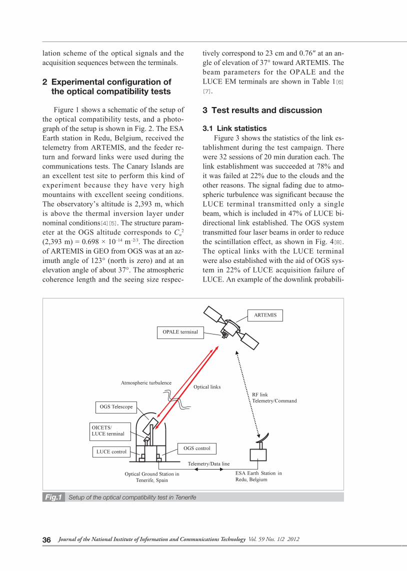
2 Experimental confi guration of the optical compatibility tests
Figure 1 shows a schematic of the setup of the optical compatibility tests, and a photo-graph of the setup is shown in Fig. 2. The ESA Earth station in Redu, Belgium, received the telemetry from ARTEMIS, and the feeder re-turn and forward links were used during the communications tests. The Canary Islands are an excellent test site to perform this kind of experiment because they have very high mountains with excellent seeing conditions. The observatory’s altitude is 2,393 m, which is above the thermal inversion layer under nominal conditions[4][5]. The structure param-eter at the OGS altitude corresponds to Cn
2
(2,393 m) = 0.698 × 10⁻¹⁴ m–2/3. The direction of ARTEMIS in GEO from OGS was at an az-imuth angle of 123° (north is zero) and at an elevation angle of about 37°. The atmospheric coherence length and the seeing size respec-
tively correspond to 23 cm and 0.76″ at an an-gle of elevation of 37° toward ARTEMIS. The beam parameters for the OPALE and the LUCE EM terminals are shown in Table 1[6][7].
3 Test results and discussion
3.1 Link statistics
Figure 3 shows the statistics of the link es-tablishment during the test campaign. There were 32 sessions of 20 min duration each. The link establishment was succeeded at 78% and it was failed at 22% due to the clouds and the other reasons. The signal fading due to atmo-spheric turbulence was significant because the LUCE terminal transmitted only a single beam, which is included in 47% of LUCE bi-directional link established. The OGS system transmitted four laser beams in order to reduce the scintillation effect, as shown in Fig. 4[8]. The optical links with the LUCE terminal were also established with the aid of OGS sys-tem in 22% of LUCE acquisition failure of LUCE. An example of the downlink probabili-
Setup of the optical compatibility test in TenerifeFig.1
36 Journal of the National Institute of Information and Communications Technology Vol. 59 Nos. 1/2 2012

ty density function is shown in Fig. 5. The role of OGS was to assist in the initial acquisition and to maintain the optical link between the LUCE terminal and the OPALE terminal dur-ing the experimental sessions. The initial ac-quisition used the LUCE terminal only, and succeeded autonomously without OGS sup-port when the LUCE terminal transmitted the CW laser beam. In all the communication ses-sions, once the ground-to-satellite optical link was established, it could be maintained with only the single beam transmitted from the LUCE terminal.
3.2 Downlink results
The OPALE terminal transmits a modulat-ed communications beam with a data rate of 2.048 Mbps. In spite of the variation in the op-tical downlink signal, the bit error count mea-sured by the LUCE terminal was zero during about 866 seconds of the session period, or er-
Specifi cations of the optical beamsTable 1
Terminal OPALE beam(s) LUCE EM beam
Wavelength Communication: 819 nm(Beacon: 801 nm)
Communication: 847 nm
Beam diameter (1/e2) 125 mm (at telescope aperture) 120 mm (at telescope aperture)
Transmitted power 10 mW (at telescope aperture) 40 mW (at telescope aperture)
Signal format 2 PPM NRZ
Data rate 2.048 Mbps 49.3724 Mbps
Polarization type LHCP LHCPLHCP: Left Handed Circular Polarization, 2 PPM: 2-Pulse Position Modulation, NRZ: Non Return to Zero.
Photograph of the optical compatibility test in Tenerife
Fig.2
Statistics of link establishment during the test campaignFig.3
37TOYOSHIMA Morio et al.

ror free, corresponding to a downlink bit error rate (BER) of better than 5.6 × 10⁻¹⁰. The re-sults show the communications performance of the forward link was perfect, with the static link margin of 7 dB. The communications function of the OPALE optical transmitter and the LUCE optical receiver was thus verified. The dominant power spectra of atmospheric turbulence reside below 10 Hz.
3.3 Uplink results
The LUCE terminal transmits a communi-cations signal modulated with PN code and a data rate of 49.3724 Mbps. The uplink error bits were counted every second by the OPALE terminal and the best uplink BER during 1 s
was 2.5 × 10⁻⁵. The average degradation in BER at around 10–4~10–3 is consistent with the static link margin of –1.47 dB[3]. For the on-orbit experiments, the communications perfor-mance of the return link was 6.45 dB better than the link budget analysis because there was no atmospheric turbulence and no atmo-spheric transmission loss in orbit. The uplink frequency components of atmospheric turbu-lence, mainly due to beam wander, reside be-low 30 Hz.
The far-field patterns of the transmitted la-ser beams from the LUCE terminal were mea-sured through the ground-to-satellite optical
Photograph of the uplink and downlink laser beams
Fig.4
Uplink probability density functions of LUCE with and without OGS assistance
Fig.5
Far-field pattern of the LUCE transmitted laser beam with a CW mode in the units of nW/m2
Fig.6
Far-fi eld pattern of the LUCE transmitted laser beam with a PN mode in the units of nW/m2
Fig.7
38 Journal of the National Institute of Information and Communications Technology Vol. 59 Nos. 1/2 2012

links during the tests. The LUCE terminal makes a raster scan by deflecting the point-ahead angles with 7 × 7 grids. The step angle is about 3 μrad. Figures 6 and 7 show the far-field patterns of the LUCE laser beams with the CW and the pseudo-noise modulation modes, which are mapped in the point-ahead angles of PA X and PA Y directions, respec-tively. The tip-tilt tracking performance was perfect within 0.81 μrad (3σ) during this ex-periment. In order to evaluate the far-fi eld pat-tern under the atmospheric turbulence, the short-term beam width at the satellite was cal-culated as 8.5 μrad (FWHM) based on the Hufnagel-Valley model. One can compare the calculated beam width and the measured far-field patterns as shown in Figs. 6 and 7, the theoretical values are in agreement with the measured data[9][10].
4 Conclusion
The optical compatibility test between the laser communications terminal onboard the OICETS satellite and the counter terminal car-ried on the ARTEMIS satellite was conducted. The downlink’s bit error rate was on the order of 10–10, in spite of atmospheric turbulence. Signal fading induced by atmospheric turbu-lence increased the uplink bit error rate, be-cause the turbulent layer near the Earth’s sur-face affects the uplink signal more than the downlink signal. The uplink bit error rate
achieved was 2.5 × 10⁻⁵ at best. This fact showed that the end-to-end optical characteris-tics such as intensity, sensitivity, wavelength, polarization, and the modulation scheme of optical signals were confi rmed. And the com-patibility of acquisition, tracking, pointing, and acquisition sequences of the terminals were also confirmed. From these results, a more accurate dynamic link design of the opti-cal communications link can be performed, which would be useful for system designs for space laser communications.
At the tail of this paper, as the test results verified the in-orbit design and operation of the optical terminals and the optical compati-bility for the optical communication link be-tween JAXA’s laser communications terminal and ESA’s counter terminal was confirmed before the launch of the OICETS satellite, this test contributed to the re-activation of the launch of the OICETS satellite.
Acknowledgments
The authors would like to express their ap-preciation to all the team members at ESA and IAC for their constant support during the prep-aration and execution of the tests. The authors also thank the engineers at NEC Toshiba Space Systems, Ltd. (the prime contractor of the OICETS satellite system) for their support in the tests.
References 1 K. Nakagawa, T. Yamawaki, T. Jono, M. Toyoshima, and A. Yamamoto, “Completion of Optical Inter-Orbit
Communications Engineering Test Satellite (OICETS),” 53rd International Astronautical Congress, the Interna-
tional Astronautical Federation, IAC-02-M.2.02, Huston, 10th–19th Oct. 2002.
2 M. Toyoshima, S. Yamakawa, T. Yamawaki, K. Arai, M. Reyes, A. Alonso, Z. Sodnik, and B. Demelenne,
“Ground-to-satellite optical link tests between Japanese laser communications terminal and European geo-
stationary satellite ARTEMIS,” in Free-Space Laser Communication Technologies XVI, Proc. SPIE 5338A,
pp. 1–15, 2004.
3 M. Toyoshima, S. Yamakawa, T. Yamawaki, K. Arai, M. Reyes, A. Alonso, Z. Sodnik, and B. Demelenne,
“Long-term statistics of laser beam propagation in an optical ground-to-geostationary satellite communica-
tions link,” IEEE trans. on Antennas and Propagation, Vol. 53, No. 2, pp. 842–850, Feb. 2005.
39TOYOSHIMA Morio et al.

4 D. Rutz, R. Czichy, J. Bara, A. Comeron, A. Belmonte, P. Menendez-Valdes, F. Blanco, and C.Pedreira, “In-
ter-Mountain laser communication tests,” in Free-Space Laser Communication Technologies II, Proc. SPIE
1218, pp. 419–430, 1990.
5 M. Reyes, J. A. Rodriguez, T. Viera, H. Moreno, J. L. Rasilla, F. Gago, L. F. Rodriguez, P. Gomez, and E.
Ballesteros, “Design and Performance of the ESA Optical Ground Station,” in Free-Space Laser Communi-
cation Technologies XIV, Proc. SPIE 4635, pp. 248–261, 2002.
6 T. T. Nielsen, G. Oppenhaeuser, B. Laurent, and G. Planche, “In-orbit test results of the optical intersatellite
link, SILEX. A milestone in satellite communication,” 53rd International Astronautical Congress, the Interna-
tional Astronautical Federation, IAC-02-M.2.01, Huston, 10th–19th Oct. 2002.
7 K. Nakagawa and A. Yamamoto, “Engineering model test of LUCE (Laser Utilizing Communications Equip-
ment),” in Free-Space Laser communication Technologies VIII, Proc. SPIE 2699, pp. 114–120, 1996.
8 M. Reyes, S. Chueca, A. Alonso, T. Viera, and Z. Sodnik, “Analysis of the preliminary optical links between
ARTEMIS and the Optical Ground Station,” in Free-Space Laser Communication and Laser Imaging II, Proc.
SPIE 4821, pp. 33–43, 2003.
9 L. C. Andrews and R. L. Phillips, “Laser Beam Propagation through Random Media,” SPIE Optical Engineer-
ing Press, Bellingham, Wash., 1998.
10 R. L. Fante, “Electromagnetic beam propagation in turbulent media,” Proc. IEEE, Vol. 63, No. 12, 1975.
(Accepted March 14, 2012)
40 Journal of the National Institute of Information and Communications Technology Vol. 59 Nos. 1/2 2012

TOYOSHIMA Morio, Ph.D.
Director, Space Communication Systems Laboratory, Wireless Network Research Institute
Satellite Communications, Atmospheric Turbulence, Laser Communications, Quantum Cryptography
YAMAKAWA Shiro, Ph.D.
Senior Engineer, Space Applications Mission Directorate, Space Applications Program Systems Engineering Office, Satellite Systems Engineering Group, Japan Aerospace Exploration Agency (JAXA)
Satellite System, Satellite Communications, Space Optical Communication
YAMAWAKI Toshihiko
Senior Engineer Technologist, Spacecraft Structures and Mechanisms Group, Aerospace Research and Development Directorate, Japan Aerospace Exploration Agency
Spacecraft Structure, Structure Dynamics, Pointing Error Caused by Micro-Vibration
ARAI Katsuyoshi
Director, Ground Facilities Department, Japan Aerospace Exploration Agency
Spacecraft Development Project (BSE, BS-2, MDS-1, OICETS), JEM Development Project
Marcos Reyes
Head of Projects Department-Technology Division, Instituto de Astrofisica de Canarias
Development of Astronomical Instrumentation, Visible and Infrared Instrumentation, Detectors, Telescopes, Adaptive Optics, Free Space Laser Communications
Angel Alonso, Ph.D.
Project Manager, Instituto de Astrofisica de Canarias, Tenerife Spain/ Associate Professor, Department of Basic Physics (University of La Laguna), Tenerife Spain
Laser Guide Stars, Beam Propagation in Atmosphere Turbulence, Stellar Structure, Astronomical Instrumentation
Zoran Sodnik, Ph.D.
Senior Optical Engineer, European Space Agency
ESA Optical Ground Station Manager,
Optical Communication, Optical Metrology and Interferometry
Benoit Demelenne
Engineer, Head of Redu Spacecraft Operations Unit, European Space Agency
41TOYOSHIMA Morio et al.