2k 8k l w sound analyzer tes-1358 db fast l 75.2 db ... · abrasives or solvents on this...
TRANSCRIPT
Sound Analyzer Real Time 1/1 & 1/3 Octave band Analysis
TES-1358
INSTRUCTION MANUAL
[ 1 / 3 OCT ] 01 / 07 / 27
14:26:39
100
WAL
Hz 12530
50
31.5 500
70
90
dB
FAST75.2 dB
8k2k L W
80
60
40
TES ELECTRICAL ELECTRONIC CORP.
CONTENTS Title Page
I. SAFETY INFORMATION..................................................... 1
II. GENERAL & FEATURES .................................................... 2
III. SPECIFICATIONS ............................................................... 2
IV. CONTROLS AND FUNCTIONS .......................................... 5
4-1 Parts description ............................................................................ 5
4-2 Operation keys ............................................................................... 7
4-3 Measurement screen ................................................................... 10
V. CALIBRATION PROCEDURES ........................................ 11
VI. MEASUREMENT PREPARATION .................................... 12
VII. SETTING THE DATE AND TIME ...................................... 12
VIII. SOUND PRESSURE LEVEL MEASUREMENT ................ 13
8-1 Technical notes ............................................................................ 13
8-2 Instantaneous sound pressure level measurement (LA, LC, LP) . 14
8-3 Leq and LE measurement ............................................................. 16
IX. MEMORY FUNCTION ....................................................... 18
9-1 Manual storing data in memory (1024 data sets) ....................... 18
9-2 Reading from memory ................................................................. 20
9-3 Auto storing data in memory ........................................................ 21
9-4 Erase memory data ..................................................................... 23
X. RS-232 INTERFACE, SOFTWARE INSTALLATION and OPERATION...................................................................... 23
1
I. SAFETY INFORMATION
Read the following safety information carefully before attempting to operate or service the meter.
Use the meter only as specified in this manual; otherwise, the protection provided by the meter may be impaired.
Environment conditions
Altitude up to 2000 meters
Relative humidity 90% max.
Operation Ambient 0 ~40℃
Maintenance & Clearing
Repairs or servicing not covered in this manual should only be performed by qualified personnel.
Periodically wipe the case with a dry cloth. Do not use abrasives or solvents on this instrument.
Safety symbols
Comply with EMC
2
II. GENERAL & FEATURES
The sound analyzer meter allows digital 1/1-octave and 1/3-octave analysis in real time.
Five measured parameters SPL (Sound Pressure Level), Leq (Equivalent Continuous Sound Pressure Level), LE (Sound Exposure Level), Lmax (Maximum Sound Pressure Level), Lmin (Minimum Sound Pressure Level)
RS-232 interface with PC.
Data Logger function.
Real time clock with calendar.
Both AC and DC signals output is available for level recorder, graphic recorder.
Auto-Ranging for SPL function.
III. SPECIFICATIONS
Standard applied : IEC 60651 type2, 60804 type 2, ANSI S1.4 type2, IEC 1260 (1995).
Display : Backlit LCD, 160×160 dots. Sound level meter mode
Numeric display : 4 digits, update rate 0.5S, resolution 0.1 dB. Bar graph display :100dB range, update rate 0.125S, resolution 1dB.
Frequency analysis mode Numeric display : 4 digits, update rate 0.5S, resolution 0.1dB. Bar graph display : 70dB range, update rate 0.125S, resolution 1 dB.
3
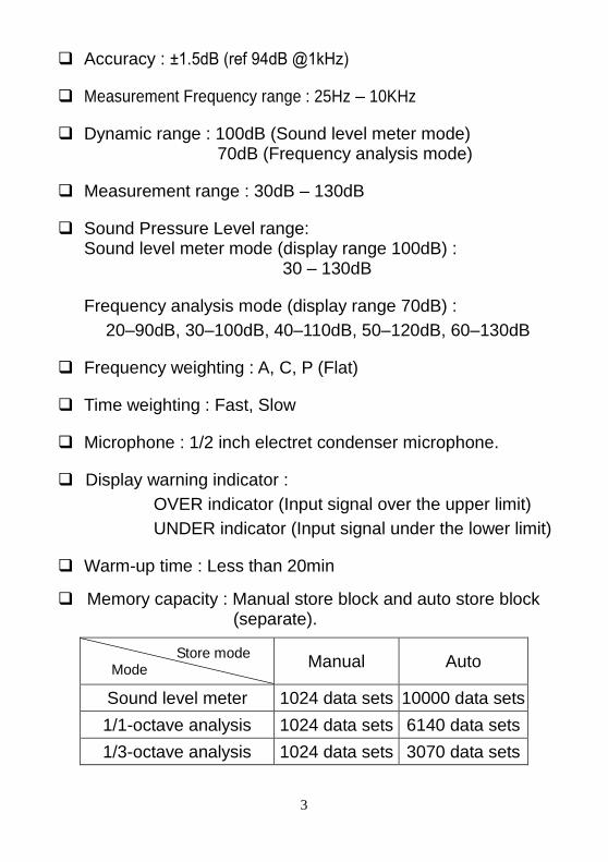
Accuracy : ±1.5dB (ref 94dB @1kHz)
Measurement Frequency range : 25Hz – 10KHz
Dynamic range : 100dB (Sound level meter mode) 70dB (Frequency analysis mode)
Measurement range : 30dB – 130dB
Sound Pressure Level range: Sound level meter mode (display range 100dB) :
30 – 130dB
Frequency analysis mode (display range 70dB) :
20–90dB, 30–100dB, 40–110dB, 50–120dB, 60–130dB
Frequency weighting : A, C, P (Flat)
Time weighting : Fast, Slow
Microphone : 1/2 inch electret condenser microphone.
Display warning indicator :
OVER indicator (Input signal over the upper limit)
UNDER indicator (Input signal under the lower limit)
Warm-up time : Less than 20min
Memory capacity : Manual store block and auto store block (separate).
Store mode Mode
Manual Auto
Sound level meter 1024 data sets 10000 data sets
1/1-octave analysis 1024 data sets 6140 data sets
1/3-octave analysis 1024 data sets 3070 data sets
4
AC output : 2 Vrms at FS (full scale). output impedance approx. 600Ω.
DC output : 10mV/dB. output impedance approx. 100Ω.
Power : 4 pcs of C size 1.5V (LR14) alkaline batteries.
External DC power supply : 6 Vdc, 1A.
Battery life : Approx. 2hours
Operating Temperature/Humidity : 0℃ to +40℃,10 to 90%RH.
Storage Temperature/Humidity : -10℃ to +60℃,10 to 75%RH.
(battery removal)
Dimensions & Weight : 34.5(H) × 10(W) × 6(D) cm Approx.950g (including batteries).
Accessories : Instruction manual, Alkaline battery × 4, Hard carry case, CD-ROM, RS-232 cable, ( 9 pin to 25 pin gender changer), Adjustment screw
driver, Windscreen, 3.5 plug, AC adaptor.
Optional accessories : Microphone extension cable (5m or 10m), Sound level calibrator, Tripod.

5
IV. CONTROLS AND FUNCTIONS
4-1 Parts description
FAST L
2k
[ 1 / 3 OCT ] 01 / 06 / 19 14:26:39
20
40
31.5Hz 500125
60
80
dB
100A W
W8k L
65.2 dB
IEC 1260 CLASS2
OF
FO
N
PO
WE
RC
AL
IEC LR14 1.5V X 4
ACCURACY : ¡ Ó1.5dB
OF
FO
ND
CA
C
CO
NT
RA
ST
OU
TP
UT
DC
6VLI
GH
T
SOUND ANALYZER
IEC 651 IEC 804 TYPE 2
1/1 & 1/3 OCTAVE BAND
1. Windscreen If you operate at wind speed over 10m/sec. Please put windscreen in front of the microphone.
2. Microphone The microphone assembly can be removed from the sound level meter and connected via an optional extension cable, for measurements a distance.
6
3. Display The backlit liquid crystal display has a resolution of 160×160 dots.
4. Operation keys
5. Power switch This sliding switch serves to turn the unit on and off.
6. Calibration adjust knob Serves to carry out calibration, using the supplied adjustment screwdriver.
7. DC 6V jack The AC adaptor can be plug here for powering the unit from an AC outlet for long term measurements.
8. DC output jack A DC signal corresponding to the sound pressure level is available at this output.
9. AC output jack A AC signal corresponding to the sound pressure is available at this output.
10. LCD contrast adjust knob Serves to adjust the display contrast. Use the supplied adjustment screwdriver for the adjustment.
11. LCD backlight switch Serves to turn the display backlight on and off.
12. Hand strap The strap should be used to safely carry the unit during field work.
13. RS-232 interface connector Serves for input and output of control signals and measurement data. A computer can be connected here.
14. Battery compartment The unit uses four batteries.
15. Tripod mounting screw For long term measurements, the unit can be mounted on the tripod.
7
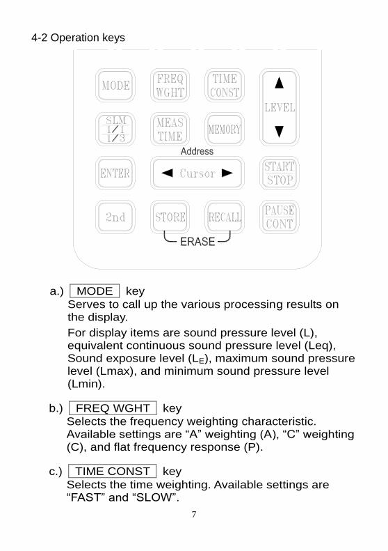
4-2 Operation keys
a.) MODE key
Serves to call up the various processing results on the display.
For display items are sound pressure level (L), equivalent continuous sound pressure level (Leq), Sound exposure level (LE), maximum sound pressure level (Lmax), and minimum sound pressure level (Lmin).
b.) FREQ WGHT key
Selects the frequency weighting characteristic. Available settings are “A” weighting (A), “C” weighting (C), and flat frequency response (P).
c.) TIME CONST key
Selects the time weighting. Available settings are “FAST” and “SLOW”.
8
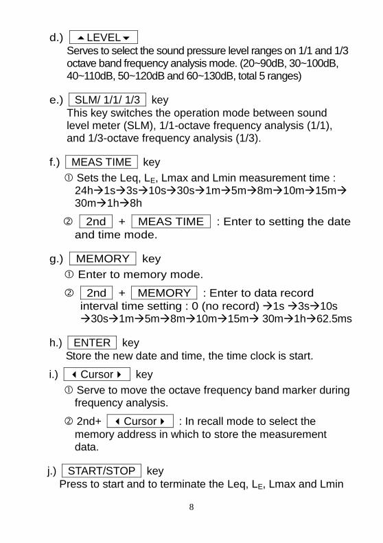
d.) LEVEL
Serves to select the sound pressure level ranges on 1/1 and 1/3 octave band frequency analysis mode. (20~90dB, 30~100dB, 40~110dB, 50~120dB and 60~130dB, total 5 ranges)
e.) SLM/ 1/1/ 1/3 key
This key switches the operation mode between sound level meter (SLM), 1/1-octave frequency analysis (1/1), and 1/3-octave frequency analysis (1/3).
f.) MEAS TIME key
Sets the Leq, LE, Lmax and Lmin measurement time : 24h1s3s10s30s1m5m8m10m15m 30m1h8h
2nd + MEAS TIME : Enter to setting the date
and time mode.
g.) MEMORY key
Enter to memory mode.
2nd + MEMORY : Enter to data record
interval time setting : 0 (no record) 1s 3s10s 30s1m5m8m10m15m 30m1h62.5ms
h.) ENTER key
Store the new date and time, the time clock is start.
i.) Cursor key
Serve to move the octave frequency band marker during frequency analysis.
2nd+ Cursor : In recall mode to select the
memory address in which to store the measurement data.
j.) START/STOP key
Press to start and to terminate the Leq, LE, Lmax and Lmin

9
sound pressure level measurement.
k.) PAUSE/CONT key
Server to the measurement temporarily pause ( display) or resume (display ).
l.) 2nd key
Press to shift key to second function.
m.) STORE key
In manual memory mode, store the measured data into the memory.
n.) RECALL key
In manual memory mode, recall the stored memory data.
o.) STORE + RECALL key (Erase memory data)
Turn off the meter, press and hold down STORE and RECALL two keys, then turn on the meter, until the LCD display “ALL memory are erased”.
10
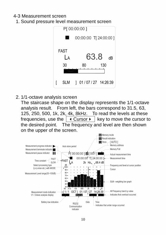
4-3 Measurement screen 1. Sound pressure level measurement screen
[ SLM ] 01 / 07 / 27 14:26:39
AL30 80
FAST
dB
130
2. 1/1-octave analysis screen
The staircase shape on the display represents the 1/1-octave analysis result. From left, the bars correspond to 31.5, 63, 125, 250, 500, 1k, 2k, 4k, 8kHz. To read the levels at these
frequencies, use the Cursor key to move the cursor to
the desired point. The frequency and level are then shown on the upper of the screen.
68.4 dB
[ 1 / 1 OCT ] 01 / 07 / 27 14:26:39
50
31.5 125Hz30
8k2k500
AL100dB
70
90
FAST2k Hz
L W
40
60
80
11
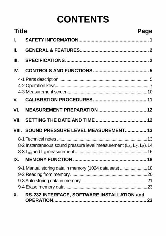
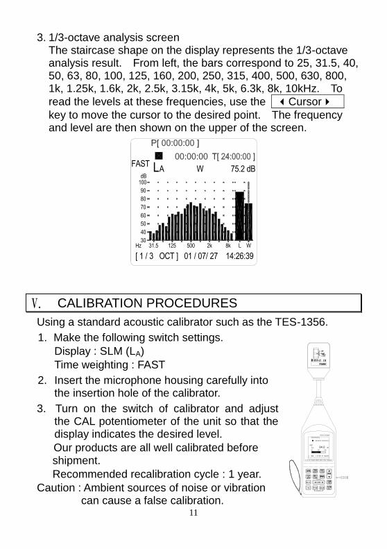
3. 1/3-octave analysis screen The staircase shape on the display represents the 1/3-octave analysis result. From left, the bars correspond to 25, 31.5, 40, 50, 63, 80, 100, 125, 160, 200, 250, 315, 400, 500, 630, 800, 1k, 1.25k, 1.6k, 2k, 2.5k, 3.15k, 4k, 5k, 6.3k, 8k, 10kHz. To
read the levels at these frequencies, use the Cursor
key to move the cursor to the desired point. The frequency and level are then shown on the upper of the screen.
[ 1 / 3 OCT ] 01 / 07/ 27 14:26:39
31.5Hz30
50
70
2k500125 8k L W
AFAST
90
dBL W 75.2 dB
100
60
80
40
V. CALIBRATION PROCEDURES
Using a standard acoustic calibrator such as the TES-1356.
1. Make the following switch settings.
Display : SLM (LA)
Time weighting : FAST
2. Insert the microphone housing carefully into the insertion hole of the calibrator.
3. Turn on the switch of calibrator and adjust the CAL potentiometer of the unit so that the display indicates the desired level.
Our products are all well calibrated before shipment.
Recommended recalibration cycle : 1 year.
Caution : Ambient sources of noise or vibration can cause a false calibration.
[ SLM ] 01 / 06 / 19 14:26:39
FAST
30
AL80
dB
130
12
VI. MEASUREMENT PREPARATION
1. Battery loading Remove the battery cover on the back and put in four 1.5V C size battery.
Note : Take care to observe battery polarity.
2. Battery replacement When the battery voltage drops below the operation voltage.
LBATT appears and flashes in the display. If it appears the
batteries should be replaced with new batteries.
3. AC adaptor connection When the AC adaptor is used, insert the plugs of the adaptor into the DC 6V jack on the side panel.
VII. SETTING THE DATE AND TIME
Date and time information is stored with each record you save. Therefore, it is important to make sure this information is correct. Set the date and time as described below :
1. Press 2nd key one time then press MEAS TIME key,
enter to setting the date and time mode. The display screen in second location will be flicker.
2. Press LEVEL key to set the numbers increase or
decrease.
3. Press Cursor key, move flicker number location to
year/month/day/hour/minute/second setting location.
4. Press LEVEL key to set the number.
5. When the setting is correct, press ENTER key to exit this
mode and the time clock is start.
Note : When no change the date and time or no press ENTER
key about one minute, will leave setting the date and time mode, the original setting date and time is no changed.
13
VIII. SOUND PRESSURE LEVEL MEASUREMENT
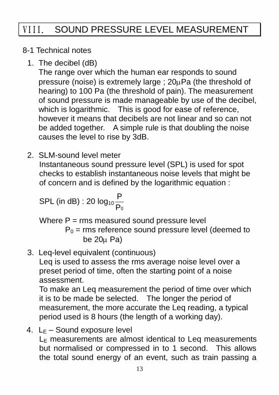
8-1 Technical notes
1. The decibel (dB) The range over which the human ear responds to sound
pressure (noise) is extremely large ; 20Pa (the threshold of hearing) to 100 Pa (the threshold of pain). The measurement of sound pressure is made manageable by use of the decibel, which is logarithmic. This is good for ease of reference, however it means that decibels are not linear and so can not be added together. A simple rule is that doubling the noise causes the level to rise by 3dB.
2. SLM-sound level meter Instantaneous sound pressure level (SPL) is used for spot checks to establish instantaneous noise levels that might be of concern and is defined by the logarithmic equation :
SPL (in dB) : 20 log100P
P
Where P = rms measured sound pressure level P0 = rms reference sound pressure level (deemed to
be 20 Pa)
3. Leq-level equivalent (continuous) Leq is used to assess the rms average noise level over a preset period of time, often the starting point of a noise assessment. To make an Leq measurement the period of time over which it is to be made be selected. The longer the period of measurement, the more accurate the Leq reading, a typical period used is 8 hours (the length of a working day).
4. LE – Sound exposure level LE measurements are almost identical to Leq measurements but normalised or compressed in to 1 second. This allows the total sound energy of an event, such as train passing a
14
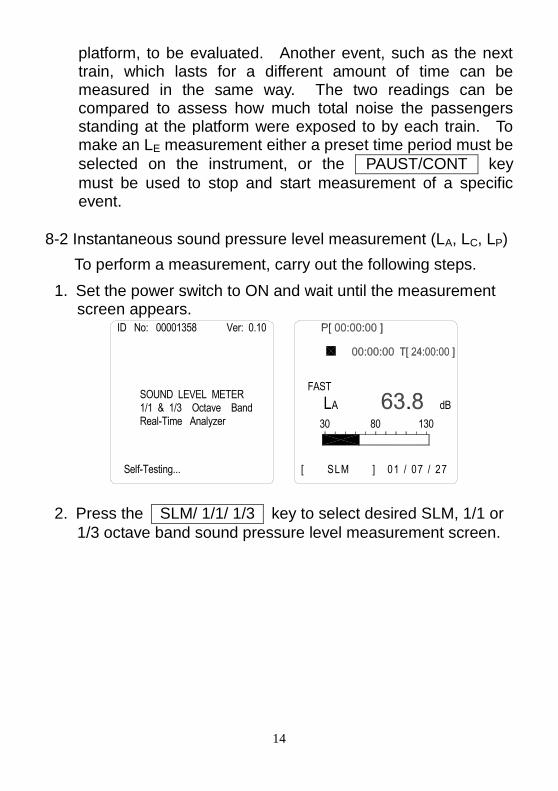
platform, to be evaluated. Another event, such as the next train, which lasts for a different amount of time can be measured in the same way. The two readings can be compared to assess how much total noise the passengers standing at the platform were exposed to by each train. To make an LE measurement either a preset time period must be
selected on the instrument, or the PAUST/CONT key
must be used to stop and start measurement of a specific event.
8-2 Instantaneous sound pressure level measurement (LA, LC, LP)
To perform a measurement, carry out the following steps.
1. Set the power switch to ON and wait until the measurement screen appears.
ID No: 00001358 Ver: 0.10
SOUND LEVEL METER1/1 & 1/3 Octave Band Real-Time Analyzer
Self-Testing...
[ SLM ] 01 / 07 / 27 14:26:39
AL30 80
FAST
dB
130
2. Press the SLM/ 1/1/ 1/3 key to select desired SLM, 1/1 or
1/3 octave band sound pressure level measurement screen.
15
70
500
[ 1 / 1 OCT ] 01 / 07 / 27 14:26:39
125Hz 31.530
50
8k L W2k
AFAST L
90
dB75.2 dBW
40
60
100
80
[ 1 / 3 OCT ] 01 / 07/ 27 14:26:39
3 1 . 5Hz30
50
70
2k500125 8k L W
AFAST
90
dBL W 75.2 dB
100
60
80
40
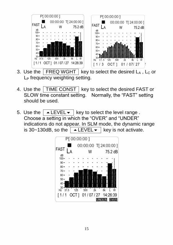
3. Use the FREQ WGHT key to select the desired LA , LC or
LP frequency weighting setting.
4. Use the TIME CONST key to select the desired FAST or
SLOW time constant setting. Normally, the “FAST” setting should be used.
5. Use the LEVEL key to select the level range .
Choose a setting in which the “OVER” and “UNDER” indications do not appear. In SLM mode, the dynamic range
is 30~130dB, so the LEVEL key is not activate.
[ 1 / 1 OCT ] 01 / 07 / 27 14:26:39
500
70
125Hz 31.5
60
40
30
50
AFAST L
100
80
90
dB
WL8k2k
75.2 dBW
16
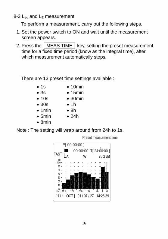
8-3 Leq and LE measurement
To perform a measurement, carry out the following steps.
1. Set the power switch to ON and wait until the measurement screen appears.
2. Press the MEAS TIME key, setting the preset measurement
time for a fixed time period (know as the integral time), after which measurement automatically stops.
There are 13 preset time settings available :
1s 10min
3s 15min
10s 30min
30s 1h
1min 8h
5min 24h
8min
Note : The setting will wrap around from 24h to 1s.
L
[ 1 / 1 OCT ] 01 / 07 / 27 14:26:39
FASTA W 75.2 dB
100
Hz 31.5 125 500 2k WL8k
dB
90
70
50
30
60
40
80
17
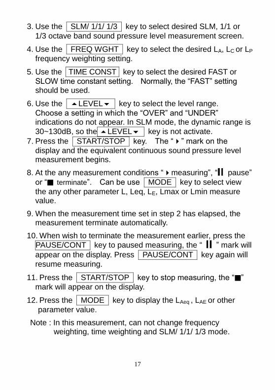
3. Use the SLM/ 1/1/ 1/3 key to select desired SLM, 1/1 or
1/3 octave band sound pressure level measurement screen.
4. Use the FREQ WGHT key to select the desired LA, LC or LP
frequency weighting setting.
5. Use the TIME CONST key to select the desired FAST or
SLOW time constant setting. Normally, the “FAST” setting should be used.
6. Use the LEVEL key to select the level range.
Choose a setting in which the “OVER” and “UNDER” indications do not appear. In SLM mode, the dynamic range is
30~130dB, so the LEVEL key is not activate.
7. Press the START/STOP key. The “” mark on the
display and the equivalent continuous sound pressure level measurement begins.
8. At the any measurement conditions “measuring”, “ pause”
or “■ terminate”. Can be use MODE key to select view
the any other parameter L, Leq, LE, Lmax or Lmin measure value.
9. When the measurement time set in step 2 has elapsed, the measurement terminate automatically.
10. When wish to terminate the measurement earlier, press the
PAUSE/CONT key to paused measuring, the “ ” mark will
appear on the display. Press PAUSE/CONT key again will
resume measuring.
11. Press the START/STOP key to stop measuring, the “■”
mark will appear on the display.
12. Press the MODE key to display the LAeq , LAE or other
parameter value.
Note : In this measurement, can not change frequency weighting, time weighting and SLM/ 1/1/ 1/3 mode.
18
IX. MEMORY FUNCTION
The sound analyzer incorporates a memory that allows manual and automatic storing of measurement data. Stored measurement
results can be displayed by pressing the RECALL key.
MANU (manual store)
Measured instantaneous value data and processing results can be stored manually by the operator.
AUTO (automatic store)
Automatically store measuring data at the measurement time interval.
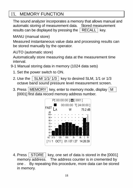
9-1 Manual storing data in memory (1024 data sets)
1. Set the power switch to ON.
2. Use the SLM/ 1/1/ 1/3 key to desired SLM, 1/1 or 1/3
octave band sound pressure level measurement screen.
3. Press MEMORY key, enter to memory mode, display M
[0001] first data record memory address number.
70
[ 1 / 1 OCT ] 01 / 07 / 27 14:26:39
31.5Hz
50
30
40
60
2k500125 8k L W
LFAST
dB
90
80
100
WA 75.2 dB
4. Press STORE key, one set of data is stored in the [0001]
memory address. The address counter is in cremented by one . By repeating this procedure, more data can be stored in memory.
19
5. Press MEMORY key again, exit the memory mode.
20
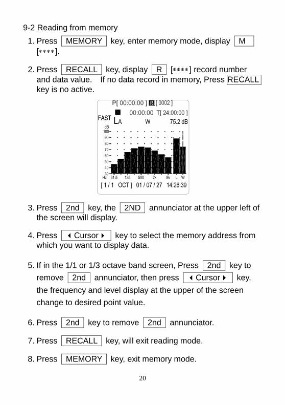
9-2 Reading from memory
1. Press MEMORY key, enter memory mode, display M
[].
2. Press RECALL key, display R [] record number
and data value. If no data record in memory, Press RECALL
key is no active.
70
[ 1 / 1 OCT ] 01 / 07 / 27 14:26:39
31.5Hz
50
30
40
60
2k500125 8k L W
LFAST
dB
90
80
100
WA 75.2 dB
3. Press 2nd key, the 2ND annunciator at the upper left of
the screen will display.
4. Press Cursor key to select the memory address from
which you want to display data.
5. If in the 1/1 or 1/3 octave band screen, Press 2nd key to
remove 2nd annunciator, then press Cursor key,
the frequency and level display at the upper of the screen
change to desired point value.
6. Press 2nd key to remove 2nd annunciator.
7. Press RECALL key, will exit reading mode.
8. Press MEMORY key, exit memory mode.
21
9-3 Auto storing data in memory
Before auto store data, first need setting record interval period. When in auto store data function, can not view other parameter measurement.
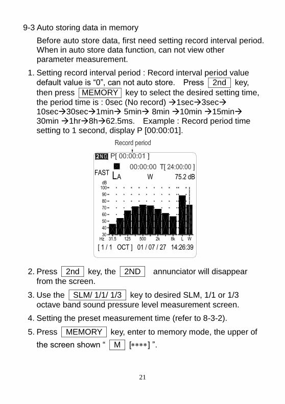
1. Setting record interval period : Record interval period value
default value is “0”, can not auto store. Press 2nd key,
then press MEMORY key to select the desired setting time,
the period time is : 0sec (No record) 1sec3sec 10sec30sec1min 5min 8min 10min 15min 30min 1hr8h62.5ms. Example : Record period time setting to 1 second, display P [00:00:01].
70
[ 1 / 1 OCT ] 01 / 07 / 27 14:26:39
31.5Hz
50
30
40
60
2k500125 8k L W
LFAST
dB
90
80
100
WA 75.2 dB
2. Press 2nd key, the 2ND annunciator will disappear
from the screen.
3. Use the SLM/ 1/1/ 1/3 key to desired SLM, 1/1 or 1/3
octave band sound pressure level measurement screen.
4. Setting the preset measurement time (refer to 8-3-2).
5. Press MEMORY key, enter to memory mode, the upper of
the screen shown “ M [] ”.
22
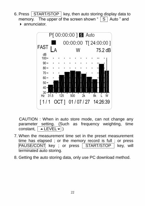
6. Press START/STOP key, then auto storing display data to
memory. The upper of the screen shown “ S Auto ” and
annunciator.
70
[ 1 / 1 OCT ] 01 / 07 / 27 14:26:39
31.5Hz
50
30
40
60
2k500125 8k L W
LFAST
dB
90
80
100
WA 75.2 dB
CAUTION : When in auto store mode, can not change any parameter setting. (Such as frequency weighting, time
constant, LEVEL )
7. When the measurement time set in the preset measurement time has elapsed ; or the memory record is full ; or press
PAUSE/CONT key ; or press START/STOP key, will
terminated auto storing.
8. Getting the auto storing data, only use PC download method.
23
9-4 Erase memory data
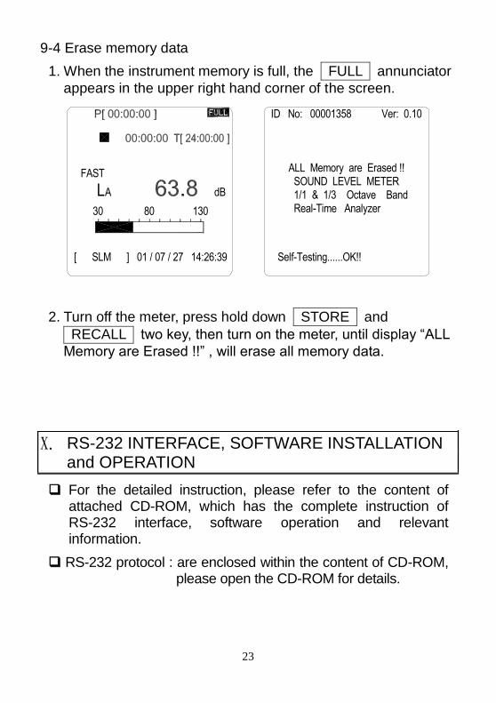
1. When the instrument memory is full, the FULL annunciator
appears in the upper right hand corner of the screen.
[ SLM ] 01 / 07 / 27 14:26:39
AL30 80
FAST
dB
130
ID No: 00001358 Ver: 0.10
SOUND LEVEL METER1/1 & 1/3 Octave Band Real-Time Analyzer
Self-Testing......OK!!
ALL Memory are Erased !!
2. Turn off the meter, press hold down STORE and
RECALL two key, then turn on the meter, until display “ALL
Memory are Erased !!” , will erase all memory data.
X. RS-232 INTERFACE, SOFTWARE INSTALLATION and OPERATION
For the detailed instruction, please refer to the content of attached CD-ROM, which has the complete instruction of RS-232 interface, software operation and relevant information.
RS-232 protocol : are enclosed within the content of CD-ROM, please open the CD-ROM for details.

TES ELECTRICAL ELECTRONIC CORP. 7F, No. 31, Lane 513, Rui Guang Road, Neihu Dist. Taipei, Taiwan, R. O. C. Tel : (02) 2799-3660 Fax : 886-2-2799-5099 E-Mail : [email protected] http://www.tes.com.tw
Jan-2007-4